JP2020007002A - Packing material for ornamental flower and packing material laminate - Google Patents
Packing material for ornamental flower and packing material laminate Download PDFInfo
- Publication number
- JP2020007002A JP2020007002A JP2018129739A JP2018129739A JP2020007002A JP 2020007002 A JP2020007002 A JP 2020007002A JP 2018129739 A JP2018129739 A JP 2018129739A JP 2018129739 A JP2018129739 A JP 2018129739A JP 2020007002 A JP2020007002 A JP 2020007002A
- Authority
- JP
- Japan
- Prior art keywords
- film
- packaging
- sleeve
- packaging material
- laminate
- Prior art date
- Legal status (The legal status is an assumption and is not a legal conclusion. Google has not performed a legal analysis and makes no representation as to the accuracy of the status listed.)
- Pending
Links
- 239000000463 material Substances 0.000 title claims abstract description 19
- 238000012856 packing Methods 0.000 title abstract description 7
- 238000004806 packaging method and process Methods 0.000 claims description 99
- 239000005022 packaging material Substances 0.000 claims description 52
- 238000010030 laminating Methods 0.000 claims description 2
- 238000000034 method Methods 0.000 description 9
- 238000005520 cutting process Methods 0.000 description 6
- 238000005304 joining Methods 0.000 description 6
- 238000004519 manufacturing process Methods 0.000 description 6
- -1 polyethylene Polymers 0.000 description 6
- 238000003825 pressing Methods 0.000 description 5
- 238000009864 tensile test Methods 0.000 description 4
- 239000004698 Polyethylene Substances 0.000 description 3
- 239000004743 Polypropylene Substances 0.000 description 3
- 229920000573 polyethylene Polymers 0.000 description 3
- 229920001155 polypropylene Polymers 0.000 description 3
- 229920005989 resin Polymers 0.000 description 3
- 239000011347 resin Substances 0.000 description 3
- 230000002093 peripheral effect Effects 0.000 description 2
- 229920005992 thermoplastic resin Polymers 0.000 description 2
- 238000010586 diagram Methods 0.000 description 1
- 230000012447 hatching Effects 0.000 description 1
- 238000010438 heat treatment Methods 0.000 description 1
Images







Landscapes
- Packging For Living Organisms, Food Or Medicinal Products That Are Sensitive To Environmental Conditiond (AREA)
- Bag Frames (AREA)
Abstract
Description
本発明は、花卉を包装する花卉用包装材、および花卉用包装材を積層した包装材積層体に関する。 The present invention relates to a packaging material for flowers for packaging flowers, and a packaging material laminate in which the packaging materials for flowers are laminated.
花束等の花卉を小売店で販売する際には、樹脂製や紙製のシートを用いて花卉を包装することが多い。しかしながら、シートを用いて花卉を包装することは、煩雑な作業であることから、花卉を包装する花卉用包装材として、テーパ状に加工された樹脂製の包装スリーブが提案されている(特許文献1参照)。この包装スリーブを用いることにより、花卉を挿入するだけで簡単に包装することができる。 When selling flowers such as bouquets at retail stores, flowers are often wrapped using resin or paper sheets. However, wrapping flowers using a sheet is a complicated operation, and thus a tape-shaped resin-made packaging sleeve has been proposed as a flower wrapping material for wrapping flowers (Patent Literature) 1). By using this packaging sleeve, packaging can be easily performed only by inserting flowers.
ところで、花卉用包装材である包装スリーブの材料として、ポリエチレンやポリプロピレン等の樹脂フィルムを用いることが多い。しかしながら、樹脂フィルムを用いた包装スリーブは強靱であることから、包装スリーブ内から花卉を取り出す際に包装スリーブを裂くことが困難であった。このため、簡単に開封することのできる花卉用包装材が求められている。 By the way, a resin film such as polyethylene or polypropylene is often used as a material of a packaging sleeve which is a packaging material for flowers. However, since the packaging sleeve using the resin film is tough, it has been difficult to tear the packaging sleeve when taking out flowers from inside the packaging sleeve. Therefore, there is a demand for a flower packaging material that can be easily opened.
本発明の目的は、簡単に開封することのできる花卉用包装材を提供することにある。 An object of the present invention is to provide a flower wrapping material that can be easily opened.
本発明の花卉用包装材は、花卉を包装する花卉用包装材であって、第1フィルムとこれに対向する第2フィルムとを備え、前記第1フィルムと前記第2フィルムとの側辺部が互いに接合される本体部と、前記第1フィルムと前記第2フィルムとの少なくとも何れか一方の上辺部に形成され、フィルム面に付けられた多数の切れ目からなる帯状の上辺脆弱部と、を有する。 The flower packaging material of the present invention is a flower packaging material for packing flowers, comprising a first film and a second film opposed thereto, and a side portion of the first film and the second film. Are bonded to each other, and a band-shaped upper-side fragile portion formed on the upper surface of at least one of the first film and the second film and having a plurality of cuts attached to the film surface. Have.
本発明の包装材積層体は、花卉を包装する花卉用包装材が積層される包装材積層体であって、複数の前記花卉用包装材が積層される包装材群と、前記花卉用包装材に切取線を介して連なる保持片を複数備え、複数の前記保持片が積層されて互いに接合される保持片群と、を有し、前記花卉用包装材は、前記保持片に前記切取線を介して連なる第1フィルムと、前記第1フィルムに対向して側辺部が互いに接合される第2フィルムと、を備え、前記第1フィルムと前記第2フィルムとの少なくとも何れか一方の上辺部に、フィルム面に付けられた多数の切れ目からなる帯状の上辺脆弱部が形成される。 The packaging material laminate of the present invention is a packaging material laminate in which a flower packaging material for packaging flowers is laminated, and a packaging material group in which a plurality of the flower packaging materials are laminated, and the flower packaging material. A plurality of holding pieces connected to each other via a cutting line, a plurality of holding pieces are stacked and joined to each other, and a holding piece group, and the flower packaging material is attached to the holding piece via the cutting line. A first film that is continuous, and a second film whose side portions are bonded to each other in opposition to the first film, and on at least one of the upper sides of the first film and the second film, A band-shaped upper-side fragile portion consisting of a large number of cuts formed on the film surface is formed.
本発明によれば、第1フィルムと第2フィルムとの少なくとも何れか一方の上辺部に、フィルム面に付けられた多数の切れ目からなる帯状の上辺脆弱部が形成される。これにより、花卉用包装材を簡単に開封することができる。 According to the present invention, a strip-shaped upper-side fragile portion consisting of a number of cuts formed on the film surface is formed on the upper side of at least one of the first film and the second film. Thereby, the flower packaging material can be easily opened.
以下、本発明の実施の形態を図面に基づいて詳細に説明する。 Hereinafter, embodiments of the present invention will be described in detail with reference to the drawings.
[包装スリーブ]
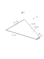
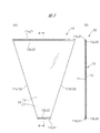
図1は本発明の一実施の形態である包装スリーブ(花卉用包装材)10を示す斜視図である。図2(A)は包装スリーブ10を示す正面図であり、図2(B)は図2(A)のa−a線に沿って包装スリーブ10を示す断面図である。また、図3は包装スリーブ10の一部を拡大して示す部分拡大図である。なお、図2および図3には、後述する上辺脆弱部21,22および下辺脆弱部31,32がハッチングで示されている。
[Packing sleeve]
FIG. 1 is a perspective view illustrating a packaging sleeve (flower packaging material) 10 according to an embodiment of the present invention. FIG. 2A is a front view showing the
図1および図2に示すように、包装スリーブ10の本体部13は、シート状の裏側フィルム(第1フィルム)11と、これに対向するシート状の表側フィルム(第2フィルム)12と、を有している。裏側フィルム11は、上辺部11aと、これに平行であって上辺部11aよりも短い下辺部11bと、互いに傾斜する左右の側辺部11c,11dと、を有している。同様に、表側フィルム12は、上辺部12aと、これに平行であって上辺部12aよりも短い下辺部12bと、互いに傾斜する左右の側辺部12c,12dと、を有している。また、表側フィルム12の上辺部12aは、裏側フィルム11の上辺部11aよりも下側に位置しており、表側フィルム12の下辺部12bは、裏側フィルム11の下辺部11bよりも上側に位置している。
As shown in FIGS. 1 and 2, the
裏側フィルム11の側辺部11cと表側フィルム12の側辺部12cとは互いに接合されており、裏側フィルム11の側辺部11dと表側フィルム12の側辺部12dとは互いに接合されている。裏側フィルム11および表側フィルム12の素材としては、ポリエチレンやポリプロピレン等の熱可塑性樹脂が用いられる。このため、側辺部11c,11d,12c,12dを加熱して圧着することにより、側辺部11c,11d,12c,12dは互いに溶けて接合される。
The
ヒートシール部分である側辺部11c,11d,12c,12dの接合強度としては、包装スリーブ10の実用性を確保する観点から、0.6kgf/15mm以上であることが望ましい。側辺部11c,11d,12c,12dの接合強度は、日本工業規格JIS Z 0238に準拠した方法で測定される。例えば、側辺部11c,12cの接合強度を測定する際には、包装スリーブ10から側辺部11c,12cに対して直角の方向に幅15mmの試験片が切り出される。そして、切り出し後に展開された試験片に対して、定速緊張形引張試験機であるショッパー試験機を用いた引張試験が施される。なお、引張試験の条件としては、引張速度が300mm/minであり、温度が23℃であり、湿度が50%である。このように、側辺部11c,12cの接合強度が「0.6kgf/15mm」以上であるということは、幅寸法が15mmの試験片を対象とした上記の引張試験において、側辺部11c,12cの破断荷重が0.6kgf以上であることを意味している。同様に、側辺部11d,12dの接合強度が「0.6kgf/15mm」以上であるということは、幅寸法が15mmの試験片を対象とした上記の引張試験において、側辺部11d,12dの破断荷重が0.6kgf以上であることを意味している。
The bonding strength of the
図3の拡大部分αに示すように、裏側フィルム11の上辺部11aには、帯状の上辺脆弱部21が形成される。この上辺脆弱部21のフィルム面には、多数の微細な切れ目21aが形成されている。つまり、裏側フィルム11の上辺部11aには、フィルム面に付けられた多数の切れ目21aからなる上辺脆弱部21が形成されている。同様に、表側フィルム12の上辺部12aには、帯状の上辺脆弱部22が形成される。この上辺脆弱部22のフィルム面には、多数の微細な切れ目22aが形成されている。つまり、表側フィルム12の上辺部12aには、フィルム面に付けられた多数の切れ目22aからなる上辺脆弱部22が形成されている。
As shown in the enlarged portion α in FIG. 3, a band-shaped upper-side
また、図3の拡大部分βに示すように、裏側フィルム11の下辺部11bには、帯状の下辺脆弱部31が形成される。この下辺脆弱部31のフィルム面には、多数の微細な切れ目31aが形成されている。つまり、裏側フィルム11の下辺部11bには、フィルム面に付けられた多数の切れ目31aからなる下辺脆弱部31が形成されている。同様に、表側フィルム12の下辺部12bには、帯状の下辺脆弱部32が形成される。この下辺脆弱部32のフィルム面には、多数の微細な切れ目32aが形成されている。つまり、表側フィルム12の下辺部12bには、フィルム面に付けられた多数の切れ目32aからなる下辺脆弱部32が形成されている。
Further, as shown in an enlarged portion β in FIG. 3, a band-shaped lower side
なお、切れ目21a,31aが付けられるフィルム面とは、裏側フィルム11の表面や裏面を意味し、切れ目22a,32aが付けられるフィルム面とは、表側フィルム12の表面や裏面を意味している。つまり、裏側フィルム11に切れ目21a,31aを付ける際には、裏側フィルム11の表面から切れ目21a,31aを付けても良く、裏側フィルム11の裏面から切れ目21a,31aを付けても良い。同様に、表側フィルム12に切れ目22a,32aを付ける際には、表側フィルム12の表面から切れ目22a,32aを付けても良く、表側フィルム12の裏面から切れ目22a,32aを付けても良い。また、裏側フィルム11に付けられる切れ目21a,31aとしては、裏側フィルム11を貫通しても良く、裏側フィルム11を貫通していなくても良い。また、表側フィルム12に付けられる切れ目22a,32aとしては、表側フィルム12を貫通しても良く、表側フィルム12を貫通していなくても良い。また、一例として図示した切れ目21a,22a,31a,32aは、0.5mmの長さ寸法を備えた直線状の切れ目であるが、これに限られることはなく、他の長さ寸法や形状を備えた切れ目を採用しても良い。
In addition, the film surface on which the
[スリーブ積層体]
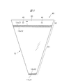
図4は本発明の一実施の形態であるスリーブ積層体(包装材積層体)40を示す斜視図である。図5はスリーブ積層体40を示す正面図であり、図6はスリーブ積層体40の一部を拡大して示す部分拡大図である。なお、図5および図6には、上辺脆弱部21,22および下辺脆弱部31,32がハッチングで示されている。また、図4〜図6において、図1〜図3に示した部位と同じ部位については、同一の符号を付してその説明を省略する。
[Sleeve laminate]
FIG. 4 is a perspective view showing a sleeve laminate (packaging material laminate) 40 according to one embodiment of the present invention. FIG. 5 is a front view showing the
図4および図5に示すように、スリーブ積層体40は、積層された複数の包装スリーブ10からなるスリーブ群(包装材群)41と、このスリーブ群41を束ねて保持する保持片群42と、を有している。スリーブ積層体40の保持片群42は、複数枚の保持片43によって構成されており、それぞれの保持片43は、包装スリーブ10の裏側フィルム11にミシン目(切取線)44を介して連なっている。保持片43の素材としては、裏側フィルム11と同様に、ポリエチレンやポリプロピレン等の熱可塑性樹脂が用いられる。図示する例では、保持片群42に対して加熱された刃物を押し付けることにより、保持片群42には内周面が溶けて接合した貫通孔45が形成される。これにより、複数枚の保持片43を一体に接合することができるため、一体となった保持片群42によって複数枚の包装スリーブ10を束ねることができる。
As shown in FIGS. 4 and 5, the
また、図6の拡大部分αに示すように、裏側フィルム11の上辺部11aには、ミシン目44を介して保持片43が連なっている。そして、裏側フィルム11と保持片43との双方には、境界部分のミシン目44を覆うように、多数の微細な切れ目21aからなる帯状の上辺脆弱部21が形成されている。つまり、ミシン目44に重なって裏側フィルム11と保持片43との双方には、フィルム面に付けられた多数の切れ目21aからなる上辺脆弱部21が形成されている。
As shown in the enlarged portion α in FIG. 6, a holding
このようなスリーブ積層体40を用いて花束を包装する際には、スリーブ積層体40を図示しないスタンドに吊り下げた状態のもとで、最前面に位置する包装スリーブ10のフィルム11,12間に花束が挿入される。そして、花束が挿入された包装スリーブ10は、ミシン目44に沿ってスリーブ積層体40から破り取られる。ここで、前述したように、裏側フィルム11と保持片43との双方には、ミシン目44に重なって帯状の上辺脆弱部21が形成されている。これにより、図3の拡大部分αに示すように、ミシン目44に沿って破り取られた包装スリーブ10には、上辺部11aの上端まで広がる上辺脆弱部21が形成されている。
When wrapping a bouquet using such a
[包装スリーブの製造過程]
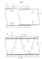
包装スリーブ10の製造過程について説明する。図7(A)、図7(B)および図8は、包装スリーブ10の製造過程の一例を示す説明図である。
[Production process of packaging sleeve]
The manufacturing process of the
図7(A)に示すように、包装スリーブ10を製造する際には、裏側フィルム11の材料である帯状フィルム51と、表側フィルム12の材料である帯状フィルム52と、が準備される。帯状フィルム51の幅寸法は、帯状フィルム52の幅寸法よりも広く形成されている。裏側フィルム11の材料である帯状フィルム51の幅方向の両端部には、図示しない回転カッターを押し付けることにより、点線状の切れ目であるミシン目44が形成される。また、帯状フィルム51の幅方向の両端部には、図示しない回転カッターを押し付けることにより、多数の微細な切れ目からなる帯状の脆弱帯部61が、ミシン目44に重なる位置に形成される。また、表側フィルム12の材料である帯状フィルム52の幅方向の両端部には、図示しない回転カッターを押し付けることにより、多数の微細な切れ目からなる帯状の脆弱帯部62が形成される。
As shown in FIG. 7A, when manufacturing the
続いて、図7(B)に示すように、帯状フィルム51と帯状フィルム52とを互いに重ねた状態のもとで、切断線Xに沿って図示しない溶断カッターを押し付けることにより、帯状フィルム51,52から台形状の包装スリーブ10が切り出される。溶断カッターは加熱されており、帯状フィルム51,52から包装スリーブ10を切り出す際に、図8に示すように、包装スリーブ10の側辺部11c,11d,12c,12dが溶けて接合される。なお、帯状フィルム51,52から歩留まり良く包装スリーブ10を切り出すため、隣り合う包装スリーブ10の上下を反転させながら包装スリーブ10が切り出される。
Subsequently, as shown in FIG. 7B, in a state where the band-shaped
そして、図8に示すように、切り出された包装スリーブ10の下辺部11b,12bから、余ったフィルム片70がミシン目44に沿って除去される。その後、保持片43を備えた包装スリーブ10を積層した後に、前述したように、保持片群42に対して加熱された刃物を押し付けることにより、保持片群42には内周面が溶けて接合された貫通孔45が形成される。これにより、複数枚の保持片43が一体に接合され、複数枚の包装スリーブ10を束ねたスリーブ積層体40が完成する。
Then, as shown in FIG. 8, the
[包装スリーブの開封手順]
続いて、包装スリーブ10の開封手順について説明する。図9〜図11は、包装スリーブ10の開封手順の一例を示す図である。
[Opening procedure of packaging sleeve]
Next, a procedure for opening the
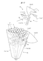
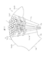
図9に示すように、包装スリーブ10には花束(花卉)Fが挿入されている。この包装スリーブ10から花束Fを取り出す際には、矢印Xaで示すように、包装スリーブ10が上辺部12aから側辺部11d,12dに向けて手で引き裂かれる。ここで、包装スリーブ10の上辺部12aには、多数の切れ目22aからなる上辺脆弱部22が形成されるため、簡単に包装スリーブ10を手で裂くことができる。続いて、図10に示すように、包装スリーブ10が側辺部11d,12dまで裂かれると、矢印Xbで示すように、包装スリーブ10が側辺部11d,12dやその近傍に沿って引き裂かれる。そして、図11に示すように、包装スリーブ10が下辺部11b,12bまで裂かれると、花束Fを露出させることができるため、花束Fを傷つけることなく簡単に取り出すことができる。
As shown in FIG. 9, a bouquet (flowers) F is inserted into the
このように、包装スリーブ10に上辺脆弱部22を形成することにより、包装スリーブ10の側辺部11d,12dまで容易に裂くことができるため、側辺部11d,12dの接合強度が高い場合であっても、包装スリーブ10を側辺部11d,12dやその近傍に沿って引き裂くことができる。これにより、包装スリーブ10の実用性を確保する観点から、側辺部11d,12d(11c,12c)の接合強度が0.6kgf/15mm以上に設定された場合であっても、簡単に包装スリーブ10を開封して花束Fを取り出すことができる。なお、側辺部11d,12d(11c,12c)の接合強度が0.6kgf/15mm未満に設定されていた場合であっても、包装スリーブ10に上辺脆弱部22等を形成することにより、包装スリーブ10の開封作業が極めて容易になることは言うまでもない。
As described above, by forming the upper side
また、図9〜図11に示した例では、包装スリーブ10を開封する際に、表側フィルム12を上辺脆弱部22から側辺部11d,12dに向けて裂いているが、これに限られることはない。ここで、図12は、包装スリーブ10の開封手順の他の例を示す図である。図12に示すように、包装スリーブ10から花束Fを取り出す際には、矢印Xaで示すように、包装スリーブ10が上辺部12aから下辺部12bに向けて手で引き裂かれる。ここで、包装スリーブ10の上辺部12aには、多数の切れ目22aからなる上辺脆弱部22が形成されるため、簡単に包装スリーブ10を手で裂くことができる。そして、包装スリーブ10が下辺部12bまで裂かれると、花束Fを露出させることができるため、花束Fを傷つけることなく簡単に取り出すことができる。
Further, in the example shown in FIGS. 9 to 11, when opening the
なお、前述の図9〜図11に示した例では、包装スリーブ10を開封する際に、包装スリーブ10を上辺部12aから側辺部11d,12dに向けて裂いているが、これに限られることはない。例えば、包装スリーブ10を開封する際に、包装スリーブ10を上辺部11aから裂き始めても良く、包装スリーブ10を下辺部11b,12bから裂き始めても良い。また、包装スリーブ10を開封する際に、包装スリーブ10を、上辺部11a,12aや下辺部11b,12bから、他方の側辺部11c,12cに向けて裂いても良い。同様に、図12に示した例では、包装スリーブ10を開封する際に、包装スリーブ10を上辺部12aから下辺部12bに向けて裂いているが、これに限られることはない。例えば、包装スリーブ10を開封する際に、包装スリーブ10を上辺部11aから裂き始めても良く、包装スリーブ10を下辺部11b,12bから裂き始めても良い。
In the examples shown in FIGS. 9 to 11 described above, when the
[他の実施形態]
図13(A)は本発明の他の実施形態であるスリーブ積層体(包装材積層体)70を示す部分拡大図であり、図13(B)は本発明の他の実施形態である包装スリーブ(花卉用包装材)71を示す部分拡大図である。また、図14(A)は本発明の他の実施形態であるスリーブ積層体(包装材積層体)80を示す部分拡大図であり、図14(B)は本発明の他の実施形態である包装スリーブ(花卉用包装材)81を示す部分拡大図である。なお、図13および図14において、図3および図6に示した部位と同様の部位については、同一の符号を付してその説明を省略する。
[Other embodiments]
FIG. 13A is a partially enlarged view showing a sleeve laminate (packaging material laminate) 70 according to another embodiment of the present invention, and FIG. 13B is a packaging sleeve according to another embodiment of the present invention. It is the elements on larger scale which show (wrapping material for flowers) 71. FIG. 14A is a partially enlarged view showing a sleeve laminate (packaging material laminate) 80 according to another embodiment of the present invention, and FIG. 14B is another embodiment of the present invention. It is a partial enlarged view which shows the packaging sleeve (flower packaging material) 81. In FIGS. 13 and 14, the same parts as those shown in FIGS. 3 and 6 are denoted by the same reference numerals and the description thereof will be omitted.
図3および図6に示した例では、裏側フィルム11と表側フィルム12との双方に、上辺脆弱部21,22を形成しているが、これに限られることはない。図13(A)および(B)に示すように、表側フィルム12に上辺脆弱部22を形成する一方、裏側フィルム11から上辺脆弱部21を省略しても良い。また、図14(A)および(B)に示すように、裏側フィルム11に上辺脆弱部21を形成する一方、表側フィルム12から上辺脆弱部22を省略しても良い。
In the example shown in FIGS. 3 and 6, the upper side
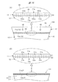
図15(A)は本発明の他の実施形態であるスリーブ積層体(包装材積層体)90を示す部分拡大図であり、図15(B)は本発明の他の実施形態である包装スリーブ(花卉用包装材)91を示す部分拡大図である。また、図16(A)は本発明の他の実施形態であるスリーブ積層体(包装材積層体)100を示す部分拡大図であり、図16(B)は本発明の他の実施形態である包装スリーブ(花卉用包装材)101を示す部分拡大図である。なお、図15および図16において、図3および図6に示した部位と同様の部位については、同一の符号を付してその説明を省略する。 FIG. 15A is a partially enlarged view showing a sleeve laminate (packaging material laminate) 90 according to another embodiment of the present invention, and FIG. 15B is a packaging sleeve according to another embodiment of the present invention. It is the elements on larger scale which show (the packaging material for flowers) 91. FIG. 16A is a partially enlarged view showing a sleeve laminate (packaging material laminate) 100 according to another embodiment of the present invention, and FIG. 16B is another embodiment of the present invention. FIG. 2 is a partially enlarged view showing a packaging sleeve (flower packaging material) 101. In FIGS. 15 and 16, the same parts as those shown in FIGS. 3 and 6 are denoted by the same reference numerals, and the description thereof will be omitted.
図7に示した例では、裏側フィルム11の材料である帯状フィルム51に、多数の微細な切れ目からなる帯状の脆弱帯部61が形成され、表側フィルム12の材料である帯状フィルム52に、多数の微細な切れ目からなる帯状の脆弱帯部62が形成される。これにより、図6に示すように、裏側フィルム11および表側フィルム12に対して、別個に上辺脆弱部21,22を形成しているが、これに限られることはない。
In the example shown in FIG. 7, a band-shaped
図15(A)に示すように、表側フィルム12の上辺部12a、裏側フィルム11の上辺部11a、および保持片43に跨がるように、多数の微細な切れ目92aからなる帯状の上辺脆弱部92を形成しても良い。この場合には、図15(B)に示すように、1本の上辺脆弱部92が、裏側フィルム11の上辺脆弱部21として機能し、表側フィルム12の上辺脆弱部22として機能する。また、図16(A)に示すように、表側フィルム12の上辺部12a、および裏側フィルム11の上辺部11aに跨がるように、多数の微細な切れ目102aからなる帯状の上辺脆弱部102を形成しても良い。この場合には、図16(B)に示すように、1本の上辺脆弱部102が、裏側フィルム11の上辺脆弱部21として機能し、表側フィルム12の上辺脆弱部22として機能する。
As shown in FIG. 15A, a strip-shaped upper-side weak portion composed of a number of
本発明は前記実施の形態に限定されるものではなく、その要旨を逸脱しない範囲で種々変更可能であることはいうまでもない。前述の説明では、包装スリーブ10,71,81,91,101によって包装される花卉として花束を挙げているが、包装される花卉としては花物に限られることはなく葉物や実物であっても良い。また、前述の説明では、包装スリーブ10,71,81,91,101を台形状に形成しているが、これに限られることはなく、包装スリーブ10,71,81,91,101を台形以外に形成しても良い。例えば、側辺部11c,11d,12c,12dを曲線状に形成しても良く、上辺部11a,12aや下辺部11b,12bを曲線状に形成しても良い。また、前述の説明では、包装スリーブ10,71,81,91,101の上辺部11a,12aと下辺部11b,12bとの双方を開いているが、これに限られることはなく、包装スリーブ10,71,81,91,101の下辺部11b,12bを互いに接合して閉じても良い。
The present invention is not limited to the above-described embodiment, and it goes without saying that various changes can be made without departing from the scope of the invention. In the above description, a bouquet is given as a flower to be wrapped by the
図示する例では、上辺部11a,12aの縁に達するまで、上辺脆弱部21,22を広げて形成しているが、これに限られることはなく、上辺部11a,12aの縁から離して上辺脆弱部21,22を形成しても良い。同様に、図示する例では、下辺部11b,12bの縁に達するまで、下辺脆弱部31,32を広げて形成しているが、これに限られることはなく、下辺部11b,12bの縁から離して下辺脆弱部31,32を形成しても良い。また、前述の説明では、裏側フィルム11と表側フィルム12との双方に、下辺脆弱部31,32を形成しているが、これに限られることはない。例えば、裏側フィルム11と表側フィルム12との双方から下辺脆弱部31,32を省略しても良い。また、裏側フィルム11だけに下辺脆弱部31を形成しても良く、表側フィルム12だけに下辺脆弱部32を形成しても良い。
In the illustrated example, the upper side
10 包装スリーブ(花卉用包装材)
11 裏側フィルム(第1フィルム)
11a 上辺部
11b 下辺部
11c,11d 側辺部
12 表側フィルム(第2フィルム)
12a 上辺部
12b 下辺部
12c,12d 側辺部
13 本体部
21 上辺脆弱部
21a 切れ目
22 上辺脆弱部
22a 切れ目
31 下辺脆弱部
31a 切れ目
32 下辺脆弱部
32a 切れ目
40 スリーブ積層体(包装材積層体)
41 スリーブ群(包装材群)
42 保持片群
43 保持片
44 ミシン目(切取線)
70 スリーブ積層体(包装材積層体)
71 包装スリーブ(花卉用包装材)
80 スリーブ積層体(包装材積層体)
81 包装スリーブ(花卉用包装材)
90 スリーブ積層体(包装材積層体)
91 包装スリーブ(花卉用包装材)
92 上辺脆弱部
100 スリーブ積層体(包装材積層体)
101 包装スリーブ(花卉用包装材)
102 上辺脆弱部
10. Packaging sleeve (flower packaging material)
11 Back film (first film)
41 Sleeve group (packing material group)
42 holding
70 Sleeve laminate (packaging material laminate)
71 Packaging sleeve (wrapping material for flowers)
80 Sleeve laminate (packaging material laminate)
81 Packaging sleeve (flower packaging material)
90 Sleeve laminate (packaging material laminate)
91 Packaging sleeve (wrapping material for flowers)
92 Upper
101 Packaging sleeve (wrapping material for flowers)
102 Upper fragile part
Claims (4)
第1フィルムとこれに対向する第2フィルムとを備え、前記第1フィルムと前記第2フィルムとの側辺部が互いに接合される本体部と、
前記第1フィルムと前記第2フィルムとの少なくとも何れか一方の上辺部に形成され、フィルム面に付けられた多数の切れ目からなる帯状の上辺脆弱部と、
を有する、花卉用包装材。 A flower wrapping material for wrapping flowers,
A main body portion including a first film and a second film facing the first film, wherein side portions of the first film and the second film are joined to each other;
A strip-shaped upper-side fragile portion formed on the upper side of at least one of the first film and the second film and formed of a number of cuts attached to the film surface;
A packaging material for flowers.
前記第1フィルムと前記第2フィルムとの少なくとも何れか一方の下辺部に形成され、フィルム面に付けられた多数の切れ目からなる帯状の下辺脆弱部、を有する、
花卉用包装材。 The packaging material for flowers according to claim 1,
A belt-shaped lower-side weak portion formed on a lower surface of at least one of the first film and the second film and having a number of cuts attached to the film surface,
Packaging material for flowers.
複数の前記花卉用包装材が積層される包装材群と、
前記花卉用包装材に切取線を介して連なる保持片を複数備え、複数の前記保持片が積層されて互いに接合される保持片群と、
を有し、
前記花卉用包装材は、前記保持片に前記切取線を介して連なる第1フィルムと、前記第1フィルムに対向して側辺部が互いに接合される第2フィルムと、を備え、
前記第1フィルムと前記第2フィルムとの少なくとも何れか一方の上辺部に、フィルム面に付けられた多数の切れ目からなる帯状の上辺脆弱部が形成される、
包装材積層体。 A packaging material laminate obtained by laminating floral packaging materials for packaging flowers,
A packaging material group in which a plurality of the floral packaging materials are stacked,
A plurality of holding pieces connected to the flower packaging material via a cut line, and a plurality of holding pieces stacked and joined to each other,
Has,
The flower packaging material includes: a first film connected to the holding piece via the cutout line; and a second film having sides joined to each other in opposition to the first film,
On the upper side of at least one of the first film and the second film, a band-shaped upper side fragile portion including a number of cuts attached to the film surface is formed.
Packaging laminate.
前記上辺脆弱部は、前記切取線に重なって前記第1フィルムと前記保持片との双方に形成される、
包装材積層体。 The packaging material laminate according to claim 3,
The upper brittle portion is formed on both the first film and the holding piece so as to overlap the cut line,
Packaging laminate.
Priority Applications (1)
| Application Number | Priority Date | Filing Date | Title |
|---|---|---|---|
| JP2018129739A JP2020007002A (en) | 2018-07-09 | 2018-07-09 | Packing material for ornamental flower and packing material laminate |
Applications Claiming Priority (1)
| Application Number | Priority Date | Filing Date | Title |
|---|---|---|---|
| JP2018129739A JP2020007002A (en) | 2018-07-09 | 2018-07-09 | Packing material for ornamental flower and packing material laminate |
Publications (1)
| Publication Number | Publication Date |
|---|---|
| JP2020007002A true JP2020007002A (en) | 2020-01-16 |
Family
ID=69150223
Family Applications (1)
| Application Number | Title | Priority Date | Filing Date |
|---|---|---|---|
| JP2018129739A Pending JP2020007002A (en) | 2018-07-09 | 2018-07-09 | Packing material for ornamental flower and packing material laminate |
Country Status (1)
| Country | Link |
|---|---|
| JP (1) | JP2020007002A (en) |
Citations (4)
| Publication number | Priority date | Publication date | Assignee | Title |
|---|---|---|---|---|
| JPH0741038A (en) * | 1993-08-05 | 1995-02-10 | Toppan Printing Co Ltd | Tearable packaging materials and packaging bags |
| JP2003246385A (en) * | 2002-02-27 | 2003-09-02 | Mori Seitai:Kk | Covering package for gerbera corolla |
| JP2004315055A (en) * | 2003-04-18 | 2004-11-11 | Asahi Kasei Pax Corp | Easily openable packaging bag and its production method |
| JP2006137472A (en) * | 2004-11-15 | 2006-06-01 | Inpatsuku Kk | Packaging material for flower |
-
2018
- 2018-07-09 JP JP2018129739A patent/JP2020007002A/en active Pending
Patent Citations (4)
| Publication number | Priority date | Publication date | Assignee | Title |
|---|---|---|---|---|
| JPH0741038A (en) * | 1993-08-05 | 1995-02-10 | Toppan Printing Co Ltd | Tearable packaging materials and packaging bags |
| JP2003246385A (en) * | 2002-02-27 | 2003-09-02 | Mori Seitai:Kk | Covering package for gerbera corolla |
| JP2004315055A (en) * | 2003-04-18 | 2004-11-11 | Asahi Kasei Pax Corp | Easily openable packaging bag and its production method |
| JP2006137472A (en) * | 2004-11-15 | 2006-06-01 | Inpatsuku Kk | Packaging material for flower |
Similar Documents
| Publication | Publication Date | Title |
|---|---|---|
| CN104603016B (en) | Closing shaped bag with adhesive tape | |
| JP2015520083A (en) | Opening tape for product packaging | |
| JP2010105671A (en) | Film for packaging article | |
| JP2020007002A (en) | Packing material for ornamental flower and packing material laminate | |
| JP6323073B2 (en) | Mount with shrink film | |
| JP4417364B2 (en) | Manufacturing method of packaging material for sandwich | |
| JP3469532B2 (en) | Film sheet | |
| JP7426707B2 (en) | Method for manufacturing strip film for bag makers | |
| JP2019055783A (en) | Food packaging bag | |
| JP7369563B2 (en) | Food packaging materials and food packaging bodies | |
| JP3804055B1 (en) | Adhesive label and connecting structure of package using the adhesive label | |
| JP2002159271A (en) | Packed rice block | |
| JP2004238083A (en) | Needle package, needle porch and needle packaging method | |
| JP4104515B2 (en) | Heat sealer | |
| JPS59408B2 (en) | Heat shrink packaging method with improved opening properties | |
| JP3020281U (en) | Synthetic sheet bag | |
| JP3626216B2 (en) | Laminated flower packaging bag and manufacturing apparatus thereof | |
| JP2010111415A (en) | Shrink package and packaging method | |
| JPS63272680A (en) | Commodity integrated package and its preparation | |
| JP2015003739A (en) | Shrink package | |
| JP6589502B2 (en) | Mount with shrink film | |
| JPH0930537A (en) | Easy-open bag | |
| JPH03212374A (en) | Shrink package with tear strip | |
| JP2004240353A (en) | Tacky adhesive label and interconnecting structure of packages using the tacky adhesive label | |
| JP7165498B2 (en) | Heat-shrink packaging manufacturing method and heat-shrink packaging bag |
Legal Events
| Date | Code | Title | Description |
|---|---|---|---|
| A621 | Written request for application examination |
Free format text: JAPANESE INTERMEDIATE CODE: A621 Effective date: 20210121 |
|
| A977 | Report on retrieval |
Free format text: JAPANESE INTERMEDIATE CODE: A971007 Effective date: 20211214 |
|
| A131 | Notification of reasons for refusal |
Free format text: JAPANESE INTERMEDIATE CODE: A131 Effective date: 20220104 |
|
| A521 | Request for written amendment filed |
Free format text: JAPANESE INTERMEDIATE CODE: A523 Effective date: 20220302 |
|
| A02 | Decision of refusal |
Free format text: JAPANESE INTERMEDIATE CODE: A02 Effective date: 20220712 |