JP2020007012A - Pyramid packaging - Google Patents
Pyramid packaging Download PDFInfo
- Publication number
- JP2020007012A JP2020007012A JP2018130406A JP2018130406A JP2020007012A JP 2020007012 A JP2020007012 A JP 2020007012A JP 2018130406 A JP2018130406 A JP 2018130406A JP 2018130406 A JP2018130406 A JP 2018130406A JP 2020007012 A JP2020007012 A JP 2020007012A
- Authority
- JP
- Japan
- Prior art keywords
- seal portion
- horizontal
- packaging film
- pyramid
- horizontal seal
- Prior art date
- Legal status (The legal status is an assumption and is not a legal conclusion. Google has not performed a legal analysis and makes no representation as to the accuracy of the status listed.)
- Pending
Links
Images







Landscapes
- Packages (AREA)
Abstract
【課題】所望の方向に被包装物を吐出させることが可能な角錐包装体を提供すること。【解決手段】x方向に延びる部分を有する第1横シール部2、y方向に延びる部分を有し且つz方向において第1横シール部2と離間した第2横シール部3、第1横シール部2及び第2横シール部3の間に設定された収容部11、及び収容部11を縦断する縦シール部、が形成された包装フィルム1と、収容部11に収容された被包装物5と、を備える角錐包装体A1であって、縦シール部は、包装フィルムの内面同士が接合された部位であり、第1横シール部と第1端部42を含み、第1端部の内端縁421は、z方向に対して平行であるか、またはz方向において収容部から離間するほどx方向において第1横シール部に近づくようにz方向に対して傾いており、包装フィルムには、収容部に繋がり且つ縦シール部の第1端部の内端縁に沿ってz方向に突出する吐出部12が形成されている。【選択図】図1PROBLEM TO BE SOLVED: To provide a pyramidal package capable of discharging an object to be packaged in a desired direction. SOLUTION: A first horizontal seal portion 2 having a portion extending in the x direction, a second horizontal seal portion 3 having a portion extending in the y direction and separated from the first horizontal seal portion 2 in the z direction, and a first horizontal seal. The packaging film 1 in which the accommodating portion 11 set between the portions 2 and the second horizontal sealing portion 3 and the vertical sealing portion that vertically traverses the accommodating portion 11 are formed, and the packaged object 5 accommodated in the accommodating portion 11. The vertical sealing portion is a portion where the inner surfaces of the packaging films are joined to each other, and includes the first horizontal sealing portion and the first end portion 42, and the inside of the first end portion. The edge 421 is parallel to the z-direction, or is tilted with respect to the z-direction so as to be closer to the first lateral seal portion in the x-direction so as to be separated from the accommodating portion in the z-direction. A discharge portion 12 is formed which is connected to the accommodating portion and projects in the z direction along the inner edge of the first end portion of the vertical seal portion. [Selection diagram] Fig. 1
Description
本発明は、包装フィルムによって被包装物が収容された角錐包装体に関する。 The present invention relates to a pyramid package in which an article to be packaged is accommodated by a packaging film.
角錐包装体は、自立可能な包装体の一形態として、広く用いられている。特許文献1に開示された角錐包装体は、包装フィルムと当該包装フィルムによって形成された収容部に収容された被包装物とを備えている。この角錐包装体は、互いに異なる方向に延びる一対の横シール部が形成されていることにより、全体として四面を有する角錐体形状とされている。このような角錐包装体は、四面のいずれかを鉛直方向下方に向けることにより、安定して自立させることが可能である。また、当該角錐包装体では、横シール部の端部に、被包装物を注出するための流路が設けられている。
Pyramidal packages are widely used as one form of self-supporting packages. The pyramid package disclosed in
角錐包装体に収容される被包装物としては、食品、日用品、化粧品、あるいは薬品等の様々な種類の商品を採用可能である。これらの商品については、それぞれの用途等に応じて開封および被包装物の注出の多様化が求められる場合がある。例えば、一方向に向けて被包装物を勢いよく吐出するといった形態が求められる。上述の角錐包装体では、被包装物を注出する流路は、被包装物が収容された収容部との接続部分よりも先端部分の方が外側(同文献の図1における上側)に位置するように屈曲している。このため、流路に隣接するシール部分の幅が狭くなっており、被包装物を吐出する際に、流路がふらついてしまうことが懸念され、所望の方向に吐出させることが困難であるといった問題がある。 Various types of products such as food, daily necessities, cosmetics, and medicines can be adopted as the articles to be stored in the pyramid package. For these products, diversification of opening and dispensing of items to be packaged may be required depending on the respective uses. For example, there is a demand for a form in which a packaged object is vigorously discharged in one direction. In the pyramid package described above, the flow path for discharging the packaged object is located on the outer side (upper side in FIG. 1 of the same document) at the tip end portion than the connection portion with the storage section in which the packaged object is stored. It is bent to make. For this reason, the width of the seal portion adjacent to the flow path is narrow, and when discharging the packaged object, there is a concern that the flow path may fluctuate, and it is difficult to discharge in a desired direction. There's a problem.
本発明は、上記した事情のもとで考え出されたものであって、所望の方向に被包装物を吐出させることが可能な角錐包装体を提供することをその課題とする。 The present invention has been conceived under the circumstances described above, and has as its object to provide a pyramid package that can discharge a packaged object in a desired direction.
本発明によって提供される角錐包装体は、第1方向に延びる部分を有する第1横シール部、前記第1方向と交差する第2方向に延びる部分を有し且つ前記第1方向及び前記第2方向と交差する第3方向において前記第1横シール部と離間した第2横シール部、前記第1横シール部及び前記第2横シール部の間に設定された収容部、及び前記収容部を縦断する縦シール部、が形成された包装フィルムと、前記収容部に収容された被包装物と、を備える角錐包装体であって、前記縦シール部は、前記包装フィルムの内面同士が接合された部位であり、前記縦シール部は、前記第1横シール部と前記第1方向に並んで前記第1方向一端に位置し且つ前記第3方向に延びる第1端部を含み、前記第1端部の内端縁は、前記第3方向に対して平行であるか、または前記第3方向において前記収容部から離間するほど前記第1方向において前記第1横シール部に近づくように前記第3方向に対して傾いており、前記包装フィルムには、前記収容部に繋がり且つ前記縦シール部の前記第1端部の前記内端縁に沿って前記第3方向に突出する吐出部が形成されていることを特徴としている。 A pyramid package provided by the present invention has a first horizontal seal portion having a portion extending in a first direction, a portion extending in a second direction intersecting the first direction, and having the first direction and the second direction. A second horizontal seal portion that is separated from the first horizontal seal portion in a third direction that intersects the first horizontal seal portion, a housing portion that is set between the first horizontal seal portion and the second horizontal seal portion, and the housing portion. A vertical sealing portion, which is a pyramid packaging body including a packaging film formed with a packaging film formed therein and a packaged object stored in the storage portion, wherein the vertical sealing portion is formed by joining inner surfaces of the packaging film. The vertical seal portion includes a first end portion that is located at one end in the first direction and extends in the third direction along with the first horizontal seal portion in the first direction; The inner edge of the end is parallel to the third direction Or, it is inclined with respect to the third direction so as to be closer to the first horizontal seal portion in the first direction as the distance from the storage portion in the third direction increases, and the packaging film includes A discharge portion is formed, which is connected and protrudes in the third direction along the inner edge of the first end of the vertical seal portion.
本発明の好ましい実施の形態においては、前記第1端部は、前記第1方向に対して傾いている。 In a preferred embodiment of the present invention, the first end is inclined with respect to the first direction.
本発明の好ましい実施の形態においては、前記第1横シール部は、前記吐出部を前記第3方向から塞ぎ且つ前記縦シール部の前記第1端部に繋がる封止部を含む。 In a preferred embodiment of the present invention, the first horizontal seal portion includes a sealing portion closing the discharge portion from the third direction and connecting to the first end of the vertical seal portion.
本発明の好ましい実施の形態においては、前記第1横シール部は、前記第1方向に延びる第1横帯部と、前記第1横帯部及び前記封止部を繋ぐ連結部と、を含む。 In a preferred embodiment of the present invention, the first horizontal seal portion includes a first horizontal band portion extending in the first direction, and a connecting portion connecting the first horizontal band portion and the sealing portion. .
本発明の好ましい実施の形態においては、前記包装フィルムには、前記吐出部を横断する切断の起点となる切断起点部が形成されている。 In a preferred embodiment of the present invention, the packaging film is formed with a cutting starting point portion serving as a starting point for cutting across the discharge section.
本発明の好ましい実施の形態においては、前記包装フィルムは、水溶性材料からなる。 In a preferred embodiment of the present invention, the packaging film is made of a water-soluble material.
本発明によれば、前記収容部の容積が縮小させるように前記包装フィルムを押圧等することにより、前記被包装物が吐出部から吐出される。前記吐出部は、前記第1端部の前記内端縁に沿っている。前記内端縁は、前記第3方向に対して平行か、第3方向に対して内側に傾いている。これにより、前記第1端部の先端の幅が狭くなることによる剛性低下を抑制可能である。このため、前記吐出部から前記被包装物が吐出する際に、前記吐出部が意図せずふらついてしまうこと等を抑制することができる。したがって、本実施形態によれば、所望の方向に前記被包装物を吐出させることができる。 According to the present invention, the packaged object is discharged from the discharge unit by pressing the packaging film or the like so as to reduce the volume of the storage unit. The discharge section is along the inner edge of the first end. The inner edge is parallel to the third direction or is inclined inward with respect to the third direction. Accordingly, it is possible to suppress a decrease in rigidity due to a decrease in the width of the tip of the first end. For this reason, when the packaged object is discharged from the discharge unit, it is possible to suppress the discharge unit from unintentionally fluctuating. Therefore, according to the present embodiment, the packaged object can be discharged in a desired direction.
本発明のその他の特徴および利点は、添付図面を参照して以下に行う詳細な説明によって、より明らかとなろう。 Other features and advantages of the present invention will become more apparent from the detailed description given below with reference to the accompanying drawings.
以下、本発明の好ましい実施の形態につき、図面を参照して具体的に説明する。 Hereinafter, preferred embodiments of the present invention will be specifically described with reference to the drawings.
本開示における「第1」、「第2」等の用語は、単にラベルとして用いたものであり、それらの対象物に順列を付することを意図していない。 Terms such as "first" and "second" in the present disclosure are used simply as labels and are not intended to permutate those objects.
<第1実施形態>
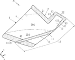
図1〜図7は、本発明の第1実施形態に係る角錐包装体を示している。本実施形態の角錐包装体A1は、包装フィルム1と被包装物5とを有しており、第1横シール部2、第2横シール部3及び縦シール部4が形成されている。
<First embodiment>
1 to 7 show a pyramid package according to a first embodiment of the present invention. The pyramid package A1 of the present embodiment has a
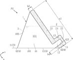
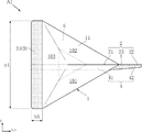
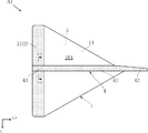
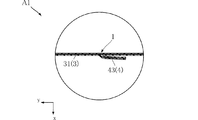
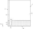
図1は、角錐包装体A1を示す斜視図である。図2は、角錐包装体A1を示す側面図である。図3は、角錐包装体A1を示す平面図である。図4は、角錐包装体A1を示す底面図である。図5は、角錐包装体A1を示す正面図である。図6は、角錐包装体A1を示す背面図である。図7は、図4のVII−VII線に沿う要部拡大断面図である。図8は、図5のVIII−VIII線に沿う要部拡大断面図である。これらの図において、x方向は、本発明の「第1方向」に相当し、y方向は、本発明の「第2方向」に相当し、z方向は、本発明の「第3方向」に相当する。また、図5においては、図2の側面図における各部との対応を明確とすべく、要部側面図が追記されている。 FIG. 1 is a perspective view showing a pyramid package A1. FIG. 2 is a side view showing the pyramid package A1. FIG. 3 is a plan view showing the pyramid package A1. FIG. 4 is a bottom view showing the pyramid package A1. FIG. 5 is a front view showing the pyramid package A1. FIG. 6 is a rear view showing the pyramid package A1. FIG. 7 is an enlarged sectional view of a main part along line VII-VII in FIG. FIG. 8 is an enlarged sectional view of a main part along line VIII-VIII in FIG. In these figures, the x direction corresponds to the “first direction” of the present invention, the y direction corresponds to the “second direction” of the present invention, and the z direction corresponds to the “third direction” of the present invention. Equivalent to. Further, in FIG. 5, a side view of a main part is added to clarify the correspondence with each part in the side view of FIG.
包装フィルム1は、角錐包装体A1を構成する主材である。包装フィルム1の構成は特に限定されず、通常、単層または複層の樹脂フィルムから構成され、シーラント層やベースフィルム層を適宜有する複層樹脂フィルムが好適に用いられる。前記シーラント層は、加熱することによって溶融し熱融着可能な層である。ガスバリア性や遮光性などのバリア性能が要求される場合には、内層にバリア層を設けることが好適である。なお、前記ベースフィルム層そのものにバリア性を付与してもよい。本実施形態においては、後述する第1横シール部2、第2横シール部3及び縦シール部4の形成を実現するため、包装フィルム1は、内面層がシーラント層、外面層がベースフィルム層によって構成されている。
The
前記シーラント層は、シール温度で熱融着可能なフィルムであれば特に限定されず、通常公知のものが用いられる。具体的には、例えば、低密度ポリエチレン(LDPE)、直鎖状低密度ポリエチレン(LLDPE)、エチレン−プロピレン共重合体(EP)、未延伸ポリプロピレン(CPP)などのオレフィン系樹脂、二軸延伸ナイロン(ON)、エチレン−オレフィン共重合体、エチレン−アクリル酸共重合体(EAA)、エチレン−メタクリル酸共重合体(EMAA)及びエチレン−酢酸ビニル共重合体(EVA)等から構成される一層又は二層以上の延伸又未延伸フィルムが挙げられ、熱融着性に特に優れていることからオレフィン系樹脂を用いることが好ましい。前記シーラント層の厚みは、例えば、30μm〜200μm程度である。 The sealant layer is not particularly limited as long as it is a film that can be heat-sealed at the sealing temperature, and a generally known film is used. Specifically, for example, olefin-based resins such as low-density polyethylene (LDPE), linear low-density polyethylene (LLDPE), ethylene-propylene copolymer (EP), unstretched polypropylene (CPP), and biaxially stretched nylon (ON), a layer composed of ethylene-olefin copolymer, ethylene-acrylic acid copolymer (EAA), ethylene-methacrylic acid copolymer (EMAA), ethylene-vinyl acetate copolymer (EVA), or the like. A stretched or unstretched film having two or more layers is exemplified, and it is preferable to use an olefin-based resin because it is particularly excellent in heat fusion property. The thickness of the sealant layer is, for example, about 30 μm to 200 μm.
前記ベースフィルム層は、前記シール温度(例えば、80℃〜110℃)で溶融または変形しないフィルムであれば特に限定されず、ポリエステル(ポリエチレンテレフタレート(PET)、ポリエチレンナフタレ−ト(PEN)、ポリブチレンテレフタレート(PBT)、ポリカーボネート(PC)など)、ポリオレフィン(ポリエチレン(PE)、ポリプロピレン(PP)など)、ポリアミド(ナイロン−6、ナイロン−66など)、ポリアクリロニトリル(PAN)、ポリイミド(PI)、ポリ塩化ビニル(PVC)、ポリ塩化ビニリデン(PVDC)、ポリメチルメタクリレート(PMMA)、及びポリエーテルスルフォン(PES)等から構成される一層又は二層以上の延伸又未延伸フィルムなどが挙げられる。また、前記ベースフィルム層は、透明または不透明の何れでもよいが、意匠印刷層をその内面側に設ける場合には、透明な前記ベースフィルム層が用いられる。前記ベースフィルム層の厚みは、例えば、10μm〜100μm程度である。 The base film layer is not particularly limited as long as it is a film that does not melt or deform at the sealing temperature (for example, 80 ° C. to 110 ° C.), and polyester (polyethylene terephthalate (PET), polyethylene naphthalate (PEN), Butylene terephthalate (PBT), polycarbonate (PC), etc., polyolefin (polyethylene (PE), polypropylene (PP), etc.), polyamide (nylon-6, nylon-66, etc.), polyacrylonitrile (PAN), polyimide (PI), One or two or more stretched or unstretched films composed of polyvinyl chloride (PVC), polyvinylidene chloride (PVDC), polymethyl methacrylate (PMMA), polyethersulfone (PES), and the like. The base film layer may be transparent or opaque, but when a design printing layer is provided on the inner surface side, the transparent base film layer is used. The thickness of the base film layer is, for example, about 10 μm to 100 μm.
前記バリア層としては、例えば、アルミニウム等の金属薄膜、又は塩化ビニリデン(PVDC)、エチレン−ビニルアルコール共重合体(EVOH)などの樹脂フィルム、或いは任意の合成樹脂フィルム(例えば、ベースフィルム層であってもよい)に、アルミニウム、酸化アルミニウムやシリカ等の無機酸化物などを蒸着(又はスパッタリング)したフィルムが挙げられる。 As the barrier layer, for example, a metal thin film such as aluminum, a resin film such as vinylidene chloride (PVDC) or ethylene-vinyl alcohol copolymer (EVOH), or an arbitrary synthetic resin film (for example, a base film layer). May be used), and a film obtained by vapor deposition (or sputtering) of an inorganic oxide such as aluminum, aluminum oxide or silica.
なお、包装フィルム1には、商品名などのデザインを表示するために、通常、意匠印刷層(図示せず)がグラビア印刷などの公知の方法により設けられている。前記意匠印刷層は、そのデザインが外部から視認できるように設けられていればよい。前記意匠印刷層は前記ベースフィルム層の外面又は内面の何れに設けてもよいが、前記意匠印刷層の傷付き防止のため、前記意匠印刷層は、ベースフィルム層の内面に設けられていることが好ましい。
The
さらに、角錐包装体A1の用途によって、包装フィルム1が水溶性材料からなることを求められる場合がある。水溶性材料としては、水溶性紙、水溶性繊維(不織布等)、水溶性樹脂が挙げられる。また、水溶性樹脂としては、天然高分子(デンプン誘導体等)、合成高分子(ポリビニルアルコール、ブテンジオール・ビニルアルコール共重合体、ポリビニルエーテル、ポリビニルピロリドン、ポリアクリル酸ソーダ、ポリアクリルアミド等)及び半合成高分子(セルロース誘導体等)等が挙げられる。より好ましい包装フィルム1の形態としては、水溶性材料から選択される少なくとも2層の積層体又は、2枚の重ね合せ体から構成されている複合体である。例えば、前記ベースフィルム層として、水溶性紙(30μ)が用いられ、前記シーラント層として水溶性ポリビニルアルコール系樹脂(15μ)が用いられる。なお、包装フィルム1が水溶性紙を含んでいる場合、例えば長尺のフィルム材料を用いて複数の角錐包装体A1を連続的に製造しやすい点、製造工程における切断等の加工が容易である点、角錐包装体A1の形態を維持しやすい点、等の利点がある。
Furthermore, depending on the use of the pyramidal package A1, the
前記ベースフィルム層の好ましい厚みは、30μm〜120μmであり、前記シーラント層の好ましい厚みは、10μm〜90μmである。前記ベースフィルム層及び前記シーラント層の厚みが厚すぎると、水への溶解が完了するまでの時間が過度にかかることが懸念される。一方、前記ベースフィルム層及び前記シーラント層の厚みが薄すぎると、角錐包装体A1の形状を維持することが困難となったり、空気中の水分の影響を受けやすくなったりするといったことが懸念される。 The preferred thickness of the base film layer is 30 μm to 120 μm, and the preferred thickness of the sealant layer is 10 μm to 90 μm. If the thicknesses of the base film layer and the sealant layer are too large, there is a concern that it takes too much time until the dissolution in water is completed. On the other hand, if the thicknesses of the base film layer and the sealant layer are too thin, it is difficult to maintain the shape of the pyramidal package A1, or there is a concern that the shape becomes susceptible to moisture in the air. You.
包装フィルム1は、第1横シール部2、第2横シール部3及び縦シール部4が形成されることにより、第1面部101、第2面部102、第3面部103及び第4面部104を有する角錐体形状とされている。第1面部101、第2面部102、第3面部103及び第4面部104は、各々が三角形状であり、例えば、二等辺三角形状、あるいは正三角形状となりうる。図示された例は、第1面部101、第2面部102、第3面部103及び第4面部104が、正三角形状である場合である。
The
第1横シール部2及び第2横シール部3は、z方向に互いに離間している。第1横シール部2は、x方向に延びる部分を有しており、第2横シール部3は、y方向に延びる部分を有している。x方向とy方向とは互いに交差している。また、x方向及びy方向はいずれも、z方向と交差している。図示された例においては、x方向、y方向及びz方向は、互いに直角である。ただし、x方向、y方向及びz方向のいずれか同士がなす角度は、90°以外であってもよい。
The first
第1横シール部2は、包装フィルム1のz方向一端部同士が例えばヒートシールによって接合された部位である。図1及び図2に示すように、本実施形態の第1横シール部2は、第1横帯部21、封止部22及び連結部23を有する。なお、これらの図においては、第1横帯部21、封止部22及び連結部23の境界を、便宜上、二点鎖線(仮想線)によって示している。
The first
第1横帯部21は、x方向に沿って延びる部分である。図示された例においては、第1横帯部21は、図2に示された包装フィルム1の図中左上端からx方向に延びる帯状の部分である。
The first
封止部22は、第1横帯部21に対してx方向の一方側である図中右下側に位置しており、図示された例においては、第1横帯部21に対してz方向の一方側である図中右上側に位置している。封止部22は、後述の吐出部12を塞ぐためのものである。封止部22の形状は特に限定されず、図示された例においては、x方向に延びる帯状である。
The sealing
連結部23は、第1横帯部21と封止部22とを繋ぐ部位である。連結部23の形状は特に限定されず、図示された例においては、z方向に延びる帯状である。
The
第2横シール部3は、包装フィルム1のz方向他端部同士が例えばヒートシールによって接合された部位である。図1及び図3に示すように、本実施形態の第2横シール部3は、第2横帯部31を有する。第2横帯部31は、y方向に沿って延びる帯状部分である。本実施形態においては、第2横帯部31は、包装フィルム1のy方向両端に到達している。なお、第2横シール部3は、y方向に延びる部分を少なくとも有するものであればよく、第2横帯部31以外の部分を有する形状であってもよく、種々の曲線形状、屈曲形状、波線形状等の形状が適宜採用されてもよい。
The second
縦シール部4は、後述の収容部11を縦断するように形成されている。図1、図2及び図4に示すように、本実施形態においては、縦シール部4は、縦帯部41、第1端部42及び第2端部43を有する。また、図7に示すように、本実施形態の縦シール部4は、包装フィルム1の内面同士が例えばヒートシールによって接合された、所謂合掌貼りの接合形態とされている。
The
縦帯部41は、図1及び図4に示すように、第1横シール部2と第2横シール部3との間に位置しており、収容部11を横断している。
The
第1端部42は、図1及び図2に示すように、第1横シール部2と吐出部12を挟んでx方向に並んで配置されており、包装フィルム1のx方向一端に位置している。第1端部42は、第3方向に沿って延びている。第1端部42は、内端縁421を有する。内端縁421は、吐出部12を規定する端縁である。内端縁421は、z方向に対して平行であるか、またはz方向において収容部11から離間するほど(図2において右斜め上に向かうほど)x方向において第1横シール部2に近づくようにx方向に対して傾いている。図示された例においては、内端縁421は、x方向に対して平行である。
As shown in FIGS. 1 and 2, the
第2端部43は、図1、図4及び図7に示すように、第2横シール部3のy方向両端から離間した部分に繋がる。本実施形態においては、第2端部43は、第2横シール部3のy方向における略中央部分に繋がっている。第2端部43は、z方向に延びる帯状である。
As shown in FIGS. 1, 4 and 7, the
本実施形態においては、縦帯部41の幅は、全長にわたって一定であり、第2端部43の幅は、全長にわたって一定であり、縦帯部41の幅と同じである。また、図示された例においては、第1端部42の幅は全長にわたって一定であり、縦帯部41及び第2端部43の幅と同じである。一方、図示された例とは異なり、内端縁421がz方向において収容部11から離間するほど(図2において右斜め上に向かうほど)x方向において第1横シール部2に近づくようにx方向に対して傾いている場合、第1端部42の少なくとも一部の幅は、縦帯部41及び第2端部43の幅よりも大きいものとなる。したがって、第1端部42の幅は、縦帯部41及び第2端部43の幅と同じであるか、または縦帯部41及び第2端部43の幅よりも大きい。
In the present embodiment, the width of the
包装フィルム1は、通常、屈曲等が可能な樹脂フィルムからなる。このため、第1横シール部2、第2横シール部3及び縦シール部4の各部は、様々な方向を向くように起立したり寝かしたりすることが可能である。
The
本実施形態においては、図2及び図3に示すように、第2横帯部31(第2横シール部3)は、y方向に対して平行であり、第4面部104と略面一となる方向に沿っている。また、本実施形態においては、第1横帯部21、封止部22及び連結部23は、図3及び図5に示すように、x方向及びz方向に対して略平行であり、y方向に対して略直角である。
In this embodiment, as shown in FIGS. 2 and 3, the second horizontal band portion 31 (the second horizontal seal portion 3) is parallel to the y direction, and is substantially flush with the
図1及び図6に示すように、第2端部43は、第2横帯部31(第2横シール部3)に沿うように寝かされており、y方向となす角度が極めて小さい角度である。また、縦帯部41のうち第2端部43に繋がる部分を含む大部分は、図4に示すように、第4面部104に沿うように寝かされており、また、第1端部42は、図1及び図2に示すように、z方向に沿って延びている。ただし、図3、図5及び図8に示すように、第1端部42は、x方向に対して傾いている。
As shown in FIGS. 1 and 6, the
収容部11は、被包装物5を収容する部位であり、第1面部101、第2面部102、第3面部103及び第4面部104によって規定されている。収容部11は、第1横シール部2と第2横シール部3との間に設けられている。収容部11は、第1横シール部2、第2横シール部3及び縦シール部4によって密閉されている。
The
吐出部12は、図2に示すように、収容部11に繋がっており、縦シール部4の第1端部42に沿ってz方向に突出する。図示された例においては、吐出部12は、縦シール部4の第1端部42、第1横シール部2の封止部22及び連結部23によって形状が規定されている。また、図5及び図8から理解されるように、少なくとも角錐包装体A1が未開封の状態においては、吐出部12は、包装フィルム1のうちy方向に対して略直角である2つの部分(x方向及びz方向に対して略平行である2つの部分)同士が、非接合の状態で対面した部位である。図示された例においては、吐出部12は、x方向における幅が略一定とされている。
As shown in FIG. 2, the
図2に示すように、図示された例においては、包装フィルム1には、切断起点部13が形成されている。切断起点部13は、吐出部12を横断する切断の起点となる部位である。切断起点部13の具体的構成は特に限定されず、例えば切れ目線(短い切断線)やミシン目線、三角形状等の切り欠き部によって構成される。なお、これらの切断起点部13は、収容部11や吐出部12の気密状態を維持すべく、第1横シール部2や縦シール部4に設けられることが好ましい。
As shown in FIG. 2, in the illustrated example, the
図示された例においては、各々が切れ目線からなる2つの切断起点部13が、吐出部12を挟んでx方向両側に設けられている。一方の切断起点部13は、第1横シール部2の連結部23に設けられている。他方の切断起点部13は、縦シール部4の第1端部42に設けられている。
In the illustrated example, two cutting
包装フィルム1の大きさや収容部11の容積は特に限定されないが、収容部11の容積は、100mL以下が好ましく、さらに好ましくは50mL以下である。また、第1横シール部2の長さx1(図2における第1横シール部2のx方向寸法)及び第2横シール部3の長さy1(図3における第2横シール部3のy方向寸法)と縦シール部4の長さz1(図1参照)との比は、1:1〜1:1.5が好ましく、さらに好ましくは、1:1.1〜1:1.2である。
The size of the
包装フィルム1の具体例を挙げると、収容部11の容量が30mLの場合に、長さx1及び長さy1が65mm、長さz1が76mmである。また、図2に示す第1横シール部2の幅b2(z方向寸法)、図3に示す第2横シール部3の幅b3(z方向寸法)及び図2に示す縦シール部4の幅(図中第1端部42のx方向寸法)は、いずれも5mmである。
To give a specific example of the
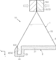
次に、角錐包装体A1の製造方法の一例について、図9〜図12を参照しつつ以下に説明する。これらの図に示された製造方法は、1つの角錐包装体A1を個別に製造する方法であるが、角錐包装体A1の製造方法は特に限定されない。 Next, an example of a method for manufacturing the pyramid package A1 will be described below with reference to FIGS. The manufacturing method shown in these figures is a method for manufacturing one pyramid package A1 individually, but the method for manufacturing the pyramid package A1 is not particularly limited.
まず、図9に示すように、包装フィルム1を用意する。包装フィルム1は、z方向を軸方向とする筒状である。包装フィルム1は、例えば1枚のフィルム材料のx方向両端部の内面同士をヒートシールすることで合掌貼りとされた縦シール部4を設けることにより形成される。同図は、包装フィルム1が、z方向及びx方向に沿う扁平な形状に折り畳まれた状態を示しており、z方向における図中上方及び下方が開口している。
First, as shown in FIG. 9, the
次いで、図10に示すように、中間シール部20を形成する。中間シール部20の形成は、包装フィルム1のz方向図中下端部同士の内面をヒートシールによって接合することにより行う。図示された中間シール部20の形成においては、縦シール部4のうち第1端部42となるべき部分と重なるようにヒートシールがなされている。なお、図示された例とは異なり、例えば、図9の縦シール部4が包装フィルム1のz方向下端に到達しない構成である場合に、中間シール部20の形成するためのヒートシールによって第1端部42の全体を形成してもよい。同図においては、このヒートシールの境界線を実線で示しているが、角錐包装体A1を示す各図においては、便宜上省略している。中間シール部20は、吐出部12を塞ぐ封止部22となるべき部分と、封止部22よりもz方向寸法が大きくx方向に延びる広幅の部分とを有しているが、これは、中間シール部20の一例であり、特に限定されない。中間シール部20の形成により、包装フィルム1のz方向下端が密閉される。なお、上述した具体例のように、幅b2が5mmである第1横シール部2を製造する場合、中間シール部20の幅(z方向寸法)は、例えば20mm程度である。
Next, as shown in FIG. 10, an
次いで、図11に示すように、中間シール部20を切断することにより、第1横帯部21、封止部22及び連結部23を有する第1横シール部2を形成する。なお、中間シール部20を形成する手法に代えて、予め所定形状に切断された包装フィルム1を用いて、第1横シール部2を直接形成してもよい。次いで、包装フィルム1のz方向上端を拡開し、例えばノズルNzを包装フィルム1の収容部11に挿入する。そして、ノズルNzから所定量の被包装物5を収容部11内に充填する。
Next, as shown in FIG. 11, by cutting the
次いで、図12に示すように、包装フィルム1のz方向上端部を、x方向両端同士が近づくように変形させる。そして、包装フィルム1のz方向上端部を、例えばヒート金型Mdによって挟み、所定温度まで加熱する。これにより、包装フィルム1のz方向上端部の内面同士がヒートシールによって接合され、第2横帯部31(第2横シール部3)が形成される。なお、第2横帯部31(第2横シール部3)の形成においては、縦シール部4のz方向上端部分が、ヒート金型Mdによって挟まれ、第2端部43となり、縦シール部4のうち第1端部42と第2端部43との間の部分が縦帯部41となる。第2端部43は、第2横帯部31(第2横シール部3)に沿うようにこれにより、角錐包装体A1が完成する。なお、図12に示す工程を行うと、第2端部43が、第2横シール部3に沿って寝かされた状態となり、これに伴い、縦帯部41が第4面部104に沿って寝かされた状態となり、さらに、図8に示したように、第1端部42がx方向に対して傾いた状態となる。この第1端部42が傾くことは、第1横シール部2をx方向及びz方向に沿って起立させておくことに寄与している。
Next, as shown in FIG. 12, the upper end in the z direction of the
なお、角錐包装体A1の製造方法の好ましい手法として、複数の包装フィルム1を形成可能な長尺の筒状フィルム材料を用いて、複数の角錐包装体A1を連続的に順次製造する方法が挙げられる。この場合、例えば図9に示す包装フィルム1に変えて、z方向にさらに長く延びるフィルム材料を用いる。このフィルム材料のx方向両端を一括して、または連続的にヒートシールによって接合することにより、z方向に長く延びる縦シール部4を形成する。上述した通り、角錐包装体A1の縦シール部4は、第1端部42の幅が、縦帯部41及び第2端部43の幅と同じであるか、または縦帯部41及び第2端部43の幅よりも大きい。このため、角錐包装体A1の製造においては、例えば第1端部42及び第2端部43の幅と同じ一定幅のz方向に長く延びるシール部を形成することにより、縦シール部4を形成することができる。
In addition, as a preferable method of the manufacturing method of the pyramid packaging body A1, a method of continuously manufacturing a plurality of pyramid packaging bodies A1 sequentially using a long tubular film material capable of forming a plurality of
次いで、図10に示す中間シール部20を形成する。なお、第1端部42の少なくとも一部の幅が、縦帯部41及び第2端部43の幅よりも大きい構成の場合、一定幅の縦シール部4を形成した後に、中間シール部20の形成において、第1端部42の拡幅部分を形成すればよい。次いで、図11に示す被包装物5の充填及び図12に示す第2横シール部3の形成を順次行う。そして、フィルム材料の適所(中間シール部20及び第2横シール部3)の切断を行うことにより、角錐包装体A1が得られる。この後は、例えば、図12に示す第2横シール部3の形成に伴って、フィルム材料のうちy方向に沿って畳まれた部分を、x方向に沿って平坦となるように変形させる。そして、図10に示す中間シール部20の形成以降の処理を繰り返すことにより、複数の角錐包装体A1を連続的に順次製造することができる。
Next, the
このような手法によれば、それぞれが概ね単一の方向に沿った形状である縦シール部4、第1横シール部2(中間シール部20)及び第2横シール部3の形成をそれぞれ別の工程で行えばよく、例えば縦シール部4と第1横シール部2とが一体となった略L字状等の複雑な形状のシール部を形成することは不要である。したがって、角錐包装体A1の製造をより容易により効率よく行うことができる。また、第1端部42の幅が、縦帯部41及び第2端部43の幅と同じであるか、または縦帯部41及び第2端部43の幅よりも大きいことにより、z方向に延びる一定幅のシール部を利用して、縦シール部4を形成することができる。本実施形態とは異なり、第1端部42が、縦帯部41及び第2端部43よりも幅が狭い部分を有する場合、z方向に延びる一定幅のシール部を形成する手法を採用することは困難であり、例えば一定幅のシール部と、部分的に狭幅であるシール部とを、交互に形成するといった手法が強いられる。本実施形態によれば、このような煩雑な工程は不要であり、複数の角錐包装体A1を効率よく製造するのに好適である。
According to such a method, the formation of the
次に、角錐包装体A1の作用について説明する。 Next, the operation of the pyramid package A1 will be described.
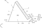
図13は、角錐包装体A1の開封を示している。角錐包装体A1の開封は、2つの切断起点部13のいずれかを起点として、吐出部12をx方向に横断するように包装フィルム1を切断することにより行う。この開封により、包装フィルム1には、吐出口120が形成される。吐出口120は、吐出部12のz方向一端に位置する開口部分である。
FIG. 13 shows opening of the pyramid package A1. The opening of the pyramid package A1 is performed by cutting the
図14は、角錐包装体A1からの被包装物5の吐出を示している。図13に示した開封の後に、例えば3本の指Fgによって第1面部101、第2面部102及び第3面部103を押圧する。これにより、収容部11の容積が縮小し、被包装物5が吐出部12の吐出口120から吐出される。吐出部12は、第1端部42の内端縁421に沿っている。内端縁421は、z方向に対して平行であるか、またはz方向において収容部11から離間するほど(図2において右斜め上に向かうほど)x方向において第1横シール部2に近づくようにx方向に対して傾いており、図示された例においては、z方向に対して平行である。これにより、第1端部42の先端のx方向における幅は、z方向根元部分(縦帯部41側部分)の幅と同程度であり、第1端部42の先端の幅が狭くなることによる剛性低下を抑制可能である。このため、吐出部12から被包装物5を吐出する際に吐出部12が意図せずふらついてしまうこと等を抑制することができる。したがって、本実施形態によれば、所望の方向に被包装物5を吐出させることができる。
FIG. 14 shows the discharge of the article to be packaged 5 from the pyramid package A1. After the opening shown in FIG. 13, the
また、図5に示すように、連結部23及び包装フィルム1のうち吐出部12を構成する部分は、x方向及びz方向に沿っている。一方、図8に示すように、第1端部42は、z方向に沿った形状ではあるものの、x方向に対して傾いている。これにより、封止部22、包装フィルム1のうち吐出部12を構成する部分及び第1端部42は、z方向に沿った屈曲断面の部位を構成している。このような屈曲断面の部位は、平坦な断面の部位と比べて剛性が高く、z方向に沿った姿勢をより確実に維持しうる。これは、吐出部12の吐出口120からz方向に向けて被包装物5を吐出するのに好ましい。
In addition, as shown in FIG. 5, portions of the connecting
例えば、第4面部104を鉛直方向に対して略垂直となるように、鉛直方向最下方に位置させた姿勢では、吐出部12(z方向)は、第4面部104に対して斜め上を向く。この状態で吐出を行うと、吐出部12から被包装物5を斜め上に向けて吐出させることが可能である。このような吐出は、例えば、洋式便器の清掃において、縁部の内側に斜め下から斜め上に向かって洗剤を吐出させるのに適している。また、図14に示すように、吐出部12は、第4面部104に隣接している。このため、第4面部104が鉛直方向最下方に位置すると、収容部11内の被包装物5は、吐出される過程においても吐出部12の近傍に存在し続ける。したがって、包装フィルム1を押圧する動作を継続することのみによって収容部11内の被包装物5のほとんどを吐出することが可能であり、吐出の最中に角錐包装体A1の向きを変更する等の必要がない。
For example, in a posture in which the
さらに、包装フィルム1が水溶性材料からなる構成によれば、清掃に用いる洗剤を所望の箇所に吐出した後に、便器内に貯められた水に包装フィルム1を速やかに投入することができる。これにより、洗剤の包装フィルム1を、別の場所のゴミ箱等に投入する必要がなく、清掃等の利便性を向上させることができる。また、四面体を構成する角錐包装体A1は、例えば長尺筒状の包装体と比べて、容積に対する表面積の割合が小さい。これにより、所定量の洗剤等の被包装物5を包装するために要する包装フィルム1の使用量を削減することが可能である。
Further, according to the configuration in which the
角錐包装体A1は、開封前の状態においては、封止部22を有することにより収容部11は密閉されている。このため、被包装物5の変質や漏洩等を抑制することができる。また、包装フィルム1には、切断起点部13が形成されている。このため、吐出部12をx方向に縦断するように、包装フィルム1をより容易に切断することができる。
Before the pyramid package A1 is opened, the
第1横シール部2は、連結部23を有する。連結部23は、x方向において吐出部12を挟んで第1端部42とは反対側に位置しており、z方向に沿った形状である。これにより、被包装物5を吐出する際に、吐出部12をより確実にz方向に沿わせることができる。
The first
上記の具体例として示した大きさの包装フィルム1を備えた角錐包装体A1では、収容部11が比較的小容量であり、角錐包装体A1全体が小型である。このため、包装フィルム1の剛性が高く、開封前及び開封後において、包装フィルム1が四面体の外形をより強固に維持しうる。したがって、例えば開封後に使用者の意に反して、包装フィルム1が変形し被包装物5が漏れ出してしまうこと等を抑制することができる。また、図14に示したように、開封後に被包装物5を吐出させる際に、片手のみの指Fgによって、包装フィルム1を確実に押圧し、被包装物5をより容易に絞り出すことができる。さらに、このような小型の角錐包装体A1において、図5及び図8に示すように第1端部42が第1横シール部2に近づくようにx方向に対して傾いていることにより、吐出部12をz方向に沿った姿勢により確実に維持するように剛性が顕著に高められる。これは、被包装物5を所望の方向に確実に吐出するのに好ましい。
In the pyramid package A1 provided with the
図15〜図17は、本発明の変形例及び他の実施形態を示している。なお、これらの図において、上記実施形態と同一または類似の要素には、上記実施形態と同一の符号を付している。 15 to 17 show modified examples and other embodiments of the present invention. In these drawings, the same or similar elements as those in the above embodiment are denoted by the same reference numerals as those in the above embodiment.
<第1実施形態 第1変形例>
図15は、角錐包装体A1の第1変形例を示す要部側面図である。本変形例の角錐包装体A11は、吐出部12のx方向における幅が、z方向において収容部11から離間するほど狭くなる形状とされている。具体的には、吐出部12の第1端部42側の端縁(内端縁421)は、z方向に略平行であり、連結部23側の端縁は、z方向に対して傾いている。このような変形例によっても、吐出部12から被包装物5をz方向に向けて吐出することができる。また、吐出部12の先端のx方向における幅が狭くなっていることにより、被包装物5をより細く、より速く吐出することが可能である。
<First Embodiment First Modification>
FIG. 15 is a main part side view showing a first modification of the pyramid package A1. The pyramid package A11 of the present modification has a shape in which the width of the
<第1実施形態 第2変形例>
図16は、角錐包装体A1の第2変形例を示す要部側面図である。本変形例の角錐包装体A12は、角錐包装体A11と同様に、吐出部12のx方向における幅が、z方向において収容部11から離間するほど狭くなる形状とされている。具体的には、吐出部12の第1端部42側の端縁(内端縁421)及び連結部23側の端縁の双方が、z方向に対して傾いている。すなわち、内端縁421は、z方向において収容部11から離間するほどx方向において第1横シール部2に近づくようにz方向に対して傾いている。
<First Embodiment Second Modification>
FIG. 16 is a main part side view showing a second modification of the pyramid package A1. Similar to the pyramid package A11, the pyramid package A12 of the present modification has a shape in which the width of the
このような変形例によっても、吐出部12から被包装物5をz方向に向けて吐出することが可能であり、被包装物5をより細く、より速く吐出することが可能である。また、角錐包装体A11,A12から理解されるように、吐出部12は、全体としてz方向に沿って収容部11から突出した形状であればよく、z方向全長に渡ってx方向における幅が一定であるものに限定されない。
According to such a modified example, the packaged
<第2実施形態>
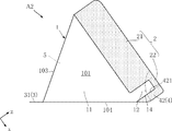
図17は、本発明の第2実施形態に係る角錐包装体を示す側面図である。本実施形態の角錐包装体A2は、第1横シール部2の構成が上述した実施形態と異なっている。
<Second embodiment>
FIG. 17 is a side view showing a pyramid package according to the second embodiment of the present invention. The configuration of the first
本実施形態の第1横シール部2は、第1横帯部21及び封止部22を有している。第1横帯部21は、角錐包装体A1の第1横帯部21と比べてz方向寸法が大きい。第1横帯部21のz方向端縁と、封止部22のz方向端縁とは、略同一直線状に位置する。第1横帯部21と封止部22は、互いに繋がっている。このような第1横シール部2は、図10に示す中間シール部20に、目立った切断を行わない場合に形成される。
The first
また、本実施形態においては、包装フィルム1に切断予定線14が形成されている。切断予定線14は、包装フィルム1の切断をより容易に行えるように、包装フィルム1に所定の加工が施された線である。切断予定線14は、吐出部12を横断しており、一端が第1端部42のx方向端縁に到達し、他端が第1横帯部21のz方向端縁に到達する曲線状である。切断予定線14の具体的構成は特に限定されず、たとえば、包装フィルム1がベースフィルム層及びシーラント層からなる場合に、ベースフィルム層のみにミシン目線を設けることにより形成することができる。
In the present embodiment, the
本実施形態によっても、所望の方向に被包装物5を吐出することができる。また、本実施形態から理解されるように、第1横シール部2の具体的な構成は特に限定されない。また、切断予定線14が上述した曲線状であることにより、第1端部42のx方向端縁から吐出部12を横断して第1横帯部21のz方向端縁に到達するように、包装フィルム1を切断することが可能である。なお、包装フィルム1には、切断起点部13及び切断予定線14のいずれか一方または双方が形成されていてもよい。あるいは、包装フィルム1には、切断起点部13及び切断予定線14のいずれもが形成されていなくてもよい。この場合、例えば、包装フィルム1に切断の目安となるように、切断箇所を示す印刷を施してもよい。
According to the present embodiment as well, the article to be packaged 5 can be discharged in a desired direction. Further, as understood from the present embodiment, the specific configuration of the first
本発明に係る角錐包装体は、上述した実施形態に限定されるものではない。本発明に係る角錐包装体の各部の具体的な構成は、種々に設計変更自在である。 The pyramid package according to the present invention is not limited to the embodiment described above. The specific configuration of each part of the pyramidal package according to the present invention can be variously changed in design.
A1,A11,A12:角錐包装体
A2 :角錐包装体
1 :包装フィルム
2 :第1横シール部
3 :第2横シール部
4 :縦シール部
5 :被包装物
11 :収容部
12 :吐出部
13 :切断起点部
14 :切断予定線
20 :中間シール部
21 :第1横帯部
22 :封止部
23 :連結部
31 :第2横帯部
41 :縦帯部
42 :第1端部
421 :内端縁
43 :第2端部
101 :第1面部
102 :第2面部
103 :第3面部
104 :第4面部
120 :吐出口
Fg :指
Md :ヒート金型
Nz :ノズル
A1, A11, A12: Pyramidal package A2: Pyramidal package 1: Packaging film 2: First horizontal seal part 3: Second horizontal seal part 4: Vertical seal part 5: Packaged object 11: Housing part 12: Discharge part 13: Cutting start part 14: Planned cutting line 20: Intermediate seal part 21: First horizontal band part 22: Sealing part 23: Connecting part 31: Second horizontal band part 41: Vertical band part 42: First end part 421 : Inner edge 43: second end 101: first surface 102: second surface 103: third surface 104: fourth surface 120: discharge port Fg: finger Md: heat mold Nz: nozzle
Claims (6)
前記収容部に収容された被包装物と、を備える角錐包装体であって、
前記縦シール部は、前記包装フィルムの内面同士が接合された部位であり、
前記縦シール部は、前記第1横シール部と前記第1方向に並んで前記第1方向一端に位置し且つ前記第3方向に延びる第1端部を含み、
前記第1端部の内端縁は、前記第3方向に対して平行であるか、または前記第3方向において前記収容部から離間するほど前記第1方向において前記第1横シール部に近づくように前記第3方向に対して傾いており、
前記包装フィルムには、前記収容部に繋がり且つ前記縦シール部の前記第1端部の前記内端縁に沿って前記第3方向に突出する吐出部が形成されていることを特徴とする、角錐包装体。 A first transverse seal portion having a portion extending in a first direction, a first transverse seal portion having a portion extending in a second direction intersecting the first direction, and the first transverse seal portion in a third direction intersecting the first direction and the second direction; A package formed with a second horizontal seal portion separated from the horizontal seal portion, a storage portion set between the first horizontal seal portion and the second horizontal seal portion, and a vertical seal portion for vertically cutting the storage portion. Film and
And a packaged object stored in the storage section,
The vertical sealing portion is a portion where the inner surfaces of the packaging film are joined to each other,
The vertical seal portion includes a first end portion that is located at one end in the first direction and extends in the third direction along with the first horizontal seal portion in the first direction,
An inner edge of the first end is parallel to the third direction, or is closer to the first horizontal seal portion in the first direction as the distance from the accommodation portion in the third direction increases. At an angle to the third direction,
The packaging film is formed with a discharge portion that is connected to the storage portion and protrudes in the third direction along the inner edge of the first end of the vertical seal portion. Pyramid packaging.
Priority Applications (1)
| Application Number | Priority Date | Filing Date | Title |
|---|---|---|---|
| JP2018130406A JP2020007012A (en) | 2018-07-10 | 2018-07-10 | Pyramid packaging |
Applications Claiming Priority (1)
| Application Number | Priority Date | Filing Date | Title |
|---|---|---|---|
| JP2018130406A JP2020007012A (en) | 2018-07-10 | 2018-07-10 | Pyramid packaging |
Publications (1)
| Publication Number | Publication Date |
|---|---|
| JP2020007012A true JP2020007012A (en) | 2020-01-16 |
Family
ID=69150256
Family Applications (1)
| Application Number | Title | Priority Date | Filing Date |
|---|---|---|---|
| JP2018130406A Pending JP2020007012A (en) | 2018-07-10 | 2018-07-10 | Pyramid packaging |
Country Status (1)
| Country | Link |
|---|---|
| JP (1) | JP2020007012A (en) |
Citations (8)
| Publication number | Priority date | Publication date | Assignee | Title |
|---|---|---|---|---|
| JPS585962U (en) * | 1981-07-01 | 1983-01-14 | 高吉 勉 | Paper bags that instantly dissolve in water |
| JPH0390874U (en) * | 1989-12-29 | 1991-09-17 | ||
| JP2000072155A (en) * | 1998-08-31 | 2000-03-07 | Dainippon Printing Co Ltd | Tetrahedral pouch packaging |
| JP2006111275A (en) * | 2004-10-12 | 2006-04-27 | Kishimoto Sangyo Co Ltd | Spout pack made of synthetic resin |
| JP2007022653A (en) * | 2005-07-19 | 2007-02-01 | Keipakku:Kk | Tetrahedral package |
| US20070099784A1 (en) * | 2003-12-23 | 2007-05-03 | Alcan Technology And Management Ltd. | Process for manufacturing a pouch-type form of packaging |
| JP2008050048A (en) * | 2006-08-28 | 2008-03-06 | Rengo Co Ltd | Twist-opening bag |
| US20120002906A1 (en) * | 2009-03-09 | 2012-01-05 | Amcor Flexibles Kreuzlingen Ltd. | Packaging bag |
-
2018
- 2018-07-10 JP JP2018130406A patent/JP2020007012A/en active Pending
Patent Citations (8)
| Publication number | Priority date | Publication date | Assignee | Title |
|---|---|---|---|---|
| JPS585962U (en) * | 1981-07-01 | 1983-01-14 | 高吉 勉 | Paper bags that instantly dissolve in water |
| JPH0390874U (en) * | 1989-12-29 | 1991-09-17 | ||
| JP2000072155A (en) * | 1998-08-31 | 2000-03-07 | Dainippon Printing Co Ltd | Tetrahedral pouch packaging |
| US20070099784A1 (en) * | 2003-12-23 | 2007-05-03 | Alcan Technology And Management Ltd. | Process for manufacturing a pouch-type form of packaging |
| JP2006111275A (en) * | 2004-10-12 | 2006-04-27 | Kishimoto Sangyo Co Ltd | Spout pack made of synthetic resin |
| JP2007022653A (en) * | 2005-07-19 | 2007-02-01 | Keipakku:Kk | Tetrahedral package |
| JP2008050048A (en) * | 2006-08-28 | 2008-03-06 | Rengo Co Ltd | Twist-opening bag |
| US20120002906A1 (en) * | 2009-03-09 | 2012-01-05 | Amcor Flexibles Kreuzlingen Ltd. | Packaging bag |
Similar Documents
| Publication | Publication Date | Title |
|---|---|---|
| JP2012025453A (en) | Packaging bag | |
| JP6830842B2 (en) | Pouch | |
| US20090134185A1 (en) | Pouch for Refill of Contents | |
| JP5428647B2 (en) | Stick packaging bag | |
| JP2009248986A (en) | Gusset bag | |
| WO2012090536A1 (en) | Pouch container | |
| JP6345416B2 (en) | Pouch container | |
| JP5887694B2 (en) | Method for manufacturing a horizontal gusset bag with an opening at the top | |
| JP2017178406A (en) | Container and package and method for producing container and package | |
| WO2015087825A1 (en) | Pouch container and method for manufacturing pouch container | |
| KR20150066529A (en) | Refillable container | |
| WO2019187723A1 (en) | Packaging body | |
| JP5782748B2 (en) | Refill container | |
| JP5516121B2 (en) | Refill container and method for manufacturing the same | |
| WO2021125026A1 (en) | Pouch-container packaging material and pouch-container packaging body | |
| JP4127424B2 (en) | Free-standing packaging bag | |
| JP5463560B2 (en) | Refillable pouch | |
| JP6131066B2 (en) | Pouch container | |
| WO2022004542A1 (en) | Packaging bag | |
| JP5022988B2 (en) | Bag container | |
| JP5396635B2 (en) | Soft packaging container | |
| JP2019059535A (en) | Container package body | |
| JP7775587B2 (en) | packaging bag | |
| JP2016098035A (en) | Packaging bag with fastener | |
| JP6712158B2 (en) | Pouch container and manufacturing method thereof |
Legal Events
| Date | Code | Title | Description |
|---|---|---|---|
| A621 | Written request for application examination |
Free format text: JAPANESE INTERMEDIATE CODE: A621 Effective date: 20210618 |
|
| A977 | Report on retrieval |
Free format text: JAPANESE INTERMEDIATE CODE: A971007 Effective date: 20220519 |
|
| A131 | Notification of reasons for refusal |
Free format text: JAPANESE INTERMEDIATE CODE: A131 Effective date: 20220524 |
|
| A02 | Decision of refusal |
Free format text: JAPANESE INTERMEDIATE CODE: A02 Effective date: 20221122 |