JP2020007152A - Garbage bag unit, garbage bag positioning mechanism and smart garbage bin - Google Patents
Garbage bag unit, garbage bag positioning mechanism and smart garbage bin Download PDFInfo
- Publication number
- JP2020007152A JP2020007152A JP2019088287A JP2019088287A JP2020007152A JP 2020007152 A JP2020007152 A JP 2020007152A JP 2019088287 A JP2019088287 A JP 2019088287A JP 2019088287 A JP2019088287 A JP 2019088287A JP 2020007152 A JP2020007152 A JP 2020007152A
- Authority
- JP
- Japan
- Prior art keywords
- trash
- garbage bag
- opening
- garbage
- bag
- Prior art date
- Legal status (The legal status is an assumption and is not a legal conclusion. Google has not performed a legal analysis and makes no representation as to the accuracy of the status listed.)
- Pending
Links
Images




Classifications
-
- B—PERFORMING OPERATIONS; TRANSPORTING
- B65—CONVEYING; PACKING; STORING; HANDLING THIN OR FILAMENTARY MATERIAL
- B65F—GATHERING OR REMOVAL OF DOMESTIC OR LIKE REFUSE
- B65F1/00—Refuse receptacles; Accessories therefor
- B65F1/04—Refuse receptacles; Accessories therefor with removable inserts
- B65F1/06—Refuse receptacles; Accessories therefor with removable inserts with flexible inserts, e.g. bags or sacks
- B65F1/065—Refuse receptacles; Accessories therefor with removable inserts with flexible inserts, e.g. bags or sacks with means aiding the insertion of the flexible insert
-
- B—PERFORMING OPERATIONS; TRANSPORTING
- B65—CONVEYING; PACKING; STORING; HANDLING THIN OR FILAMENTARY MATERIAL
- B65F—GATHERING OR REMOVAL OF DOMESTIC OR LIKE REFUSE
- B65F1/00—Refuse receptacles; Accessories therefor
- B65F1/04—Refuse receptacles; Accessories therefor with removable inserts
- B65F1/06—Refuse receptacles; Accessories therefor with removable inserts with flexible inserts, e.g. bags or sacks
- B65F1/062—Refuse receptacles; Accessories therefor with removable inserts with flexible inserts, e.g. bags or sacks having means for storing or dispensing spare bags
-
- B—PERFORMING OPERATIONS; TRANSPORTING
- B65—CONVEYING; PACKING; STORING; HANDLING THIN OR FILAMENTARY MATERIAL
- B65F—GATHERING OR REMOVAL OF DOMESTIC OR LIKE REFUSE
- B65F1/00—Refuse receptacles; Accessories therefor
- B65F1/14—Other constructional features; Accessories
- B65F1/16—Lids or covers
-
- B—PERFORMING OPERATIONS; TRANSPORTING
- B65—CONVEYING; PACKING; STORING; HANDLING THIN OR FILAMENTARY MATERIAL
- B65F—GATHERING OR REMOVAL OF DOMESTIC OR LIKE REFUSE
- B65F1/00—Refuse receptacles; Accessories therefor
- B65F1/14—Other constructional features; Accessories
- B65F2001/1653—Constructional features of lids or covers
-
- B—PERFORMING OPERATIONS; TRANSPORTING
- B65—CONVEYING; PACKING; STORING; HANDLING THIN OR FILAMENTARY MATERIAL
- B65F—GATHERING OR REMOVAL OF DOMESTIC OR LIKE REFUSE
- B65F2210/00—Equipment of refuse receptacles
- B65F2210/167—Sealing means
-
- B—PERFORMING OPERATIONS; TRANSPORTING
- B65—CONVEYING; PACKING; STORING; HANDLING THIN OR FILAMENTARY MATERIAL
- B65F—GATHERING OR REMOVAL OF DOMESTIC OR LIKE REFUSE
- B65F2210/00—Equipment of refuse receptacles
- B65F2210/188—Vacuum drawing means
Landscapes
- Engineering & Computer Science (AREA)
- Mechanical Engineering (AREA)
- Refuse Receptacles (AREA)
Abstract
Description
本発明は、スマートゴミ箱の技術分野に関し、より具体的には、ゴミ袋ユニット、ゴミ袋ユニット位置決め機構およびスマートゴミ箱に関する。 The present invention relates to the technical field of smart trash cans, and more specifically, to a trash bag unit, a trash bag unit positioning mechanism, and a smart trash can.
科学技術の発展と人々の生活水準の向上に伴い、スマートホームは次第に日常生活の一部として欠かせなくなってきている。中でも、スマートゴミ箱は、清潔かつ衛生的で、便利に使用できるという特徴により、人々の注目を集めている。 With the development of science and technology and the improvement of people's living standards, smart homes are becoming increasingly indispensable as part of everyday life. Among them, smart trash cans are attracting people's attention because of their clean, sanitary, and convenient use.
従来技術において、スマートゴミ箱の自動化のレベルはますます高まっているが、全自動での装着および包装技術は未だ完全ではない。その原因は、ゴミ袋の全自動での装着および包装技術が、自動装着装置、自動包装装置、自動装着および自動包装に適したゴミ袋、ゴミ袋収納装置などの様々な構成要素の組み合わせに依存していることであり、この中のどの要素が不完全であっても、ゴミ袋の全自動での装着および包装を実現することはできない。 In the prior art, the level of automation of smart trash cans is increasing, but the technology of fully automatic mounting and packaging is not yet complete. The cause is that the fully automatic loading and packaging technology of garbage bags depends on the combination of various components such as automatic loading device, automatic packaging device, garbage bag suitable for automatic loading and automatic packaging, garbage bag storage device, etc. Therefore, even if any of these elements are incomplete, it is not possible to realize automatic mounting and packaging of the garbage bag.
ゴミ袋に関しては、現在市販されている一般的ないくつかの種類のゴミ袋の形態としては、取手なしゴミ袋、手提げタイプのゴミ袋、ひも付きゴミ袋などがあり、その包装形態の多くがロール状であるが、一部の手提げタイプのゴミ袋は平たく折り畳まれた包装を用いており、さらに、少数のゴミ袋の中には1枚ずつ取り出すタイプの包装を用いているものもある。それらに共通する特徴としては、包装の体積が小さく、製造コストが低いことが挙げられるが、プラスチック製ゴミ袋は柔軟性が高いため、簡易な機械ではゴミ袋の取り出しや装着を実現することができず、手作業で交換用のゴミ袋をゴミ箱に被せなければ新しいゴミ袋の装着を完了できないという欠点がある。また、ゴミ袋の内部容量は一定であるため、ゴミ袋の包装要件を満たすために、通常、内部のゴミの封入量はゴミ袋の容量より少なくなる。一般的なゴミ袋では、袋の口を閉じるためには2/3の容量しかゴミを封入することができないため、ゴミの廃棄に不利であり、清掃員がゴミを処理する際にゴミが散らばりやすく、環境に悪影響を及ぼす。また、ゴミ袋という資源の浪費にもつながる。例えば、ひも付きゴミ袋は、ゴミ袋の容量スペースを十分に利用できるものの、その容量が限られているため、使用の際に、体積が比較的大きいゴミを封入することができず、かつ、手作業で袋を装着する必要があるため、袋の自動装着を行うには不利である。 Regarding garbage bags, there are several types of garbage bags that are currently commercially available, including handleless garbage bags, handbag-type garbage bags, and garbage bags with strings. Although it is in the form of a roll, some hand-held garbage bags use a flat folded package, and some of the small number of garbage bags use a type that can be taken out one by one. The common features of them are that the packaging volume is small and the manufacturing cost is low.However, plastic garbage bags are so flexible that simple machines can be used to take out and attach garbage bags. There is a drawback that the mounting of a new garbage bag cannot be completed unless the replacement garbage bag is manually put on the trash can. In addition, since the internal capacity of the garbage bag is constant, the amount of the garbage inside the garbage bag is usually smaller than the capacity of the garbage bag in order to satisfy the packaging requirements of the garbage bag. In a general garbage bag, only two-thirds of the garbage can be filled to close the mouth of the bag, which is disadvantageous for disposal of garbage. Easy and have a negative impact on the environment. It also leads to waste of resources such as garbage bags. For example, a garbage bag with a string can fully utilize the capacity space of the garbage bag, but since the capacity is limited, it is not possible to enclose a relatively large volume of garbage when used, and Since it is necessary to manually attach the bag, it is disadvantageous to perform automatic bag attachment.
ゴミ袋収納装置に関しては、現在、市販されているゴミ箱製品の多くがゴミ袋を収納するための専用の装置を備えておらず、一部の少数のゴミ箱製品において、筒体の底部または外部に、専らロール状のゴミ袋の保管に用いられる収納装置が設置されているだけであり、ゴミ袋の全自動での装着および包装の実現の必要性を満たすには程遠い。 Regarding garbage bag storage devices, most of the trash can products currently on the market do not have a dedicated device for storing trash bags, and some of the few trash can products are located at the bottom or outside of the cylinder. However, only the storage device used for storing roll-shaped garbage bags is provided, and it is far from satisfying the need for fully automatic loading and packaging of garbage bags.
したがって、簡易な機械を用いてゴミ袋の全自動での装着および包装を容易に実現するために、如何にしてゴミ袋を収納するか、また、ゴミ箱の自動化およびスマート化のレベルを如何にしてより一層向上させるかということは、当業者が解決すべき重要な技術的課題である。 Therefore, in order to easily realize full-automatic loading and packaging of garbage bags using a simple machine, how to store garbage bags, and how to increase the level of automation and smartness of trash cans Whether to further improve is an important technical problem to be solved by those skilled in the art.
関連製品における課題を少なくともある程度克服するために、本発明は、スマートゴミ箱への適用が可能なゴミ袋ユニットを提供して、ゴミ箱におけるゴミ袋の全自動での装着および包装機能の実現を容易にし、ゴミ箱の自動化およびスマート化のレベルをより一層向上させることを第一の目的とする。 SUMMARY OF THE INVENTION In order to overcome at least some of the problems in related products, the present invention provides a trash bag unit applicable to a smart trash bin to facilitate full automatic loading and packaging of trash bags in the trash bin. It is a primary object of the present invention to further improve the level of automation and smartization of trash cans.
スマートゴミ箱のゴミ袋ユニットは、
ゴミを通過させる第一開孔と、前記第一開孔の外側を囲み、ゴミ袋の収納に用いる環状凹溝とが設けられた収納本体、および
前記第一開孔に対応する第二開孔が設けられ、前記環状凹溝の開口部を覆い、前記環状凹溝の一つの側壁との間に間隙が設けられてゴミ袋の出口を形成する蓋体
を含む。
The trash bag unit of the smart trash can
A storage body provided with a first opening through which garbage passes, and an annular groove surrounding the outside of the first opening and used for storing a garbage bag, and a second opening corresponding to the first opening And a lid that covers an opening of the annular groove and that has a gap between itself and one side wall of the annular groove to form an outlet for the garbage bag.
好ましくは、前記蓋体は一つの側辺を介して前記収納本体と回動可能に連結されて一体型構造を形成するか、または、前記蓋体と前記収納本体とは取り外し可能に連結される。 Preferably, the lid is rotatably connected to the storage body via one side to form an integrated structure, or the lid and the storage body are removably connected. .
好ましくは、筒状構造のゴミ袋をさらに含み、前記筒状構造の内部は全体が貫通され、かつ、その両端のうち少なくとも一端に開口を有し、前記ゴミ袋は、蛇腹状に折り畳まれて環状をなして、前記環状凹溝内にセットされる。 Preferably, the garbage bag further includes a garbage bag having a cylindrical structure, the inside of the cylindrical structure is entirely penetrated, and has an opening at at least one of both ends thereof, and the garbage bag is folded in a bellows shape. An annular shape is set in the annular groove.
好ましくは、前記ゴミ袋の出口を形成するための前記環状凹溝の側壁縁に折り返し縁構造が設けられ、前記折り返し縁構造は、前記環状凹溝の外側に向かって折り返される。 Preferably, a folded edge structure is provided on a side wall edge of the annular groove for forming an outlet of the garbage bag, and the folded edge structure is folded toward the outside of the annular groove.
好ましくは、前記環状凹溝の開口方向と前記第一開孔の開口方向とが一致しており、前記環状凹溝の内壁は前記第一開孔に近い方の側壁であり、前記環状凹溝の外壁は前記第一開孔から遠い方の側壁である。 Preferably, an opening direction of the annular groove matches an opening direction of the first opening, and an inner wall of the annular groove is a side wall closer to the first opening, and The outer wall is a side wall far from the first opening.
好ましくは、前記蓋体の内縁と前記内壁との間に前記間隙が形成され、前記蓋体の外縁は前記外壁と連結される。 Preferably, the gap is formed between an inner edge of the lid and the inner wall, and an outer edge of the lid is connected to the outer wall.
好ましくは、前記蓋体の外縁の一つの側辺と前記環状凹溝の外壁とは回動可能に連結される。 Preferably, one side of the outer edge of the lid and the outer wall of the annular groove are rotatably connected.
好ましくは、前記蓋体の外縁に折り曲げ構造が設けられ、前記折り曲げ構造と環状凹溝の外壁とは締まり嵌めされるか、または、バックル構造を介して係合される。 Preferably, a bent structure is provided on the outer edge of the lid, and the bent structure and the outer wall of the annular groove are tightly fitted or engaged via a buckle structure.
好ましくは、前記バックル構造は、係止溝、および前記係止溝と嵌合するように設置された係止ブロックを含み、前記係止溝と前記係止ブロックのうちの一方は前記折り曲げ構造の内側に設置され、他方は前記環状凹溝の外壁に設置される。 Preferably, the buckle structure includes a locking groove, and a locking block installed so as to fit with the locking groove, and one of the locking groove and the locking block is formed of the bent structure. It is installed inside and the other is installed on the outer wall of the annular groove.
好ましくは、前記収納本体および前記蓋体は方形環状であり、かつ、各々の角が面取りされている。 Preferably, the storage main body and the lid are rectangular in shape and each corner is chamfered.
好ましくは、前記収納本体および前記蓋体の材質は、金属、プラスチック、または紙である。 Preferably, the material of the storage main body and the lid is metal, plastic, or paper.
本発明は、前述のいずれかの項目に記載のゴミ袋ユニットを含むスマートゴミ箱を提供することを第二の目的とする。 A second object of the present invention is to provide a smart trash can including the trash bag unit described in any of the above items.
本発明が提供する技術的解決手段は、以下の有益な効果を奏することができる。 The technical solution provided by the present invention can provide the following beneficial effects.
前記ゴミ袋ユニットは、スマートゴミ箱に適用することができ、これによってゴミ袋の全自動での装着および包装機能が容易に実現され、ひいてはゴミ箱の自動化およびスマート化のレベルをより一層向上させることができる。また、製造、保管および輸送の過程におけるゴミ袋の破損の発生が効果的に防止される。環状凹溝の大きさは、ゴミ箱の使用密度や使用する場面に合わせて異なる大きさに設定することができ、ゴミ袋の収容量や包装長さの調節が容易で、資源を節約することができる。また、ゴミ袋交換時の取り扱いが簡便であり、効率の改善に利する。 The garbage bag unit can be applied to a smart garbage bin, whereby a fully automatic loading and packaging function of the garbage bag can be easily realized, and thus the level of automation and smartization of the garbage bin can be further improved. it can. Further, the occurrence of breakage of the garbage bag during the manufacturing, storage and transportation processes is effectively prevented. The size of the annular groove can be set to different sizes according to the usage density and usage scene of the trash can, it is easy to adjust the capacity of the garbage bag and the packaging length, and resources can be saved. it can. In addition, the handling at the time of exchanging the garbage bag is simple, which is advantageous for improving the efficiency.
ゴミ袋ユニットは一体型構造であり、組み立てが容易で、製造および設置コストの低減に利する。 The garbage bag unit has an integrated structure, is easy to assemble, and is advantageous in reducing manufacturing and installation costs.
該収納本体および蓋体の構造は、ゴミ袋の移動自由度を制限して、ゴミ袋を一方向にしか移動できないようにするだけでなく、ゴミ袋の形態を固定することもでき、ゴミ袋を常に広げた状態にしておくことができるため、ゴミ袋の自動装着プロセスからゴミ袋を広げるステップを省くことができ、ゴミ袋の自動装着および包装機構を大幅に簡略化させ、実現を容易にし、操作を簡便にすることができる。 The structure of the storage body and the lid not only limits the degree of freedom of movement of the garbage bag so that the garbage bag can be moved in only one direction, but also can fix the form of the garbage bag. The garbage bag can always be kept in the unfolded state, eliminating the step of expanding the garbage bag from the automatic garbage bag mounting process.This greatly simplifies the automatic garbage bag mounting and packaging mechanism and makes it easier to realize. The operation can be simplified.
ここで、ゴミ袋ユニットは基本的に制限されず、より多くのゴミを封入することができる。その上、ゴミの量に応じて主体的に包装位置を選択することが可能で、残りの長さのゴミ袋を続けて使用することができるため、ゴミ袋の容量を十分に利用して、ゴミ袋という資源の浪費を防止することができる。また、自動包装および自動ゴミ袋交換の実現が容易となり、従来のスマートゴミ箱の自動化およびスマート化のレベルを向上させることができる。 Here, the garbage bag unit is basically not limited, and more garbage can be enclosed. In addition, the packaging position can be independently selected according to the amount of garbage, and the remaining length of the garbage bag can be used continuously. Waste of resources such as garbage bags can be prevented. Further, automatic packaging and automatic trash bag exchange can be easily realized, and the level of automation and smartness of the conventional smart trash can can be improved.
好ましくは、前記収納本体と前記スマートゴミ箱の筒体とは一体型構造である。 Preferably, the storage main body and the cylindrical body of the smart trash can have an integrated structure.
好ましくは、前記スマートゴミ箱は、ゴミ袋ユニット位置決め機構をさらに含み、前記ゴミ袋ユニットはゴミ袋コンテナを含み、前記ゴミ袋コンテナにはゴミを通過させる第三開孔が設けられ、前記位置決め機構は、ゴミ箱本体内に設置された、前記ゴミ袋コンテナを支持する収納ラックを含み、かつ、前記収納ラックには前記第三開孔に対応する第四開孔が設けられ、前記ゴミ箱本体には前記ゴミ袋コンテナの出し入れに供する通路が設けられる。 Preferably, the smart trash can further includes a trash bag unit positioning mechanism, wherein the trash bag unit includes a trash bag container, wherein the trash bag container is provided with a third opening through which trash passes, and the positioning mechanism includes: A storage rack installed in the trash box main body, the storage rack supporting the trash bag container, and the storage rack is provided with a fourth opening corresponding to the third opening, A passage is provided for loading and unloading the trash bag container.
当業者であれば、前記ゴミ袋コンテナが収納本体と蓋体とから構成されることを容易に理解できるであろう。前記ゴミ袋コンテナは、形式上、蓋体と収納本体とに分かれ、前記蓋体が、一つの側辺を介して前記収納本体と回動可能に連結されて形成される一体型構造であってもよい。また、蓋体と収納本体とを二つの部品に分けて、ゴミ袋コンテナを組み立てて使用してもよい。 Those skilled in the art will easily understand that the garbage bag container includes a storage body and a lid. The garbage bag container is formally divided into a lid and a storage body, and the lid is formed integrally with the storage body via one side so as to be rotatable. Is also good. Further, the lid and the storage body may be divided into two parts, and a garbage bag container may be assembled and used.
好ましくは、前記通路は、前記ゴミ箱本体の頂部に設けられる。 Preferably, the passage is provided at a top of the trash can body.
好ましくは、前記通路は、前記ゴミ箱本体の側部に設けられる。 Preferably, the passage is provided on a side portion of the trash can main body.
好ましくは、前記収納ラックと前記ゴミ箱本体とは一体型構造である。 Preferably, the storage rack and the trash can main body have an integrated structure.
好ましくは、前記収納ラックと前記ゴミ箱本体とは分離型構造である。 Preferably, the storage rack and the trash can main body have a separated structure.
好ましくは、前記収納ラックは環状凹溝構造とされ、前記環状凹溝構造は前記ゴミ箱本体の内周を囲んで設けられ、前記ゴミ袋コンテナは前記環状凹溝構造内に設置される。 Preferably, the storage rack has an annular groove structure, and the annular groove structure is provided so as to surround an inner periphery of the trash can main body, and the trash bag container is installed in the annular groove structure.
好ましくは、前記収納ラックと前記ゴミ箱本体との間にイジェクト機構が設けられ、前記収納ラックは、前記イジェクト機構の作用によって前記通路に排出されるか、または、前記通路内に係止される。あるいは、前記収納ラックと前記ゴミ箱本体との間に電動イジェクト機構が設けられ、前記電動イジェクト機構は、モータと、前記モータに接続された伝動装置とを含み、前記モータは前記伝動装置を介して前記収納ラックを押し出すことができる。 Preferably, an eject mechanism is provided between the storage rack and the trash box main body, and the storage rack is discharged to the passage or locked in the passage by the action of the eject mechanism. Alternatively, an electric eject mechanism is provided between the storage rack and the trash can main body, and the electric eject mechanism includes a motor and a transmission connected to the motor, and the motor is connected to the motor via the transmission. The storage rack can be extruded.
好ましくは、前記ゴミ袋コンテナを固定するための、前記ゴミ袋コンテナの上方に設けられたプレスカバーをさらに含み、前記プレスカバーには前記第三開孔および前記第四開孔に対応する第五開孔が設けられ、かつ、前記プレスカバーと前記ゴミ箱本体とは取り外し可能に連結される。 Preferably, the garbage bag container further includes a press cover provided above the garbage bag container for fixing the garbage bag container, wherein the press cover has a fifth cover corresponding to the third opening and the fourth opening. An opening is provided, and the press cover and the trash box main body are detachably connected.
好ましくは、前記プレスカバーと前記ゴミ箱本体との間に吸着装置が設けられる。 Preferably, a suction device is provided between the press cover and the trash box main body.
好ましくは、前記吸着装置は強磁気吸着構造であり、前記強磁気吸着構造は、前記プレスカバー上に設けられた第一磁石と、前記ゴミ箱本体内に設けられた第二磁石とを含み、前記第一磁石の磁力と前記第二磁石の磁力とが吸引し合って前記プレスカバーを前記ゴミ袋コンテナの上方に押し付けるか、または、
前記強磁気吸着構造は、一つの磁石と一つの鉄ブロックとが吸引し合ってプレスカバーをゴミ袋コンテナの上方に押し付けるものであり、前記磁石と鉄ブロックのうちの一方はプレスカバー上に設けられ、他方はゴミ箱本体内に設けられる。
Preferably, the attracting device is a strong magnetic attracting structure, the strong magnetic attracting structure includes a first magnet provided on the press cover, and a second magnet provided in the trash can main body, The magnetic force of the first magnet and the magnetic force of the second magnet attract each other and press the press cover above the trash bag container, or
In the strong magnetic attraction structure, one magnet and one iron block attract each other to press the press cover above the trash bag container, and one of the magnet and the iron block is provided on the press cover. The other is provided in the trash can body.
本願が提供する技術的解決手段は、以下の有益な効果を奏することができる。 The technical solution provided by the present application has the following beneficial effects.
従来技術では、ゴミ袋を使い切ったときに、ゴミ箱筒体内からゴミ袋収納ラックを取り外して、新しいゴミ袋をゴミ袋収納ラックの収納スペース内に入れ、それからゴミ袋収納ラックをゴミ箱筒体内に取り付ける必要があり、ゴミ袋の着脱が面倒であり、時間と労力を要していた。 In the conventional technology, when the garbage bag is used up, the garbage bag storage rack is removed from the garbage can body, a new garbage bag is placed in the storage space of the garbage bag storage rack, and then the garbage bag storage rack is attached to the garbage can body. It was necessary, and putting on and taking off the garbage bag was troublesome, and time and labor were required.
本発明が提供するスマートゴミ箱のゴミ袋ユニット位置決め機構は、ゴミ箱本体内にゴミ袋ユニットを支持する収納ラックが設けられ、ゴミ袋コンテナ内のゴミ袋を使い切ったときに、ゴミ袋コンテナを取り出して、新しいゴミ袋が装入されたゴミ袋コンテナを入れるだけでよく、ゴミ袋収納ラックを着脱する必要がないため、ゴミ袋の交換が容易になり、前述の課題が解決される。 The trash bag unit positioning mechanism of the smart trash can provided by the present invention is provided with a storage rack that supports the trash bag unit in the trash can body, and takes out the trash bag container when the trash bag in the trash bag container is used up. It is only necessary to insert a trash bag container in which a new trash bag is loaded, and there is no need to attach and detach a trash bag storage rack. Therefore, trash bags can be easily replaced, and the above-mentioned problem is solved.
なお、上記の一般的な記述および後述の詳細な記述は、例示的かつ説明的なものであり、本願を制限するものではない。 The above general description and the following detailed description are illustrative and explanatory, and do not limit the present invention.
ここでは、例示的な実施例を詳細に説明し、その例示を図面に示す。以下の図面に関する記述において、特に断らない限り、異なる図面における同一の数字は同一または類似の要素を示す。以下の例示的な実施例において記述される実施形態は、本願と一致するすべての実施形態を表すものではない。そうではなく、それらは、「特許請求の範囲」に詳述されているような、本願の一部の態様と一致する装置または方法の例示に過ぎない。 An exemplary embodiment will now be described in detail, an illustration of which is illustrated in the drawings. In the following description of the drawings, the same numerals in different drawings indicate the same or similar elements unless otherwise specified. The embodiments described in the following illustrative examples do not represent all embodiments consistent with the present application. Rather, they are merely exemplary of an apparatus or method consistent with some aspects of the present application, as set forth in the following claims.
以下に、図面を参照しながら実施例を説明する。なお、以下に示す実施例は、「特許請求の範囲」に記載された発明の内容を何ら限定するものではない。また、以下の実施例に示される構成のすべての内容は、「特許請求の範囲」に記載の発明の解決手段として必須の内容に限定されるものではない。 Embodiments will be described below with reference to the drawings. The embodiments described below do not limit the contents of the invention described in the claims. In addition, all the contents of the configurations shown in the following embodiments are not limited to the essential contents as the means for solving the invention described in the claims.
実施例1
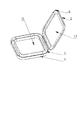
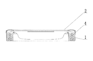
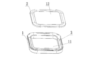
この具体的な実施形態は、図1〜図5に示す、収納本体1と蓋体2とを含むスマートゴミ箱のゴミ袋ユニットを提供する。収納本体1には該収納本体1を貫通する第一開孔11が設けられ、蓋体2には第二開孔12が設けられ、ゴミが第一開孔11と第二開孔12とを通過してゴミ箱内に入るように、第一開孔11と第二開孔12とは互いに対応して設けられる。ここで、第一開孔11および第二開孔12の大きさおよび形状は限定されず、円形であってもよく、方形または他の形状であってもよい。
Example 1
This specific embodiment provides a garbage bag unit of a smart trash can including a storage
収納本体1において、第一開孔11の外側を囲んで、ゴミ袋4を収納するための環状凹溝3が設けられる。ここで、環状凹溝3は開口を有し、開口方向は第一開孔11の方向を向いていてもよく、第一開孔11とは反対の方向を向いていてもよく、第一開孔11の開口方向と一致していてもよい。環状凹溝3の大きさはゴミ袋4の収納量に関わるため、使用する場面や使用密度に合わせて異なる大きさの環状凹溝3を設けることができる。ゴミ袋4の使用量が比較的多い場合には、比較的容量が大きい環状凹溝3を設けることができ、逆の場合には比較的容量の小さい環状凹溝3を設けることができる。
In the
蓋体2は環状凹溝3の開口部を覆う。蓋体2が環状凹溝3の開口部を覆うと、ゴミ袋4は環状凹溝3内に留められ、蓋体2と環状凹溝3の一つの側壁とから形成される環状の間隙であるゴミ袋の出口を介してのみ、ゴミ袋4を引き出すことができる。該間隙の大きさは限定されず、その機能を実現することができる大きさであればよい。
The
使用の際には、環状のゴミ袋4を環状凹溝3の内部に入れ、ゴミ袋4の一端の開口をゴミ袋の出口から引き出して閉じる。このように、ゴミ袋の交換が必要な場合は、ゴミ箱内部の真空装置を起動しさえすれば、真空装置の作用により、ゴミ袋4が強い大気圧を受けてゴミ箱の内部に押し込まれて、ゴミ袋の自動装着が完了する。ゴミ袋4の包装やヒートシールが必要な場合は、自動包装機構を作動させるだけで、プレスバーの作用により、ゴミ袋4が熱溶着装置に押し込まれて、ゴミ袋4の溶断およびヒートシールが行われる。
In use, the
該収納本体1および蓋体2の構造は、ゴミ袋4の移動自由度を制限してゴミ袋4を一方向にしか移動できないようにするだけでなく、ゴミ袋4の形態を固定して、ゴミ袋4を常に広げた状態にしておくこともできるため、ゴミ袋の自動装着プロセスからゴミ袋を広げるステップを省くことができ、ゴミ袋の自動装着および包装機構を大幅に簡略化させ、実現を容易にし、操作を簡便にすることができる。
The structure of the
このような設置により、該ゴミ袋ユニットは、スマートゴミ箱に適用することができ、これによってゴミ袋の全自動での装着および包装機能が容易に実現され、ゴミ箱の自動化およびスマート化のレベルをより一層向上させることができる。また、製造、保管および輸送の過程におけるゴミ袋の破損の発生が効果的に防止される。環状凹溝3の大きさは、ゴミ箱の使用密度や使用する場面に合わせて異なる大きさに設定することができ、コンテナ内のゴミ袋の収容量や包装長さを調節することが容易で、資源を節約することができる。ロール単位でゴミ袋を交換する場合に比べて、ゴミ袋の交換が一段と容易で、効率の向上に利する。ゴミ袋ユニットは一体型構造であり、組み立てが容易で、製造および設置コストの低減に利する。
With such an installation, the garbage bag unit can be applied to a smart garbage bin, whereby a fully automatic loading and packaging function of the garbage bag is easily realized, and the level of automation and smartization of the garbage bin is improved. It can be further improved. Further, the occurrence of breakage of the garbage bag during the manufacturing, storage and transportation processes is effectively prevented. The size of the
なお、環状凹溝3の開口部を覆う蓋体2の固定方式は、蓋体2が収納本体1と直接連結され、前記蓋体2が一つの側辺を介して前記収納本体1と回動可能に連結されて一体型構造を形成する方式であってもよい。このようにして、本ゴミ袋ユニットの安定性および信頼性を保証することができる。図12に示すように、蓋体2と収納本体1とが取り外し可能に連結されてもよい。こうすることにより、ゴミ袋を取り付ける際に、蓋体2を完全に取り外すことができ、ゴミ袋の装着が容易となる。当然ながら、他の固定方式としてもよい。
In addition, the fixing method of the
本ゴミ袋ユニットは、収納本体1に適合し、かつ、収納本体1の環状凹溝3内に装入することができるゴミ袋4をさらに含む。ここで、ゴミ袋4は、内部全体が貫通された筒状構造を呈しており、両端がともに開口を有する形式でもよく、一端に開口を有して他端は閉じた形式でもよい。また、該ゴミ袋4は、折り畳まれて環状をなすように、その軸方向に沿って蛇腹状に折ることができ、その環状の大きさは、環状凹溝3の内部に装入できるように、環状凹溝3の大きさと一致させる。該ゴミ袋4は一体型の、ミシン目が入っていないタイプであるため、ゴミ袋4の長さは限定されず、使用の際に、相応の長さに切って折り畳み、環状凹溝3内に装入することができる。
The garbage bag unit further includes a
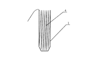
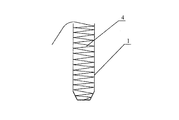
なお、ゴミ袋4を蛇腹状に折り畳む方式は図4および5に示す方式であり、折り畳み方向は環状凹溝3の側壁に垂直であってもよく、環状凹溝3の側壁に平行であってもよく、また、具体的な状況に応じて、それ以外の方向であってもよい。
The method of folding the
ゴミ袋4を使用する際、必要に応じて一定の長さおよび直径を有するゴミ袋4を切り出すことができる。手作業で、または一定の工具によって、ミシン目が入っていない一体型筒状ゴミ袋をその軸方向に沿って環状に折り畳み、折り畳まれた環状のゴミ袋4を収納本体1の環状凹溝3内に配置することで、ゴミ袋4の装入が完了する。さらに、ゴミ袋が装入されたゴミ袋ユニットをゴミ箱の対応する位置の対応する構造内に置くことで、このミシン目が入っていない一体型筒状ゴミ袋を使用することができる。当然ながら、環状凹溝3内に押し込まれたゴミ袋4の一端を引き出してシールしてもよい。ここで、シール方式はヒートシールであってもよいが、ヒートシールに限らず、一つ目のゴミ袋の自動使用が容易なその他のシール方式であってもよく、シールを行わず、手作業で一定の距離だけ下げて、自動包装機構に自動包装およびシールを行わせてもよい。
When the
このような設置により、従来のゴミ袋に比べて、該ゴミ袋ユニットは基本的に制限されず、より多くのゴミを封入することができる。また、ゴミの量に応じて主体的に包装位置を選択することが可能で、残りの長さのゴミ袋を続けて使用することができるため、ゴミ袋の容量を十分に利用して、ゴミ袋という資源の浪費を防止することができ、自動包装および自動ゴミ袋交換の実現が容易となり、従来のスマートゴミ箱の自動化およびスマート化のレベルを向上させることができる。 By such an installation, the garbage bag unit is basically not restricted as compared with the conventional garbage bag, and more garbage can be enclosed. In addition, the packaging position can be independently selected according to the amount of garbage, and the remaining length of garbage bags can be used continuously. Waste of the resources of bags can be prevented, automatic packaging and automatic garbage bag exchange can be easily realized, and the level of automation and smartness of conventional smart trash cans can be improved.
本実施例において、図3に示すように、ゴミ袋の出口を囲む環状凹溝3の一つの側壁縁に折り返し縁構造5が設けられ、かつ、該折り返し縁構造5は環状凹溝3の外側に向かって折り返される。これにより、該折り返し縁構造5は、ゴミ袋4をゴミ袋出口から引き出す際に、ゴミ袋4へのガイド機能を果たすだけでなく、引っかきによるゴミ袋4の損傷を防止して、資源の浪費を減少させることができる。
In this embodiment, as shown in FIG. 3, a folded
一部の実施例において、環状凹溝3の開口方向と第一開孔11の開口方向とは一致している。この場合、環状凹溝3を囲む二つの側壁は内壁と外壁であり、内壁は第一開孔11に近い一側に位置しており、第一開孔11と環状凹溝3の内部空間とを仕切ることができ、外壁は第一開孔11から離れた一側に位置しており、環状凹溝3と外部空間とを仕切ることができる。これにより、環状凹溝3の開口と内部空間の周方向の長さはほぼ一致するため、ゴミ袋4の装入が容易になり、さらに、環状凹溝3と蓋体2の連結がより安定し、ゴミ袋ユニットの一体化のレベルの向上に利する。
In some embodiments, the opening direction of the
蓋体2は第二開孔12を有する構造であるため、蓋体2は第二開孔12に近い内縁と第二開孔12から離れた外縁を有する。ここで、蓋体2の内縁と環状凹溝3の内壁との間にはゴミ袋の出口を形成する間隙が存在し、蓋体2の外縁と環状凹溝3の外壁が互いに連結される。これにより、ゴミ袋4の一端をゴミ袋の出口の間隙部から引き出して閉じることができる。ゴミ袋を装着する際に、外気が第二開孔12および第一開孔11を介してゴミ袋4をゴミ箱内に押し込む。このとき、ゴミ袋4をゴミ袋の出口部分から順に引き出すことができる。これにより、ゴミ袋資源の浪費を減少させることができ、さらに、ゴミ袋を常に広げた状態にしておくことができるため、ゴミ袋の装着プロセスにおいてゴミ袋を広げるステップを省くことができ、ゴミ袋の全自動での装着および包装機能の実現を容易にし、ゴミ箱の自動化およびスマート化のレベルをより一層向上させる。
Since the
当然ながら、他の実施例において、蓋体2の内縁を環状凹溝3の内壁と連結させ、蓋体2の外縁と環状凹溝3の外壁との間に間隙を設けて、ゴミ袋の出口を形成してもよい。得られる有益な効果は前述の効果とほぼ一致するため、説明を省略する。
Of course, in another embodiment, the inner edge of the
蓋体2の外縁の一つの側辺は環状凹溝3の外壁と回動可能に連結される。ここで、回動可能な連結とは、回転軸を介した連結であってもよく、折目を利用した連結固定であってもよく、当然ながらその他の回動可能な連結形式であってもよい。これにより、ゴミ袋4を環状凹溝3内に入れようとするときに、蓋体2を回動させれば環状凹溝3の開口を開放することができ、ゴミ袋4を環状凹溝3内に留めようとするときに、蓋体2を回動させれば環状凹溝3の開口部を覆うことができるため、構造が簡易で実現が容易であり、構造の安定性の向上に利する。
One side of the outer edge of the
さらに、蓋体2の外縁に折り曲げ構造6が設けられる。該折り曲げ構造6は環状凹溝3の外壁の方向を向いており、また、折り曲げ構造6は外壁と締まり嵌めされる。これにより、蓋体2がこの締まり嵌め構造によって環状凹溝3の開口部に堅固に取り付けられ、構造の安定性を向上させることができる。当然ながら、折り曲げ構造6と外壁はバックル構造によって互いに係合されてもよく、それにより、ゴミ袋ユニットの一体化のレベルをより一層向上させ、ゴミ袋ユニットの着脱を容易にすることができる。
Further, a
ここで、バックル構造は、互いに係合する係止溝と係止ブロックとを含んでもよい。係止溝と係止ブロックの一方は折り曲げ構造6の内側に設置され、他方は環状凹溝3の外壁に設置される。折り曲げ構造6が環状凹溝3の外壁の近傍に位置するとき、係止ブロックは係止溝の内部に嵌合されて、係止を実現することができる。このような設置により、バックル構造の実現が容易になり、操作は簡便となり、蓋体2と収納本体1との連結安定性が向上する。
Here, the buckle structure may include a locking groove and a locking block that engage with each other. One of the locking groove and the locking block is installed inside the
一部の実施例において、収納本体1と蓋体2の全体形状は、各々の角が面取りされた方形環状構造とされる。ゴミ箱の多くは方形であるため、このような設置により、方形のゴミ箱への応用をより容易にすることができ、また、ゴミ箱との連結をより堅固にすることができるため、ゴミ袋ユニットがゴミ箱内で回転して移動することを効果的に防止することができる。該ゴミ袋ユニットの形状は方形環状に限らず、円形環状であってもよいし、その他の形状であってもよい。
In some embodiments, the overall shape of the
収納本体1および蓋体2の構造はプラスチック材料で成形されてもよく、段ボールを折り畳んで接着成形されてもよく、または、金属を折り畳んで曲げて成形されてもよい。これにより、材料の入手および加工が容易になり、様々な場面における要求に応じることができる。当然ながら、具体的な状況に応じて、その他の材料であってもよい。
The structures of the storage
前述の実施例およびその好適な態様の内容を総合して、本ゴミ袋ユニットについて具体的に説明する。 The garbage bag unit will be specifically described based on the contents of the above-described embodiment and preferred embodiments thereof.
本願は、中央部に開孔を含むコンテナ式構造(すなわち、ゴミ袋コンテナ)を採用し、ゴミが必ず中央部の開孔を通過してゴミ袋4の中に落ちるゴミ袋ユニットを提供する。該コンテナ式構造は、形式上、蓋体2と収納本体1とに分けることができ、収納本体1にはゴミ袋4を装入するための環状凹溝3が設けられ、蓋体2は環状凹溝3の開口部を覆い、かつ、収納本体1と一体に連結される。ここで、該蓋体2および収納本体1の形状は方形でも円形でもよく、具体的にこの構造を使用するゴミ箱の形状に応じて変更することができる。該コンテナ式構造(すなわち、ゴミ袋コンテナ)は、一つの部品のみからなる一体型構造の態様でもよく、前記蓋体2が一つの側辺を介して前記収納本体1と回動可能に連結されて一体型構造を形成してもよく、蓋体2と収納本体1とを二つの部品に分離して組み立てて使用してもよい。該蓋体2は、テープ、金属ワイヤまたはその他の組み合わせでゴミ袋4を該収納本体1内に保持するように設置されてもよい。該蓋体2および収納本体1はプラスチック材料で成形されてもよく、段ボールを折り畳んで接着成形されてもよく、または、金属を折り畳んで曲げて成形されてもよい。該収納本体1の環状凹溝3の内壁には環状の樋(すなわち、折り返し縁構造)が設けられるが、環状の樋の位置は環状凹溝3の内壁に限定されず、外壁またはその他の位置に分布してもよい。
The present application provides a trash bag unit that employs a container-type structure (that is, a garbage bag container) including an opening in the center and that always passes through the opening in the center and falls into the
さらに、ミシン目が入っていない一体型の筒状ゴミ袋4を含む。ゴミ袋4の一端は、新しいゴミ袋4に交換した後で最初に使用する際の自動取り出しを容易にするために、シールされてもよいし、両端がいずれもシールされなくてもよい。使用のために装入するときは、手作業で、または機械によって、ゴミ袋4をその軸方向に沿って蛇腹状に折り畳んで環状にし、収納本体1内に入れる。ここで、収納本体1は、一般的には開孔を有するコンテナ式構造であるが、コンテナ式構造に限定されず、溝状構造、環状構造および相応の固定ラック構造であってもよい。通常の使用の際には、該ゴミ袋4は一般的にゴミ箱の内部の上部位置に収納されるが、ゴミ箱の内部の任意の位置に収納されてもよい。特に、環状に折り畳まれた該ゴミ袋4は、一般的にはゴミ箱の入口と平行になるように配置される。
Further, it includes an integral
該ゴミ袋ユニットの組み立てステップには、
手作業で、または一定の工具によって、ミシン目が入っていない筒状ゴミ袋4を軸方向に沿って折り畳んで環状にし、ゴミ袋4の長さおよび直径は、使用要件によりカスタマイズされるステップと、
折り畳まれた環状のゴミ袋4を前記環状凹溝3の内部に形成されたゴミ袋4の収納領域に押し込むステップと、
環状凹溝3内に押し込まれた筒状のゴミ袋4の一端を引き出してシールするステップであって、シール方式はヒートシール方式であり、ただし、ヒートシールによるシールに限定されず、一つ目のゴミ袋4の自動取り出しが容易なその他のシール方式を用いてもよいステップと、
蓋体2を回動させて収納本体1の環状凹溝3の開口部を覆うステップと、が含まれる。蓋体2には折り曲げ構造6が設けられているため、蓋体2と収納本体1とを迅速に結合させることができる。このようにして該ゴミ袋ユニットの組み立て作業を完了する。
The steps of assembling the garbage bag unit include:
Manually or by means of a tool, the unperforated
Pushing the folded
This is a step of pulling out one end of the
Turning the
本願はさらに、前述の実施例に記載のゴミ袋ユニットを含むスマートゴミ箱を提供する。このようなスマートゴミ箱は、ゴミ袋の全自動での装着および包装機能を容易に実現することができ、ゴミ箱の自動化およびスマート化のレベルをより一層向上させる。また、製造、保管および輸送の過程におけるゴミ袋4の破損の発生が効果的に防止される。環状凹溝3の大きさは、ゴミ箱の使用密度および使用する場面に合わせて異なる大きさに設定することができ、コンテナ内のゴミ袋4の収容量や包装長さの調整が容易で、資源を節約することができる。ロール単位でゴミ袋を交換する場合に比べて、ゴミ袋の交換がより容易で、効率の向上に利する。ゴミ袋ユニットは一体型構造であり、組み立てが容易で、製造および設置コストの低減に利する。この有益な効果は、前述のゴミ袋ユニットとほぼ類似するため、説明を省略する。
The present application further provides a smart trash can including the trash bag unit described in the previous embodiment. Such a smart trash can can easily realize a fully automatic loading and packaging function of the trash bag, and further improves the level of automation and smartness of the trash can. Further, the occurrence of breakage of the
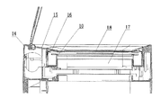
好ましくは、図13に示すように、前記収納本体1と前記スマートゴミ箱の筒体とは一体型構造である。すなわち前記収納本体1とゴミ箱本体14とが一体成形され、プレスカバー16がゴミ袋ユニットの蓋体となる。
Preferably, as shown in FIG. 13, the storage
実施例2
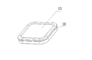
図6〜11に示すように、本スマートゴミ箱は、ゴミ袋ユニット位置決め機構をさらに含む。ここで、ゴミ袋ユニット10はゴミ袋コンテナおよびゴミ袋コンテナ内に装入されたゴミ袋4(図4および図5を参照)を含み、ゴミ袋コンテナは、ゴミ箱本体14内に設置される。ゴミ箱内へのゴミの投入に影響しないように、ゴミ袋コンテナにはゴミを通過させる第三開孔13が設けられる。ゴミ箱本体14内には、ゴミ袋コンテナを支持する収納ラック15がさらに設置されるとともに、ゴミ箱本体14へのゴミの投入を円滑にするために、収納ラック15には、第三開孔13に対応する第四開孔17が設けられている。ゴミ袋コンテナの交換を容易にするために、ゴミ箱本体14には、ゴミ袋コンテナの出し入れに供する通路がさらに設けられている。
Example 2
As shown in FIGS. 6 to 11, the smart trash can further includes a trash bag unit positioning mechanism. Here, the
当業者であれば、前記ゴミ袋ユニット10がゴミ袋コンテナのみを含む構成であってもよいことを容易に理解するであろう。前記ゴミ袋4を前記ゴミ袋コンテナと一緒に組み立てて販売する必要はなく、ユーザはゴミ袋4を別途購入して、使用時にゴミ袋コンテナ内に取り付けてもよい。
Those skilled in the art will readily understand that the
さらに、通路はゴミ箱本体14の頂部または側部に設けられてもよい。通路がゴミ箱本体14の頂部に設けられた場合には、ゴミ箱本体14の高さ方向に沿って使い終わったゴミ袋コンテナを取り出し、それから新しいゴミ袋コンテナを反対方向に沿って収納ラック15に入れればよい。通路がゴミ箱本体14の側部に設けられた場合には、ゴミ箱の一側から収納ラック15を引き出して、使い終わったゴミ袋コンテナを取り出し、それから新しいゴミ袋コンテナを収納ラック15に入れて、反対方向に沿ってゴミ箱本体14内に押し込めばよい。これにより、ゴミ袋コンテナの取り出しが容易になるだけでなく、ゴミ箱内のスペースを大幅に節約することもできる。当然ながら、実際の具体的な状況に応じて、通路をその他の位置に設けてもよい。
Further, the passage may be provided on the top or side of the
従来技術においては、ゴミ袋を使い切ると、ゴミ箱本体14内からゴミ袋収納ラックを取り外して、新しいゴミ袋をゴミ袋収納ラックの収納スペースに入れた後、再びゴミ袋収納ラックをゴミ箱本体内に取り付けていたが、着脱が面倒であり、時間と労力を要していた。前述の設置によれば、ゴミ袋を使い切ったときに、ゴミ袋コンテナを取り出して、ゴミ袋が装入されている新しいゴミ袋コンテナを入れるだけでよいため、ゴミ袋収納ラックを着脱する必要がなく、交換が容易であり、上記の課題が解決される。
In the related art, when the garbage bag is used up, the trash bag storage rack is removed from the trash box
本実施例の好適な態様において、収納ラック15とゴミ箱本体14とは一体型構造とされてもよく、実際の具体的な状況に応じて、分離型構造とされてもよい。
In a preferred embodiment of the present embodiment, the
第一の好適な態様において、図7に示すように、収納ラック15とゴミ箱本体14とは一体型構造とされる。好ましくは、このときの通路はゴミ箱本体14の頂部に設けられ、収納ラック15は環状凹溝構造とされ、ゴミ袋コンテナを装入するための凹溝構造は、ゴミ箱本体14の内周方向を囲むように設けられる。好ましくは、収納ラック15はゴミ箱本体14の内壁の頂部に設置される。このようにして、ゴミ箱内のスペースを節約することができ、袋のスムーズな引き出しが保証される。
In the first preferred embodiment, as shown in FIG. 7, the
ゴミ袋コンテナを固定するために、位置決め機構はゴミ袋コンテナ固定用のプレスカバー16をさらに含む。プレスカバー16はゴミ袋コンテナの上方に押し付けられ、かつ、プレスカバー16には第三開孔13および第四開孔17に対応する第五開孔18が設けられる。すなわち、プレスカバー16の断面形状は、ゴミ袋コンテナ11の断面形状と同じであり、かつ、プレスカバー16とゴミ箱本体14とは取り外し可能に連結される。
In order to fix the trash bag container, the positioning mechanism further includes a
さらに、本実施例において、プレスカバー16とゴミ箱本体14との間には吸着装置が設けられる。具体的には、吸着装置は強磁気吸着構造であってもよい。
Further, in the present embodiment, a suction device is provided between the
前記強磁気吸着構造は、プレスカバー16上に設けられた第一磁石と、ゴミ箱本体内に設けられた第二磁石とを含み、第一磁石の磁力と第二磁石の磁力とが吸引し合って、プレスカバー16をゴミ袋コンテナの上方に押し付ける。
The strong magnetic attraction structure includes a first magnet provided on the
当業者であれば、前記強磁気吸着構造が一つの磁石と一つの鉄ブロックからなる構造であってもよく、両者が吸引し合うことによってプレスカバーをゴミ袋コンテナの上方に押し付け、前記磁石と鉄ブロックのうちの一方をプレスカバー16上に設け、他方をゴミ箱本体14内に設けてもよいことを容易に理解するであろう。
If a person skilled in the art, the strong magnetic attracting structure may be a structure including one magnet and one iron block, and the two attract each other to press the press cover above the garbage bag container, and the magnet and the magnet are attached. It will be readily understood that one of the iron blocks may be provided on the
本実施例において、ゴミ袋コンテナを交換するステップは、以下の通りである。 In this embodiment, the steps of replacing the trash bag container are as follows.
まずゴミ箱の回動蓋を開ける。それからプレスカバー16を取り外す。ゴミ箱の高さ方向に沿って、使い終わったゴミ袋コンテナを取り出す。新しいゴミ袋コンテナを反対方向に沿って収納ラック15に入れる。最後に、プレスカバー16を被せると、ゴミ袋コンテナの交換が完了し、続けてゴミ箱を使用することができる。
First, open the rotating lid of the trash can. Then, the
第二の好適な態様においては、図8に示すように、収納ラック15とゴミ箱本体14とは分離型構造とされる。好ましくは、このときの通路はゴミ箱本体14の側部に設けられ、収納ラック15とゴミ箱本体14との間にイジェクト機構または電動イジェクト機構が設けられ、収納ラック15は、イジェクト機構の作用で通路に排出されるか、または、通路内に係止される。例えば、電動イジェクト機構は、モータと、モータに接続された伝動装置とを含み、モータは、伝動装置を介して収納ラック15を押し出すことができる。電動イジェクト機構は、従来技術におけるコンピュータの光学ドライブのイジェクト機構に類似したものであってもよい。
In the second preferred embodiment, as shown in FIG. 8, the
なお、図9および図10に示すように、従来技術におけるメモリカードのイジェクト機構を参照して、本実施例におけるイジェクト機構は、具体的にはスライドレール201、イジェクト装置202およびバネ203を含む。スライドレール201は、ロック部材208、係合位置206および押し出し位置207を有する。イジェクト装置202は、スライドレール201上に取り付けられ、係合位置206と押し出し位置207との間を摺動して、収納ラック15を排出することができる。バネ203は、スライドレール201とスタッド204との間を連結して、排出を行う弾発力を提供する。イジェクト装置202をスライドレール201の押し出し位置207から係合位置206まで押し込むと、イジェクト装置202がロック部材208に引っ掛かり、かつ、これによりバネ203が伸びて弾発力が生じ、このとき、収納ラック15は通路内部に押し込まれて係止される。イジェクト装置202が再び押されると、イジェクト装置202はロック部材208から解放されて、摺動しながら押し出し位置207に戻り、排出を行う弾発力によって収納ラック15を排出する。
As shown in FIGS. 9 and 10, the ejection mechanism in the present embodiment specifically includes a
当然ながら、他の実施例において、ゴミ箱本体14の側部から手作業でゴミ袋コンテナを引き出してもよいし、または、その他の方式で引き出してもよいが、ここでは詳細な説明を省略し、実際の具体的な状況に応じて決定する。
Of course, in another embodiment, the trash bag container may be manually pulled out from the side of the trash box
具体的には、図11に示すように、本実施例におけるスマートゴミ箱の作業原理は、以下の通りである。まず、電力入力線23を介して電池をフル充電し、スマートゴミ箱を適切な位置に置く。ユーザが近づいてスマートゴミ箱にゴミを捨てようとすると、スマートゴミ箱上の赤外線センサモジュールによって感知され、回動蓋20が自動で開く。ユーザが立ち去ると、回動蓋20は自動で閉じる。スマートゴミ箱の中身が一杯になり、ゴミ袋を包装する必要が生じたときは、パネル21のシール/袋交換ボタンを押すだけで、スマートゴミ箱内のチップ(例えば、マイクロ・コントローラ・ユニット)が、スマートゴミ箱が包装プロセスを実行するように制御を行う。内筒モジュール22を外側に45度傾けて内筒モジュール22の口部を露出させると、ユーザはゴミで一杯になったゴミ袋を捨てることができる。その後、電池および回路基板のシングルチップマルチプロセッサは、内筒モジュール22に密閉空間が形成されるように、スマートゴミ箱の開放構造を閉じる。スマートゴミ箱内のチップ(例えば、マイクロ・コントローラ・ユニット)は、スマートゴミ箱が袋の交換プロセスを実行するように制御を行い、プロセスの実行が完了すると、ユーザはまたゴミ箱にゴミを捨てることができるようになる。
Specifically, as shown in FIG. 11, the working principle of the smart trash can in the present embodiment is as follows. First, the battery is fully charged via the
なお、本明細書に記載の「第一」、「第二」、「第三」、「第四」、「第五」などの語は、具体的な順序を限定するものではなく、単に各部品または機能を区別するためのものである。 Note that terms such as “first”, “second”, “third”, “fourth”, and “fifth” described in the present specification do not limit the specific order, and simply refer to It is for distinguishing parts or functions.
以上の説明は、本発明の具体的な実施形態にすぎず、本発明の保護範囲はこれに限定されるものではい。当業者であれば、本発明に開示された技術範囲において、変更または代替に容易に想到することができ、これらはすべて本発明の保護範囲内に含まれる。したがって、本発明の保護範囲は、「特許請求の範囲」の記載に基づいて定められるべきである。 The above description is only specific embodiments of the present invention, and the protection scope of the present invention is not limited to these embodiments. Those skilled in the art can easily conceive of modifications or alternatives in the technical scope disclosed in the present invention, and all of these are included in the protection scope of the present invention. Therefore, the protection scope of the present invention should be determined based on the description in the claims.
1 収納本体
2 蓋体
3 環状凹溝
4 ゴミ袋
5 折り返し縁構造
6 折り曲げ構造
10 ゴミ袋ユニット
11 第一開孔
12 第二開孔
13 第三開孔
14 ゴミ箱本体
15 収納ラック
16 プレスカバー
17 第四開孔
18 第五開孔
20 回動蓋
21 パネル
22 内筒モジュール
23 電力入力線
201 スライドレール
202 イジェクト装置
203 バネ
204 スタッド
206 係合位置
207 押し出し位置
208 ロック部材
REFERENCE SIGNS
Claims (15)
ゴミを通過させる第一開孔(11)と、前記第一開孔(11)の外側を囲み、ゴミ袋(4)の収納に用いる環状凹溝(3)とが設けられた収納本体(1)、および
前記第一開孔(11)に対応する第二開孔(12)が設けられ、前記環状凹溝(3)の開口部を覆い、前記環状凹溝(3)の一つの側壁との間に間隙が設けられてゴミ袋の出口を形成する蓋体(2)
を含むことを特徴とするゴミ袋ユニット。 A trash bag unit for a smart trash can,
A storage body (1) provided with a first opening (11) through which dust passes, and an annular groove (3) surrounding the outside of the first opening (11) and used to store a trash bag (4). ), And a second opening (12) corresponding to the first opening (11) is provided to cover the opening of the annular groove (3), and one side wall of the annular groove (3). (2) having a gap between them to form an outlet for the garbage bag
A garbage bag unit comprising:
前記蓋体(2)の内縁と前記内壁との間に前記間隙が形成され、前記蓋体(2)の外縁は前記外壁と連結されることを特徴とする請求項1に記載のゴミ袋ユニット。 The opening direction of the annular groove (3) matches the opening direction of the first opening (11), and the inner wall of the annular groove (3) is closer to the first opening (11). An outer wall of the annular groove (3) is a side wall farther from the first opening (11);
The trash bag unit according to claim 1, wherein the gap is formed between an inner edge of the lid (2) and the inner wall, and an outer edge of the lid (2) is connected to the outer wall. .
ゴミ袋ユニット位置決め機構をさらに含み、前記ゴミ袋ユニット位置決め機構は、ゴミ箱本体(14)内に設置された、前記ゴミ袋コンテナを支持する収納ラック(15)を含み、かつ、前記収納ラック(15)には前記第三開孔(13)に対応する第四開孔(17)が設けられ、前記ゴミ箱本体(14)には前記ゴミ袋コンテナの出し入れに供する通路が設けられることを特徴とする請求項9に記載のスマートゴミ箱。 The trash bag unit (10) is a smart trash box including a trash bag container, wherein the trash bag container is provided with a third opening (13) through which trash passes.
A trash bag unit positioning mechanism, wherein the trash bag unit positioning mechanism includes a storage rack (15) installed in the trash box main body (14) and supporting the trash bag container, and the storage rack (15); ) Is provided with a fourth opening (17) corresponding to the third opening (13), and the trash box main body (14) is provided with a passage for taking in and out the trash bag container. The smart trash can according to claim 9.
前記強磁気吸着構造は、前記プレスカバー(16)上に設けられた第一磁石と、前記ゴミ箱本体(14)内に設けられた第二磁石とを含み、前記第一磁石の磁力と前記第二磁石の磁力とが吸引し合って前記プレスカバー(16)を前記ゴミ袋コンテナの上方に押し付けるか、または、
前記強磁気吸着構造は、一つの磁石と一つの鉄ブロックとが吸引し合って前記プレスカバー(16)をゴミ袋コンテナの上方に押し付けるものであり、前記磁石と鉄ブロックのうちの一方は前記プレスカバー(16)上に設けられ、他方は前記ゴミ箱本体(14)内に設けられる
ことを特徴とする請求項14に記載のスマートゴミ箱。 The adsorption device has a strong magnetic adsorption structure,
The strong magnetic attraction structure includes a first magnet provided on the press cover (16) and a second magnet provided in the trash box main body (14), and a magnetic force of the first magnet and the second magnet are provided. The magnetic force of the two magnets attracts and presses the press cover (16) above the garbage bag container, or
In the strong magnetic attraction structure, one magnet and one iron block attract each other and press the press cover (16) above a trash bag container, and one of the magnet and the iron block is The smart trash bin according to claim 14, characterized in that it is provided on a press cover (16) and the other is provided in the trash bin body (14).
Applications Claiming Priority (2)
| Application Number | Priority Date | Filing Date | Title |
|---|---|---|---|
| CN201810711673.6 | 2018-07-03 | ||
| CN201810711673.6A CN108974704A (en) | 2018-07-03 | 2018-07-03 | Garbage bag components and smart trash cans |
Publications (1)
| Publication Number | Publication Date |
|---|---|
| JP2020007152A true JP2020007152A (en) | 2020-01-16 |
Family
ID=64539841
Family Applications (1)
| Application Number | Title | Priority Date | Filing Date |
|---|---|---|---|
| JP2019088287A Pending JP2020007152A (en) | 2018-07-03 | 2019-05-08 | Garbage bag unit, garbage bag positioning mechanism and smart garbage bin |
Country Status (3)
| Country | Link |
|---|---|
| EP (1) | EP3590869B1 (en) |
| JP (1) | JP2020007152A (en) |
| CN (2) | CN115583449A (en) |
Families Citing this family (8)
| Publication number | Priority date | Publication date | Assignee | Title |
|---|---|---|---|---|
| CN115583449A (en) * | 2018-07-03 | 2023-01-10 | 上海拓牛智能科技有限公司 | Garbage bag assembly and assembly method thereof, intelligent trash can, and garbage bag laying method |
| CN109625700A (en) * | 2018-12-29 | 2019-04-16 | 上海拓牛智能科技有限公司 | A kind of automatic packaging changes a bag intelligent garbage bin |
| CN109498167B (en) * | 2019-01-22 | 2024-06-21 | 福建宸润生物科技有限公司 | Disposable medical protective sleeve and manufacturing method thereof |
| CN111977219B (en) * | 2019-05-22 | 2023-05-23 | 上海拓牛智能科技有限公司 | Garbage bin is supported to no staving two |
| GB2600912B (en) * | 2020-09-28 | 2023-04-26 | Sangenic International Ltd | Waste storage refill |
| EP3984916A1 (en) * | 2020-10-19 | 2022-04-20 | Venture Alliance Limited | A device for waste disposal |
| CN112978135B (en) * | 2021-02-08 | 2024-08-13 | 哈尔滨工业大学 | Household integrated intelligent waste disposal bin |
| CN114190805A (en) * | 2021-12-06 | 2022-03-18 | 合肥工业大学 | A packing mechanism and a special toilet for a nursing bed |
Citations (9)
| Publication number | Priority date | Publication date | Assignee | Title |
|---|---|---|---|---|
| JPH0286565A (en) * | 1988-08-02 | 1990-03-27 | Process Improvements Ltd | Cassette receiving flexible pipe possible to deliver |
| JPH03179232A (en) * | 1989-12-06 | 1991-08-05 | Koji Tsuhara | Cassette with lid for preparing tissue sample |
| WO1995009777A1 (en) * | 1993-10-01 | 1995-04-13 | Hiroshi Yoshihara | Cover opening mechanism |
| JP2005255212A (en) * | 2004-03-11 | 2005-09-22 | Kotobuki Seihan Printing Co Ltd | Premium storage container |
| JP2010525995A (en) * | 2007-05-04 | 2010-07-29 | プレイテックス プロダクツ エルエルシー | Container that can take out flexible tubing |
| US20120211494A1 (en) * | 2011-02-18 | 2012-08-23 | Michel Morand | Waste-disposal system for film-dispensing units |
| JP2014201347A (en) * | 2013-04-08 | 2014-10-27 | 株式会社ホタルコーポレーション | Lunch container |
| CN204617330U (en) * | 2015-04-21 | 2015-09-09 | 宁波兰花电器制造有限公司 | Electric heating mess tin |
| CN206013572U (en) * | 2016-08-24 | 2017-03-15 | 上海拓牛实业有限公司 | Without breakpoint refuse bag apparatus for automatic change |
Family Cites Families (13)
| Publication number | Priority date | Publication date | Assignee | Title |
|---|---|---|---|---|
| JP3774429B2 (en) * | 2002-11-27 | 2006-05-17 | 株式会社グリーンライフ | Waste treatment equipment |
| CN2756590Y (en) * | 2004-12-09 | 2006-02-08 | 王丽春 | Garbage can with garbage bag adsorption function |
| US7992742B1 (en) * | 2007-05-16 | 2011-08-09 | Sinclair Worldwide, Inc. | Refuse receptacle with spring bias arrangement |
| WO2013005236A1 (en) * | 2011-07-05 | 2013-01-10 | Bellia Nichol | Method for storing organic waste and refuse container therefor |
| CN202670550U (en) * | 2012-02-28 | 2013-01-16 | 深圳市凡人再生资源有限公司 | Dustbin capable supplying bags continuously and matched used serial connection garbage bag |
| USD695541S1 (en) * | 2012-10-24 | 2013-12-17 | Munchkin, Inc. | Cassette |
| US9745127B1 (en) * | 2013-09-23 | 2017-08-29 | David M Stravitz | Waste containers with unitary insert |
| CN206125974U (en) * | 2016-08-24 | 2017-04-26 | 上海拓牛实业有限公司 | Novel disposal bag subassembly |
| CN207226181U (en) * | 2017-09-25 | 2018-04-13 | 上海拓牛实业有限公司 | Intelligent garbage bin |
| CN107934278A (en) * | 2017-12-05 | 2018-04-20 | 陈政 | Lower-discharging type intelligent garbage bin |
| CN208453666U (en) * | 2018-07-03 | 2019-02-01 | 上海拓牛智能科技有限公司 | Garbage bag component positioning structure and intelligent trash can |
| CN115583449A (en) * | 2018-07-03 | 2023-01-10 | 上海拓牛智能科技有限公司 | Garbage bag assembly and assembly method thereof, intelligent trash can, and garbage bag laying method |
| CN208531321U (en) * | 2018-07-03 | 2019-02-22 | 上海拓牛智能科技有限公司 | Rubbish bag assembly and intelligent garbage bin |
-
2018
- 2018-07-03 CN CN202211145494.3A patent/CN115583449A/en active Pending
- 2018-07-03 CN CN201810711673.6A patent/CN108974704A/en active Pending
-
2019
- 2019-03-13 EP EP19162665.4A patent/EP3590869B1/en active Active
- 2019-05-08 JP JP2019088287A patent/JP2020007152A/en active Pending
Patent Citations (9)
| Publication number | Priority date | Publication date | Assignee | Title |
|---|---|---|---|---|
| JPH0286565A (en) * | 1988-08-02 | 1990-03-27 | Process Improvements Ltd | Cassette receiving flexible pipe possible to deliver |
| JPH03179232A (en) * | 1989-12-06 | 1991-08-05 | Koji Tsuhara | Cassette with lid for preparing tissue sample |
| WO1995009777A1 (en) * | 1993-10-01 | 1995-04-13 | Hiroshi Yoshihara | Cover opening mechanism |
| JP2005255212A (en) * | 2004-03-11 | 2005-09-22 | Kotobuki Seihan Printing Co Ltd | Premium storage container |
| JP2010525995A (en) * | 2007-05-04 | 2010-07-29 | プレイテックス プロダクツ エルエルシー | Container that can take out flexible tubing |
| US20120211494A1 (en) * | 2011-02-18 | 2012-08-23 | Michel Morand | Waste-disposal system for film-dispensing units |
| JP2014201347A (en) * | 2013-04-08 | 2014-10-27 | 株式会社ホタルコーポレーション | Lunch container |
| CN204617330U (en) * | 2015-04-21 | 2015-09-09 | 宁波兰花电器制造有限公司 | Electric heating mess tin |
| CN206013572U (en) * | 2016-08-24 | 2017-03-15 | 上海拓牛实业有限公司 | Without breakpoint refuse bag apparatus for automatic change |
Also Published As
| Publication number | Publication date |
|---|---|
| CN108974704A (en) | 2018-12-11 |
| EP3590869C0 (en) | 2023-06-28 |
| EP3590869B1 (en) | 2023-06-28 |
| CN115583449A (en) | 2023-01-10 |
| EP3590869A1 (en) | 2020-01-08 |
Similar Documents
| Publication | Publication Date | Title |
|---|---|---|
| EP3590869B1 (en) | Trash bag assembly for smart trash receptacle, trash bag assembly locator and smart trash receptacle | |
| US20240190646A1 (en) | Film-dispensing cassette and rimmed bag for waste-disposal unit | |
| JP6166657B2 (en) | Folding film cassette and toilet system using this cassette | |
| CN208531321U (en) | Rubbish bag assembly and intelligent garbage bin | |
| KR200449987Y1 (en) | Garbage box | |
| CN108974703B (en) | Garbage bag component positioning structure and smart trash can | |
| KR200441166Y1 (en) | Newspaper Waste Bin | |
| JP3994407B2 (en) | Waste storage container | |
| CN222454041U (en) | Film placing box | |
| JP2003020170A (en) | Container for welding wire | |
| JPH07285584A (en) | Vacuum-packaged tissue paper | |
| TWI265133B (en) | Multifunctional pack box | |
| JPS594949Y2 (en) | packaging box | |
| JP3111647U (en) | Tissue paper storage box, storage box complex, and tissue paper storage box storage body | |
| JP6768558B2 (en) | Portable hygiene tissue paper storage container and portable hygiene tissue paper storage container unit | |
| JP4065013B1 (en) | Clothing storage | |
| JPS63147702A (en) | Container | |
| JP3030043U (en) | Fluorescent lamp packaging | |
| KR200388288Y1 (en) | Recycling trash can | |
| KR200267950Y1 (en) | packing box | |
| KR960005298Y1 (en) | Shapping case | |
| JPS582788Y2 (en) | Packaging box that doubles as a take-up reel for hoses, etc. | |
| WO2004033157A1 (en) | Staple case | |
| JP3792382B2 (en) | Extra lead paper container | |
| CN100374251C (en) | staple case |
Legal Events
| Date | Code | Title | Description |
|---|---|---|---|
| RD02 | Notification of acceptance of power of attorney |
Free format text: JAPANESE INTERMEDIATE CODE: A7422 Effective date: 20190723 |
|
| RD04 | Notification of resignation of power of attorney |
Free format text: JAPANESE INTERMEDIATE CODE: A7424 Effective date: 20190726 |
|
| A621 | Written request for application examination |
Free format text: JAPANESE INTERMEDIATE CODE: A621 Effective date: 20220506 |
|
| RD02 | Notification of acceptance of power of attorney |
Free format text: JAPANESE INTERMEDIATE CODE: A7422 Effective date: 20220506 |
|
| A977 | Report on retrieval |
Free format text: JAPANESE INTERMEDIATE CODE: A971007 Effective date: 20230705 |
|
| A131 | Notification of reasons for refusal |
Free format text: JAPANESE INTERMEDIATE CODE: A131 Effective date: 20230711 |
|
| A521 | Request for written amendment filed |
Free format text: JAPANESE INTERMEDIATE CODE: A523 Effective date: 20231002 |
|
| A131 | Notification of reasons for refusal |
Free format text: JAPANESE INTERMEDIATE CODE: A131 Effective date: 20240116 |
|
| A521 | Request for written amendment filed |
Free format text: JAPANESE INTERMEDIATE CODE: A523 Effective date: 20240409 |
|
| A02 | Decision of refusal |
Free format text: JAPANESE INTERMEDIATE CODE: A02 Effective date: 20240702 |