JP2020007577A - Sinter production method - Google Patents
Sinter production method Download PDFInfo
- Publication number
- JP2020007577A JP2020007577A JP2018126495A JP2018126495A JP2020007577A JP 2020007577 A JP2020007577 A JP 2020007577A JP 2018126495 A JP2018126495 A JP 2018126495A JP 2018126495 A JP2018126495 A JP 2018126495A JP 2020007577 A JP2020007577 A JP 2020007577A
- Authority
- JP
- Japan
- Prior art keywords
- lower layer
- layer
- raw material
- upper layer
- ignition
- Prior art date
- Legal status (The legal status is an assumption and is not a legal conclusion. Google has not performed a legal analysis and makes no representation as to the accuracy of the status listed.)
- Granted
Links
Images


Landscapes
- Manufacture And Refinement Of Metals (AREA)
Abstract
【課題】二段装入二段点火焼結法において、NOxの生成を低減させる焼結鉱の製造方法を提供すること。【解決手段】ドワイトロイド(DL)式焼結機を構成するパレットに、下段層10を形成し、下段層10の上部から点火し、下方から空気を吸引することにより下段層10の焼結を開始し、点火後の下段層10上に、上段層20を形成し、上段層20に点火し、下方から空気を吸引することにより上段層20の焼結を開始し、その後も下方から空気を吸引することにより、上段層20および下段層10を焼結する二段装入二段点火焼結法による焼結鉱の製造方法であって、含鉄原料、副原料、カーボン系凝結材を混合し一括して造粒し、配合原料とした後に、配合原料を、下段層厚h1/上段層厚h2=0.7〜0.9となるように分配して下段層10および上段層20を形成する。【選択図】図2PROBLEM TO BE SOLVED: To provide a method for producing a sinter that reduces the generation of NOx in a two-stage charging two-stage ignition sinter method. SOLUTION: A lower layer 10 is formed on a pallet constituting a Dwightroid (DL) type sintering machine, ignited from the upper part of the lower layer 10, and air is sucked from below to sinter the lower layer 10. The upper layer 20 is formed on the lower layer 10 after ignition, the upper layer 20 is ignited, air is sucked from below to start sintering of the upper layer 20, and then air is blown from below. This is a method for producing a sintered ore by a two-stage charging two-stage ignition sintering method in which the upper layer 20 and the lower layer 10 are sintered by suction, and iron-containing raw materials, auxiliary raw materials, and carbon-based coagulants are mixed. After being collectively granulated and used as a compounding raw material, the compounding material is distributed so that the lower layer thickness h1 / upper layer thickness h2 = 0.7 to 0.9 to form the lower layer 10 and the upper layer 20. do. [Selection diagram] Fig. 2
Description
本発明は、焼結鉱の製造方法に関する。 The present invention relates to a method for producing a sintered ore.
現在、高炉製銑の主原料は、焼結鉱である。この焼結鉱は、通常、次のように製造される。まず、原料となる鉄鉱石(粉)、返鉱、製鋼ダスト等の含鉄原料、酸化ケイ素等を含むフラックス、CaOを含む石灰等の副原料、燃料であり燃焼熱によって焼結鉱を焼結(凝結)させる凝結材である炭材を所定の割合で混合し、混合物を、造粒して配合原料とする。次に、造粒された配合原料を、ホッパより下方吸引式のドワイトロイド(DL)式焼結機のパレット上に原料充填層を形成するように載置し、載置した原料充填層に上部(表面層)から原料充填層中の炭材に点火する。そして、パレットを連続的に移動させながらパレットの下方から空気を吸引することにより酸素を供給し、原料充填層中の炭材の燃焼が上部から下部に向けて進行することにより、炭材の燃焼熱により順次焼結させる。得られた焼結部(シンターケーキ)は、所定の粒度に粉砕、篩分け等により整粒して高炉製銑の原料である焼結鉱となる。 Currently, the main raw material for blast furnace ironmaking is sinter. This sintered ore is usually produced as follows. First, iron ore (powder) as raw material, iron ore, iron-containing raw material such as steelmaking dust, flux containing silicon oxide, auxiliary material such as lime containing CaO, and sinter are sintered by combustion heat as fuel ( A carbon material as a coagulant to be coagulated) is mixed at a predetermined ratio, and the mixture is granulated to obtain a blended raw material. Next, the granulated compounded raw material is placed on a pallet of a Dwydroid (DL) type sintering machine that is suctioned downward from a hopper so as to form a raw material packed layer, and the raw material packed layer is placed on the placed raw material packed layer. From the (surface layer), the carbon material in the raw material packed layer is ignited. Then, oxygen is supplied by sucking air from below the pallet while continuously moving the pallet, and combustion of the carbon material in the raw material packed bed proceeds from the upper part to the lower part, thereby burning the carbon material. Sintered by heat sequentially. The obtained sintered part (sinter cake) is pulverized to a predetermined particle size, sieved and the like, and sized to obtain a sintered ore, which is a raw material for blast furnace iron making.
このようなDL式焼結機による焼結鉱の製造方法において、原料充填層の形成と点火を二段以上の多段で行う多段装入多段点火焼結法が提案されている。
多段装入多段点火焼結法は、配合原料を焼結機の層高方向に順次に積荷して多段の原料充填層を形成するとともに下方から空気を吸引することにより各原料層表面に点火し、各層の焼結反応を多発的に進行させて焼結する方法である。
In such a method for producing a sinter using a DL-type sintering machine, a multi-stage charging multi-stage ignition sintering method in which the formation and ignition of a raw material packed layer are performed in two or more stages has been proposed.
In the multi-stage charging, multi-stage ignition sintering method, the compounded raw materials are sequentially loaded in the height direction of the sintering machine to form a multi-stage raw material packed layer, and the surface of each raw material layer is ignited by sucking air from below. This is a method in which the sintering reaction of each layer is made to progress frequently to perform sintering.
二段で装入し、二段で点火する二段装入二段点火焼結法について図1により説明する。
最初に、焼結鉱製造用の配合原料を造粒するために、別系統で、含鉄原料に、副原料、炭材である粉コークス等のカーボン系凝結材を添加し、水分を加え、第1のドラムミキサー1A、第2のドラムミキサー2Aによりそれぞれ造粒する。
第1のドラムミキサー1Aにより造粒された第1の配合原料を第1のホッパ1Bにより、図示を省略しているが床敷鉱を敷きつめたパレット上に装入し、下段層10を形成する。
パレット上に形成された下段層10は、パレットを下流方向5へ移動させることにより、第1の点火器1C下まで移動し、上部から第1の点火器1Cにより燃料のカーボン系凝結材に点火し、図示を省略したパレット下の風箱を用いて、下方から空気を吸引する下方吸引6により、下段層燃焼帯10Aが形成され、下段層10の焼結が開始される。
焼結が開始された下段層10は、下段層燃焼帯10Aが下降しつつ焼結が進行し、さらに、第2のホッパ2B下まで移動する。そして、第2のドラムミキサー2Aにより造粒された第2の配合原料を、第2のホッパ2Bにより点火後の下段層10上に装入し、上段層20を形成する。
形成された上段層20の上部から第2の点火器2Cにより燃料のカーボン系凝結材に点火し、下方吸引6により、上段層燃焼帯20Aが形成され、上段層20の焼結が開始される。焼結が進行するに従い下降していく下段層燃焼帯10A、上段層燃焼帯20Aの最下部を、それぞれの燃焼帯の燃焼前線と呼ぶ。
その後も下方吸引6を行うことにより下段層10、上段層20のそれぞれの下段層燃焼帯10A、上段層燃焼帯20Aが下降して焼結が進行し、下段層燃焼帯10A、上段層燃焼帯20Aがそれぞれの層の最下部まで到達すると、カーボン系凝結材の燃焼による焼結が終了し、焼結部3となる。焼結部3は、カーボン系凝結材の燃焼後も余熱により焼結が進行するが、最終的に焼結が完了した焼結部3は、パレット終端より排鉱される。
A two-stage charging two-stage ignition sintering method in which charging is performed in two stages and ignition is performed in two stages will be described with reference to FIG.
First, in order to granulate the compounded raw material for sinter ore production, in a separate system, a carbon-based coagulant such as coke breeze or the like is added to the iron-containing raw material, and water is added. Granulation is carried out by the first drum mixer 1A and the
Although not shown, the first compounded raw material granulated by the first drum mixer 1A is charged by a
The
The sintering of the
The carbon-based condensed material of the fuel is ignited from the upper portion of the formed
Thereafter,
ところで、焼結鉱の製造においては、炭材であるコークス中に含まれる窒素と、下方吸引される空気中の酸素との反応等により生成したNOxが、焼結後の排ガスに含まれる。NOxは、大気汚染の原因であるので、大気に放出する前に排ガスから除くか、そもそも排ガス中に含まれないよう、焼結後のNOxの残留を抑える必要がある。 By the way, in the production of sintered ore, NOx generated by a reaction between nitrogen contained in coke as a carbonaceous material and oxygen in air sucked downward is included in exhaust gas after sintering. Since NOx is a cause of air pollution, it is necessary to remove NOx from the exhaust gas before releasing it to the atmosphere or to suppress the residual NOx after sintering so as not to be contained in the exhaust gas.
従来より、焼結後の排ガス中のNOx低減手段として、焼結前に粉コークスを生石灰・消石灰で被覆する方法が知られている(特許文献1)。しかしながら、生石灰・消石灰は高価であるとともに、製鉄所によっては配合量に制約がある。 Conventionally, as a means for reducing NOx in exhaust gas after sintering, there has been known a method of coating coke breeze with quick lime or slaked lime before sintering (Patent Document 1). However, quick lime and slaked lime are expensive, and there are restrictions on the mixing amount depending on the steelworks.
特許文献2には、多段装入多段点火焼結法は、各層の原料の供給比率を変えることができるため、上段層20と下段層10の粒度差から生じる通気性阻害等による焼結歩留の低下をカバーでき、歩留が向上し、排ガス量を削減する利点を有する旨記載されている。
しかし、特許文献2には、NOxの生成、あるいは低減について、なんら記載も示唆もされていない。
According to Patent Document 2, the multi-stage charging and multi-stage ignition sintering method can change the supply ratio of the raw material of each layer, and therefore the sintering yield due to impaired air permeability caused by a difference in particle size between the
However, Patent Document 2 does not describe or suggest production or reduction of NOx.
特許文献3では、多段装入多段点火焼結法により、焼結排ガスNOxを低減できるとしている。NOx低減機構については、以下のとおりである。
1.下段層10の焼結は、低酸素濃度における炭材燃焼のため、NOx転換率(炭材に含有されている窒素が燃焼時にNOxとして放出される比率)が低下する。
2.上段層20の焼結時に生成したNOxが、下段層燃焼帯10Aで分解される。
1. Since the sintering of the
2. NOx generated during sintering of the
特許文献3に記載されるように、多段装入多段点火焼結法によれば、それだけで下段層10から排出される最終的な排ガス中のNOxはある程度低減される。しかしながら、環境負荷を抑えるためには、この排ガス中のNOxをさらに低減させ、排ガス処理に必要な処理工程やエネルギーを減少させることが望まれている。
As described in
本発明は、カーボン系凝結材に被覆等の特段の処理を施さず、焼結排ガス中のNOx排出量をさらに低減できる、二段装入二段点火焼結法による焼結鉱の製造方法を提供することを目的とする。 The present invention provides a method for producing a sintered ore by a two-stage charging and two-stage ignition sintering method, which does not apply a special treatment such as coating to a carbon-based aggregate and can further reduce the amount of NOx emitted from the sintering exhaust gas. The purpose is to provide.
本発明は、上記の課題を解決するものであり、その要旨とするところは、以下のとおりである。 The present invention solves the above-mentioned problems, and the gist thereof is as follows.
ドワイトロイド(DL)式焼結機を構成するパレットに、
含鉄原料、副原料、カーボン系凝結材を混合して造粒した第1の配合原料を供給して下段層を形成し、
前記下段層の上部から点火し、下方から空気を吸引することにより前記下段層の焼結を開始し、
点火後の前記下段層上に、含鉄原料、副原料、カーボン系凝結材を混合して造粒した第2の配合原料をさらに供給して上段層を形成し、
前記上段層に点火し、下方から空気を吸引することにより前記上段層の焼結を開始し、
その後も下方から空気を吸引することにより、前記上段層および前記下段層を焼結する二段装入二段点火焼結法による焼結鉱の製造方法であって、
前記下段層および前記上段層は、前記含鉄原料、前記副原料、前記カーボン系凝結材を混合し一括して造粒し、配合原料とした後に、前記配合原料を、前記第1の配合原料と前記第2の配合原料に分配し、下段層厚h1/上段層厚h2=0.7〜0.9とされていることを特徴とする焼結鉱の製造方法。
Pallets that make up the Dwyroid (DL) sintering machine
The lower layer is formed by supplying the first compounded raw material obtained by mixing and granulating the iron-containing raw material, the auxiliary raw material, and the carbon-based coagulant,
Ignition from the upper part of the lower layer, start sintering of the lower layer by sucking air from below,
On the lower layer after ignition, an iron-containing raw material, an auxiliary material, and a second blended raw material obtained by mixing and granulating a carbon-based coagulant are further supplied to form an upper layer,
Ignition the upper layer and start sintering the upper layer by sucking air from below,
A method for producing a sintered ore by a two-stage charging two-stage ignition sintering method of thereafter sintering the upper layer and the lower layer by sucking air from below,
The lower layer and the upper layer are obtained by mixing the iron-containing raw material, the auxiliary raw material, and the carbon-based coagulant, granulating them at once, and forming a compounded raw material, and then mixing the compounded raw material with the first compounded raw material. A method for producing a sintered ore, wherein the method is distributed to the second compounding raw material and the lower layer thickness h1 / the upper layer thickness h2 is set to 0.7 to 0.9.
上段層20と下段層10の層厚比を適正化すれば、二段装入二段点火焼結法における焼結中、焼結機の機長方向のほぼ全域に上下段二本の燃焼帯(下段層燃焼帯10A、上段層燃焼帯20A)が同時に存在することが可能となり、焼結排ガス中のNOx排出量が低減できる。
By optimizing the thickness ratio of the
本発明は、ドワイトロイド(DL)式焼結機を構成するパレットに、含鉄原料、副原料、カーボン系凝結材を混合して造粒した第1の配合原料を供給して下段層10を形成し、下段層10の上部から点火し、下方から空気を吸引することにより下段層10の焼結を開始し、点火後の下段層10上に、含鉄原料、副原料、カーボン系凝結材を混合して造粒した第2の配合原料をさらに供給して上段層20を形成し、上段層20に点火し、下方から空気を吸引することにより上段層の焼結を開始し、その後も下方から空気を吸引することにより、上段層20および下段層10を焼結する二段装入二段点火焼結法による焼結鉱の製造方法である。
According to the present invention, a
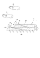
本発明の二段装入二段点火焼結法においては、図2に示したように、下段層10および上段層20の形成は、まず、含鉄原料、副原料、カーボン系凝結材を混合し一括してドラムミキサー1で造粒して造粒物とする。その後に、この一括して造粒された同じ造粒物を分割し、下段層厚h1と上段層厚h2が所定の比となるように第1および第2の配合原料に分配する。すなわち、下段層10を形成する第1の配合原料、上段層20を形成する第2の配合原料は、実質的に均質で、同一の配合原料である。
下段層10と上段層20を形成する配合原料として、一括造粒された均一で同じ原料をそれぞれに分配することにより、図1のように、第1のドラムミキサー1Aおよび第2のドラムミキサー2Aの二系統で造粒を行う必要がなくなる。すなわち、図2に示したように、ドラムミキサー1等の造粒機を一系統あるいは一つの造粒機にすることができる。また、詳細には後述するが、下段層厚h1と上段層厚h2の比を所定のものとし、下段層燃焼帯10A、上段層燃焼帯20Aを、同時に存在させるためにも、下段層10と上段層20を形成する配合原料は同一であることが必要である。
In the two-stage charging two-stage ignition sintering method of the present invention, as shown in FIG. 2, the
As a raw material for forming the
この本発明の二段装入二段点火焼結法における、下段層10を形成する第1の配合原料、上段層20を形成する第2の配合原料は、上記のように同じ材料を所定の量ずつに分割し、各層を形成するように分配したものである。この第1および第2の配合原料は、鉄鉱石、返鉱、製鋼ダスト等の含鉄原料に、石灰、フラックス等の副原料、粉コークス、無煙炭等のカーボン系凝結材を燃焼用の炭材として添加して造粒したものである。含鉄原料は、ヘマタイト、マグネタイト等の酸化鉱の他にも、ゲーサイト等の水酸化物を含む鉄鉱石等、どのような鉄鉱石でも使用することができる。
In the two-stage charging two-stage ignition sintering method of the present invention, the first compounding raw material for forming the
発明者らは、種々検討した結果、二段装入二段点火焼結法におけるNOx低減効果を最大限引き出せる条件を見出した。次に、図2のように下段層厚h1と上段層厚h2の比を所定のものとした経緯について詳細に説明する。 As a result of various studies, the inventors have found conditions that can maximize the NOx reduction effect in the two-stage charging two-stage ignition sintering method. Next, how the ratio between the lower layer thickness h1 and the upper layer thickness h2 is set to a predetermined value as shown in FIG. 2 will be described in detail.
多段装入多段点火焼結法による排ガス中のNOxの低減は、上段層燃焼帯20Aで生成した排ガス中のNOxが、下段層燃焼帯10Aで分解されることによる。そのため、DL式焼結機の機長方向の各位置において、層高方向に2ヶ所の燃焼帯(下段層燃焼帯10A、上段層燃焼帯20A)が時間的には同時に、空間的には層高方向に重複して存在すれば、下段層10から排出される排ガス中のNOxが低減される。言い換えると、上段層燃焼帯20Aの真下に下段層燃焼帯10Aが存在すればよい。
従って、DL式焼結機の機長方向において、層高方向に下段層燃焼帯10A、上段層燃焼帯20Aが重複して存在する機長方向の領域を拡大する重要性に着目した。
The reduction of NOx in the exhaust gas by the multi-stage charging / multistage ignition sintering method is based on the fact that the NOx in the exhaust gas generated in the
Therefore, attention was paid to the importance of expanding the region in the machine length direction where the
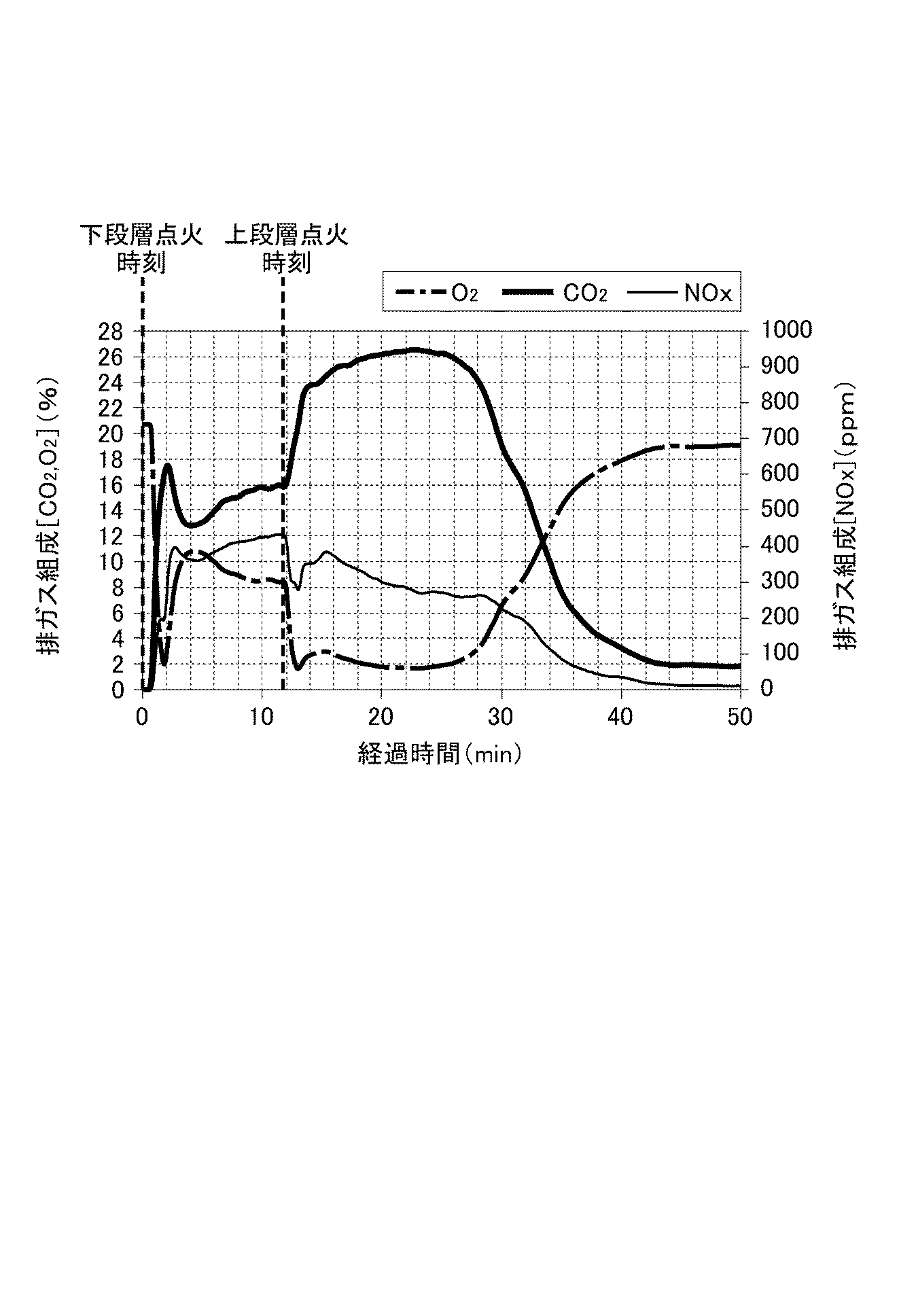
下段層燃焼帯10A、上段層燃焼帯20Aが層高方向に重複して存在する焼結条件を検討するため、風速一定鍋試験(1.3Nm3/min)において、一段装入一段点火した場合と、二段装入二段点火した場合の、排ガス組成の時間推移を測定した。一段装入一段点火において層厚は480mmとし、二段装入二段点火においては、下段層厚h1を一段装入一段点火の層厚と同じ480mmとし、その上の上段層厚h2を360mmとした。すなわち、図4において、下段層10と上段層20の合計層厚は840mmである。ここで、下段層10と上段層20を形成する際に、下段層10を形成する第1の配合原料、上段層20を形成する第2の配合原料は、まとめて一括で造粒し、一括で造粒した均一で同じ配合原料を必要量ずつ分配して使用した。結果を図3、4に示した。
In order to examine the sintering conditions in which the
図3は、一段装入一段点火の排ガス組成推移、図4は、二段装入二段点火の排ガス組成推移を示す。図3の経過時間0の時点における破線(補助線)は、原料充填層に点火したタイミングを示している。一方、図4の経過時間0の時点における破線(補助線)は、下段層10に点火したタイミングを示し、経過時間12min弱の時点における破線(補助線)は、上段層20に点火したタイミングを示している。
FIG. 3 shows the transition of the exhaust gas composition of the single-stage charging single-stage ignition, and FIG. 4 shows the transition of the exhaust gas composition of the two-stage charging two-stage ignition. The dashed line (auxiliary line) at the elapsed
NOx濃度の変化に注目すると、図3に示した一段装入一段点火については、炭材である粉コークスの燃焼が終了した経過時間30min程度までほぼ一定値で推移する。粉コークスの燃焼が終了したことは、排ガス組成中のCO2濃度が落ち込むことで判断できる。 Focusing on the change in the NOx concentration, the single-stage charging and single-stage ignition shown in FIG. 3 changes at a substantially constant value until the elapsed time of about 30 min after the completion of the combustion of the coke breeze as the carbonaceous material. Completion of the combustion of the coke breeze can be determined by a drop in the CO 2 concentration in the exhaust gas composition.
一方、図4に示した二段装入二段点火では、最初、下段層10の点火後、経過時間0から12min程度まで、一段装入一段点火と同様の水準(排ガス組成中のCO2の濃度として14から16%程度)で排ガス組成中のCO2濃度が推移する。その後、経過時間12min弱の時刻に上段層20に点火すると、この直後からCO2濃度が急激に増加し、経過時間32min程度の時点まで、上段層20点火前までのCO2の水準(排ガス組成中のCO2の濃度として14から16%程度)よりも、排ガス組成中のCO2濃度が10%以上高い水準で推移している。
On the other hand, in the two-stage charging two-stage ignition shown in FIG. 4, after the
上段層20の点火後、排ガス組成中のCO2濃度が上昇するのは、下段層10の焼結が進行すると同時に、上段層20の焼結も進行しているため、各々の層で発生するCO2が合計されるためである。すなわち、上段層20に点火した時点である経過時間約12min時点から32min時点までは、下段層10の焼結と上段層20の焼結は同時に進行するため、それぞれの燃焼帯である下段層燃焼帯10A、上段層燃焼帯20Aは、同時に存在している。
After the
下段層燃焼帯10A、上段層燃焼帯20Aが同時に存在し始める、上段層20への点火時刻(経過時間でいうと、下段層10の点火時刻0から12min弱経過した時点)以降の排ガス組成中のNOx濃度が急激に低下する。すなわち、下段層燃焼帯10A、上段層燃焼帯20Aが同時に存在することにより、ガス組成中のNOx濃度が減少する。
従って、層高方向に2ヶ所燃焼帯が存在することが重要であることが判る。
In the exhaust gas composition after the ignition time (in terms of elapsed time, less than 12 minutes from the
Therefore, it is important that two combustion zones exist in the height direction of the bed.
下段層燃焼帯10A、上段層燃焼帯20Aが存在する時間は、それぞれ、下段層厚h1/下段層10の燃焼前線降下速度、上段層厚h2/上段層20の燃焼前線降下速度で求まる(以降、燃焼前線降下速度を「FFS(Flame Front Speed)」という)。焼結全ストランドにおいて、二つの燃焼帯が上下段に重複して存在するには、上段層20および下段層10のFFSを把握し、それに基づいて上段層厚h2および下段層厚h1の層厚比を適正化することが重要である結論に至った。
The time during which the lower-
上段層20および下段層10のFFSについて考慮した先行技術は無く、今回初めて見出した。
図5に風速一定(1.3Nm3/min)条件下の鍋試験における燃焼前線の経時変化を示す。各層の層厚等の焼結条件は、図3、4と同様である。Case1は、一段装入一段点火、Case2、3は、二段装入二段点火焼結法を示している。図5において、Case1では、点火時刻を経過時間0とし、Case2、3では、下段層10に点火した時刻を経過時間0としている。また、Case2、3について、それぞれの破線(補助線)で示されているのは、上段層燃焼帯20Aの点火タイミングである。図5中のそれぞれの直線の傾きが、それぞれの原料充填層のFFSに相当する。
There is no prior art that considers the FFS of the
FIG. 5 shows the change over time of the combustion front in a pot test under a constant wind speed (1.3 Nm 3 / min). The sintering conditions such as the layer thickness of each layer are the same as in FIGS.
そこで、図5から得られたFFSを表1に示す。上段層20点火後の下段層10のFFSは、上段層20の点火前の下段層10のFFSよりも低下し、上段層20のFFSに対して75−80%である結果を得た。
Thus, Table 1 shows the FFS obtained from FIG. The FFS of the
その後、原料粒度、炭材配合比を変更し、FFSを検討したが、第1および第2の配合原料が、一括造粒された均一で同じものである条件下では、上段層20の点火後の下段層10のFFSは上段層20のFFSに対して70−90%に収まることが判明した。従って、下段層燃焼帯10A、上段層燃焼帯20Aが同時に存在する時間帯(=燃焼前線降下時間帯)を等しくするには、各々のFFSに合わせ、下段層厚h1を上段層厚h2に比べ低く、上段層厚h2の70−90%とすればよい。よって、本発明においては、図3〜5の知見をもとに、下段層厚h1/上段層厚h2=0.7〜0.9とした。
Thereafter, the raw material particle size and the carbon material blending ratio were changed to examine the FFS. However, under the condition that the first and second blended raw materials were uniform and the same as those obtained by the batch granulation, the
通常の二段装入二段点火焼結法では、上段層厚h2と下段層厚h1は等しくすることが前提である。上段層厚h2と下段層厚h1の層厚比率について開示されている従来技術としては、わずかに、特開昭62−109932号公報に、下段層厚h1の比率を高く、上段層厚h2:下段層厚h1の比として、1:1〜1:1.2とすることが記載されているのみである。 In the usual two-stage charging two-stage ignition sintering method, it is assumed that the upper layer thickness h2 and the lower layer thickness h1 are equal. As a prior art which discloses a layer thickness ratio between the upper layer thickness h2 and the lower layer thickness h1, Japanese Patent Application Laid-Open No. Sho 62-109932 discloses that the ratio of the lower layer thickness h1 is slightly increased and the upper layer thickness h2: It is only described that the ratio of the lower layer thickness h1 is 1: 1 to 1: 1.2.
上段層20と下段層10を形成する配合原料が異なると、下段層厚h1を上段層厚h2の70−90%としても、各々のFFSが変化し、下段層燃焼帯10A、上段層燃焼帯20Aが存在する時間帯が等しくならない。
もちろん、下段層10の点火後直ちに上段層20を形成する第2の配合原料を装入・点火することが望ましい。ただ、下段層10と上段層20の点火時間のタイムラグ(下段層10の点火完了から上段層20の点火開始までの時間間隔)を0とすることは、現実的に不可能であるので、このタイムラグは2min以内であれば、本発明の効果を損なわない。より好ましくは、タイムラグは1min以内である。また、各々の層について点火開始から点火完了までの時間は、通常どおり、0.4〜1minとすることが好ましい。
本発明は、かかる知見に基づいて完成した。
If the raw materials forming the
Of course, it is desirable to charge and ignite the second compounding material forming the
The present invention has been completed based on such findings.
なお、図2に示したドラムミキサー1による一括造粒は、アイリッヒミキサー(商品名)等の高速撹拌ミキサーでの一括造粒、パンペレタイザー等の皿型造粒機での一括造粒に置き換えることができる。あるいは、高速撹拌ミキサーと皿型造粒機を直列に並べて順次造粒し、造粒された均一な配合原料を下段層10と上段層20に分配してもよい。その場合、高速撹拌ミキサーと皿型造粒機の順序はどちらでもよい。高速撹拌ミキサーおよび/または皿型造粒機を採用すれば、撹拌力が高いので造粒強度が向上する。
The batch granulation by the
ドワイトロイド(DL)式焼結機による焼結鉱の製造方法を模擬し、以下の条件のφ300mmの焼結鍋試験により、本発明の二段装入二段点火焼結法の効果を検証した。 The effect of the two-stage charging two-stage ignition sintering method of the present invention was verified by simulating a method for producing a sintered ore using a Dwyroid (DL) type sintering machine and performing a sintering pot test of φ300 mm under the following conditions. .
1)原料配合
原料配合条件を表2に示す。
試験ケースは、一括造粒で二段装入二段点火を行うケースであり、造粒後に層厚に比して分割し、それぞれ第1の配合原料(下段層10用)と第2の配合原料(上段層20用)とした。なお、表2の赤鉄鉱A、Dの銘柄の違い、褐鉄鉱B、Cの銘柄の違いは産地の違いによる。また、橄欖岩はフラックスを形成する。赤鉄鉱精鉱は、粒度0.125mm以下の微粉鉱である。
1) Raw material blending Table 2 shows the raw material blending conditions.
The test case is a case in which two-stage charging and two-stage ignition are performed by batch granulation, and after granulation, the mixture is divided in proportion to the layer thickness, and the first compounding material (for the lower layer 10) and the second compounding This was used as a raw material (for the upper layer 20). In addition, the difference of brand of hematites A and D and the difference of brand of limonites B and C in Table 2 depend on the difference of the production place. Also, peridotite forms flux. Hematite concentrate is fine ore with a particle size of 0.125 mm or less.
2)造粒方法
ドラムミキサー(直径600mm、回転数25rpm)で4分間(min)混合後水分を添加してさらにドラムミキサーで4分間(min)処理した。水分は7.0%とした。
2) Granulation method After mixing for 4 minutes (min) using a drum mixer (
3)装入・点火方法
二段装入二段点火用に、直径300mm、高さ300mmの円柱形の下段用鍋と上段用鍋の2本を準備した。それぞれ所定の層厚に第1の配合原料(下段層10用)および第2の配合原料(上段層20用)を装入しておく。まず下段に下段用鍋をセットして、1100℃1分間(min)点火した。点火終了後、直ちに上段用鍋を下段用鍋の上にセットして、1100℃1分間(min)点火した。ここで、下段層10の点火終了から上段層20の点火開始までに30秒要した。
3) Charging / Ignition Method For the two-stage charging and two-stage ignition, two cylindrical pans having a diameter of 300 mm and a height of 300 mm, namely, a lower pan and an upper pan were prepared. A first compounding material (for the lower layer 10) and a second compounding material (for the upper layer 20) are charged to a predetermined layer thickness. First, the lower pot was set on the lower row, and the ignition was performed at 1100 ° C. for 1 minute (min). Immediately after the completion of the ignition, the upper pan was set on the lower pan and ignited at 1100 ° C. for 1 minute (min). Here, it took 30 seconds from the end of ignition of the
なお、各ケースで下段層10、上段層20の層厚が異なるが、点火は以下のように行った。
まず、第1の配合原料(下段層10用)は、下段用鍋の上面より所定量分だけ低い位置が、原料充填層の上面となるように調整して下段層10の点火を行った、そして、下段層10の点火後、直ちに下段用鍋の上面まで原料を追加してから、予め、第2の配合原料(上段層20用)を装入していた上段用鍋を載せて上段層20に点火した。すなわち、下段層厚h1は、下段層10の点火前までに下段用鍋に装入した層厚であり、上段層厚h2は、下段層10の点火後に下段用鍋に追加した分と、上段用鍋に装入した分の和である。
吸引風量は、点火開始から1.3Nm3/min一定とした。
In addition, although the layer thickness of the
First, the first compounded raw material (for the lower layer 10) was adjusted so that a position lower than the upper surface of the lower pot by a predetermined amount was the upper surface of the raw material filling layer, and the
The suction air volume was kept constant at 1.3 Nm 3 / min from the start of ignition.
4)焼結終了タイミングおよび焼結時間
下段層10からの排ガス温度がピークとなった時刻から3分(min)後に送風を停止し、焼結終了とした。焼結時間は、下段層10に点火した時刻から下段層10からの排ガス温度がピークとなった時刻までの所要時間とした。
4) Sintering end timing and sintering time Three minutes (min) from the time when the temperature of the exhaust gas from the
5)NOx評価方法
排ガスNOx濃度は、焼結排ガスを分取し分析計へ供して測定した。
排ガスNOx排出量の評価指標として(1)式で計算されるNOx転換率(ηNO:100×[排ガス中のNOx生成量/(排ガス中のCOおよびCO2生成量)]/[窒素入量/(カーボン入量)])を用いた。
ここで、排ガス中に含まれるCOおよびCO2は点火ガス、粉コークスおよび石灰石由来とみなし、NOxは全て粉コークスに由来すると仮定して計算を行った。
5) NOx evaluation method The exhaust gas NOx concentration was measured by separating a sintered exhaust gas and providing it to an analyzer.
NOx conversion rate is calculated by equation (1) as an evaluation index of the exhaust gas NOx emissions (ηNO: 100 × [NOx generation amount in the exhaust gas / (CO and CO 2 generation amount in the exhaust gas)] / [nitrogen Iriryou / (Carbon content)]) was used.
Here, CO and CO 2 contained in the exhaust gas were regarded as being derived from ignition gas, coke breeze and limestone, and the calculation was performed on the assumption that all NOx was derived from coke breeze.
ηNO=100×[NOx/(CO+CO2)]/[NCOKE/(CLPG+CCOKE+CCLS)]・・・・・・(1) ηNO = 100 × [NOx / (CO + CO 2 )] / [N COKE / (C LPG + C COKE + C CLS )] (1)
ここで、
ηNO :NOx転換率(%)
NOx :排ガスNOx(%)
CO :排ガスCO(%)
CO2 :排ガスCO2(%)
NCOKE :単位時間あたりの粉コークス由来の窒素入量(mol)
CLPG :単位時間あたりの点火ガス由来のカーボン入量(mol)
CCOKE :単位時間あたりの粉コークス由来のカーボン入量(mol)
CCLS :単位時間あたりの石灰石由来のカーボン入量(mol)
here,
ηNO: NOx conversion rate (%)
NOx: Exhaust gas NOx (%)
CO: Exhaust gas CO (%)
CO 2 : exhaust gas CO 2 (%)
N COKE : Nitrogen input from coke breeze per unit time (mol)
C LPG : Carbon input from ignition gas per unit time (mol)
C COKE : Input amount of carbon derived from coke breeze per unit time (mol)
C CLS : Limestone-derived carbon input per unit time (mol)
6)試験水準
試験ケースを表3の上段に示す。すべてのケースで、一括造粒した後分割、各層を形成するように分配して二段装入二段点火した(図2)。
ケースの差異は、下段層厚h1/上段層厚h2の比率であり、
比較例1 下段層厚h1/上段層厚h2=1.0
発明例1〜3 下段層厚h1/上段層厚h2=0.9、0.8、0.7
比較例2 下段層厚h1/上段層厚h2=0.6
焼結時の吸引風量は、点火開始から1.3Nm3/min一定とした。
下段層10からの排ガス温度がピークとなった時刻から3min後に送風を停止し、焼結終了とした。
6) Test level Table 3 shows the test cases. In all cases, two-stage charging and two-stage ignition were performed after the granulation was performed at once, divided, and distributed to form each layer (FIG. 2).
The difference between the cases is the ratio of the lower layer thickness h1 / the upper layer thickness h2,
Comparative Example 1 Lower layer thickness h1 / upper layer thickness h2 = 1.0
Inventive Examples 1-3 Lower layer thickness h1 / upper layer thickness h2 = 0.9, 0.8, 0.7
Comparative Example 2 Lower layer thickness h1 / upper layer thickness h2 = 0.6
The suction air volume at the time of sintering was kept constant at 1.3 Nm 3 / min from the start of ignition.
Blowing was stopped 3 minutes after the time when the temperature of the exhaust gas from the
7)試験結果
試験結果を表3の下段に示す。
7) Test results The test results are shown in the lower part of Table 3.
比較例1は、下段層厚h1/上段層厚h2が0.9を超えているので、下段層10の燃焼前線降下時間帯が長くなりすぎ、上段層20の燃焼前線降下時間帯との重複時間(上下段共に燃焼前線が降下している時間長さ(a))が短い。その結果、下段層燃焼帯10Aと、上段層燃焼帯20Aが層高方向に同時に存在する時間が短くなり、NOx転換率が高くなった。
In Comparative Example 1, since the lower layer thickness h1 / upper layer thickness h2 exceeded 0.9, the combustion front descent time zone of the
比較例2は、下段層厚h1/上段層厚h2が0.7を下回っているので、上段層20の燃焼前線降下時間帯が長くなりすぎ、下段層10の燃焼前線降下時間帯との重複時間(上下段共に燃焼前線が降下している時間長さ(a))が短い。その結果、下段層燃焼帯10Aと、上段層燃焼帯20Aが層高方向に同時に存在する時間が短くなり、NOx転換率が高くなった。
In Comparative Example 2, since the lower layer thickness h1 / upper layer thickness h2 was less than 0.7, the combustion front descent time zone of the
これに対して、発明例1〜3は、上下段共に燃焼前線が降下している時間長さ(a)(min)が長く、上段、下段の少なくとも一方の燃焼前線が降下している時間長さ(b)(min)に対する比が高い。その結果、NOx転換率が低くなった。
以上より、上段下段の層厚比の適正化によって、上下段共に燃焼前線が降下している時間長さ(a)(min)を長く取ることで、NOx転換率を下げることが可能である。
On the other hand, in Invention Examples 1 to 3, the time length (a) (min) in which the combustion front is falling in both the upper and lower stages is long, and the time length in which at least one of the upper and lower combustion fronts is falling. The ratio with respect to (b) (min) is high. As a result, the NOx conversion rate decreased.
As described above, by optimizing the layer thickness ratio of the upper and lower stages, it is possible to reduce the NOx conversion rate by increasing the time length (a) (min) during which the combustion front is falling in both the upper and lower stages.
本発明によれば、二段装入二段点火焼結法において、NOxの生成を低減できるので、環境にやさしく、NOx処理の負担を低減できるため、焼結鉱の製造方法の低コスト化が可能となるという特段の産業上の利用性を有する。 According to the present invention, in the two-stage charging two-stage ignition sintering method, the generation of NOx can be reduced, so that it is environmentally friendly and the burden of NOx treatment can be reduced. It has special industrial applicability that makes it possible.
1…ドラムミキサー、1A…第1のドラムミキサー、1B…第1のホッパ、1C…第1の点火器、10…下段層、10A…下段層燃焼帯、2A…第2のドラムミキサー、2B…第2のホッパ、2C…第2の点火器、20…上段層、20A…上段層燃焼帯、3…焼結部、5…下流方向、6…下方吸引
DESCRIPTION OF
Claims (1)
含鉄原料、副原料、カーボン系凝結材を混合して造粒した第1の配合原料を供給して下段層を形成し、
前記下段層の上部から点火し、下方から空気を吸引することにより前記下段層の焼結を開始し、
点火後の前記下段層上に、含鉄原料、副原料、カーボン系凝結材を混合して造粒した第2の配合原料をさらに供給して上段層を形成し、
前記上段層に点火し、下方から空気を吸引することにより前記上段層の焼結を開始し、
その後も下方から空気を吸引することにより、前記上段層および前記下段層を焼結する二段装入二段点火焼結法による焼結鉱の製造方法であって、
前記下段層および前記上段層は、前記含鉄原料、前記副原料、前記カーボン系凝結材を混合し一括して造粒し、配合原料とした後に、前記配合原料を、前記第1の配合原料と前記第2の配合原料に分配し、下段層厚h1/上段層厚h2=0.7〜0.9とされていることを特徴とする焼結鉱の製造方法。 Pallets that make up the Dwyroid (DL) sintering machine
The lower layer is formed by supplying the first compounded raw material obtained by mixing and granulating the iron-containing raw material, the auxiliary raw material, and the carbon-based coagulant,
Ignition from the upper part of the lower layer, start sintering of the lower layer by sucking air from below,
On the lower layer after ignition, an iron-containing raw material, an auxiliary material, and a second blended raw material obtained by mixing and granulating a carbon-based coagulant are further supplied to form an upper layer,
Ignition the upper layer and start sintering the upper layer by sucking air from below,
A method for producing a sintered ore by a two-stage charging two-stage ignition sintering method of thereafter sintering the upper layer and the lower layer by sucking air from below,
The lower layer and the upper layer are obtained by mixing the iron-containing raw material, the auxiliary raw material, and the carbon-based coagulant, granulating them at once, and forming a compounded raw material, and then mixing the compounded raw material with the first compounded raw material. A method for producing a sintered ore, wherein the method is distributed to the second compounding raw material and the lower layer thickness h1 / the upper layer thickness h2 is set to 0.7 to 0.9.
Priority Applications (1)
| Application Number | Priority Date | Filing Date | Title |
|---|---|---|---|
| JP2018126495A JP7043994B2 (en) | 2018-07-03 | 2018-07-03 | Sintered ore manufacturing method |
Applications Claiming Priority (1)
| Application Number | Priority Date | Filing Date | Title |
|---|---|---|---|
| JP2018126495A JP7043994B2 (en) | 2018-07-03 | 2018-07-03 | Sintered ore manufacturing method |
Publications (2)
| Publication Number | Publication Date |
|---|---|
| JP2020007577A true JP2020007577A (en) | 2020-01-16 |
| JP7043994B2 JP7043994B2 (en) | 2022-03-30 |
Family
ID=69150721
Family Applications (1)
| Application Number | Title | Priority Date | Filing Date |
|---|---|---|---|
| JP2018126495A Active JP7043994B2 (en) | 2018-07-03 | 2018-07-03 | Sintered ore manufacturing method |
Country Status (1)
| Country | Link |
|---|---|
| JP (1) | JP7043994B2 (en) |
Cited By (1)
| Publication number | Priority date | Publication date | Assignee | Title |
|---|---|---|---|---|
| CN115584389A (en) * | 2022-10-28 | 2023-01-10 | 湖南华菱湘潭钢铁有限公司 | Fuel layered sintering method for super-thick material layer |
Citations (4)
| Publication number | Priority date | Publication date | Assignee | Title |
|---|---|---|---|---|
| JPH06330190A (en) * | 1993-05-26 | 1994-11-29 | Sumitomo Metal Ind Ltd | Two step ignition type production method of sintered ore |
| JPH09209050A (en) * | 1996-02-05 | 1997-08-12 | Nippon Steel Corp | Method for producing sinter with high layer thickness |
| JP2000017343A (en) * | 1998-07-03 | 2000-01-18 | Nippon Steel Corp | Method for two-stage ignition production of sintered ore |
| JP2015157980A (en) * | 2014-02-24 | 2015-09-03 | Jfeスチール株式会社 | Method for producing sintered ore |
-
2018
- 2018-07-03 JP JP2018126495A patent/JP7043994B2/en active Active
Patent Citations (4)
| Publication number | Priority date | Publication date | Assignee | Title |
|---|---|---|---|---|
| JPH06330190A (en) * | 1993-05-26 | 1994-11-29 | Sumitomo Metal Ind Ltd | Two step ignition type production method of sintered ore |
| JPH09209050A (en) * | 1996-02-05 | 1997-08-12 | Nippon Steel Corp | Method for producing sinter with high layer thickness |
| JP2000017343A (en) * | 1998-07-03 | 2000-01-18 | Nippon Steel Corp | Method for two-stage ignition production of sintered ore |
| JP2015157980A (en) * | 2014-02-24 | 2015-09-03 | Jfeスチール株式会社 | Method for producing sintered ore |
Cited By (1)
| Publication number | Priority date | Publication date | Assignee | Title |
|---|---|---|---|---|
| CN115584389A (en) * | 2022-10-28 | 2023-01-10 | 湖南华菱湘潭钢铁有限公司 | Fuel layered sintering method for super-thick material layer |
Also Published As
| Publication number | Publication date |
|---|---|
| JP7043994B2 (en) | 2022-03-30 |
Similar Documents
| Publication | Publication Date | Title |
|---|---|---|
| JPH05311257A (en) | Production of sintered ore | |
| JP7207147B2 (en) | Method for producing sintered ore | |
| JP2021120479A (en) | Method for producing sintered ore and sintering machine | |
| JP2023047300A (en) | Manufacturing method of sintered ore | |
| JP2015157980A (en) | Method for producing sintered ore | |
| JP2014214334A (en) | Method for manufacturing sintered ore | |
| JP7328537B2 (en) | Method for producing sintered ore | |
| JP7043994B2 (en) | Sintered ore manufacturing method | |
| JP2018178148A (en) | Method of producing sintered ore | |
| JP6848618B2 (en) | Sintered ore manufacturing method | |
| JP2013023729A (en) | Method for producing sintered ore | |
| JP2020158849A (en) | Combustion promotion method of carbonaceous material in sintering | |
| JP2789994B2 (en) | Two-stage ignition ore manufacturing method | |
| JP7095446B2 (en) | Sintered ore manufacturing method | |
| JP6477167B2 (en) | Method for producing sintered ore | |
| JP4984488B2 (en) | Method for producing semi-reduced sintered ore | |
| JP4918754B2 (en) | Semi-reduced sintered ore and method for producing the same | |
| JP6885164B2 (en) | Sintered ore manufacturing method | |
| JP5733075B2 (en) | Method for producing sintered ore | |
| JP2014189889A (en) | Method for producing sintered ore for iron making | |
| JP2945774B2 (en) | Sinter production method | |
| JP2012026016A (en) | Method of manufacturing sintered ore | |
| JP2697550B2 (en) | Two-stage ignition ore manufacturing method | |
| EP4692382A1 (en) | Sintered ore production method | |
| JPS6260829A (en) | Two-stage-ignition sintering method for raw material for iron manufacture |
Legal Events
| Date | Code | Title | Description |
|---|---|---|---|
| A621 | Written request for application examination |
Free format text: JAPANESE INTERMEDIATE CODE: A621 Effective date: 20210303 |
|
| A977 | Report on retrieval |
Free format text: JAPANESE INTERMEDIATE CODE: A971007 Effective date: 20220112 |
|
| TRDD | Decision of grant or rejection written | ||
| A01 | Written decision to grant a patent or to grant a registration (utility model) |
Free format text: JAPANESE INTERMEDIATE CODE: A01 Effective date: 20220215 |
|
| A61 | First payment of annual fees (during grant procedure) |
Free format text: JAPANESE INTERMEDIATE CODE: A61 Effective date: 20220228 |
|
| R151 | Written notification of patent or utility model registration |
Ref document number: 7043994 Country of ref document: JP Free format text: JAPANESE INTERMEDIATE CODE: R151 |