JP2020007634A - Electrochemical hydrogen pump - Google Patents
Electrochemical hydrogen pump Download PDFInfo
- Publication number
- JP2020007634A JP2020007634A JP2019110245A JP2019110245A JP2020007634A JP 2020007634 A JP2020007634 A JP 2020007634A JP 2019110245 A JP2019110245 A JP 2019110245A JP 2019110245 A JP2019110245 A JP 2019110245A JP 2020007634 A JP2020007634 A JP 2020007634A
- Authority
- JP
- Japan
- Prior art keywords
- hydrogen pump
- cathode
- pump unit
- diffusion layer
- gas diffusion
- Prior art date
- Legal status (The legal status is an assumption and is not a legal conclusion. Google has not performed a legal analysis and makes no representation as to the accuracy of the status listed.)
- Withdrawn
Links
Images



Classifications
-
- C—CHEMISTRY; METALLURGY
- C25—ELECTROLYTIC OR ELECTROPHORETIC PROCESSES; APPARATUS THEREFOR
- C25B—ELECTROLYTIC OR ELECTROPHORETIC PROCESSES FOR THE PRODUCTION OF COMPOUNDS OR NON-METALS; APPARATUS THEREFOR
- C25B1/00—Electrolytic production of inorganic compounds or non-metals
- C25B1/01—Products
- C25B1/02—Hydrogen or oxygen
- C25B1/04—Hydrogen or oxygen by electrolysis of water
-
- C—CHEMISTRY; METALLURGY
- C25—ELECTROLYTIC OR ELECTROPHORETIC PROCESSES; APPARATUS THEREFOR
- C25B—ELECTROLYTIC OR ELECTROPHORETIC PROCESSES FOR THE PRODUCTION OF COMPOUNDS OR NON-METALS; APPARATUS THEREFOR
- C25B9/00—Cells or assemblies of cells; Constructional parts of cells; Assemblies of constructional parts, e.g. electrode-diaphragm assemblies; Process-related cell features
- C25B9/70—Assemblies comprising two or more cells
- C25B9/73—Assemblies comprising two or more cells of the filter-press type
-
- F—MECHANICAL ENGINEERING; LIGHTING; HEATING; WEAPONS; BLASTING
- F04—POSITIVE - DISPLACEMENT MACHINES FOR LIQUIDS; PUMPS FOR LIQUIDS OR ELASTIC FLUIDS
- F04B—POSITIVE-DISPLACEMENT MACHINES FOR LIQUIDS; PUMPS
- F04B37/00—Pumps having pertinent characteristics not provided for in, or of interest apart from, groups F04B25/00 - F04B35/00
- F04B37/02—Pumps having pertinent characteristics not provided for in, or of interest apart from, groups F04B25/00 - F04B35/00 for evacuating by absorption or adsorption
- F04B37/04—Selection of specific absorption or adsorption materials
-
- H—ELECTRICITY
- H01—ELECTRIC ELEMENTS
- H01M—PROCESSES OR MEANS, e.g. BATTERIES, FOR THE DIRECT CONVERSION OF CHEMICAL ENERGY INTO ELECTRICAL ENERGY
- H01M8/00—Fuel cells; Manufacture thereof
- H01M8/24—Grouping of fuel cells, e.g. stacking of fuel cells
- H01M8/2465—Details of groupings of fuel cells
- H01M8/247—Arrangements for tightening a stack, for accommodation of a stack in a tank or for assembling different tanks
- H01M8/248—Means for compression of the fuel cell stacks
-
- C—CHEMISTRY; METALLURGY
- C25—ELECTROLYTIC OR ELECTROPHORETIC PROCESSES; APPARATUS THEREFOR
- C25B—ELECTROLYTIC OR ELECTROPHORETIC PROCESSES FOR THE PRODUCTION OF COMPOUNDS OR NON-METALS; APPARATUS THEREFOR
- C25B1/00—Electrolytic production of inorganic compounds or non-metals
- C25B1/01—Products
- C25B1/02—Hydrogen or oxygen
-
- C—CHEMISTRY; METALLURGY
- C25—ELECTROLYTIC OR ELECTROPHORETIC PROCESSES; APPARATUS THEREFOR
- C25B—ELECTROLYTIC OR ELECTROPHORETIC PROCESSES FOR THE PRODUCTION OF COMPOUNDS OR NON-METALS; APPARATUS THEREFOR
- C25B9/00—Cells or assemblies of cells; Constructional parts of cells; Assemblies of constructional parts, e.g. electrode-diaphragm assemblies; Process-related cell features
- C25B9/17—Cells comprising dimensionally-stable non-movable electrodes; Assemblies of constructional parts thereof
- C25B9/19—Cells comprising dimensionally-stable non-movable electrodes; Assemblies of constructional parts thereof with diaphragms
-
- C—CHEMISTRY; METALLURGY
- C25—ELECTROLYTIC OR ELECTROPHORETIC PROCESSES; APPARATUS THEREFOR
- C25B—ELECTROLYTIC OR ELECTROPHORETIC PROCESSES FOR THE PRODUCTION OF COMPOUNDS OR NON-METALS; APPARATUS THEREFOR
- C25B9/00—Cells or assemblies of cells; Constructional parts of cells; Assemblies of constructional parts, e.g. electrode-diaphragm assemblies; Process-related cell features
- C25B9/17—Cells comprising dimensionally-stable non-movable electrodes; Assemblies of constructional parts thereof
- C25B9/19—Cells comprising dimensionally-stable non-movable electrodes; Assemblies of constructional parts thereof with diaphragms
- C25B9/23—Cells comprising dimensionally-stable non-movable electrodes; Assemblies of constructional parts thereof with diaphragms comprising ion-exchange membranes in or on which electrode material is embedded
-
- F—MECHANICAL ENGINEERING; LIGHTING; HEATING; WEAPONS; BLASTING
- F04—POSITIVE - DISPLACEMENT MACHINES FOR LIQUIDS; PUMPS FOR LIQUIDS OR ELASTIC FLUIDS
- F04B—POSITIVE-DISPLACEMENT MACHINES FOR LIQUIDS; PUMPS
- F04B37/00—Pumps having pertinent characteristics not provided for in, or of interest apart from, groups F04B25/00 - F04B35/00
- F04B37/10—Pumps having pertinent characteristics not provided for in, or of interest apart from, groups F04B25/00 - F04B35/00 for special use
- F04B37/18—Pumps having pertinent characteristics not provided for in, or of interest apart from, groups F04B25/00 - F04B35/00 for special use for specific elastic fluids
-
- F—MECHANICAL ENGINEERING; LIGHTING; HEATING; WEAPONS; BLASTING
- F04—POSITIVE - DISPLACEMENT MACHINES FOR LIQUIDS; PUMPS FOR LIQUIDS OR ELASTIC FLUIDS
- F04B—POSITIVE-DISPLACEMENT MACHINES FOR LIQUIDS; PUMPS
- F04B43/00—Machines, pumps, or pumping installations having flexible working members
- F04B43/02—Machines, pumps, or pumping installations having flexible working members having plate-like flexible members, e.g. diaphragms
- F04B43/04—Pumps having electric drive
- F04B43/043—Micropumps
- F04B43/046—Micropumps with piezoelectric drive
-
- H—ELECTRICITY
- H01—ELECTRIC ELEMENTS
- H01M—PROCESSES OR MEANS, e.g. BATTERIES, FOR THE DIRECT CONVERSION OF CHEMICAL ENERGY INTO ELECTRICAL ENERGY
- H01M8/00—Fuel cells; Manufacture thereof
- H01M8/10—Fuel cells with solid electrolytes
- H01M2008/1095—Fuel cells with polymeric electrolytes
-
- Y—GENERAL TAGGING OF NEW TECHNOLOGICAL DEVELOPMENTS; GENERAL TAGGING OF CROSS-SECTIONAL TECHNOLOGIES SPANNING OVER SEVERAL SECTIONS OF THE IPC; TECHNICAL SUBJECTS COVERED BY FORMER USPC CROSS-REFERENCE ART COLLECTIONS [XRACs] AND DIGESTS
- Y02—TECHNOLOGIES OR APPLICATIONS FOR MITIGATION OR ADAPTATION AGAINST CLIMATE CHANGE
- Y02E—REDUCTION OF GREENHOUSE GAS [GHG] EMISSIONS, RELATED TO ENERGY GENERATION, TRANSMISSION OR DISTRIBUTION
- Y02E60/00—Enabling technologies; Technologies with a potential or indirect contribution to GHG emissions mitigation
- Y02E60/30—Hydrogen technology
- Y02E60/36—Hydrogen production from non-carbon containing sources, e.g. by water electrolysis
-
- Y—GENERAL TAGGING OF NEW TECHNOLOGICAL DEVELOPMENTS; GENERAL TAGGING OF CROSS-SECTIONAL TECHNOLOGIES SPANNING OVER SEVERAL SECTIONS OF THE IPC; TECHNICAL SUBJECTS COVERED BY FORMER USPC CROSS-REFERENCE ART COLLECTIONS [XRACs] AND DIGESTS
- Y02—TECHNOLOGIES OR APPLICATIONS FOR MITIGATION OR ADAPTATION AGAINST CLIMATE CHANGE
- Y02E—REDUCTION OF GREENHOUSE GAS [GHG] EMISSIONS, RELATED TO ENERGY GENERATION, TRANSMISSION OR DISTRIBUTION
- Y02E60/00—Enabling technologies; Technologies with a potential or indirect contribution to GHG emissions mitigation
- Y02E60/30—Hydrogen technology
- Y02E60/50—Fuel cells
Landscapes
- Engineering & Computer Science (AREA)
- Chemical & Material Sciences (AREA)
- Chemical Kinetics & Catalysis (AREA)
- Electrochemistry (AREA)
- Organic Chemistry (AREA)
- Materials Engineering (AREA)
- Metallurgy (AREA)
- General Engineering & Computer Science (AREA)
- Mechanical Engineering (AREA)
- Inorganic Chemistry (AREA)
- Life Sciences & Earth Sciences (AREA)
- Manufacturing & Machinery (AREA)
- Sustainable Development (AREA)
- Sustainable Energy (AREA)
- General Chemical & Material Sciences (AREA)
- Electrolytic Production Of Non-Metals, Compounds, Apparatuses Therefor (AREA)
- Fuel Cell (AREA)
Abstract
【課題】水素ポンプユニットを構成する部材間の接触抵抗の増加を簡易かつ適切に抑制し得る電気化学式水素ポンプを提供する。【解決手段】少なくとも3つ以上の積層された水素ポンプユニット100の締結器25の締結によりカソードガス拡散層が圧縮される厚みの大きさは、積層された水素ポンプユニットの両端の少なくとも一方の端に位置する水素ポンプユニットのカソードガス拡散層の方が、積層された水素ポンプユニットの両端に位置しない水素ポンプユニットのカソードガス拡散層よりも大きい。【選択図】図2AAn electrochemical hydrogen pump capable of easily and appropriately suppressing an increase in contact resistance between members constituting a hydrogen pump unit. Kind Code: A1 A cathode gas diffusion layer is compressed by fastening fasteners of at least three or more stacked hydrogen pump units, and the thickness of the compressed gas layer is at least one end of both ends of the stacked hydrogen pump units. Is larger than the cathode gas diffusion layers of the hydrogen pump units that are not located at both ends of the stacked hydrogen pump units. [Selection diagram] FIG. 2A
Description
本開示は電気化学式水素ポンプに関する。 The present disclosure relates to an electrochemical hydrogen pump.
近年、地球の温暖化などの環境問題、石油資源の枯渇などのエネルギー問題から、化石燃料に代わるクリーンな代替エネルギー源として、水素が注目されている。水素は燃焼しても基本的に水しか放出せず、地球温暖化の原因となる二酸化炭素が排出されずかつ窒素酸化物などもほとんど排出されないので、クリーンエネルギーとして期待されている。また、水素を燃料として高効率に利用する装置として、例えば、燃料電池があり、自動車用電源向け、家庭用自家発電向けに開発および普及が進んでいる。 In recent years, hydrogen has been attracting attention as a clean alternative energy source to fossil fuels due to environmental problems such as global warming and energy problems such as depletion of petroleum resources. Hydrogen basically emits only water when burned, does not emit carbon dioxide, which causes global warming, and emits almost no nitrogen oxides, so it is expected as clean energy. Further, as a device that uses hydrogen as a fuel with high efficiency, for example, there is a fuel cell, which is being developed and spread for a power source for automobiles and a private power generator for home use.
来るべき水素社会では、水素を製造することに加えて、水素を高密度で貯蔵し、小容量かつ低コストで輸送または利用し得る技術開発が求められている。特に、分散型のエネルギー源となる燃料電池の普及促進には、水素供給インフラを整備する必要がある。また、水素を安定的に供給するために、高純度の水素を製造、精製、高密度貯蔵する様々な提案が行われている。 In the coming hydrogen society, in addition to producing hydrogen, there is a demand for technology development that can store hydrogen at a high density and transport or use it at a small capacity and at low cost. In particular, in order to promote the spread of fuel cells, which are distributed energy sources, it is necessary to improve the hydrogen supply infrastructure. In order to supply hydrogen stably, various proposals for producing, purifying, and storing high-purity hydrogen at high density have been made.
例えば、特許文献1では、固体高分子電解質膜、給電体およびセパレーターの積層体をエンドプレートで挟んだ状態で、エンドプレートを貫通する締結ボルトにより積層体が締結された高圧水素製造装置が提案されている。この高圧水素製造装置において、高圧側のカソード給電体および低圧側のアノード給電体間に、所定圧以上の差圧が生じると、固体高分子電解質膜および低圧側のアノード給電体が変形する。すると、高圧側のカソード給電体および固体高分子電解質膜間の接触抵抗が増加する。 For example, Patent Literature 1 proposes a high-pressure hydrogen production apparatus in which a laminate of a solid polymer electrolyte membrane, a power supply, and a separator is sandwiched between end plates, and the laminate is fastened by fastening bolts penetrating the end plates. ing. In this high-pressure hydrogen production apparatus, when a pressure difference equal to or more than a predetermined pressure is generated between the high-pressure side cathode power supply and the low-pressure side anode power supply, the solid polymer electrolyte membrane and the low-pressure side anode power supply are deformed. Then, the contact resistance between the cathode power feeder on the high voltage side and the solid polymer electrolyte membrane increases.
そこで、特許文献1の高圧水素製造装置に、固体高分子電解質膜および低圧側のアノード給電体が変形しても、高圧側のカソード給電体を固体高分子電解質膜に押圧して密着させる皿バネ、コイルバネなどの押圧手段が設けられている。これにより、高圧側のカソード給電体および固体高分子電解質膜間の接触抵抗の増加を抑制することができる。 Therefore, in the high-pressure hydrogen production apparatus of Patent Document 1, a coned disc spring that presses the high-voltage cathode power feeder against the solid polymer electrolyte membrane even if the solid polymer electrolyte membrane and the low-pressure anode feeder are deformed. And a pressing means such as a coil spring. Thereby, it is possible to suppress an increase in contact resistance between the high-voltage side cathode power supply and the solid polymer electrolyte membrane.
しかし、従来例は、カソードのガス圧が高圧になる場合のカソードセパレーターおよびカソード給電体間の接触抵抗の増加については十分に検討されていない。 However, in the conventional example, the increase in the contact resistance between the cathode separator and the cathode power supply when the gas pressure of the cathode becomes high has not been sufficiently studied.
本開示の一態様(aspect)は、このような事情に鑑みてなされたものであり、従来に比べて、水素ポンプユニットを構成する部材間の接触抵抗の増加を簡易かつ適切に抑制し得る電気化学式水素ポンプを提供する。 One aspect (aspect) of the present disclosure has been made in view of such circumstances, and compared with the related art, an electric power that can easily and appropriately suppress an increase in contact resistance between members constituting a hydrogen pump unit. Provide a chemical hydrogen pump.
上記課題を解決するため、本開示の一態様の電気化学式水素ポンプは、電解質膜、前記電解質膜の一方の主面上に設けられたアノード触媒層、前記電解質膜の他方の主面上に設けられたカソード触媒層、前記アノード触媒層上に設けられたアノードガス拡散層、前記アノードガス拡散層上に設けられたアノードセパレーター、前記カソード触媒層上に設けられたカソードガス拡散層、および前記カソードガス拡散層上に設けられたカソードセパレーターを備える水素ポンプユニットと、少なくとも3つ以上の積層された前記水素ポンプユニットの積層方向の両端上に設けられた第1の端板および第2の端板と、前記第1の端板と前記第2の端板を締結して、前記水素ポンプユニットを積層方向に圧縮する締結器と、を備え、少なくとも3つ以上の積層された前記水素ポンプユニットの前記カソードガス拡散層から流出するカソードガスが流れるカソードガス流路は連通されており、前記締結器の締結により前記カソードガス拡散層が圧縮される厚みの大きさは、前記積層された水素ポンプユニットの両端の少なくとも一方の端に位置する前記水素ポンプユニットの前記カソードガス拡散層の方が、前記積層された水素ポンプユニットの両端に位置しない前記水素ポンプユニットの前記カソードガス拡散層よりも大きい。 In order to solve the above problem, an electrochemical hydrogen pump according to one embodiment of the present disclosure includes an electrolyte membrane, an anode catalyst layer provided on one main surface of the electrolyte membrane, and an anode catalyst layer provided on the other main surface of the electrolyte membrane. Cathode catalyst layer, an anode gas diffusion layer provided on the anode catalyst layer, an anode separator provided on the anode gas diffusion layer, a cathode gas diffusion layer provided on the cathode catalyst layer, and the cathode A hydrogen pump unit including a cathode separator provided on a gas diffusion layer, and a first end plate and a second end plate provided on both ends in a stacking direction of at least three or more of the stacked hydrogen pump units. And a fastener for fastening the first end plate and the second end plate and compressing the hydrogen pump unit in the stacking direction. The cathode gas passage through which the cathode gas flowing out of the cathode gas diffusion layer of the hydrogen pump unit in which the cathode gas diffusion layer flows is communicated, and the cathode gas diffusion layer is compressed by fastening the fastener so that the thickness of the cathode gas diffusion layer is reduced. The cathode gas diffusion layer of the hydrogen pump unit located at at least one end of both ends of the stacked hydrogen pump unit, the hydrogen pump unit of the hydrogen pump unit is not located at both ends of the stacked hydrogen pump unit It is larger than the cathode gas diffusion layer.
本開示の一態様の電気化学式水素ポンプは、従来に比べて、水素ポンプユニットを構成する部材間の接触抵抗の増加を簡易かつ適切に抑制し得る。 The electrochemical hydrogen pump according to one embodiment of the present disclosure can easily and appropriately suppress an increase in contact resistance between members included in a hydrogen pump unit as compared with the related art.
特許文献1の高圧水素製造装置では、エンドプレートを貫通する締結ボルトにより積層体が締結され、積層方向に圧縮されている。しかしながら、発明者らが鋭意検討した結果、カソードのガス圧が高圧であるため、カソードセパレーターが、これに近接するエンドプレート側に膨らむように変形し、これに伴いエンドプレートも積層体側と反対の方向である外側に向け膨らむよう変形することを見出した。また、上記積層体が複数であるとき、複数の積層体において、積層方向において端に位置するセパレーターが、近接するエンドプレート側に変形する。この変形に伴い、エンドプレートも上記と同様に変形する。 In the high-pressure hydrogen production apparatus of Patent Literature 1, the stacked body is fastened by fastening bolts penetrating the end plate and compressed in the stacking direction. However, as a result of intensive studies by the inventors, since the gas pressure of the cathode is high, the cathode separator is deformed so as to expand toward the end plate adjacent to the cathode separator, and accordingly the end plate is also opposite to the laminate side. It has been found that it deforms so as to bulge outward in the direction. Further, when there are a plurality of the laminates, in the plurality of laminates, the separator located at the end in the laminating direction is deformed toward the end plate adjacent thereto. With this deformation, the end plate also deforms in the same manner as described above.
カソードセパレーターの上記変形に伴い、カソードセパレーターとカソード給電体の間には、特許文献1の段落[0020]に記載の隙間よりも大きな隙間が生じ、この隙間を補うために、カソード給電体とカソードセパレーターとを電気的に接続する皿バネの距離が長くなり、皿バネの電気抵抗が増加する。 Along with the deformation of the cathode separator, a gap larger than the gap described in paragraph [0020] of Patent Document 1 is generated between the cathode separator and the cathode power supply. The distance of the disc spring that electrically connects the separator to the separator increases, and the electric resistance of the disc spring increases.
これは、特許文献1の高圧水素製造装置に限らず、出願人による先行特許の電気化学式水素ポンプおいても同様である。 This is not limited to the high-pressure hydrogen production apparatus of Patent Document 1, but also applies to the electrochemical hydrogen pump of the applicant's prior patent.
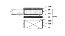
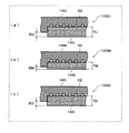
例えば、図1Aに示す如く、カソードガス拡散層114が、カソードセパレーター116の凹部に収納されるとともに、電解質膜111、カソード触媒層112、アノード触媒層113、カソードガス拡散層114、およびアノードガス拡散層115の積層体500の締結前に、凹部からその厚み方向に所定の大きさEではみ出して配設される構成が提案された。
For example, as shown in FIG. 1A, a cathode
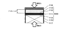
このとき、図1Bに示す如く、積層体500の締結時において、カソードガス拡散層114を、はみ出し量分、厚み方向に弾性変形する。
At this time, as shown in FIG. 1B, when the
ここで、この電気化学式水素ポンプの動作時に、積層体500のカソードガス拡散層114のガス圧が高圧になると、電解質膜111がガスを通さないので、アノードガス拡散層115、アノード触媒層113および電解質膜111に高圧がかかる。すると、アノードガス拡散層115、アノード触媒層113および電解質膜111のそれぞれが圧縮変形する。しかし、このとき、カソードガス拡散層114が、締結器による圧縮後の厚みΔTから圧縮前の厚みTに戻る方向に弾性変形することにより、カソード触媒層112とカソードガス拡散層114との間の接触を適切に維持できる。
Here, during the operation of the electrochemical hydrogen pump, if the gas pressure of the cathode
しかしながら、上述の通り、カソードのガス圧が高圧になると、カソードセパレーター116が、これに近接する図示しないエンドプレート側(外側)に膨らむように変形するので、カソードセパレーター116の凹部の底面とカソードガス拡散層114との間に隙間が生じやすくなる。すると、両者間の接触抵抗が増加する可能性がある。その結果、電圧印加器で印加する電圧が増加することにより、電気化学式水素ポンプの運転効率を低下させる恐れがある。
However, as described above, when the gas pressure of the cathode becomes high, the
そこで、発明者らは、カソードセパレーター116とカソードガス拡散層114との電気的接触を確保するには、カソードセパレーター116の変形量分を考慮して、カソードガス拡散層114のはみ出し量Eを更に大きくするという着想に到達し、以下の本開示の一態様に完成させた。
Therefore, the present inventors further consider the amount of deformation of the
なお、この問題は、上記の出願人の先行特許の例に限らず、凹部が設けられていないカソードセパレーターの平面上にカソードガス拡散層が設けられている形態においても、同様に発生する。 This problem is not limited to the example of the above-mentioned prior patent of the applicant, but also occurs in the case where the cathode gas diffusion layer is provided on the plane of the cathode separator where no recess is provided.
すなわち、本開示の第1態様の電気化学式水素ポンプは、
電解質膜、電解質膜の一方の主面上に設けられたアノード触媒層、電解質膜の他方の主面上に設けられたカソード触媒層、アノード触媒層上に設けられたアノードガス拡散層、アノードガス拡散層上に設けられたアノードセパレーター、カソード触媒層上に設けられたカソードガス拡散層、およびカソードガス拡散層上に設けられたカソードセパレーターを備える水素ポンプユニットと、
少なくとも3つ以上の積層された水素ポンプユニットの積層方向の両端上に設けられた第1の端板および第2の端板と、
第1の端板と第2の端板を締結して、水素ポンプユニットを積層方向に圧縮する締結器と、を備え、
少なくとも3つ以上の積層された水素ポンプユニットのカソードガス拡散層から流出するカソードガスが流れるカソードガス流路は連通されており、
締結器の締結によりカソードガス拡散層が圧縮される厚みの大きさは、積層された水素ポンプユニットの両端の少なくとも一方の端に位置する水素ポンプユニットのカソードガス拡散層の方が、積層された水素ポンプユニットの両端に位置しない水素ポンプユニットのカソードガス拡散層よりも大きい。
That is, the electrochemical hydrogen pump according to the first embodiment of the present disclosure includes:
Electrolyte membrane, anode catalyst layer provided on one main surface of electrolyte membrane, cathode catalyst layer provided on the other main surface of electrolyte membrane, anode gas diffusion layer provided on anode catalyst layer, anode gas An anode separator provided on the diffusion layer, a cathode gas diffusion layer provided on the cathode catalyst layer, and a hydrogen pump unit including a cathode separator provided on the cathode gas diffusion layer,
A first end plate and a second end plate provided on both ends in the stacking direction of at least three or more stacked hydrogen pump units;
A fastener for fastening the first end plate and the second end plate and compressing the hydrogen pump unit in the stacking direction;
A cathode gas flow path through which a cathode gas flowing from a cathode gas diffusion layer of at least three or more stacked hydrogen pump units flows is connected,
The size of the thickness in which the cathode gas diffusion layer is compressed by fastening the fastener is such that the cathode gas diffusion layer of the hydrogen pump unit located at at least one end of both ends of the stacked hydrogen pump unit is stacked. It is larger than the cathode gas diffusion layer of the hydrogen pump unit that is not located at both ends of the hydrogen pump unit.
かかる構成によると、本態様の電気化学式水素ポンプは、従来に比べて、水素ポンプユニットを構成する部材間の接触抵抗の増加を簡易かつ適切に抑制し得る。 According to such a configuration, the electrochemical hydrogen pump of the present embodiment can easily and appropriately suppress an increase in contact resistance between members constituting the hydrogen pump unit as compared with the related art.
具体的には、積層された水素ポンプユニットの両端の少なくとも一方の端に位置する水素ポンプユニットでは、カソードガス拡散層のガス圧が高圧になると、水素ポンプユニットのセパレーターは、端板側(外側)に膨らむように変形する。 Specifically, in the hydrogen pump unit located at at least one end of both ends of the stacked hydrogen pump unit, when the gas pressure of the cathode gas diffusion layer becomes high, the separator of the hydrogen pump unit is placed on the end plate side (outside). ).
例えば、カソードガス拡散層のガス圧が高圧になると、カソード端板に近接する水素ポンプユニットのカソードセパレーターは、カソード端板側(外側)に膨らむように変形する。すると、この水素ポンプユニットにおいて、カソードセパレーターとカソードガス拡散層との間に隙間が生じやすくなる。 For example, when the gas pressure of the cathode gas diffusion layer becomes high, the cathode separator of the hydrogen pump unit close to the cathode end plate is deformed so as to expand toward the cathode end plate (outside). Then, in this hydrogen pump unit, a gap is easily generated between the cathode separator and the cathode gas diffusion layer.
また、例えば、カソードガス拡散層のガス圧が高圧になると、アノード端板に近接する水素ポンプユニットのアノードセパレーターは、アノードガス拡散層から圧力を受けるので、アノード端板側(外側)に膨らむように変形する。すると、この水素ポンプユニットにおいて、カソードガス拡散層と電解質膜(カソード触媒層)との間に隙間が生じやすくなる。 Further, for example, when the gas pressure of the cathode gas diffusion layer becomes high, the anode separator of the hydrogen pump unit close to the anode end plate receives pressure from the anode gas diffusion layer, so that the anode separator swells toward the anode end plate (outside). Deform to. Then, in this hydrogen pump unit, a gap is easily generated between the cathode gas diffusion layer and the electrolyte membrane (cathode catalyst layer).
しかし、本態様の電気化学式水素ポンプは、積層された水素ポンプユニットの両端の少なくとも一方の端に位置する水素ポンプユニットのカソードガス拡散層は、積層された水素ポンプユニットの両端に位置しない水素ポンプユニット(以下、中間部の水素ポンプユニットと略す場合がある)のカソードガス拡散層に比べて、締結器の締結によりカソードガス拡散層が圧縮される厚みが大きい。 However, in the electrochemical hydrogen pump of this embodiment, the cathode gas diffusion layer of the hydrogen pump unit located at at least one end of both ends of the stacked hydrogen pump unit is a hydrogen pump not located at both ends of the stacked hydrogen pump unit. As compared with the cathode gas diffusion layer of the unit (hereinafter, may be abbreviated as an intermediate hydrogen pump unit), the thickness of the cathode gas diffusion layer compressed by fastening the fastener is larger.
よって、カソードセパレーターがカソード端板側(外側)に膨らむように変形しても、カソード端板に近接する水素ポンプユニットのカソードガス拡散層が、カソードセパレーターの変形に追従するように締結器による圧縮後の厚みから圧縮前の元の厚みに戻る方向に弾性変形することができる。これにより、本態様の電気化学式水素ポンプは、カソードセパレーターとカソードガス拡散層との間に隙間が生じる可能性を低減することができる。その結果、本態様の電気化学式水素ポンプは、上記の水素ポンプユニットにおいて、カソードセパレーターおよびカソードガス拡散層間の接触抵抗の増加を簡易かつ適切に抑制することができる。 Therefore, even if the cathode separator is deformed so as to expand toward the cathode end plate (outside), the cathode gas diffusion layer of the hydrogen pump unit close to the cathode end plate is compressed by the fastener so as to follow the deformation of the cathode separator. It can be elastically deformed in a direction from the later thickness to the original thickness before compression. Thereby, the electrochemical hydrogen pump of the present embodiment can reduce the possibility that a gap is generated between the cathode separator and the cathode gas diffusion layer. As a result, in the electrochemical hydrogen pump according to this aspect, in the above-described hydrogen pump unit, an increase in contact resistance between the cathode separator and the cathode gas diffusion layer can be easily and appropriately suppressed.
また、アノードセパレーターがアノード端板側(外側)に膨らむように変形しても、アノード端板に近接する水素ポンプユニットのカソードガス拡散層が、アノードセパレーターの変形に追従するように締結器による圧縮後の厚みから圧縮前の元の厚みに戻る方向に弾性変形することができる。これにより、本態様の電気化学式水素ポンプは、カソードガス拡散層と電解質膜との間に隙間が生じる可能性を低減することができる。その結果、本態様の電気化学式水素ポンプは、上記の水素ポンプユニットにおいて、カソードガス拡散層および電解質膜間の接触抵抗の増加を簡易かつ適切に抑制することができる。 Further, even if the anode separator is deformed so as to expand toward the anode end plate (outside), the cathode gas diffusion layer of the hydrogen pump unit close to the anode end plate is compressed by the fastener so as to follow the deformation of the anode separator. It can be elastically deformed in a direction from the later thickness to the original thickness before compression. Thereby, the electrochemical hydrogen pump of the present embodiment can reduce the possibility that a gap is generated between the cathode gas diffusion layer and the electrolyte membrane. As a result, in the electrochemical hydrogen pump according to this aspect, in the above-described hydrogen pump unit, an increase in contact resistance between the cathode gas diffusion layer and the electrolyte membrane can be easily and appropriately suppressed.
また、本態様の電気化学式水素ポンプでは、水素ポンプユニットのそれぞれのカソードガス拡散層から流出するカソードガスが流れるカソードガス流路は連通されている。よって、中間部の水素ポンプユニットでは、水素ポンプユニットの両隣の水素ポンプユニットの高圧の水素含有ガスによって、水素ポンプユニットを構成する部材の変形が抑制される。よって、中間部の水素ポンプユニットのカソードガス拡散層は、積層された水素ポンプユニットの両端の少なくとも一方の端に位置する水素ポンプユニットのカソードガス拡散層に比べて、締結器の締結によりカソードガス拡散層が圧縮される厚みが小さい場合でも、水素ポンプユニットを構成する部材間に隙間が生じにくい。つまり、中間部の水素ポンプユニットのカソードガス拡散層では、締結器による圧縮後の厚みから圧縮前の元の厚みに戻る方向への弾性変形量を、積層された水素ポンプユニットの両端の少なくとも一方の端に位置する水素ポンプユニットのカソードガス拡散層の弾性変形量に比べて小さくしても、水素ポンプユニットを構成する部材間に隙間が生じる可能性を低減することができる。 Further, in the electrochemical hydrogen pump of this embodiment, the cathode gas flow paths through which the cathode gas flowing out of the respective cathode gas diffusion layers of the hydrogen pump unit flow are connected. Therefore, in the hydrogen pump unit in the middle part, the deformation of the members constituting the hydrogen pump unit is suppressed by the high-pressure hydrogen-containing gas of the hydrogen pump units on both sides of the hydrogen pump unit. Therefore, the cathode gas diffusion layer of the hydrogen pump unit in the middle part is smaller than the cathode gas diffusion layer of the hydrogen pump unit located at at least one end of both ends of the stacked hydrogen pump unit by the fastening of the fastener. Even when the thickness of the diffusion layer to be compressed is small, a gap is unlikely to be formed between the members constituting the hydrogen pump unit. In other words, in the cathode gas diffusion layer of the hydrogen pump unit in the middle part, the amount of elastic deformation in the direction of returning from the thickness after compression by the fastener to the original thickness before compression is at least one of both ends of the stacked hydrogen pump unit Even if the amount is smaller than the amount of elastic deformation of the cathode gas diffusion layer of the hydrogen pump unit located at the end of the hydrogen pump unit, it is possible to reduce the possibility that a gap is formed between members constituting the hydrogen pump unit.
また、本態様の電気化学式水素ポンプでは、中間部の水素ポンプユニットのカソードガス拡散層の厚みを両端部の水素ポンプユニットのカソードガス拡散層の厚みと同じにした場合に比べ、中間部の水素ポンプユニットは、水素ポンプユニットの厚み方向の電気抵抗が小さくなる。従って、本態様の電気化学式水素ポンプは、中間部の水素ポンプユニットのカソードガス拡散層の厚みを両端部の水素ポンプユニットのカソードガス拡散層の厚みと同じにした場合に比べ、発熱量が小さくなる。また、弾性率が同じカソードガス拡散層を両端部と中間部の水素ポンプユニットに用いる場合、本態様の電気化学式水素ポンプでは、中間部の水素ポンプユニットは、両端部の水素ポンプユニットと比較してカソードガス拡散層が薄くなり、水素ポンプユニット自体も薄くなる。従って、本態様の電気化学式水素ポンプは、中間部の水素ポンプユニットのカソードガス拡散層の厚みを両端部の水素ポンプユニットのカソードガス拡散層の厚みと同じにした場合に比べ、電気化学式水素ポンプ全体の薄型化、軽量化をはかることができる。 Further, in the electrochemical hydrogen pump of the present embodiment, compared with the case where the thickness of the cathode gas diffusion layer of the hydrogen pump unit at the middle portion is made equal to the thickness of the cathode gas diffusion layers of the hydrogen pump units at both ends, the hydrogen at the middle portion is reduced. The electric resistance of the pump unit in the thickness direction of the hydrogen pump unit is reduced. Therefore, in the electrochemical hydrogen pump of this embodiment, the calorific value is smaller than that in the case where the thickness of the cathode gas diffusion layer of the hydrogen pump unit at the middle part is the same as the thickness of the cathode gas diffusion layer of the hydrogen pump units at both ends. Become. Further, when the cathode gas diffusion layers having the same elastic modulus are used for the hydrogen pump units at both ends and the intermediate portion, in the electrochemical hydrogen pump of this embodiment, the hydrogen pump unit at the intermediate portion is compared with the hydrogen pump units at both ends. As a result, the cathode gas diffusion layer becomes thinner, and the hydrogen pump unit itself becomes thinner. Therefore, the electrochemical hydrogen pump of the present embodiment is different from the electrochemical hydrogen pump in that the thickness of the cathode gas diffusion layer of the hydrogen pump unit in the middle part is the same as the thickness of the cathode gas diffusion layers of the hydrogen pump units at both ends. The overall thickness and weight can be reduced.
以上により、本態様の電気化学式水素ポンプは、中間部の水素ポンプユニットを構成する部材間の接触抵抗の増加を簡易かつ適切に抑制することができる。また、本態様の電気化学式水素ポンプは、電気抵抗の低減、薄型化、軽量化などが可能となる。 As described above, the electrochemical hydrogen pump of the present embodiment can easily and appropriately suppress an increase in contact resistance between members constituting the hydrogen pump unit in the intermediate portion. Further, the electrochemical hydrogen pump of this embodiment can reduce electric resistance, reduce the thickness, reduce the weight, and the like.
本開示の第2態様の電気化学式水素ポンプは、第1態様の電気化学式水素ポンプであって、締結器による締結前において、積層された水素ポンプユニットの両端の少なくとも一方の端に位置する水素ポンプユニットのカソードガス拡散層の厚みが、積層された水素ポンプユニットの両端に位置しない水素ポンプユニットのカソードガス拡散層の厚みよりも大きくてもよい。 An electrochemical hydrogen pump according to a second aspect of the present disclosure is the electrochemical hydrogen pump according to the first aspect, wherein the hydrogen pump is located at at least one end of both ends of the stacked hydrogen pump unit before fastening by the fastener. The thickness of the cathode gas diffusion layer of the unit may be larger than the thickness of the cathode gas diffusion layer of the hydrogen pump unit that is not located at both ends of the stacked hydrogen pump unit.
本開示の第3態様の電気化学式水素ポンプは、第1態様の電気化学式水素ポンプであって、カソードセパレーターは、カソードガス拡散層を設置する凹部が設けられ、締結器による締結前において、積層された水素ポンプユニットの両端の少なくとも一方の端に位置する水素ポンプユニットのカソードセパレーターの凹部から突出するカソードガス拡散層の厚みは、積層された水素ポンプユニットの両端に位置しない水素ポンプユニットのカソードセパレーターの凹部から突出するカソードガス拡散層の厚みよりも大きくてもよい。 An electrochemical hydrogen pump according to a third aspect of the present disclosure is the electrochemical hydrogen pump according to the first aspect, wherein the cathode separator is provided with a concave portion for installing a cathode gas diffusion layer, and is stacked before fastening by a fastener. The thickness of the cathode gas diffusion layer protruding from the concave portion of the cathode separator of the hydrogen pump unit located at at least one end of both ends of the hydrogen pump unit, the cathode separator of the hydrogen pump unit not located at both ends of the stacked hydrogen pump unit May be larger than the thickness of the cathode gas diffusion layer protruding from the concave portion.
以上の構成によると、本態様の電気化学式水素ポンプでは、積層された水素ポンプユニットの両端の少なくとも一方の端に位置する水素ポンプユニットのカソードガス拡散層が締結器の締結によって圧縮される厚みを、適切に、中間部の水素ポンプユニットのカソードガス拡散層が締結器の締結によって圧縮される厚みよりも大きくすることができる。 According to the above configuration, in the electrochemical hydrogen pump of the present embodiment, the thickness of the cathode gas diffusion layer of the hydrogen pump unit located at at least one end of both ends of the stacked hydrogen pump unit is compressed by fastening the fastener. The thickness of the cathode gas diffusion layer of the middle hydrogen pump unit can be appropriately increased by compression of the fastener.
本開示の第4態様の電気化学式水素ポンプは、第3態様の電気化学式水素ポンプであって、積層された水素ポンプユニットの両端の少なくとも一方の端に位置する水素ポンプユニットのカソードセパレーターの凹部の深さは、積層された水素ポンプユニットの両端に位置しない水素ポンプユニットのカソードセパレーターの凹部の深さよりも浅くてもよい。 An electrochemical hydrogen pump according to a fourth aspect of the present disclosure is the electrochemical hydrogen pump according to the third aspect, wherein the concave part of the cathode separator of the hydrogen pump unit is located at at least one end of both ends of the stacked hydrogen pump unit. The depth may be smaller than the depth of the concave portion of the cathode separator of the hydrogen pump unit that is not located at both ends of the stacked hydrogen pump unit.
かかる構成によると、本態様の電気化学式水素ポンプは、水素ポンプユニットのそれぞれのカソードガス拡散層の厚みが同じ場合でも、積層された水素ポンプユニットの両端の少なくとも一方の端に位置する水素ポンプユニットのカソードガス拡散層が締結器の締結によって圧縮される厚みを、適切に、中間部の水素ポンプユニットのカソードガス拡散層が締結器の締結によって圧縮される厚みよりも大きくすることができる。 According to this configuration, the electrochemical hydrogen pump according to the present embodiment has the hydrogen pump unit located at at least one end of both ends of the stacked hydrogen pump unit even when the thickness of each cathode gas diffusion layer of the hydrogen pump unit is the same. The thickness in which the cathode gas diffusion layer of the hydrogen pump unit in the middle portion is compressed by the fastening of the fastener can be appropriately larger than the thickness of the cathode gas diffusion layer of the middle hydrogen pump unit that is compressed by the fastening of the fastener.
本開示の第5態様の電気化学式水素ポンプは、第1態様から第4態様のいずれか一つの電気化学式水素ポンプにおいて、積層された水素ポンプユニットの両端の少なくとも一方の端に位置する水素ポンプユニットのカソードガス拡散層のカソードセパレーター側の主面には、凸部が設けられていてもよい。 An electrochemical hydrogen pump according to a fifth aspect of the present disclosure is the electrochemical hydrogen pump according to any one of the first to fourth aspects, wherein the hydrogen pump unit is located at at least one end of both ends of the stacked hydrogen pump unit. A projection may be provided on the main surface of the cathode gas diffusion layer on the cathode separator side.
上記のとおり、カソード端板に近接する水素ポンプユニットのカソードガス拡散層のガス圧が高圧になると、この水素ポンプユニットのカソードセパレーターは、カソード端板側(外側)に膨らむように変形する。すると、カソードガス拡散層側のカソードセパレーターの主面は、高圧の水素含有ガスによって中央部の変形量が端部の変形量に比べて大きくなるように変形する。つまり、カソードセパレーターの主面が、高圧の水素含有ガスによってドーム状に変形する。 As described above, when the gas pressure of the cathode gas diffusion layer of the hydrogen pump unit close to the cathode end plate becomes high, the cathode separator of the hydrogen pump unit is deformed so as to expand toward the cathode end plate (outside). Then, the main surface of the cathode separator on the side of the cathode gas diffusion layer is deformed by the high-pressure hydrogen-containing gas such that the amount of deformation at the center is larger than the amount of deformation at the ends. That is, the main surface of the cathode separator is deformed into a dome shape by the high-pressure hydrogen-containing gas.
なお、かかる現象は、カソードガス拡散層を設置する凹部が設けているカソードセパレーター、および、このような凹部が設けられていないカソードセパレーターのいずれの形態においても発生する。 Such a phenomenon occurs in both the cathode separator provided with the concave portion in which the cathode gas diffusion layer is provided and the cathode separator not provided with such a concave portion.
そこで、本態様の電気化学式水素ポンプは、カソードガス拡散層のカソードセパレーター側の主面に凸部を設けることで、カソードガス拡散層の主面が、高圧の水素含有ガスによってドーム状に変形するカソードセパレーターの主面と密着しやすいように構成されている。よって、本態様の電気化学式水素ポンプは、カソードガス拡散層の主面に凸部を設けない場合に比べて、カソードセパレーターとカソードガス拡散層との間に隙間が生じる可能性を低減することができる。 Therefore, in the electrochemical hydrogen pump of the present embodiment, by providing a convex portion on the main surface of the cathode gas diffusion layer on the cathode separator side, the main surface of the cathode gas diffusion layer is deformed into a dome shape by the high-pressure hydrogen-containing gas. It is configured so that it can easily adhere to the main surface of the cathode separator. Therefore, the electrochemical hydrogen pump of the present embodiment can reduce the possibility that a gap is generated between the cathode separator and the cathode gas diffusion layer, as compared with the case where no convex portion is provided on the main surface of the cathode gas diffusion layer. it can.
ところで、カソードガス拡散層の厚み方向の電気抵抗は、カソードガス拡散層の厚みに比例する。また、積層された水素ポンプユニットの両端の少なくとも一方の端に位置する水素ポンプユニットでは、中間部の水素ポンプユニットに比べて、締結器の締結により圧縮される厚みが大きい。よって、積層された水素ポンプユニットの両端の少なくとも一方の端に位置する水素ポンプユニットのカソードガス拡散層の厚み方向の電気抵抗は、中間部の水素ポンプユニットの厚み方向の電気抵抗よりも締結器による締結に伴って低下しやすい。 By the way, the electric resistance in the thickness direction of the cathode gas diffusion layer is proportional to the thickness of the cathode gas diffusion layer. Further, the thickness of the hydrogen pump unit located at at least one end of both ends of the stacked hydrogen pump units is larger than that of the hydrogen pump unit in the middle part, which is compressed by fastening the fastener. Therefore, the electrical resistance in the thickness direction of the cathode gas diffusion layer of the hydrogen pump unit located at at least one end of both ends of the stacked hydrogen pump unit is smaller than the electrical resistance in the thickness direction of the hydrogen pump unit in the middle part. It tends to decrease with the fastening.
そこで、本開示の第6態様の電気化学式水素ポンプは、第1態様から第5態様のいずれか一つの電気化学式水素ポンプであって、締結器による締結前において、積層された水素ポンプユニットの両端の少なくとも一方の端に位置する水素ポンプユニットのカソードガス拡散層の厚み方向の電気抵抗が、積層された水素ポンプユニットの両端に位置しない水素ポンプユニットのカソードガス拡散層の厚み方向の電気抵抗よりも大きくてもよい。 Therefore, the electrochemical hydrogen pump according to the sixth aspect of the present disclosure is the electrochemical hydrogen pump according to any one of the first aspect to the fifth aspect, wherein both ends of the stacked hydrogen pump units before the fastening by the fastener are performed. The electrical resistance in the thickness direction of the cathode gas diffusion layer of the hydrogen pump unit located at at least one end of the hydrogen pump unit is smaller than the electrical resistance in the thickness direction of the cathode gas diffusion layer of the hydrogen pump unit not located at both ends of the stacked hydrogen pump unit. May also be large.
かかる構成によると、本態様の電気化学式水素ポンプは、締結器による締結時において、水素ポンプユニットのそれぞれのカソードガス拡散層の厚み方向の電気抵抗を均一化させやすくすることができる。 According to this configuration, in the electrochemical hydrogen pump of this aspect, when fastening with the fastener, the electrical resistance in the thickness direction of each cathode gas diffusion layer of the hydrogen pump unit can be easily made uniform.
つまり、本態様の電気化学式水素ポンプは、締結器による締結に伴って生じる水素ポンプユニットのそれぞれのカソードガス拡散層の厚み方向の電気抵抗低下のバラツキを、締結器による締結前における水素ポンプユニットのそれぞれのカソードガス拡散層の厚み方向の電気抵抗の不均一性で相殺させることができる。よって、本態様の電気化学式水素ポンプは、締結器による締結前において、水素ポンプユニットのそれぞれのカソードガス拡散層の厚み方向の電気抵抗が均等である場合に比べて、締結器による締結時における水素ポンプユニットのそれぞれのカソードガス拡散層の厚み方向の電気抵抗が均一化し得る。 In other words, the electrochemical hydrogen pump of the present embodiment reduces the variation in the electrical resistance decrease in the thickness direction of each of the cathode gas diffusion layers of the hydrogen pump unit caused by the fastening by the fastener, and the variation of the hydrogen pump unit before fastening by the fastener. This can be offset by the non-uniformity of the electric resistance in the thickness direction of each cathode gas diffusion layer. Therefore, the electrochemical hydrogen pump of the present embodiment has a higher hydrogen resistance at the time of fastening by the fastener than before the fastening by the fastener, as compared with the case where the electrical resistance in the thickness direction of each cathode gas diffusion layer of the hydrogen pump unit is uniform. The electric resistance in the thickness direction of each cathode gas diffusion layer of the pump unit can be made uniform.
本開示の第7態様の電気化学式水素ポンプは、第1態様から第6態様のいずれか一つの電気化学式水素ポンプにおいて、第1の端板と、積層された水素ポンプユニットのうち第1の端板側の端に位置する水素ポンプユニットとの間に、カソードガス流路から排出された水素含有ガスを貯える第一空間が設けられ、締結器の締結によりカソードガス拡散層が圧縮される厚みの大きさは、積層された水素ポンプユニットのうち第2の端板側の端に位置する水素ポンプユニットのカソードガス拡散層の方が、積層された水素ポンプユニットのうち第1の端板側の端に位置する水素ポンプユニットのカソードガス拡散層よりも大きくてもよい。 An electrochemical hydrogen pump according to a seventh aspect of the present disclosure is the electrochemical hydrogen pump according to any one of the first to sixth aspects, wherein the first end plate and the first end of the stacked hydrogen pump units are provided. A first space for storing the hydrogen-containing gas discharged from the cathode gas flow path is provided between the hydrogen pump unit and the hydrogen pump unit located at the plate-side end, and the cathode gas diffusion layer is compressed by fastening the fastener. The size is such that the cathode gas diffusion layer of the hydrogen pump unit located at the end on the second end plate side of the stacked hydrogen pump units is closer to the first end plate side of the stacked hydrogen pump units. It may be larger than the cathode gas diffusion layer of the hydrogen pump unit located at the end.
積層された水素ポンプユニットのうち第1の端板側の端に位置する水素ポンプユニット(以下、第1の端板側の水素ポンプユニット)と第1の端板との間に設けられた第一空間の水素含有ガス圧は、水素ポンプユニットのカソード内の水素含有ガス圧とほぼ同等の高圧である。すると、第一空間内の水素含有ガスによって、第1の端板側の水素ポンプユニットのセパレーターに付与される荷重は、カソード内の水素含有ガス圧に起因するセパレーターの変形(たわみ)を抑えるように作用する。 Among the stacked hydrogen pump units, a hydrogen pump unit located at an end on the first end plate side (hereinafter, a hydrogen pump unit on the first end plate side) and a first end plate provided between the first end plate The hydrogen-containing gas pressure in one space is a high pressure substantially equal to the hydrogen-containing gas pressure in the cathode of the hydrogen pump unit. Then, the load applied to the separator of the hydrogen pump unit on the first end plate side by the hydrogen-containing gas in the first space suppresses the deformation (deflection) of the separator due to the hydrogen-containing gas pressure in the cathode. Act on.
これに対して、積層された水素ポンプユニットのうち第2の端板側の端に位置する水素ポンプユニット(以下、第2の端板側の水素ポンプユニット)と第2の端板との間には、水素ポンプユニットのカソード内の水素含有ガス圧とほぼ同等の高圧の水素含有ガスを貯える空間が存在しない。このため、第2の端板側の水素ポンプユニットのセパレーターには、カソード内の水素含有ガス圧に起因するセパレーターの変形(たわみ)を抑えるような荷重が付与されない。つまり、第2の端板側の水素ポンプユニットでは、第1の端板側の水素ポンプユニットに比べて、水素ポンプユニットのカソード内の水素含有ガス圧によって、水素ポンプユニットを構成する部材間に隙間が生じやすくなる。 On the other hand, between the hydrogen pump unit located at the end on the second end plate side (hereinafter, the hydrogen pump unit on the second end plate side) of the stacked hydrogen pump units and the second end plate Does not have a space for storing a high-pressure hydrogen-containing gas substantially equal to the hydrogen-containing gas pressure in the cathode of the hydrogen pump unit. Therefore, no load is applied to the separator of the hydrogen pump unit on the second end plate side so as to suppress deformation (deflection) of the separator due to the pressure of the hydrogen-containing gas in the cathode. In other words, in the hydrogen pump unit on the second end plate side, the hydrogen-containing gas pressure in the cathode of the hydrogen pump unit makes the hydrogen pump unit between the members constituting the hydrogen pump unit different from the hydrogen pump unit on the first end plate side. Gaps tend to form.
そこで、本態様の電気化学式水素ポンプは、締結器の締結によりカソードガス拡散層が圧縮される厚みの大きさを、第2の端板側の水素ポンプユニットのカソードガス拡散層の方を、第1の端板側の水素ポンプユニットのカソードガス拡散層よりも大きくすることで、第2の端板側の水素ポンプユニットを構成する部材間に隙間が生じる可能性を低減することができる。 Therefore, the electrochemical hydrogen pump according to the present embodiment is configured such that the thickness of the cathode gas diffusion layer compressed by the fastening of the fastener is equal to the thickness of the cathode gas diffusion layer of the hydrogen pump unit on the second end plate side. By making it larger than the cathode gas diffusion layer of the hydrogen pump unit on the first end plate side, it is possible to reduce the possibility that a gap is formed between members constituting the hydrogen pump unit on the second end plate side.
本開示の第8態様の電気化学式水素ポンプは、第1態様から第6態様のいずれか一つの電気化学式水素ポンプにおいて、第2の端板と、積層された水素ポンプユニットのうち第2の端板側の端に位置する水素ポンプユニットとの間に、カソードガス流路から排出された水素含有ガスを貯える第二空間が設けられ、締結器の締結によりカソードガス拡散層が圧縮される厚みの大きさは、積層された水素ポンプユニットのうち第1の端板側に位置する水素ポンプユニットのカソードガス拡散層の方が、積層された水素ポンプユニットのうち第2の端板側の端に位置する水素ポンプユニットのカソードガス拡散層よりも大きくてもよい。 An electrochemical hydrogen pump according to an eighth aspect of the present disclosure is the electrochemical hydrogen pump according to any one of the first aspect to the sixth aspect, wherein the second end plate and the second end of the stacked hydrogen pump units are provided. A second space for storing the hydrogen-containing gas discharged from the cathode gas flow path is provided between the hydrogen pump unit and the hydrogen pump unit located at the plate side end, and the cathode gas diffusion layer is compressed by fastening the fastener. The size is such that the cathode gas diffusion layer of the hydrogen pump unit located on the first end plate side of the stacked hydrogen pump units is closer to the end on the second end plate side of the stacked hydrogen pump units. It may be larger than the cathode gas diffusion layer of the located hydrogen pump unit.
第2の端板側の水素ポンプユニットと第2の端板との間に設けられた第二空間の水素含有ガス圧は、水素ポンプユニットのカソード内の水素含有ガス圧とほぼ同等の高圧である。すると、第二空間内の水素含有ガスによって、第2の端板側の水素ポンプユニットのセパレーターに付与される荷重は、カソード内の水素含有ガス圧に起因するセパレーターの変形(たわみ)を抑えるように作用する。 The hydrogen-containing gas pressure in the second space provided between the hydrogen pump unit on the second end plate side and the second end plate is a high pressure substantially equal to the hydrogen-containing gas pressure in the cathode of the hydrogen pump unit. is there. Then, the load applied to the separator of the hydrogen pump unit on the second end plate side by the hydrogen-containing gas in the second space suppresses the deformation (deflection) of the separator due to the hydrogen-containing gas pressure in the cathode. Act on.
これに対して、第1の端板側の水素ポンプユニットと第1の端板との間には、水素ポンプユニットのカソード内の水素含有ガス圧とほぼ同等の高圧の水素含有ガスを貯える空間が存在しない。このため、第1の端板側の水素ポンプユニットのセパレーターには、カソード内の水素含有ガス圧に起因するセパレーターの変形(たわみ)を抑えるような荷重が付与されない。つまり、第1の端板側の水素ポンプユニットでは、第2の端板側の水素ポンプユニットに比べて、水素ポンプユニットのカソード内の水素含有ガス圧によって、水素ポンプユニットを構成する部材間に隙間が生じやすくなる。 On the other hand, between the hydrogen pump unit on the first end plate side and the first end plate, a space for storing a high-pressure hydrogen-containing gas substantially equal to the hydrogen-containing gas pressure in the cathode of the hydrogen pump unit. Does not exist. Therefore, no load is applied to the separator of the hydrogen pump unit on the first end plate side so as to suppress deformation (deflection) of the separator due to the pressure of the hydrogen-containing gas in the cathode. That is, in the hydrogen pump unit on the first end plate side, the hydrogen-containing gas pressure in the cathode of the hydrogen pump unit is higher than the hydrogen pump unit on the second end plate side. Gaps tend to form.
そこで、本態様の電気化学式水素ポンプは、締結器の締結によりカソードガス拡散層が圧縮される厚みの大きさを、第1の端板側の水素ポンプユニットのカソードガス拡散層の方を、第2の端板側の水素ポンプユニットのカソードガス拡散層よりも大きくすることで、第1の端板側の水素ポンプユニットを構成する部材間に隙間が生じる可能性を低減することができる。 Therefore, in the electrochemical hydrogen pump of this aspect, the cathode gas diffusion layer of the hydrogen pump unit on the first end plate side has the same thickness as the thickness of the cathode gas diffusion layer compressed by the fastening of the fastener. By making it larger than the cathode gas diffusion layer of the hydrogen pump unit on the second end plate side, it is possible to reduce the possibility that a gap is formed between members constituting the hydrogen pump unit on the first end plate side.
以下、添付図面を参照しながら、本開示の実施形態について説明する。なお、以下で説明する実施形態は、いずれも上記の各態様の一例を示すものである。よって、以下で示される形状、材料、構成要素、および、構成要素の配置位置および接続形態などは、あくまで一例であり、請求項に記載されていない限り、上記の各態様を限定するものではない。また、以下の構成要素のうち、上記の各態様の最上位概念を示す独立請求項に記載されていない構成要素については、任意の構成要素として説明される。また、図面において、同じ符号が付いたものは、説明を省略する場合がある。図面は理解しやすくするために、それぞれの構成要素を模式的に示したもので、形状および寸法比などについては正確な表示ではない場合がある。 Hereinafter, embodiments of the present disclosure will be described with reference to the accompanying drawings. Each of the embodiments described below is an example of each of the above aspects. Therefore, the shapes, materials, components, and the arrangement positions and connection forms of the components shown below are merely examples, and do not limit the above embodiments unless otherwise described in the claims. . In addition, among the following components, components not described in the independent claims that indicate the highest concept of each aspect described above are described as arbitrary components. Also, in the drawings, the description of the same reference numeral may be omitted. In the drawings, each component is schematically shown for easy understanding, and shapes and dimensional ratios may not be accurately displayed.
(第1実施形態)
[装置構成]
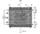
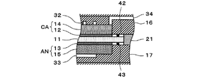
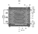
図2Aおよび図3Aは、第1実施形態の電気化学式水素ポンプの一例を示す図である。図2Bは、図2AのB部の拡大図である。図3Bは、図3AのB部の拡大図である。
(1st Embodiment)
[Device configuration]
2A and 3A are diagrams illustrating an example of the electrochemical hydrogen pump according to the first embodiment. FIG. 2B is an enlarged view of a portion B in FIG. 2A. FIG. 3B is an enlarged view of a portion B in FIG. 3A.
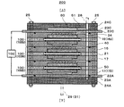
図2Aには、平面視において電気化学式水素ポンプ200の中心と、カソードガス導出マニホールド50の中心と、を通過する直線を含む電気化学式水素ポンプ200の垂直断面が示されている。また、図3Aには、平面視において電気化学式水素ポンプ200の中心と、アノードガス導入マニホールド27の中心と、アノードガス導出マニホールド30の中心と、を通過する直線を含む電気化学式水素ポンプ200の垂直断面が示されている。
FIG. 2A shows a vertical cross section of the
なお、図2Aおよび図3Aでは、同図の如く、「上」および「下」が示されている(図7および図8においても同じ)。但し、これらの図中の「上」および「下」は、あくまで、以下の説明の便宜上、付されたものであり、電気化学式水素ポンプ200は、重力が作用する方向に対してどのような向きに置かれていても構わない。
2A and 3A, “upper” and “lower” are shown as in FIG. 2 (the same applies to FIGS. 7 and 8). However, “upper” and “lower” in these figures are given only for convenience of the following description, and the
図2Aおよび図3Bに示す例では、電気化学式水素ポンプ200は、少なくとも3つ以上の水素ポンプユニット100を備える。
In the example shown in FIGS. 2A and 3B, the
なお、図2Aおよび図3Bの電気化学式水素ポンプ200には、3つの水素ポンプユニット100U、100M、100Dが積層されているが、水素ポンプユニット100の個数はこれに限定されない。つまり、水素ポンプユニット100の個数は、電気化学式水素ポンプ200が昇圧する水素量などの運転条件をもとに適宜の数に設定することができる。
Although three
水素ポンプユニット100U、100M、100Dはそれぞれ、電解質膜11と、アノードANと、カソードCAと、カソードセパレーター16と、アノードセパレーター17と、絶縁体21と、を備える。
Each of the
アノードANは、電解質膜11の一方の主面上に設けられている。アノードANは、アノード触媒層13と、アノードガス拡散層15とを含む電極である。なお、平面視において、アノード触媒層13の周囲を囲むように環状のシール部材43が設けられ、アノード触媒層13が、シール部材43で適切にシールされている。
The anode AN is provided on one main surface of the
カソードCAは、電解質膜11の他方の主面上に設けられている。カソードCAは、カソード触媒層12と、カソードガス拡散層14とを含む電極である。なお、平面視において、カソード触媒層12の周囲を囲むように環状のシール部材42が設けられ、カソード触媒層12が、シール部材42で適切にシールされている。
Cathode CA is provided on the other main surface of
以上により、電解質膜11は、アノード触媒層13およびカソード触媒層12のそれぞれと接触するようにして、アノードANとカソードCAとによって挟持されている。なお、カソードCA、電解質膜11およびアノードANの積層体を膜−電極接合体(以下、MEA:Membrane Electrode Assembly)という。
As described above, the
電解質膜11は、プロトン伝導性を備える。電解質膜11は、プロトン伝導性を備えていれば、どのような構成であってもよい。例えば、電解質膜11として、フッ素系高分子電解質膜、炭化水素系高分子電解質膜を挙げることができるが、これらに限定されない。具体的には、例えば、電解質膜11として、Nafion(登録商標、デュポン社製)、Aciplex(登録商標、旭化成株式会社製)などを用いることができる。
The
アノード触媒層13は、電解質膜11の一方の主面上に設けられている。アノード触媒層13は、触媒金属として、例えば、白金を含むが、これに限定されない。
The
カソード触媒層12は、電解質膜11の他方の主面上に設けられている。カソード触媒層12は、触媒金属として、例えば、白金を含むが、これに限定されない。
カソード触媒層12およびアノード触媒層13の触媒担体としては、例えば、カーボンブラック、黒鉛などの炭素粉体、導電性の酸化物粉体などが挙げられるが、これらに限定されない。
Examples of the catalyst carrier of the
なお、カソード触媒層12およびアノード触媒層13では、触媒金属の微粒子が、触媒担体に高分散に担持されている。また、これらのカソード触媒層12およびアノード触媒層13中には、電極反応場を大きくするために、水素イオン伝導性のイオノマー成分を加えることが一般的である。
In the
アノードガス拡散層15は、アノード触媒層13上に設けられている。アノードガス拡散層15は、多孔性材料で構成され、導電性およびガス拡散性を備える。また、アノードガス拡散層15は、電気化学式水素ポンプ200の動作時にカソードCAおよびアノードAN間の差圧で発生する構成部材の変位、変形を抑制可能な高剛性であることが望ましい。よって、アノードガス拡散層15の弾性率は、カソードガス拡散層14の弾性率よりも高い。
The anode
アノードガス拡散層15の基材として、例えば、チタン、チタン合金、ステンレススチールなどを素材とする金属繊維の焼結体、これらを素材とする金属粉体の焼結体、エキスパンドメタル、金属メッシュ、パンチングメタルなどを用いることができる。
As a base material of the anode
カソードガス拡散層14は、カソード触媒層12上に設けられている。カソードガス拡散層14は、多孔性材料で構成され、導電性およびガス拡散性を備える。また、カソードガス拡散層14は、電気化学式水素ポンプ200の動作時にカソードおよびアノード間の差圧で発生する構成部材の変位、変形に適切に追従するような弾性を備える方が望ましい。よって、カソードガス拡散層14の弾性率は、アノードガス拡散層15の弾性率よりも低い。
The cathode
カソードガス拡散層14の基材として、例えば、チタン、チタン合金、ステンレススチールなどを素材とする金属繊維の焼結体、これらを素材とする金属粉末の焼結体などを用いることができる。また、カソードガス拡散層14の基材に、カーボンペーパー、カーボンクロス、カーボンフェルトなどの多孔性の炭素材料を用いることもできる。更に、カーボンブラックとPTFEなどのエラストマーを混錬、圧延した多孔性のシート材料などを用いることもできる。
As the base material of the cathode
アノードセパレーター17は、アノードガス拡散層15上に設けられた部材である。また、カソードセパレーター16は、カソードガス拡散層14上に設けられた部材である。具体的には、カソードセパレーター16およびアノードセパレーター17のそれぞれの中央部には、カソードガス拡散層14およびアノードガス拡散層15のそれぞれを設置する凹部が設けられている。つまり、これらの凹部のそれぞれに、カソードガス拡散層14およびアノードガス拡散層15がそれぞれ収容されている。
The
このようにして、カソードセパレーター16およびアノードセパレーター17で上記のMEAを挟むことにより、水素ポンプユニット100が形成されている。
Thus, the
カソードガス拡散層14と接触するカソードセパレーター16の主面には、平面視において、例えば、複数のU字状の折り返す部分と複数の直線部分とを含むサーペンタイン状のカソードガス流路32が設けられている。そして、カソードガス流路32の直線部分は、図2Aの紙面に垂直な方向(図3Aの紙面に平行な方向)に延伸している。但し、このようなカソードガス流路32は、例示であって、本例に限定されない。例えば、カソードガス流路は、複数の直線状の流路により構成されていてもよい。
On the main surface of the
アノードガス拡散層15と接触するアノードセパレーター17の主面には、平面視において、例えば、複数のU字状の折り返す部分と複数の直線部分とを含むサーペンタイン状のアノードガス流路33が設けられている。そして、アノードガス流路33の直線部分は、図3Aの紙面に垂直な方向(図2Aの紙面に平行な方向)に延伸している。但し、このようなアノードガス流路33は、例示であって、本例に限定されない。例えば、アノードガス流路は、複数の直線状の流路により構成されていてもよい。
On the main surface of the
また、導電性のカソードセパレーター16およびアノードセパレーター17の間には、MEAの周囲を囲むように設けられた環状かつ平板状の絶縁体21が挟み込まれている。これにより、カソードセパレーター16およびアノードセパレーター17の短絡が防止されている。
Further, between the
ここで、図2Aおよび図3Aに示すように、電気化学式水素ポンプ200は、水素ポンプユニット100の積層方向の両端上に設けられた第1の端板(以下、カソード端板24C)および第2の端板(以下、アノード端板24A)と、カソード端板24Cとアノード端板24Aを締結して、水素ポンプユニット100を積層方向に圧縮する締結器25と、を備える。
Here, as shown in FIGS. 2A and 3A, the
つまり、アノード端板24Aは、水素ポンプユニット100が積層された積層方向において、一方の端に位置するアノードセパレーター17D上に設けられた部材である。また、カソード端板24Cは、水素ポンプユニット100が積層された積層方向において、他方の端に位置するカソードセパレーター16U上に設けられた部材である。
That is, the
締結器25は、カソード端板24Cとアノード端板24Aを締結して、水素ポンプユニット100を積層方向に圧縮することができれば、どのような構成であってもよい。
The
例えば、締結器25として、ボルトおよび皿ばね付きナットなどを挙げることができる。このとき、締結器25のボルトは、アノード端板24Aおよびカソード端板24Cのみを貫通するように構成してもよいが、電気化学式水素ポンプ200では、かかるボルトは、水素ポンプユニット100U、100M、100Dをそれぞれ構成する部材、カソード給電板22C、カソード絶縁板23C、アノード給電板22A、アノード絶縁板23A、アノード端板24Aおよびカソード端板24Cを貫通している。そして、上記の積層方向において他方の端に位置するカソードセパレーター16Uの端面、および、上記の積層方向において一方の端に位置するアノードセパレーター17Dの端面をそれぞれ、カソード給電板22Cとカソード絶縁板23Cおよびアノード給電板22Aとアノード絶縁板23Aのそれぞれを介して、カソード端板24Cおよびアノード端板24Aのそれぞれで挟むようにして、締結器25により水素ポンプユニット100に所望の締結圧が付与されている。
For example, the
以上により、本実施形態の電気化学式水素ポンプ200では、複数段(図2Aおよび図3Aでは、3つ)の水素ポンプユニット100が、上記の積層方向において、締結器25の締結圧により積層状態で適切に保持されるとともに、電気化学式水素ポンプ200を構成する部材を締結器25のボルトが貫通しているので、これらの部材の面内方向における移動を適切に抑えることができる。
As described above, in the
ここで、本実施形態の電気化学式水素ポンプ200では、水素ポンプユニット100U、100M、100Dのそれぞれのカソードガス拡散層14から流出するカソードガスが流れるカソードガス流路32は連通されている。以下、図面を参照しながら、カソードガス流路32のそれぞれが連通する構成について説明する。
Here, in the
まず、図2Aに示すように、カソードガス導出マニホールド50は、水素ポンプユニット100U、100M、100Dのそれぞれの部材およびカソード端板24Cに設けられた貫通孔およびアノード端板24Aに設けられた非貫通孔の連なりによって構成されている。また、カソード端板24Cには、カソードガス導出経路26が設けられている。カソードガス導出経路26は、カソードCAから排出される水素含有ガスが流通する配管で構成されていてもよい。そして、カソードガス導出経路26は、上記のカソードガス導出マニホールド50と連通している。
First, as shown in FIG. 2A, the cathode
更に、カソードガス導出マニホールド50は、水素ポンプユニット100U、100M、100Dのそれぞれのカソードガス流路32の一方の端部と、カソードガス通過経路34のそれぞれを介して連通している。これにより、水素ポンプユニット100U、100M、100Dのそれぞれのカソードガス流路32およびカソードガス通過経路34を通過した水素含有ガスが、カソードガス導出マニホールド50で合流される。そして、合流された水素含有ガスがカソードガス導出経路26に導かれる。
Further, the cathode
このようにして、水素ポンプユニット100U、100M、100Dのそれぞれのカソードガス流路32は、水素ポンプユニット100U、100M、100Dのそれぞれのカソードガス通過経路34およびカソードガス導出マニホールド50を介して連通している。
In this way, the respective
カソードセパレーター16およびアノードセパレーター17の間、カソードセパレーター16Uおよびカソード給電板22Cの間、アノードセパレーター17Dおよびアノード給電板22Aの間には、平面視において、カソードガス導出マニホールド50を囲むように、Oリングなどの環状のシール部材40が設けられ、カソードガス導出マニホールド50が、このシール部材40で適切にシールされている。
An O-ring is provided between the
図3Aに示す如く、アノード端板24Aには、アノードガス導入経路29が設けられている。アノードガス導入経路29は、アノードANに供給される水素含有ガスが流通する配管で構成されていてもよい。そして、アノードガス導入経路29は、筒状のアノードガス導入マニホールド27に連通している。なお、アノードガス導入マニホールド27は、水素ポンプユニット100U、100M、100Dのそれぞれの部材およびアノード端板24Aに設けられた貫通孔の連なりによって構成されている。
As shown in FIG. 3A, an anode
また、アノードガス導入マニホールド27は、水素ポンプユニット100U、100M、100Dのそれぞれのアノードガス流路33の一方の端部と、第1アノードガス通過経路35のそれぞれを介して連通している。これにより、アノードガス導入経路29からアノードガス導入マニホールド27に供給された水素含有ガスは、水素ポンプユニット100U、100M、100Dのそれぞれの第1アノードガス通過経路35を通じて、水素ポンプユニット100U、100M、100Dのそれぞれに分配される。そして、分配された水素含有ガスがアノードガス流路33を通過する間に、アノードガス拡散層15からアノード触媒層13に水素含有ガスが供給される。
Further, the anode
また、図3Aに示す如く、アノード端板24Aには、アノードガス導出経路31が設けられている。アノードガス導出経路31は、アノードANから排出される水素含有ガスが流通する配管で構成されていてもよい。そして、アノードガス導出経路31は、筒状のアノードガス導出マニホールド30に連通している。なお、アノードガス導出マニホールド30は、水素ポンプユニット100U、100M、100Dのそれぞれの部材およびアノード端板24Aに設けられた貫通孔の連なりによって構成されている。
As shown in FIG. 3A, an anode
また、アノードガス導出マニホールド30が、水素ポンプユニット100U、100M、100Dのそれぞれのアノードガス流路33の他方の端部と、第2アノードガス通過経路36のそれぞれを介して連通している。これにより、水素ポンプユニット100U、100M、100Dのそれぞれのアノードガス流路33を通過した水素含有ガスが、第2アノードガス通過経路36のそれぞれを通じてアノードガス導出マニホールド30に供給され、ここで合流される。そして、合流された水素含有ガスが、アノードガス導出経路31に導かれる。
Further, the anode
カソードセパレーター16およびアノードセパレーター17の間、カソードセパレーター16Uおよびカソード給電板22Cの間、アノードセパレーター17Dおよびアノード給電板22Aの間には、平面視において、アノードガス導入マニホールド27およびアノードガス導出マニホールド30を囲むようにOリングなどの環状のシール部材40が設けられ、アノードガス導入マニホールド27およびアノードガス導出マニホールド30が、シール部材40で適切にシールされている。
Between the
図2Aおよび図3Aに示すように、電気化学式水素ポンプ200は、電圧印加器102を備える。
As shown in FIGS. 2A and 3A, the
電圧印加器102は、アノードANおよびカソードCA間に電圧を印加する装置である。具体的には、電圧印加器102の高電位が、導電性のアノードANに印加され、電圧印加器102の低電位が、導電性のカソードCAに印加されている。電圧印加器102は、アノードANおよびカソードCA間に電圧を印加できれば、どのような構成であってもよい。
The
電圧印加器102は、例えば、アノードANおよびカソードCA間に印加する電圧を調整する装置であってもよい。このとき、電圧印加器102は、バッテリ、太陽電池、燃料電池などの直流電源と接続されているときは、DC/DCコンバータを備え、商用電源などの交流電源と接続されているときは、AC/DCコンバータを備える。
The
また、電圧印加器102は、例えば、水素ポンプユニット100に供給する電力が所定の設定値となるように、アノードANおよびカソードCA間に印加される電圧、アノードANおよびカソードCA間に流れる電流が調整される電力型電源であってもよい。
In addition, the
なお、図2Aおよび図3Aに示す例では、電圧印加器102の低電位側の端子が、カソード給電板22Cに接続され、電圧印加器102の高電位側の端子が、アノード給電板22Aに接続されている。カソード給電板22Cは、上記の積層方向において他方の端に位置するカソードセパレーター16Uと電気的に接触しており、アノード給電板22Aは、上記の積層方向において一方の端に位置するアノードセパレーター17Dと電気的に接触している。
2A and 3A, the terminal on the low potential side of the
ここで、本実施形態の電気化学式水素ポンプ200では、締結器25の締結によりカソードガス拡散層14が圧縮される厚みの大きさは、積層された水素ポンプユニット100の両端の少なくとも一方の端に位置する水素ポンプユニット100のカソードガス拡散層14の方が、積層された水素ポンプユニット100の両端に位置しない水素ポンプユニット100のカソードガス拡散層14よりも大きい。かかるカソードガス拡散層14の具体的な構成は第1実施例および第2実施例で説明する。
Here, in the
なお、図示を省略するが、上記の電気化学式水素ポンプ200を備える水素供給システムを構築することもできる。この場合、水素供給システムの水素供給動作において必要となる機器は適宜、設けられる。
Although not shown, a hydrogen supply system including the above-described
例えば、水素供給システムには、アノードガス導出経路31を通じてアノードANから排出される高加湿状態の水素含有ガスと、アノードガス導入経路29を通して外部の水素供給源から供給される低加湿状態の水素含有ガスとが混合された混合ガスの露点を調整する露点調整器(例えば、加湿器)が設けられていてもよい。このとき、外部の水素供給源から供給される水素含有ガスは、例えば、水電解装置で生成されてもよい。
For example, the hydrogen supply system includes a highly humidified hydrogen-containing gas discharged from the anode AN through the anode
また、水素供給システムには、例えば、電気化学式水素ポンプ200の温度を検出する温度検出器、電気化学式水素ポンプ200のカソードCAから排出された水素含有ガスを一時的に貯蔵する水素貯蔵器、水素貯蔵器内の水素ガス圧を検出する圧力検出器などが設けられていてもよい。
The hydrogen supply system includes, for example, a temperature detector that detects the temperature of the
なお、上記の電気化学式水素ポンプ200の構成、および、水素供給システムにおける図示しない様々な機器は例示であって、本例に限定されない。
The configuration of the
例えば、アノードガス導出マニホールド30およびアノードガス導出経路31を設けずに、アノードガス導入マニホールド27を通してアノードANに供給する水素含有ガスを全てカソードCAで昇圧するデッドエンド構造が採用されてもよい。
For example, a dead end structure may be adopted in which the anode CA does not have the anode
また、水素含有ガスは、例えば、水素濃度が約100%のガスであってもよいし、水素濃度が100%未満のガスであってもよい。 Further, the hydrogen-containing gas may be, for example, a gas having a hydrogen concentration of about 100% or a gas having a hydrogen concentration of less than 100%.
[動作]
以下、電気化学式水素ポンプ200の水素昇圧動作の一例について、図面を参照しながら説明する。
[motion]
Hereinafter, an example of the hydrogen boosting operation of the
以下の動作は、例えば、図示しない制御器の演算回路が、制御器の記憶回路から制御プログラムを読み出すことにより行われてもよい。ただし、以下の動作を制御器で行うことは、必ずしも必須ではない。操作者が、その一部の動作を行ってもよい。 The following operation may be performed, for example, by an arithmetic circuit of a controller (not shown) reading a control program from a storage circuit of the controller. However, it is not always essential that the following operation is performed by the controller. The operator may perform a part of the operation.
まず、電気化学式水素ポンプ200のアノードANに低圧の水素含有ガスが供給されるとともに、電圧印加器102の電圧が電気化学式水素ポンプ200に給電される。
First, a low-pressure hydrogen-containing gas is supplied to the anode AN of the
すると、アノードANのアノード触媒層13において、酸化反応で水素分子が水素イオン(プロトン)と電子とに分離する(式(1))。プロトンは電解質膜11内を伝導してカソード触媒層12に移動する。電子は電圧印加器102を通じてカソード触媒層12に移動する。
Then, in the
そして、カソード触媒層12において、還元反応で水素分子が再び生成される(式(2))。なお、プロトンが電解質膜11中を伝導する際に、所定水量の水が、電気浸透水としてアノードANからカソードCAにプロトンと同伴して移動することが知られている。
Then, in the
このとき、図示しない流量調整器(例えば、配管に設けられた背圧弁、調整弁など)を用いて、水素導出経路(例えば、図2Aのカソードガス導出経路26)の圧損を増加させることにより、カソードCAで生成された水素含有ガスを昇圧することができる。
At this time, the pressure loss of the hydrogen outlet path (for example, the cathode
アノード:H2(低圧)→2H++2e− ・・・(1)
カソード:2H++2e−→H2(高圧) ・・・(2)
このようにして、電気化学式水素ポンプ200では、電圧印加器102で電圧を印加することで、アノードANに供給される水素含有ガスがカソードCAにおいて昇圧される。これにより、電気化学式水素ポンプ200の水素昇圧動作が行われ、カソードCAで昇圧された水素含有ガスは、例えば、図示しない水素貯蔵器に一時的に貯蔵される。また、水素貯蔵器で貯蔵された水素含有ガスは、適時に、水素需要体に供給される。なお、水素需要体として、例えば、水素含有ガス中の水素を用いて発電する燃料電池などを挙げることができる。
Anode: H 2 (low pressure) → 2H + + 2e - ··· (1)
Cathode: 2H + + 2e − → H 2 (high pressure) (2)
Thus, in the
ここで、以上の電気化学式水素ポンプ200の水素昇圧動作では、カソードCAのガス圧が高圧になることで、電解質膜11、アノード触媒層13およびアノードガス拡散層15が押圧される。すると、この押圧によって、電解質膜11、アノード触媒層13およびアノードガス拡散層15はそれぞれ圧縮される。
Here, in the above-described hydrogen boosting operation of the
このとき、仮に、カソード触媒層12とカソードガス拡散層14との間の密着性が低いと、両者間で隙間が生じやすい。そして、カソード触媒層12とカソードガス拡散層14との間で隙間が生じる場合、両者間の接触抵抗が増加する。すると、電圧印加器102で印加する電圧が増加することにより、電気化学式水素ポンプ200の運転効率を低下させる恐れがある。
At this time, if the adhesion between the
そこで、カソードガス拡散層14は、締結器25による水素ポンプユニット100の締結前は、カソードセパレーター16の凹部からその厚み方向に、所望のはみ出し量分、はみ出すように構成されている。また、カソードガス拡散層14は、水素ポンプユニット100の締結の際には、締結器25の締結力によって、上記のはみ出し量分だけ圧縮される。
Therefore, before the fastening of the
このようにして、電気化学式水素ポンプ200の動作時に、電解質膜11、アノード触媒層13およびアノードガス拡散層15のそれぞれが圧縮変形しても、本実施形態の電気化学式水素ポンプ200では、カソードガス拡散層14は、締結器25による圧縮後の厚みから圧縮前の元の厚みに戻る方向に弾性変形することにより、カソード触媒層12とカソードガス拡散層14との間の接触を適切に維持できる。
In this way, even if each of the
更に、本実施形態の電気化学式水素ポンプ200は、従来に比べて、水素ポンプユニット100Uのカソードセパレーター16およびカソードガス拡散層14間の接触抵抗の増加を簡易かつ適切に抑制し得る。また、本実施形態の電気化学式水素ポンプ200は、従来に比べて、水素ポンプユニット100Dのカソードガス拡散層14および電解質膜11間の接触抵抗の増加を簡易かつ適切に抑制し得る。
Furthermore, the
具体的には、積層された水素ポンプユニット100の両端の少なくとも一方の端に位置する水素ポンプユニット100(図2Aおよび図3Aでは、カソード給電板22Cに接触する上段の水素ポンプユニット100Uまたはアノード給電板22Aに接触する下段の水素ポンプユニット100D)のカソードガス拡散層14のガス圧が高圧になると、かかる水素ポンプユニット100のセパレーターは、端板側(外側)に膨らむように変形する。
Specifically, the hydrogen pump unit 100 (at the upper
例えば、水素ポンプユニット100Uのカソードガス拡散層14のガス圧が高圧になると、水素ポンプユニット100Uのカソードセパレーター16Uは、カソード端板24C側(外側)に膨らむように変形する。すると、この水素ポンプユニット100Uにおいて、カソードセパレーター16Uとカソードガス拡散層14との間に隙間が生じやすくなる。
For example, when the gas pressure of the cathode
また、例えば、水素ポンプユニット100Dのカソードガス拡散層14のガス圧が高圧になると、水素ポンプユニット100Dのアノードセパレーター17Dは、アノードガス拡散層15から圧力を受けるので、アノード端板24A側(外側)に膨らむように変形する。すると、この水素ポンプユニット100Dにおいて、カソードガス拡散層14と電解質膜11(カソード触媒層12)との間に隙間が生じやすくなる。
Further, for example, when the gas pressure of the cathode
しかし、本実施形態の電気化学式水素ポンプ200は、水素ポンプユニット100U、100Dのカソードガス拡散層14は、積層された水素ポンプユニット100の両端に位置しない水素ポンプユニット100(図2Aおよび図3Aでは、中段の水素ポンプユニット100M)のカソードガス拡散層14に比べて、締結器25の締結によりカソードガス拡散層14が圧縮される厚みが大きい。
However, in the
よって、水素ポンプユニット100Uのカソードセパレーター16Uがカソード端板24C側(外側)に膨らむように変形しても、この水素ポンプユニット100Uのカソードガス拡散層14が、カソードセパレーター16Uの変形に追従するように締結器25による圧縮後の厚みから圧縮前の元の厚みに戻る方向に弾性変形することができる。これにより、本実施形態の電気化学式水素ポンプ200は、カソードセパレーター16Uとカソードガス拡散層14との間に隙間が生じる可能性を低減することができる。その結果、本実施形態の電気化学式水素ポンプ200は、水素ポンプユニット100Uにおいて、カソードセパレーター16Uおよびカソードガス拡散層14間の接触抵抗の増加を簡易かつ適切に抑制することができる。
Therefore, even if the
また、水素ポンプユニット100Dのアノードセパレーター17Dがアノード端板24A側(外側)に膨らむように変形しても、この水素ポンプユニット100Dのカソードガス拡散層14が、アノードセパレーター17Dの変形に追従するように締結器25による圧縮後の厚みから圧縮前の元の厚みに戻る方向に弾性変形することができる。これにより、本実施形態の電気化学式水素ポンプ200は、カソードガス拡散層14と電解質膜11(カソード触媒層12)との間に隙間が生じる可能性を低減することができる。その結果、本実施形態の電気化学式水素ポンプ200は、水素ポンプユニット100Dにおいて、カソードガス拡散層14および電解質膜11間の接触抵抗の増加を簡易かつ適切に抑制することができる。
Even if the
また、本実施形態の電気化学式水素ポンプ200では、上記のとおり、水素ポンプユニット100U、100M、100Dのそれぞれのカソードガス拡散層14から流出するカソードガスが流れるカソードガス流路32は連通されている。よって、中段の水素ポンプユニット100Mでは、この水素ポンプユニット100Mの両隣の水素ポンプユニット100U、100Dの高圧の水素含有ガスによって、水素ポンプユニット100Mを構成する部材の変形が抑制される。このため、水素ポンプユニット100Mのカソードガス拡散層14が、水素ポンプユニット100U、100Dのカソードガス拡散層14に比べて、締結器25の締結によりカソードガス拡散層14が圧縮される厚みが小さい場合でも、水素ポンプユニット100Mを構成する部材間に隙間が生じにくい。つまり、水素ポンプユニット100Mのカソードガス拡散層14は、締結器25による圧縮後の厚みから圧縮前の元の厚みに戻る方向への弾性変形量を、水素ポンプユニット100U、100Dのカソードガス拡散層14の弾性変形量に比べて小さくしても、水素ポンプユニット100Mを構成する部材間に隙間が生じる可能性を低減することができる。
Further, in the
また、本実施形態の電気化学式水素ポンプ200では、水素ポンプユニット100Mのカソードガス拡散層14の厚みを、水素ポンプユニット100U、100Dのカソードガス拡散層14の厚みと同じにした場合に比べ、水素ポンプユニット100Mは、水素ポンプユニット100Mの厚み方向の電気抵抗が小さくなる。従って、本実施形態の電気化学式水素ポンプ200は、水素ポンプユニット100Mのカソードガス拡散層14の厚みを水素ポンプユニット100U、100Dのカソードガス拡散層14の厚みと同じにした場合に比べ、発熱量が小さくなる。また、弾性率が同じカソードガス拡散層14を水素ポンプユニット100U、100M、100Uに用いる場合、本実施形態の電気化学式水素ポンプ200では、水素ポンプユニット100Mは、水素ポンプユニット100U、100Dと比較してカソードガス拡散層14が薄くなり、水素ポンプユニット100M自体も薄くなる。従って、本実施形態の電気化学式水素ポンプ200は、水素ポンプユニット100Mのカソードガス拡散層14の厚みを水素ポンプユニット100U、100Dのカソードガス拡散層14の厚みと同じにした場合に比べ、電気化学式水素ポンプ200全体の薄型化、軽量化をはかることができる。
Further, in the
以上により、本実施形態の電気化学式水素ポンプ200は、中段の水素ポンプユニット100Mを構成する部材間の接触抵抗の増加を簡易かつ適切に抑制することができる。また、本実施形態の電気化学式水素ポンプ200は、電気抵抗の低減、薄型化、軽量化などが可能となる。
As described above, the
(第1実施例)
図4は、第1実施形態の第1実施例の電気化学式水素ポンプの一例を示す図である。
(First embodiment)
FIG. 4 is a diagram illustrating an example of the electrochemical hydrogen pump according to the first example of the first embodiment.
図4(a)には、締結器25による締結前における上段の水素ポンプユニット100U(図2Aおよび図3A参照)のカソードセパレーター16Uの凹部から突出するカソードガス拡散層14Uの様子が示されている。
FIG. 4A shows a state of the cathode
図4(b)には、締結器25による締結前における中段の水素ポンプユニット100M(図2Aおよび図3A参照)のカソードセパレーター16Mの凹部から突出するカソードガス拡散層14Mの様子が示されている。
FIG. 4B shows a state of the cathode
図4(c)には、締結器25による締結前における下段の水素ポンプユニット100D(図2Aおよび図3A参照)のカソードセパレーター16Dの凹部から突出するカソードガス拡散層14Dの様子が示されている。
FIG. 4C shows a state of the cathode
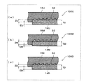
本実施例の電気化学式水素ポンプ200では、図4(a)および図4(b)に示す如く、締結器25による締結前において、水素ポンプユニット100Uのカソードガス拡散層14Uの厚みTUが、水素ポンプユニット100Mのカソードガス拡散層14Mの厚みTMよりも大きい。よって、この場合、カソードセパレーター16Uの凹部の深さとカソードセパレーター16Mの凹部の深さとが同じであると、締結器25による締結前において、カソードセパレーター16Uの凹部から突出するカソードガス拡散層14Uの厚みEUは、カソードセパレーター16Mの凹部から突出するカソードガス拡散層14Mの厚みEMよりも大きい。
In the
また、本実施例の電気化学式水素ポンプ200では、図4(b)および図4(c)に示す如く、締結器25による締結前において、水素ポンプユニット100Dのカソードガス拡散層14Dの厚みTDが、水素ポンプユニット100Mのカソードガス拡散層14Mの厚みTMよりも大きい。よって、この場合、カソードセパレーター16Dの凹部の深さとカソードセパレーター16Mの凹部の深さとが同じであると、締結器25による締結前において、カソードセパレーター16Dの凹部から突出するカソードガス拡散層14Dの厚みEDは、カソードセパレーター16Mの凹部から突出するカソードガス拡散層14Mの厚みEMよりも大きい。
Further, in the
以上の構成により、本実施例の電気化学式水素ポンプ200では、水素ポンプユニット100Uのカソードガス拡散層14Uが締結器25の締結によって圧縮される厚みを、適切に、水素ポンプユニット100Mのカソードガス拡散層14Mが締結器25の締結によって圧縮される厚みよりも大きくすることができる。また、水素ポンプユニット100Dのカソードガス拡散層14Dが締結器25の締結によって圧縮される厚みを、適切に、水素ポンプユニット100Mのカソードガス拡散層14Mが締結器25の締結によって圧縮される厚みよりも大きくすることができる。
With the above configuration, in the
本実施例の電気化学式水素ポンプ200は、上記の特徴以外は、第1実施形態の電気化学式水素ポンプ200と同様であってもよい。
Except for the features described above, the
(第2実施例)
図5は、第1実施形態の第2実施例の電気化学式水素ポンプの一例を示す図である。
(Second embodiment)
FIG. 5 is a diagram illustrating an example of an electrochemical hydrogen pump according to a second example of the first embodiment.
図5(a)には、締結器25による締結前における上段の水素ポンプユニット100U(図2Aおよび図3A参照)のカソードセパレーター16Uの凹部から突出するカソードガス拡散層14Uの様子が示されている。
FIG. 5A shows a state of the cathode
図5(b)には、締結器25による締結前における中段の水素ポンプユニット100M(図2Aおよび図3A参照)のカソードセパレーター16Mの凹部から突出するカソードガス拡散層14Mの様子が示されている。
FIG. 5B shows a state of the cathode
図5(c)には、締結器25による締結前における下段の水素ポンプユニット100D(図2Aおよび図3A参照)のカソードセパレーター16Dの凹部から突出するカソードガス拡散層14Dの様子が示されている。
FIG. 5C shows a state of the cathode
本実施例の電気化学式水素ポンプ200では、図5(a)および図5(b)に示す如く、水素ポンプユニット100Uのカソードセパレーター16Uの凹部の深さZUは、水素ポンプユニット100Mのカソードセパレーター16Mの凹部の深さZMよりも浅い。よって、この場合、締結器25による締結前における、カソードガス拡散層14Uの厚みTUとカソードガス拡散層14Mの厚みTMとが同じであると、締結器25による締結前において、カソードセパレーター16Uの凹部から突出するカソードガス拡散層14Uの厚みEUは、水素ポンプユニット100Mのカソードセパレーター16Mの凹部から突出するカソードガス拡散層14Mの厚みEMよりも大きい。
In the
また、本実施例の電気化学式水素ポンプ200では、図5(b)および図5(c)に示す如く、水素ポンプユニット100Dのカソードセパレーター16Dの凹部の深さZDは、水素ポンプユニット100Mのカソードセパレーター16Mの凹部の深さZMよりも浅い。よって、この場合、締結器25による締結前における、カソードガス拡散層14Dの厚みTDとカソードガス拡散層14Mの厚みTMとが同じであると、締結器25による締結前において、カソードセパレーター16Dの凹部から突出するカソードガス拡散層14Dの厚みEDは、水素ポンプユニット100Mのカソードセパレーター16Mの凹部から突出するカソードガス拡散層14Mの厚みEMよりも大きい。
In addition, in the
以上の構成により、本実施例の電気化学式水素ポンプ200は、水素ポンプユニット100Uのカソードガス拡散層14Uの厚みTUと水素ポンプユニット100Mのカソードガス拡散層14Mの厚みTMとが同じ場合でも、カソードガス拡散層14Uが締結器25の締結によって圧縮される厚みを、適切に、カソードガス拡散層14Mが締結器25の締結によって圧縮される厚みよりも大きくすることができる。また、水素ポンプユニット100Dのカソードガス拡散層14Dの厚みTDと水素ポンプユニット100Mのカソードガス拡散層14Mの厚みTMとが同じ場合でも、カソードガス拡散層14Dが締結器25の締結によって圧縮される厚みを、適切に、カソードガス拡散層14Mが締結器25の締結によって圧縮される厚みよりも大きくすることができる。
With the above configuration, the
本実施例の電気化学式水素ポンプ200は、上記の特徴以外は、第1実施形態または第1実施形態の第1実施例の電気化学式水素ポンプ200と同様であってもよい。
Except for the features described above, the
(第1変形例)
本変形例の電気化学式水素ポンプ200は、積層された水素ポンプユニット100の両端の少なくとも一方の端に位置する水素ポンプユニット100のカソードガス拡散層14のカソードセパレーター16側の主面に、凸部が設けられていること以外は、第1実施形態および第1実施形態の第1実施例−第2実施例のいずれかの電気化学式水素ポンプ200と同様である。
(First Modification)
The
図6Aおよび図6Bは、第1実施形態の第1変形例の電気化学式水素ポンプの一例を示す図である。 FIGS. 6A and 6B are diagrams illustrating an example of an electrochemical hydrogen pump according to a first modification of the first embodiment.
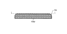
上記のとおり、カソード端板24Cに近接する上段の水素ポンプユニット100Uのカソードガス拡散層14Uのガス圧が高圧になると、このカソードセパレーター16Uは、カソード端板24C側(外側)に膨らむように変形する。すると、カソードガス拡散層14U側のカソードセパレーター16Uの主面Sは、高圧の水素含有ガスによって中央部の変形量が端部の変形量に比べて大きくなるように変形する。つまり、カソードセパレーター16Uの主面Sが、高圧の水素含有ガスによってドーム状に変形する。
As described above, when the gas pressure of the cathode
なお、かかる現象は、図6Aに示す如く、カソードガス拡散層14Uを設置する凹部が設けているカソードセパレーター16U、および、図6Bに示す如く、このような凹部が設けられていないカソードセパレーターのいずれの形態においても発生する。
In addition, such a phenomenon is caused by either a
そこで、本変形例の電気化学式水素ポンプ200は、カソードガス拡散層14Uのカソードセパレーター16U側の主面に凸部70を設けることで、カソードガス拡散層14Uの主面が、高圧の水素含有ガスによってドーム状に変形するカソードセパレーター16Uの主面Sと密着しやすいように構成されている。よって、本変形例の電気化学式水素ポンプ200は、カソードガス拡散層14Uの主面に凸部70を設けない場合に比べて、カソードセパレーター16Uとカソードガス拡散層14Uとの間に隙間が生じる可能性を低減することができる。
Therefore, in the
本変形例の電気化学式水素ポンプ200は、上記の特徴以外は、第1実施形態および第1実施形態の第1実施例−第2実施例のいずれかの電気化学式水素ポンプ200と同様であってもよい。
The
(第2変形例)
カソードガス拡散層14の厚み方向の電気抵抗は、カソードガス拡散層14の厚みに比例する。また、上段の水素ポンプユニット100Uおよび下段の水素ポンプユニット100Dでは、中段の水素ポンプユニット100Mに比べて、締結器25の締結により圧縮される厚みが大きい。よって、水素ポンプユニット100U、100Dのカソードガス拡散層14の厚み方向の電気抵抗は、水素ポンプユニット100Mのカソードガス拡散層14の厚み方向の電気抵抗よりも締結器25による締結に伴って低下しやすい。
(Second Modification)
The electric resistance in the thickness direction of the cathode
そこで、本変形例の電気化学式水素ポンプ200は、締結器25による締結前において、積層された水素ポンプユニット100の両端の少なくとも一方の端に位置する水素ポンプユニット100(図2Aおよび図3Aでは、水素ポンプユニット100U、100D)のカソードガス拡散層14の厚み方向の電気抵抗を、積層された水素ポンプユニット100の両端に位置しない水素ポンプユニット100(図2Aおよび図3Aでは、水素ポンプユニット100M)のカソードガス拡散層14の厚み方向の電気抵抗よりも大きくするように構成されている。
Therefore, the
締結器25による締結前において、カソードガス拡散層14の厚み方向の電気抵抗を増減させる構成は、どのようなものであってもよいが、例えば、多孔性のカソードガス拡散層14の空隙率を変化させることで、カソードガス拡散層14の厚み方向の電気抵抗を増減させることができる。つまり、この場合、締結器25による締結前において、水素ポンプユニット100U、100Dのカソードガス拡散層14の空隙率を、水素ポンプユニット100Mのカソードガス拡散層14の空隙率よりも高くするとよい。
Before the fastening by the
また、例えば、カソードガス拡散層14の材料を変えることで、カソードガス拡散層14の厚み方向の電気抵抗を増減させることもできる。つまり、この場合、水素ポンプユニット100U、100Dでは、水素ポンプユニット100Mに比べて、電気抵抗率が高い材料を用いるとよい。
Further, for example, by changing the material of the cathode
以上の構成により、本変形例の電気化学式水素ポンプ200は、締結器25による締結時において、水素ポンプユニット100U、100M、100Dのそれぞれのカソードガス拡散層14の厚み方向の電気抵抗を均一化させやすくすることができる。
With the configuration described above, the
つまり、本変形例の電気化学式水素ポンプ200は、締結器25による締結に伴って生じる水素ポンプユニット100U、100M、100Dのそれぞれのカソードガス拡散層14の厚み方向の電気抵抗低下のバラツキを、締結器25による締結前における水素ポンプユニット100U、100M、100Dのそれぞれのカソードガス拡散層14の厚み方向の電気抵抗の不均一性で相殺させることができる。
In other words, the
よって、本変形例の電気化学式水素ポンプ200は、締結器25による締結前において、水素ポンプユニット100U、100M、100Dのそれぞれのカソードガス拡散層14の厚み方向の電気抵抗が均等である場合に比べて、締結器25による締結時における水素ポンプユニット100U、100M、100Dのそれぞれのカソードガス拡散層14の厚み方向の電気抵抗が均一化し得る。
Therefore, the
なお、仮に、締結器25による締結時における水素ポンプユニット100U、100M、100Dのそれぞれのカソードガス拡散層14の厚み方向の電気抵抗が不均一であると、電気化学式水素ポンプ200の運転時(電流通電時)に、水素ポンプユニット100U、100M、100D間で発熱量が異なることで水素ポンプユニット100U、100M、100D間の動作温度が相違する恐れがある。しかし、本変形例の電気化学式水素ポンプ200は、上記の構成により、このような不都合が生じる可能性を低減できる。
If the electric resistance in the thickness direction of each of the cathode gas diffusion layers 14 of the
本変形例の電気化学式水素ポンプ200は、上記の特徴以外は、第1実施形態、第1実施形態の第1実施例−第2実施例および第1実施形態の第1変形例のいずれかの電気化学式水素ポンプ200と同様であってもよい。
Except for the features described above, the
(第2実施形態)
図7は、第2実施形態の電気化学式水素ポンプの一例を示す図である。
(2nd Embodiment)
FIG. 7 is a diagram illustrating an example of the electrochemical hydrogen pump according to the second embodiment.
図7には、平面視において電気化学式水素ポンプ200の中心と、カソードガス導出マニホールド50の中心と、を通過する直線を含む電気化学式水素ポンプ200の垂直断面が示されている。
FIG. 7 shows a vertical cross section of the
本実施形態の電気化学式水素ポンプ200は、以下に説明する第一空間60および第1ガス流路を備えること、および、上段の水素ポンプユニット100Uと下段の水素ポンプユニット100Dとで締結器25の締結によりカソードガス拡散層14(図2B参照)が圧縮される厚みが異なること以外は、第1実施形態の電気化学式水素ポンプ200と同様である。
The
本実施形態の電気化学式水素ポンプ200は、カソード端板24Cと、水素ポンプユニット100のうちカソード端板24C側の端に位置する水素ポンプユニット100Uとの間に、カソードガス流路32から排出された水素含有ガスを貯える第一空間60が設けられている。
The
また、電気化学式水素ポンプ200は、カソード端板24Cと水素ポンプユニット100Uのカソードセパレーター16Uとの間に設けられた第一空間60にカソードCAで生成される水素含有ガスを供給するための第1ガス流路を備える。
In addition, the
第一空間60は、カソード端板24Cとカソードセパレーター16Uとの間に設けられた空間であれば、どのような構成であってもよい。また、第1ガス流路は、第一空間60にカソードCAで生成される水素含有ガスを供給するための流路であれば、どのような構成であってもよい。
The
例えば、本実施形態の電気化学式水素ポンプ200では、図7に示す如く、第1ガス流路は、筒状のカソードガス導出マニホールド50と、カソードガス導出マニホールド50と第一空間60とを連通するカソードガス供給経路51とを備える。
For example, in the
ここで、第一空間60は、カソード端板24Cの中央部に設けられた凹部とカソード絶縁板23Cの中央部に設けられた開口とによって構成されている。
Here, the
また、カソードガス供給経路51は、カソード端板24Cの凹部内(第一空間60)とカソードガス導出マニホールド50の端部とを連通するカソード端板24Cの主面に設けられた溝によって構成されている。
Further, the cathode
このようにして、本実施形態の電気化学式水素ポンプ200は、水素ポンプユニット100のカソードCAで生成される高圧の水素含有ガスを、カソードガス導出マニホールド50およびカソードガス供給経路51を通じてカソード端板24Cとカソードセパレーター16との間に設けられた第一空間60に供給することができる。つまり、第一空間60内に高圧の水素含有ガスを滞留させることができる。
In this way, the
ここで、水素ポンプユニット100Uとカソード端板24Cとの間に設けられた第一空間60の水素含有ガス圧は、水素ポンプユニット100のカソードCA内の水素含有ガス圧とほぼ同等の高圧である。すると、第一空間60内の水素含有ガスによって、水素ポンプユニット100Uのカソードセパレーター16Uに付与される荷重は、カソードCA内の水素含有ガス圧に起因するカソードセパレーター16Uの変形(たわみ)を抑えるように作用する。
Here, the hydrogen-containing gas pressure in the
これに対して、水素ポンプユニット100Dとアノード端板24Aとの間には、水素ポンプユニット100のカソードCA内の水素含有ガス圧とほぼ同等の高圧の水素含有ガスを貯える空間が存在しない。このため、水素ポンプユニット100Dのアノードセパレーター17Dには、カソードCA内の水素含有ガス圧に起因するアノードセパレーター17Dの変形(たわみ)を抑えるような荷重が付与されない。つまり、水素ポンプユニット100Dでは、水素ポンプユニット100Uに比べて、水素ポンプユニット100のカソードCA内の水素含有ガス圧によって、水素ポンプユニット100Dを構成する部材間に隙間が生じやすくなる。
On the other hand, there is no space between the
そこで、本実施形態の電気化学式水素ポンプ200は、締結器25の締結によりカソードガス拡散層14が圧縮される厚みの大きさが、水素ポンプユニット100Dのカソードガス拡散層14の方が、水素ポンプユニット100Uのカソードガス拡散層14よりも大きくなるように構成されている。なお、このとき、締結器25の締結により水素ポンプユニット100Uのカソードガス拡散層14が圧縮される厚みは、締結器25の締結により水素ポンプユニット100Mのカソードガス拡散層14が圧縮される厚みとほぼ同じであってもよい。
Therefore, in the
以上により、本実施形態の電気化学式水素ポンプ200は、水素ポンプユニット100Dを構成する部材間に隙間が生じる可能性を低減することができる。
As described above, the
本実施形態の電気化学式水素ポンプ200は、上記の特徴以外は、第1実施形態、第1実施形態の第1実施例−第2実施例および第1実施形態の第1変形例−第2変形例のいずれかの電気化学式水素ポンプ200と同様であってもよい。
Except for the features described above, the
(第3実施形態)
図8は、第3実施形態の電気化学式水素ポンプの一例を示す図である。
(Third embodiment)
FIG. 8 is a diagram illustrating an example of an electrochemical hydrogen pump according to the third embodiment.
図8には、平面視において電気化学式水素ポンプ200の中心と、カソードガス導出マニホールド50の中心と、を通過する直線を含む電気化学式水素ポンプ200の垂直断面が示されている。
FIG. 8 shows a vertical cross section of the
本実施形態の電気化学式水素ポンプ200は、以下に説明する第二空間61および第2ガス流路を備えること、および、上段の水素ポンプユニット100Uと下段の水素ポンプユニット100Dとで締結器25の締結によりカソードガス拡散層14(図2B参照)が圧縮される厚みが異なること以外は、第1実施形態の電気化学式水素ポンプ200と同様である。
The
本実施形態の電気化学式水素ポンプ200は、アノード端板24Aと、水素ポンプユニット100のうちアノード端板24A側の端に位置する水素ポンプユニット100Dとの間に、カソードガス流路32から排出された水素含有ガスを貯える第二空間61が設けられている。
The
また、電気化学式水素ポンプ200は、アノード端板24Aと水素ポンプユニット100Dのアノードセパレーター17Dとの間に設けられた第二空間61にカソードCAで生成される水素含有ガスを供給するための第2ガス流路を備える。
In addition, the
第二空間61は、アノード端板24Aとアノードセパレーター17Dとの間に設けられた空間であれば、どのような構成であってもよい。また、第2ガス流路は、第二空間61にカソードCAで生成される水素含有ガスを供給するための流路であれば、どのような構成であってもよい。
The
例えば、本実施形態の電気化学式水素ポンプ200では、図8に示す如く、第2ガス流路は、筒状のカソードガス導出マニホールド50と、カソードガス導出マニホールド50と第二空間61とを連通するカソードガス供給経路52とを備える。
For example, in the
ここで、第二空間61は、アノード端板24Aの中央部に設けられた凹部とアノード絶縁板23Aの中央部に設けられた開口とによって構成されている。
Here, the
また、カソードガス供給経路52は、アノード端板24Aの凹部内(第二空間61)とカソードガス導出マニホールド50の端部とを連通するアノード端板24Aの主面に設けられた溝によって構成されている。
Further, the cathode
このようにして、本実施形態の電気化学式水素ポンプ200は、水素ポンプユニット100のカソードCAで生成される高圧の水素含有ガスを、カソードガス導出マニホールド50およびカソードガス供給経路52を通じてアノード端板24Aとアノードセパレーター17Dとの間に設けられた第二空間61に供給することができる。つまり、第二空間61内に高圧の水素含有ガスを滞留させることができる。
In this manner, the
ここで、水素ポンプユニット100Dとアノード端板24Aとの間に設けられた第二空間61の水素含有ガス圧は、水素ポンプユニット100のカソードCA内の水素含有ガス圧とほぼ同等の高圧である。すると、第二空間61内の水素含有ガスによって、水素ポンプユニット100Dのアノードセパレーター17Dに付与される荷重は、カソードCA内の水素含有ガス圧に起因するアノードセパレーター17Dの変形(たわみ)を抑えるように作用する。
Here, the hydrogen-containing gas pressure in the
これに対して、水素ポンプユニット100Uとカソード端板24Cとの間には、水素ポンプユニット100のカソードCA内の水素含有ガス圧とほぼ同等の高圧の水素含有ガスを貯える空間が存在しない。このため、水素ポンプユニット100Uのカソードセパレーター16Uには、カソードCA内の水素含有ガス圧に起因するカソードセパレーター16Uの変形(たわみ)を抑えるような荷重が付与されない。つまり、水素ポンプユニット100Uでは、水素ポンプユニット100Dに比べて、水素ポンプユニット100のカソードCA内の水素含有ガス圧によって、水素ポンプユニット100Uを構成する部材間に隙間が生じやすくなる。
In contrast, there is no space between the
そこで、本実施形態の電気化学式水素ポンプ200は、締結器25の締結によりカソードガス拡散層14が圧縮される厚みの大きさが、水素ポンプユニット100Uのカソードガス拡散層14の方が、水素ポンプユニット100Dのカソードガス拡散層14よりも大きくなるように構成されている。なお、このとき、締結器25の締結により水素ポンプユニット100Dのカソードガス拡散層14が圧縮される厚みは、締結器25の締結により水素ポンプユニット100Mのカソードガス拡散層14が圧縮される厚みとほぼ同じであってもよい。
Therefore, in the
以上により、本実施形態の電気化学式水素ポンプ200は、水素ポンプユニット100Uを構成する部材間に隙間が生じる可能性を低減することができる。
As described above, the
本実施形態の電気化学式水素ポンプ200は、上記の特徴以外は、第1実施形態、第1実施形態の第1実施例−第2実施例および第1実施形態の第1変形例−第2変形例のいずれかの電気化学式水素ポンプ200と同様であってもよい。
Except for the features described above, the
第1実施形態、第1実施形態の第1実施例−第2実施例、第1実施形態の第1変形例−第2変形例、第2実施形態および第3実施形態は、互いに相手を排除しない限り、互いに組み合わせても構わない。 The first embodiment, the first embodiment of the first embodiment, the second embodiment, the first modification of the first embodiment, the second modification, the second embodiment, and the third embodiment exclude each other. Unless otherwise specified, they may be combined with each other.
上記説明から、当業者にとっては、本開示の多くの改良や他の実施形態が明らかである。従って、上記説明は、例示としてのみ解釈されるべきであり、本開示を実行する最良の態様を当業者に教示する目的で提供されたものである。本開示の精神を逸脱することなく、その構造および/または機能の詳細を実質的に変更できる。 From the above description, many modifications and other embodiments of the present disclosure are obvious to one skilled in the art. Therefore, the above description is to be construed as illustrative only and is provided for the purpose of teaching those skilled in the art the best mode of carrying out the present disclosure. The details of the structure and / or function may be substantially changed without departing from the spirit of the present disclosure.
本開示の一態様は、従来に比べて、水素ポンプユニットを構成する部材間の接触抵抗の増加を簡易かつ適切に抑制し得る電気化学式水素ポンプに利用することができる。 One embodiment of the present disclosure can be used for an electrochemical hydrogen pump that can easily and appropriately suppress an increase in contact resistance between members constituting a hydrogen pump unit as compared with the related art.
11 :電解質膜
12 :カソード触媒層
13 :アノード触媒層
14 :カソードガス拡散層
14D :カソードガス拡散層
14M :カソードガス拡散層
14U :カソードガス拡散層
15 :アノードガス拡散層
16 :カソードセパレーター
16D :カソードセパレーター
16M :カソードセパレーター
16U :カソードセパレーター
17 :アノードセパレーター
17D :アノードセパレーター
21 :絶縁体
22A :アノード給電板
22C :カソード給電板
23A :アノード絶縁板
23C :カソード絶縁板
24A :アノード端板
24C :カソード端板
25 :締結器
26 :カソードガス導出経路
27 :アノードガス導入マニホールド
29 :アノードガス導入経路
30 :アノードガス導出マニホールド
31 :アノードガス導出経路
32 :カソードガス流路
33 :アノードガス流路
34 :カソードガス通過経路
35 :第1アノードガス通過経路
36 :第2アノードガス通過経路
40 :シール部材
42 :シール部材
43 :シール部材
50 :カソードガス導出マニホールド
51 :カソードガス供給経路
52 :カソードガス供給経路
60 :第一空間
61 :第二空間
70 :凸部
100 :水素ポンプユニット
100D :水素ポンプユニット
100M :水素ポンプユニット
100U :水素ポンプユニット
102 :電圧印加器
200 :電気化学式水素ポンプ
AN :アノード
CA :カソード
11: electrolyte membrane 12: cathode catalyst layer 13: anode catalyst layer 14: cathode
Claims (8)
少なくとも3つ以上の積層された前記水素ポンプユニットの積層方向の両端上に設けられた第1の端板および第2の端板と、前記第1の端板と前記第2の端板を締結して、前記水素ポンプユニットを積層方向に圧縮する締結器と、を備え、
少なくとも3つ以上の積層された前記水素ポンプユニットの前記カソードガス拡散層から流出するカソードガスが流れるカソードガス流路は連通されており、
前記締結器の締結により前記カソードガス拡散層が圧縮される厚みの大きさは、前記積層された水素ポンプユニットの両端の少なくとも一方の端に位置する前記水素ポンプユニットの前記カソードガス拡散層の方が、前記積層された水素ポンプユニットの両端に位置しない前記水素ポンプユニットの前記カソードガス拡散層よりも大きい電気化学式水素ポンプ。 An electrolyte membrane, an anode catalyst layer provided on one main surface of the electrolyte membrane, a cathode catalyst layer provided on the other main surface of the electrolyte membrane, and an anode gas diffusion layer provided on the anode catalyst layer An anode separator provided on the anode gas diffusion layer, a cathode gas diffusion layer provided on the cathode catalyst layer, and a hydrogen pump unit including a cathode separator provided on the cathode gas diffusion layer,
Fastening a first end plate and a second end plate provided on both ends in the stacking direction of at least three or more of the stacked hydrogen pump units, and fastening the first end plate and the second end plate. And a fastener for compressing the hydrogen pump unit in the stacking direction,
A cathode gas flow path through which a cathode gas flowing from the cathode gas diffusion layer of the at least three or more stacked hydrogen pump units flows is connected,
The magnitude of the thickness of the compressed cathode gas diffusion layer by the fastening of the fastener is greater than the thickness of the cathode gas diffusion layer of the hydrogen pump unit located at at least one end of both ends of the stacked hydrogen pump unit. However, an electrochemical hydrogen pump that is larger than the cathode gas diffusion layer of the hydrogen pump unit that is not located at both ends of the stacked hydrogen pump unit.
前記積層された水素ポンプユニットの両端の少なくとも一方の端に位置する前記水素ポンプユニットの前記カソードガス拡散層の厚みが、前記積層された水素ポンプユニットの両端に位置しない前記水素ポンプユニットの前記カソードガス拡散層の厚みよりも大きい請求項1に記載の電気化学式水素ポンプ。 Before fastening by the fastener,
The thickness of the cathode gas diffusion layer of the hydrogen pump unit located at at least one end of both ends of the stacked hydrogen pump unit, the cathode of the hydrogen pump unit not located at both ends of the stacked hydrogen pump unit The electrochemical hydrogen pump according to claim 1, wherein the thickness of the gas diffusion layer is larger than the thickness of the gas diffusion layer.
前記締結器による締結前において、
前記積層された水素ポンプユニットの両端の少なくとも一方の端に位置する前記水素ポンプユニットの前記カソードセパレーターの凹部から突出する前記カソードガス拡散層の厚みは、前記積層された水素ポンプユニットの両端に位置しない前記水素ポンプユニットの前記カソードセパレーターの凹部から突出する前記カソードガス拡散層の厚みよりも大きい請求項1に記載の電気化学式水素ポンプ。 The cathode separator is provided with a recess for installing the cathode gas diffusion layer,
Before fastening by the fastener,
The thickness of the cathode gas diffusion layer protruding from the recess of the cathode separator of the hydrogen pump unit located at at least one end of both ends of the stacked hydrogen pump unit is located at both ends of the stacked hydrogen pump unit. The electrochemical hydrogen pump according to claim 1, wherein the thickness of the cathode gas diffusion layer protruding from a concave portion of the cathode separator of the hydrogen pump unit is not increased.
前記積層された水素ポンプユニットの両端の少なくとも一方の端に位置する前記水素ポンプユニットの前記カソードガス拡散層の厚み方向の電気抵抗が、前記積層された水素ポンプユニットの両端に位置しない前記水素ポンプユニットの前記カソードガス拡散層の厚み方向の電気抵抗よりも大きい請求項1−5のいずれか1項に記載の電気化学式水素ポンプ。 Before fastening by the fastener,
The hydrogen pump wherein the electric resistance in the thickness direction of the cathode gas diffusion layer of the hydrogen pump unit located at at least one end of both ends of the stacked hydrogen pump unit is not located at both ends of the stacked hydrogen pump unit. The electrochemical hydrogen pump according to any one of claims 1 to 5, wherein the electrical resistance is greater than the electrical resistance of the unit in the thickness direction of the cathode gas diffusion layer.
前記締結器の締結により前記カソードガス拡散層が圧縮される厚みの大きさは、前記積層された水素ポンプユニットのうち前記第2の端板側の端に位置する前記水素ポンプユニットの前記カソードガス拡散層の方が、前記積層された水素ポンプユニットのうち前記第1の端板側の端に位置する前記水素ポンプユニットの前記カソードガス拡散層よりも大きい請求項1−6のいずれか1項に記載の電気化学式水素ポンプ。 A hydrogen-containing gas discharged from the cathode gas flow path between the first end plate and the hydrogen pump unit located at the end of the stacked hydrogen pump units on the first end plate side. The first space to store
The thickness of the thickness of the cathode gas diffusion layer compressed by the fastening of the fastener is determined by the cathode gas of the hydrogen pump unit located at the end on the second end plate side of the stacked hydrogen pump units. The diffusion layer is larger than the cathode gas diffusion layer of the hydrogen pump unit located at the end on the first end plate side of the stacked hydrogen pump units. An electrochemical hydrogen pump according to claim 1.
前記締結器の締結により前記カソードガス拡散層が圧縮される厚みの大きさは、前記積層された水素ポンプユニットのうち前記第1の端板側に位置する前記水素ポンプユニットの前記カソードガス拡散層の方が、前記積層された水素ポンプユニットのうち前記第2の端板側の端に位置する前記水素ポンプユニットの前記カソードガス拡散層よりも大きい請求項1−6のいずれか1項に記載の電気化学式水素ポンプ。
A hydrogen-containing gas discharged from the cathode gas flow path between the second end plate and the hydrogen pump unit located at the end on the second end plate side of the stacked hydrogen pump units; A second space for storing
The thickness of the thickness of the cathode gas diffusion layer compressed by the fastening of the fastener is the cathode gas diffusion layer of the hydrogen pump unit located on the first end plate side of the stacked hydrogen pump units. 7 is larger than the cathode gas diffusion layer of the hydrogen pump unit located at the end on the second end plate side of the stacked hydrogen pump units. 8. Electrochemical hydrogen pump.
Applications Claiming Priority (2)
| Application Number | Priority Date | Filing Date | Title |
|---|---|---|---|
| JP2018126981 | 2018-07-03 | ||
| JP2018126981 | 2018-07-03 |
Publications (1)
| Publication Number | Publication Date |
|---|---|
| JP2020007634A true JP2020007634A (en) | 2020-01-16 |
Family
ID=67105874
Family Applications (1)
| Application Number | Title | Priority Date | Filing Date |
|---|---|---|---|
| JP2019110245A Withdrawn JP2020007634A (en) | 2018-07-03 | 2019-06-13 | Electrochemical hydrogen pump |
Country Status (4)
| Country | Link |
|---|---|
| US (1) | US10989184B2 (en) |
| EP (1) | EP3591754A1 (en) |
| JP (1) | JP2020007634A (en) |
| CN (1) | CN110670088A (en) |
Families Citing this family (7)
| Publication number | Priority date | Publication date | Assignee | Title |
|---|---|---|---|---|
| JP7209221B2 (en) * | 2018-07-23 | 2023-01-20 | パナソニックIpマネジメント株式会社 | electrochemical hydrogen pump |
| US11549187B2 (en) * | 2018-10-18 | 2023-01-10 | Panasonic Intellectual Property Management Co., Ltd. | Electrochemical hydrogen pump |
| EP4141146B1 (en) * | 2020-04-20 | 2025-10-01 | Panasonic Intellectual Property Management Co., Ltd. | Compression device |
| WO2021215088A1 (en) * | 2020-04-20 | 2021-10-28 | パナソニックIpマネジメント株式会社 | Compression device |
| EP4219392A4 (en) * | 2020-09-25 | 2024-11-27 | Panasonic Intellectual Property Management Co., Ltd. | ANODE SEPARATOR FOR ELECTROCHEMICAL HYDROGEN PUMP AND ELECTROCHEMICAL HYDROGEN PUMP |
| WO2022064816A1 (en) * | 2020-09-25 | 2022-03-31 | パナソニックIpマネジメント株式会社 | Compression device |
| JP7016035B1 (en) * | 2020-11-10 | 2022-02-04 | パナソニックIpマネジメント株式会社 | Compressor |
Family Cites Families (11)
| Publication number | Priority date | Publication date | Assignee | Title |
|---|---|---|---|---|
| JP2006070322A (en) | 2004-09-02 | 2006-03-16 | Honda Motor Co Ltd | High pressure hydrogen production device |
| JP4165655B2 (en) | 2005-02-25 | 2008-10-15 | 本田技研工業株式会社 | Electrolytic device, electrochemical reaction membrane device, and porous conductor |
| US20060199061A1 (en) * | 2005-03-02 | 2006-09-07 | Fiebig Bradley N | Water management in bipolar electrochemical cell stacks |
| KR20060108921A (en) * | 2005-04-13 | 2006-10-18 | 삼성에스디아이 주식회사 | Fuel cell systems and stacks |
| JP2006307248A (en) | 2005-04-26 | 2006-11-09 | Honda Motor Co Ltd | Hydrogen production equipment |
| JP4597800B2 (en) * | 2005-07-19 | 2010-12-15 | 本田技研工業株式会社 | High pressure hydrogen production equipment |
| JP5077358B2 (en) * | 2008-08-07 | 2012-11-21 | パナソニック株式会社 | Fuel cell stack and fuel cell system using the same |
| JP4717160B2 (en) * | 2009-10-13 | 2011-07-06 | パナソニック株式会社 | Fuel cell and manufacturing method thereof |
| US10011912B2 (en) * | 2013-08-05 | 2018-07-03 | University Of Yamanashi | Hydrogen refining pressure-boosting device |
| JP2018090899A (en) * | 2016-12-06 | 2018-06-14 | パナソニックIpマネジメント株式会社 | Electrochemical hydrogen pump |
| JP6887100B2 (en) * | 2016-12-26 | 2021-06-16 | パナソニックIpマネジメント株式会社 | Membrane electrode assembly and electrochemical hydrogen pump |
-
2019
- 2019-06-13 JP JP2019110245A patent/JP2020007634A/en not_active Withdrawn
- 2019-06-17 US US16/442,578 patent/US10989184B2/en not_active Expired - Fee Related
- 2019-06-27 CN CN201910565208.0A patent/CN110670088A/en active Pending
- 2019-06-27 EP EP19182879.7A patent/EP3591754A1/en not_active Withdrawn
Also Published As
| Publication number | Publication date |
|---|---|
| US20200011313A1 (en) | 2020-01-09 |
| CN110670088A (en) | 2020-01-10 |
| EP3591754A1 (en) | 2020-01-08 |
| US10989184B2 (en) | 2021-04-27 |
Similar Documents
| Publication | Publication Date | Title |
|---|---|---|
| JP7426597B2 (en) | electrochemical hydrogen pump | |
| JP7209221B2 (en) | electrochemical hydrogen pump | |
| JP2020007634A (en) | Electrochemical hydrogen pump | |
| JP7555003B2 (en) | Electrochemical Hydrogen Pump | |
| JP6979637B2 (en) | Compressor | |
| JP6719076B1 (en) | Electrochemical hydrogen pump | |
| JP6928921B1 (en) | Compressor | |
| JP6928922B1 (en) | Compressor | |
| JP2020015930A (en) | Electrochemical hydrogen pump | |
| JP2019163521A (en) | Electrochemical type hydrogen pump | |
| JP6956392B1 (en) | Compressor | |
| US20240060190A1 (en) | Electrochemical cell for hydrogen pump and compression apparatus | |
| JP6979634B1 (en) | Compressor | |
| WO2023100583A1 (en) | Compression device | |
| JP7345104B1 (en) | compression device | |
| JP6979636B1 (en) | Compressor |
Legal Events
| Date | Code | Title | Description |
|---|---|---|---|
| A621 | Written request for application examination |
Free format text: JAPANESE INTERMEDIATE CODE: A621 Effective date: 20220117 |
|
| A761 | Written withdrawal of application |
Free format text: JAPANESE INTERMEDIATE CODE: A761 Effective date: 20221228 |
|
| A521 | Request for written amendment filed |
Free format text: JAPANESE INTERMEDIATE CODE: A523 Effective date: 20230120 |