JP2020007783A - Rail fastening device - Google Patents
Rail fastening device Download PDFInfo
- Publication number
- JP2020007783A JP2020007783A JP2018129593A JP2018129593A JP2020007783A JP 2020007783 A JP2020007783 A JP 2020007783A JP 2018129593 A JP2018129593 A JP 2018129593A JP 2018129593 A JP2018129593 A JP 2018129593A JP 2020007783 A JP2020007783 A JP 2020007783A
- Authority
- JP
- Japan
- Prior art keywords
- rail
- brace
- floor plate
- basic
- fastening device
- Prior art date
- Legal status (The legal status is an assumption and is not a legal conclusion. Google has not performed a legal analysis and makes no representation as to the accuracy of the status listed.)
- Granted
Links
Images


Landscapes
- Railway Tracks (AREA)
Abstract
【課題】レールの傾倒作業を伴うことなくレールブレスを設置することができる分岐器用レール締結装置を提供する。【解決手段】トングレールの摺動部と基本レールの載置部と摺動部の反対側の所定位置に設けられたばね保持部とを有する床板と、レール載置部に載置された基本レールの側面に接触した状態で床板に装着されるレールブレスと、ばね保持部に係合されレールブレスを介して本レールの下部フランジを床板へ向かって押圧するばね部材と、を備えたレール締結装置において、床板のばね保持部よりも外側の所定位置にレール載置部と所定角度をなすガイド溝を形成し、レールブレスには、ばね保持部との干渉を回避するための凹部を有し、先端に基本レールの顎部から腹部および下部フランジの一部かけての形状と対応する形状を有する押圧部を、また下面後端にガイド溝に係合可能な突出部を設け、一対の側壁のうち少なくとも一方に開口を設けた。【選択図】図4PROBLEM TO BE SOLVED: To provide a rail fastening device for a branching device capable of installing a rail breath without tilting the rail. SOLUTION: A floor plate having a sliding portion of a tongue rail, a mounting portion of a basic rail, and a spring holding portion provided at a predetermined position on the opposite side of the sliding portion, and a basic rail mounted on the rail mounting portion. A rail fastening device including a rail breath mounted on the floor plate in contact with the side surface of the rail, and a spring member engaged with the spring holding portion and pressing the lower flange of the rail toward the floor plate via the rail breath. In, a guide groove forming a predetermined angle with the rail mounting portion is formed at a predetermined position outside the spring holding portion of the floor plate, and the rail breath has a recess for avoiding interference with the spring holding portion. A pair of side walls are provided with a pressing portion having a shape corresponding to the shape from the jaw of the basic rail to the abdomen and a part of the lower flange at the tip, and a protruding portion that can be engaged with the guide groove at the rear end of the lower surface. An opening was provided in at least one of them. [Selection diagram] FIG. 4
Description
本発明は、鉄道軌道におけるレール締結装置に関し、特に分岐器においてトングレールからの横圧による基本レールのズレや小返りを防止するレールブレスに利用して有効な技術に関する。 The present invention relates to a rail fastening device for a railway track, and more particularly to a technology effective for use in a rail brace for preventing displacement and small return of a basic rail due to lateral pressure from a tong rail in a branching device.
従来、鉄道軌道の分岐器においては、軌道に沿って所定の間隔で配設されている枕木上に敷設された基本レールに対して、可動レールとしてのトングレールの先端側が、転轍器によって接近・離反可能に構成されている。分岐器用レール締結装置は、枕木上に固定され、基本レールを固定するとともに、載置されたトングレールを横方向へ摺動可能に支持する床板を備えている。そして、この床板に、トングレールの摺動面を有する載置台が設けられており、トングレールが転轍器によって基本レールに近づく方向へ移動される。基本レールのトングレール側には、トングレールが基本レールに近接する構成上、レール締結装置を設けることができず、列車荷重の横圧により、基本レールが小返りを起こすおそれがある。 Conventionally, in a railroad track switch, the tip side of a tong rail as a movable rail approaches a basic rail laid on a sleeper provided at a predetermined interval along the track by a switch.・ It is configured to be detachable. The turnout rail fastening device includes a floor plate that is fixed on a sleeper, fixes a basic rail, and supports a mounted tong rail so as to be slidable in a lateral direction. A mounting table having a sliding surface of a tong rail is provided on the floor plate, and the tong rail is moved in a direction approaching the basic rail by a switch. A rail fastening device cannot be provided on the tongue rail side of the basic rail because the tongue rail is close to the basic rail, and the basic rail may cause a slight return due to the lateral pressure of the train load.
そこで、分岐器には、基本レールの反対側の側面に当接することで、基本レールのズレや小返りを防止するレールブレスと呼ばれるブロックを備えたレール締結装置が設けられている(特許文献1、2参照)。
なお、枕木上にはレールの基部(フランジ部)に当接して押さえ込むことでレールを締結する線ばねクリップを装着するためのショルダーと呼ばれる部材が設けられており、レールブレスはショルダーに係止された線ばねクリップによって押さえ込むようにして枕木上に固定される。
Therefore, the branching device is provided with a rail fastening device provided with a block called a rail brace for preventing the basic rail from shifting or slightly returning by contacting the side surface on the opposite side of the basic rail (Patent Document 1). , 2).
In addition, a member called a shoulder is provided on the sleeper for attaching a wire spring clip that fastens the rail by abutting against the base (flange portion) of the rail and pressing down, and the rail brace is locked to the shoulder. It is fixed on the sleeper so that it is held down by the wire spring clip.
しかしながら、上記特許文献1および2のレール締結装置は、いずれもレールブレスの先端部をレールの長さ方向と直交する方向からレール側面凹部に当接させた状態で線ばねクリップによって押さえ込むという構成であるので、レールブレスをレール側面凹部に当接させる際に、レールブレスの上端とレール頭頂部との干渉を避けるようにして係合させる必要があるため、バール等を使用してレールを小返しつまり傾ける必要がある。
しかも、レールの長さは10数メートルもあるため、レールの傾倒にはかなり大きな力が必要となり、数人がかりで作業する必要がある。
However, each of the rail fastening devices of Patent Documents 1 and 2 has a configuration in which the distal end of the rail brace is pressed by a wire spring clip in a state in which the distal end of the rail breath comes into contact with the rail side recess from a direction perpendicular to the length direction of the rail. Since the rail brace must be engaged so as to avoid interference between the upper end of the rail brace and the top of the rail when abutting the rail brace against the rail side recess, the rail must be turned over using a bar or the like. In other words, it is necessary to tilt.
In addition, since the rail is as long as 10 meters or more, a considerable amount of force is required to incline the rail, which requires several people to work.
本発明は上記のような課題に着目してなされたもので、複数人によるレールの傾倒作業を伴うことなく、レールブレスをレール側面に当接した状態に設置することができる分岐器用レール締結装置を提供することを目的とする。
本発明の他の目的は、鉄道軌道における建築限界を越えることのない設置が可能であるとともに、レールブレスの強度を低下させることがない分岐器用レール締結装置を提供することにある。
SUMMARY OF THE INVENTION The present invention has been made in view of the above-described problems, and a turnout rail fastening device that can be installed in a state in which a rail brace is in contact with a side surface of a rail without involving a plurality of people inclining the rail. The purpose is to provide.
Another object of the present invention is to provide a rail fastening device for a turnout that can be installed without exceeding the building limit in a railway track and does not reduce the strength of a rail brace.
上記目的を達成するため、この発明は、
トングレールが摺動可能な摺動部と、前記摺動部よりも低い位置に形成され基本レールが載置されるレール載置部と、前記レール載置部を挟んで前記摺動部と反対側の所定位置に設けられたばね保持部と、を有する床板と、
前記レール載置部に載置された基本レールの側面に接触した状態で前記床板に装着されるレールブレスと、
前記ばね保持部に係合され前記レールブレスを介して前記基本レールの下部フランジを前記床板へ向かって押圧するばね部材と、を備えたレール締結装置において、
前記床板の前記ばね保持部よりも外側の所定位置には前記レール載置部と平行もしくは所定角度をなすガイド溝が形成され、
前記レールブレスは、前記ばね保持部との干渉を回避するための凹部を有し、先端に前記基本レールの顎部から腹部および下部フランジの一部かけての形状と対応する形状を有する押圧部を有し、下面後端には下方へ向けて突出し前記ガイド溝に係合可能な突出部が設けられ、前記押圧部と前記突出部との間に設けられた一対の側壁のうち少なくとも一方の側壁には、下部が解放され前記床板上に載置された状態で前記ばね保持部の側面視した形状よりも大きな形状をなす開口が形成されているように構成した。
To achieve the above object, the present invention provides
A sliding portion on which the tongue rail can slide, a rail mounting portion formed at a lower position than the sliding portion and on which a basic rail is mounted, and a sliding portion opposite to the sliding portion across the rail mounting portion; A floor plate having a spring holding portion provided at a predetermined position on the side,
A rail brace mounted on the floor plate in a state in contact with a side surface of a basic rail mounted on the rail mounting portion,
A spring member engaged with the spring holding portion and pressing a lower flange of the basic rail toward the floor plate via the rail brace.
A guide groove parallel or at a predetermined angle to the rail mounting portion is formed at a predetermined position on the floor plate outside the spring holding portion,
The rail brace has a concave portion for avoiding interference with the spring holding portion, and a pressing portion having a shape corresponding to a shape from a jaw portion of the basic rail to a part of the abdomen and a lower flange at a tip. A protrusion protruding downward at the rear end of the lower surface and capable of engaging with the guide groove is provided, and at least one of a pair of side walls provided between the pressing portion and the protrusion The side wall is formed such that an opening having a shape larger than the side view of the spring holding portion is formed in a state where the lower portion is opened and placed on the floor plate.
上記のように構成されたレール締結装置によれば、レールブレスの一対の側壁のうち少なくとも一方の側壁にばね保持部の側面視した形状よりも大きな開口が形成されているため、開口のある側壁がばね保持部(ショルダー部)に近接するようにしてレール締結部の側方に位置させてから、反対側の側壁をハンマー等で叩いてレールブレスを基本レールと平行な方向へ移動させることができ、それによって複数人によるレールの傾倒作業を伴うことなく、レールブレスをレール側面に当接した状態に設置することができる。 According to the rail fastening device configured as described above, at least one of the pair of side walls of the rail brace is formed with an opening that is larger than the shape of the spring holding portion as viewed from the side, so the side wall with the opening is formed. Can be moved to the direction parallel to the basic rail by hitting the opposite side wall with a hammer, etc., after positioning the rail close to the spring holding part (shoulder part) and hitting the opposite side wall with a hammer or the like. Accordingly, the rail brace can be installed in a state in which the rail brace is in contact with the side surface of the rail without involving the work of tilting the rail by a plurality of persons.
ここで、望ましくは、前記開口は下向きのコの字状をなし、当該開口を形成する水平方向の辺と垂直方向の辺の交差部および前記側壁の上面と後面の交差部は曲面をなすように形成され、後端側の内側曲面は曲率が前記側壁の上面と後面の交差部の曲面の曲率よりも小さくなるように形成する。
かかる構成によれば、レールブレスに設けた開口の後端側の内側アール(内側曲面)は曲率が側壁の上面と後面の交差部は曲面(外側曲面)の曲率よりも小さくなるように形成されているため、レールブレスの曲げ応力に対する強度を高めることができる。
Preferably, the opening has a downward U-shape, and an intersection between a horizontal side and a vertical side forming the opening and an intersection between an upper surface and a rear surface of the side wall form a curved surface. The inner curved surface on the rear end side is formed such that the curvature is smaller than the curvature of the curved surface at the intersection of the upper surface and the rear surface of the side wall.
According to this configuration, the inner radius (inner curved surface) on the rear end side of the opening provided in the rail brace is formed such that the curvature at the intersection of the upper surface and the rear surface of the side wall is smaller than the curvature of the curved surface (outer curved surface). Therefore, the strength of the rail brace against bending stress can be increased.
また、望ましくは、前記レールブレスは、前記押圧部が前記基本レールの側面に接合された状態で、前記側壁の上面が前記基本レールの頭頂面よりも低くかつレール顎部よりも高くなるように形成する。
かかる構成によれば、レールブレスの側壁の断面積を大きくすることができ、それによって強度を高めることができるようになる。また、レールブレスの側壁の上面はレールの頭頂面よりも低いため、鉄道軌道における建築限界を越えることがない設置が可能であるとともに、レールブレスの側壁の上面はレールの顎部よりも高いので、開口を設けたとしてもレールブレスの強度を低下させることない。
Preferably, the rail brace is such that the upper surface of the side wall is lower than the top surface of the basic rail and higher than the rail jaw in a state where the pressing portion is joined to a side surface of the basic rail. Form.
According to such a configuration, the cross-sectional area of the side wall of the rail brace can be increased, and thereby the strength can be increased. In addition, since the upper surface of the side wall of the rail brace is lower than the top surface of the rail, it is possible to install without exceeding the building limit in the railway track, and since the upper surface of the side wall of the rail brace is higher than the jaw of the rail, Even if the openings are provided, the strength of the rail breath is not reduced.
さらに、望ましくは、前記レールブレスは、前記一対の側壁のうち一方の側壁にのみ前記開口が形成され、
前記ガイド溝および該ガイド溝に係合する前記レールブレスの前記突出部は、前記開口から遠い側ほどレールから離れ前記レール載置部と所定の角度をなすように形成する。
これにより、ガイド溝およびガイド溝に係合するレールブレスの突出部は、開口から遠い側ほどレールから離れるように、レール載置部に対して傾斜することとなるため、レールブレスを移動させる際にクサビとして機能して、高い寸法精度が要求されていないレールに対して遊びを持たせるようにレールブレスの寸法を設計したとしても、先端の押圧部をレールの側面に押し付けることができる。また、レールブレスの一対の側壁のうち一方の側壁にのみ開口を設けておくようにすれば、開口のない方の側壁をハンマーで叩き易くなる。
Further preferably, the rail brace has the opening formed only on one of the side walls of the pair of side walls,
The guide groove and the protruding portion of the rail brace that engages with the guide groove are formed such that the farther away from the opening is, the farther the rail is from the rail and the predetermined angle is formed with the rail mounting portion.
Accordingly, the guide groove and the protruding portion of the rail brace that engages with the guide groove are inclined with respect to the rail mounting portion so that the farthest from the opening is, the farther from the rail, so that the rail brace is moved. Even if the dimensions of the rail brace are designed to function as wedges and provide play to rails that do not require high dimensional accuracy, the pressing portion at the tip can be pressed against the side surface of the rail. In addition, if an opening is provided in only one of the pair of side walls of the rail brace, the side wall having no opening can be easily hit with a hammer.
さらに、望ましくは、前記ばね部材は、レールと直交する方向から挿入されることで、先端が前記レールブレスの前記押圧部の底壁上面に当接して前記基本レールの下部フランジへ向かって押さえ込むように構成する。
このような構成によれば、レールブレスを床板に装着した後にばね部材を取り付けることができるため、ばね部材を取り付ける前にレールブレスを床板に装着する作業手順とすることで、ばね部材との干渉を考える必要がなくなり、それによってレールブレスの側壁に形成する開口の大きさを小さくすることができる。また、レールからの振動等によってばね部材が外れたとしても、レールと平行な方向ではなく遠ざかる方向へ移動するため、外れたばね部材が走行する列車に衝突するのを回避することができる。
Further, preferably, the spring member is inserted from a direction perpendicular to a rail so that a tip of the spring member abuts on an upper surface of a bottom wall of the pressing portion of the rail brace and presses down toward a lower flange of the basic rail. To be configured.
According to such a configuration, since the spring member can be attached after the rail brace is attached to the floor plate, the work procedure of attaching the rail brace to the floor plate before the attachment of the spring member allows interference with the spring member. Therefore, the size of the opening formed in the side wall of the rail brace can be reduced. Further, even if the spring member comes off due to vibration from the rail or the like, the spring member moves away from the rail, not in a direction parallel to the rail, so that it is possible to avoid collision of the spring member with the running train.
本発明に係る分岐器用レール締結装置によれば、複数人によるレールの傾倒作業を伴うことなく、レールブレスをレール側面に当接した状態に設置することができる。また、鉄道軌道における建築限界を越えることのない設置が可能であるとともに、レールブレスの強度を低下させることがないという効果がある。 ADVANTAGE OF THE INVENTION According to the rail fastening apparatus for switchboards which concerns on this invention, a rail breath can be installed in the state which contact | abutted the rail side surface, without accompanying the rail inclination work by several persons. In addition, there is an effect that the installation can be performed without exceeding the building limit in the railway track, and the strength of the rail brace is not reduced.
以下、図面を参照して、本発明に係る分岐器用レール締結装置の実施形態について詳細に説明する。図1および図2は本実施形態の分岐器用レール締結装置を示す斜視図、図3は平面図で、このうち図1はレールブレスおよびファーストクリップを取り付ける前の状態、図2および図3はレールブレスおよびファーストクリップを取り付けた後の状態を示すものである。なお、本実施形態の分岐器用レール締結装置においては、レールブレスを取り付けた後にファーストクリップを取り付けることとなる。 Hereinafter, with reference to the drawings, an embodiment of a rail fastening device for a turnout according to the present invention will be described in detail. 1 and 2 are perspective views showing a rail fastening device for a branching device according to the present embodiment, FIG. 3 is a plan view, FIG. 1 shows a state before a rail brace and a first clip are attached, and FIGS. It shows a state after attaching the breath and the first clip. In the rail fastening device for a branching device of the present embodiment, the first clip is attached after the rail brace is attached.
図1に示すように、本実施形態の分岐器用レール締結装置10は、基本レールが載置されるレール載置部11Aを有するプレート状の床板11を備え、該床板11の端部が、床板固定手段としてのファーストクリップ12によって枕木20上に固定される。床板11の幅は枕木20の幅と同一もしくはやや狭くなるように設定され、枕木20の上面には、平面視ほぼW形をなす上記ファーストクリップ12を取り付けるためのショルダー部21が埋設されている。また、ショルダー部21に対応して床板11の端部には、ファーストクリップの先端が当接するテーパ面11Eが形成されている。
As shown in FIG. 1, a
ショルダー部21の両側部には、ファーストクリップ12の両端腕部が係合可能なスライド溝が形成されており、このスライド溝にファーストクリップ12の両端腕部を係合させてスライドさせることによって、ファーストクリップ12がショルダー部21に結合されるとともに、ファーストクリップ12の中央先端が床板11を押さえ付けることで、床板11を枕木20に弾性締結する。床板11の反対側も同様である。
On both sides of the
図1に示すように、レール載置部11Aは、床板11の上面よりも一段低い溝として形成され、溝の深さはレールの下部フランジの厚みよりも小さくなっており、左右両端にはレールの横移動を阻止するため垂直な段差11a,11bが設けられている。レール載置部11Aの段差は11aのみでも良い。
また、床板11は、例えばSS400などの剛性の高い金属を加工して形成され、平坦な摺動面を有しトングレールを横方向へ摺動可能に支持する摺動部11Bが設けられている。
As shown in FIG. 1, the
Further, the
上記床板11の上記レール載置部11Aを挟んで摺動部11Bと反対側の上面には、ファーストクリップ13(図2参照)を取り付けるためのショルダー部11Cが設けられている。そして、図2に示すように、このショルダー部11Cを囲むようしてレールブレス14が載置される。レールブレス14はSS400で構成しても良いが、鋳物で構成することも可能であり、それによりコストダウンを図ることができる。
A
上記ショルダー部11Cの両側部には、ファーストクリップ13の両端腕部が係合可能な係合穴が形成されており、この係合穴にファーストクリップ13の両端腕部を係合させてスライドさせることによって、図2および図3に示すように、ファーストクリップ13がショルダー部11Cに結合されるとともに、ファーストクリップ13の中央先端がレールブレス14の底壁を押圧し、レールブレス14を介して基本レールRの下部フランジを押さえ付けることで、基本レールRを床板11に弾性締結する。
On both sides of the
さらに、上記床板11の上面の上記ショルダー部11Cよりも外側位置には、レール載置部11Aの端部に対して所定の角度をなすようにして、レールブレス14下面の後端突出部14aが係合可能なガイド溝11Dが設けられている。
図4には、本実施形態の分岐器用レール締結装置を構成するレールブレス14の側面図が示されている。
Further, a rear
FIG. 4 is a side view of the
図4に示すように、レールブレス14は、先端側すなわちレールと対向する部位(以下、押圧部と称する)14bが、レールの側面(顎部と腹部とフランジの基部)に対応した形状をなし、レールの側面にほぼ密着した状態で接することができるように形成されており、正規の位置に設置された状態では内側にファーストクリップ13およびショルダー部11Cが位置するようになる。つまり、底部がファーストクリップ13およびショルダー部11Cと干渉しないようにするため、状面視でほぼロの字状をなすように形成されている。
As shown in FIG. 4, the
また、レールブレス14は、図4に示すように、一方のレールの側壁にショルダー部11Cを側面視した形状により少し大きな開口14cが形成されており、レールブレス14を横へ移動させる際にショルダー部11Cと干渉しないように構成されている。
さらに、レールブレス14の下面後端には、下方へ向かって突出する突出部14aが形成されており、突出部14aは、前述したように、床板11の上面に形成されているガイド溝11Dに係合できるように構成されている。
As shown in FIG. 4, the
Further, at the rear end of the lower surface of the
また、レールブレス14の側壁に形成されている開口14cは、図4に示すように、下部が解放されているとともに、左上角部と右上角部の内側にアール(湾曲部)C1,C2が形成されている。そして、アールC1,C2は、レールから遠い側のアールC1の曲率よりもレールから遠い側のアールC2の曲率の方が小さくなるように設定されている。レールを締結した際にアールC1にかかる曲げ応力よりもアールC1にかかる曲げ応力の方が大きいためである。
さらに、レールブレス14の右上角部の外側にアール(湾曲部)C3が形成され、外側アールC3の曲率よりも内側アールC2の曲率の方が小さくなるように設定されている。内側アールC2にかかる応力集中を回避して、変形や断裂を防止するためである。
As shown in FIG. 4, the
Further, a radius (curved portion) C3 is formed outside the upper right corner of the
また、本実施例のレールブレス14は、側壁の上端がレールの顎部よりも高い位置になるように形成されている。本発明者らは、開発当初は、図4に鎖線Fで示すように、側壁の上端がレールの顎部よりも低い位置になるように設計、試作して荷重試験を行なったところ、強度が不足することを見出した。そこで、側壁の断面積を増加させて強度を高めることを検討した。その過程で、側壁の厚みを増加させて強度を高めることも検討したが、曲げ応力に対する強度は、厚みの増加よりも高さ方向の増加の方が有効であることを見出して、上述したような構成としたものである。具体的には、厚みを増加させて強度を高める場合、強度は厚みに比例して増加するのに対し、高さを増加させて強度を高める場合、強度は厚みの2乗に比例して増加することが分かったので、上述したような構成とした。
Further, the
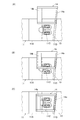
次に、図5を用いて、上記実施形態の分岐器用レール締結装置10により基本レールを床板11に締結して固定する作業の手順について説明する。
レール締結装置10によって基本レールを締結する作業は、ファーストクリップ13がショルダー部11Cに装着されていない状態で開始する。なお、床板11はファーストクリップ12によって枕木20上に固定され、レール載置部11Aに基本レールが載置されているものとする。
Next, a procedure of an operation of fastening and fixing the basic rail to the
The operation of fastening the basic rail by the
この状態で、先ずレールブレス14を、図5(A)に示すように、開口14cのある側壁がショルダー部11Cに近接するようにしてレール締結部の側方に位置させてから、先端の押圧部14bをレールの側面の顎部と腹部とフランジで構成される凹部に挿入するとともに、下面後端の突出部14aの一部を床板11の上面のガイド溝11Dに係合させる。
続いてレールブレス14の開口14cがない方の側壁をハンマー等の工具で叩いて、図5(B)に示すように、レールブレス14を基本レールと平行な方向へ移動させる。
In this state, first, as shown in FIG. 5A, the
Subsequently, the side wall of the
このとき、突出部14aがガイド溝11Dに係合しているため、突出部14aがガイド溝11Dに沿ってスライドするようにして移動するとともに、ガイド溝11Dがレール載置部11Aすなわちレールに対して傾斜しているため、レールブレス14がクサビのように機能して基本レールに近づいて行く。その後、ハンマー等でさらにレールブレス14を叩いて押し込むと、ショルダー部11Cがレールブレス14の中央に位置する図5(C)の状態となる。
At this time, since the
次に、ファーストクリップ13の両腕部をショルダー部11C両側部の係合穴に係合させてから、ファーストクリップ13の後端をレールと直交する方向から脱着治具等を用いて移動させる。すると、ファーストクリップ13の先端が、レールブレス14前端の押圧部14bの底壁上面に当接し、さらに押し込むとファーストクリップ13の先端がレールブレス14の底壁を押圧し、レールブレス14を介して基本レールRの下部フランジを押さえ付けることで、基本レールRを床板11に弾性締結した図2及び図3の状態となる。
Next, after the both arms of the
以上、本発明の一実施形態について説明したが、本発明は上記実施形態に限定されるものではなく、種々の変更が可能である。例えば、上記実施形態では、レールブレス14の上端の高さが基本レールの顎部よりも高く頭頂面よりも低くなるように形成されていると説明したが、例えば60kgレールのような比較的高さの高い基本レールを締結する場合には、レールブレスの上端の高さが基本レールの顎部よりも低くても、充分な強度を保てる場合があるので、そのような場合にはレールブレス14の上端の高さは基本レールの顎部よりも低くても良い。
As mentioned above, although one Embodiment of this invention was described, this invention is not limited to the said Embodiment, Various changes are possible. For example, in the above-described embodiment, the height of the upper end of the
また、上記実施形態では、レールブレス14の一対の側壁のうち少なくとも一方の側壁に開口14cを設けているが、両側壁にそれぞれ同様な開口を設けても良い。このように、レールブレスの一対の側壁の両方に開口を設けると軽量化することができる。
また、上記実施形態では、線ばねとしてファーストクリップを用いたレール締結装置に適用したものについて説明したが、線ばねとしてパンドール等の他の形状のクリップ(線ばね)あるいは板ばねを用いたレール締結装置に適用することも可能である。
Further, in the above embodiment, the
Further, in the above-described embodiment, an example in which the present invention is applied to a rail fastening device using a first clip as a wire spring has been described. However, a rail using a clip (wire spring) of another shape such as Pandor or a leaf spring as the wire spring. It is also possible to apply to a fastening device.
さらに、上記実施形態では、レールブレス14の後端下部の突出部14aが係合するガイド溝11Dが、レールないしはレール載置部11Aのエッジに対して所定の角度を有している場合について説明したが、ガイド溝11Dはレール載置部11Aのエッジと平行であっても良い。また、床板11にガイド溝11Dを設ける代わりに、床板11の上面に突条部を形成し、レールブレス14の後端下面にこの突条部と係合するガイド溝を形成しても良い。
Further, in the above-described embodiment, a case is described in which the
11 床板
11A レール載置部
11B 摺動部
11C ショルダー(ばね保持部)
11D ガイド溝
12 床板固定用のファーストクリップ(ばね部材)
13 レール固定用のファーストクリップ(ばね部材)
14 レールブレス
14a 突出部
14b 押圧部
14c 開口
13 Fast clip (spring member) for rail fixing
14
Claims (5)
前記レール載置部に載置された基本レールの側面に接触した状態で前記床板に装着されるレールブレスと、
前記ばね保持部に係合され前記レールブレスを介して前記基本レールの下部フランジを前記床板へ向かって押圧するばね部材と、
を備えたレール締結装置であって、
前記床板の前記ばね保持部よりも外側の所定位置には前記レール載置部と平行もしくは所定角度をなすガイド溝が形成され、
前記レールブレスは、前記ばね保持部との干渉を回避するための凹部を有し、先端に前記基本レールの顎部から腹部および下部フランジの一部かけての形状と対応する形状を有する押圧部を有し、下面後端には下方へ向けて突出し前記ガイド溝に係合可能な突出部が設けられ、前記押圧部と前記突出部との間に設けられた一対の側壁のうち少なくとも一方の側壁には、下部が解放され前記床板上に載置された状態で前記ばね保持部の側面視した形状よりも大きな形状をなす開口が形成されていることを特徴とするレール締結装置。 A sliding portion on which the tongue rail can slide, a rail mounting portion formed at a lower position than the sliding portion and on which a basic rail is mounted, and a sliding portion opposite to the sliding portion across the rail mounting portion. A floor plate having a spring holding portion provided at a predetermined position on the side,
A rail brace mounted on the floor plate in a state in contact with a side surface of a basic rail mounted on the rail mounting portion,
A spring member that is engaged with the spring holding portion and presses a lower flange of the basic rail toward the floor plate via the rail brace;
A rail fastening device comprising:
A guide groove parallel to or at a predetermined angle with the rail mounting portion is formed at a predetermined position of the floor plate outside the spring holding portion,
The rail brace has a concave portion for avoiding interference with the spring holding portion, and a pressing portion having a shape corresponding to a shape from a jaw portion of the basic rail to a part of the abdomen and a lower flange at a tip. A protrusion protruding downward at the rear end of the lower surface and capable of engaging with the guide groove is provided, and at least one of a pair of side walls provided between the pressing portion and the protrusion A rail fastening device, wherein an opening is formed in a side wall of the spring holding portion, the opening having a larger shape than a side view of the spring holding portion when the lower portion is released and placed on the floor plate.
前記ガイド溝および該ガイド溝に係合する前記レールブレスの前記突出部は、前記開口から遠い側ほどレールから離れ前記レール載置部と所定の角度をなすように形成されていることを特徴とする請求項1〜3の何れか一項に記載のレール締結装置。 The rail brace has the opening formed only on one of the pair of side walls,
The guide groove and the protruding portion of the rail brace that engages with the guide groove are formed so that the farther away from the opening is, the farther the rail is from the rail and the predetermined angle is formed with the rail mounting portion. The rail fastening device according to claim 1.
Priority Applications (1)
| Application Number | Priority Date | Filing Date | Title |
|---|---|---|---|
| JP2018129593A JP7051622B2 (en) | 2018-07-09 | 2018-07-09 | Rail fastening device |
Applications Claiming Priority (1)
| Application Number | Priority Date | Filing Date | Title |
|---|---|---|---|
| JP2018129593A JP7051622B2 (en) | 2018-07-09 | 2018-07-09 | Rail fastening device |
Publications (2)
| Publication Number | Publication Date |
|---|---|
| JP2020007783A true JP2020007783A (en) | 2020-01-16 |
| JP7051622B2 JP7051622B2 (en) | 2022-04-11 |
Family
ID=69151116
Family Applications (1)
| Application Number | Title | Priority Date | Filing Date |
|---|---|---|---|
| JP2018129593A Active JP7051622B2 (en) | 2018-07-09 | 2018-07-09 | Rail fastening device |
Country Status (1)
| Country | Link |
|---|---|
| JP (1) | JP7051622B2 (en) |
Citations (6)
| Publication number | Priority date | Publication date | Assignee | Title |
|---|---|---|---|---|
| JPS5331705U (en) * | 1976-08-24 | 1978-03-18 | ||
| JPH0318202U (en) * | 1989-02-03 | 1991-02-22 | ||
| JPH07247502A (en) * | 1994-03-11 | 1995-09-26 | Daiwa Kogyo Kk | Elastic fastening structure for turnout |
| JPH11303001A (en) * | 1998-04-24 | 1999-11-02 | Yamato Kogyo Co Ltd | Screwless nail elastic fastening device for rail |
| US6517008B1 (en) * | 2001-08-29 | 2003-02-11 | Cleveland Track Material, Inc. | Boltless adjustable rail brace assembly with external vertical restraint |
| JP3866570B2 (en) * | 2001-12-26 | 2007-01-10 | 東日本旅客鉄道株式会社 | Elastic fastening device for rails subjected to lateral pressure |
-
2018
- 2018-07-09 JP JP2018129593A patent/JP7051622B2/en active Active
Patent Citations (6)
| Publication number | Priority date | Publication date | Assignee | Title |
|---|---|---|---|---|
| JPS5331705U (en) * | 1976-08-24 | 1978-03-18 | ||
| JPH0318202U (en) * | 1989-02-03 | 1991-02-22 | ||
| JPH07247502A (en) * | 1994-03-11 | 1995-09-26 | Daiwa Kogyo Kk | Elastic fastening structure for turnout |
| JPH11303001A (en) * | 1998-04-24 | 1999-11-02 | Yamato Kogyo Co Ltd | Screwless nail elastic fastening device for rail |
| US6517008B1 (en) * | 2001-08-29 | 2003-02-11 | Cleveland Track Material, Inc. | Boltless adjustable rail brace assembly with external vertical restraint |
| JP3866570B2 (en) * | 2001-12-26 | 2007-01-10 | 東日本旅客鉄道株式会社 | Elastic fastening device for rails subjected to lateral pressure |
Also Published As
| Publication number | Publication date |
|---|---|
| JP7051622B2 (en) | 2022-04-11 |
Similar Documents
| Publication | Publication Date | Title |
|---|---|---|
| EP2166151A3 (en) | A safety device for a rail | |
| JP4602329B2 (en) | Elevator rail mounting device | |
| CA2529234A1 (en) | Anti-climbing device for railway carriages | |
| JP7051622B2 (en) | Rail fastening device | |
| JP6706842B2 (en) | Rail fastening device | |
| CN111164039B (en) | Elevator guide rail fixing device | |
| JP3081826B2 (en) | Screwless nail elastic fastening device for rail | |
| CN110462135A (en) | Track Fixing System | |
| JPH06239560A (en) | Guide rail supporting device | |
| JP3866570B2 (en) | Elastic fastening device for rails subjected to lateral pressure | |
| JPH072454A (en) | Guide rail holding device | |
| JP7625120B1 (en) | Elevator installation template device | |
| KR101067836B1 (en) | Lateral pressure reducing device and sleeper fastening structure and method using the same | |
| JP2020176511A (en) | Wedge binding device on scaffolding | |
| JP3764735B2 (en) | Opening and closing body device and hanging device used in the opening and closing body device | |
| JP7409534B1 (en) | Elevator guide rail fixing device | |
| JP7359326B1 (en) | Installation adjustment tool and installation method for position detection device | |
| JP2015098732A (en) | Rail fastening device for turnout | |
| JPH1025701A (en) | Rail fastening device having height adjusting function | |
| CN112064496B (en) | Longitudinal beam buckling device and track mechanism | |
| JPS63161201A (en) | Clamp member and rail clamping assembly | |
| KR200300583Y1 (en) | Doors for upper moving roller structure | |
| TW202517191A (en) | Slide rail positioning device | |
| JPH0560130A (en) | Linear motion rolling guide unit stopper | |
| GB2102478A (en) | A spring clip or securing a bullhead railway rail |
Legal Events
| Date | Code | Title | Description |
|---|---|---|---|
| A621 | Written request for application examination |
Free format text: JAPANESE INTERMEDIATE CODE: A621 Effective date: 20210517 |
|
| A977 | Report on retrieval |
Free format text: JAPANESE INTERMEDIATE CODE: A971007 Effective date: 20220317 |
|
| TRDD | Decision of grant or rejection written | ||
| A01 | Written decision to grant a patent or to grant a registration (utility model) |
Free format text: JAPANESE INTERMEDIATE CODE: A01 Effective date: 20220329 |
|
| A61 | First payment of annual fees (during grant procedure) |
Free format text: JAPANESE INTERMEDIATE CODE: A61 Effective date: 20220330 |
|
| R150 | Certificate of patent or registration of utility model |
Ref document number: 7051622 Country of ref document: JP Free format text: JAPANESE INTERMEDIATE CODE: R150 |
|
| R250 | Receipt of annual fees |
Free format text: JAPANESE INTERMEDIATE CODE: R250 |
|
| R250 | Receipt of annual fees |
Free format text: JAPANESE INTERMEDIATE CODE: R250 |