JP2020007877A - Piping member - Google Patents
Piping member Download PDFInfo
- Publication number
- JP2020007877A JP2020007877A JP2018132428A JP2018132428A JP2020007877A JP 2020007877 A JP2020007877 A JP 2020007877A JP 2018132428 A JP2018132428 A JP 2018132428A JP 2018132428 A JP2018132428 A JP 2018132428A JP 2020007877 A JP2020007877 A JP 2020007877A
- Authority
- JP
- Japan
- Prior art keywords
- flow path
- path switching
- peripheral wall
- wall portion
- switching member
- Prior art date
- Legal status (The legal status is an assumption and is not a legal conclusion. Google has not performed a legal analysis and makes no representation as to the accuracy of the status listed.)
- Granted
Links
Images


Classifications
-
- Y—GENERAL TAGGING OF NEW TECHNOLOGICAL DEVELOPMENTS; GENERAL TAGGING OF CROSS-SECTIONAL TECHNOLOGIES SPANNING OVER SEVERAL SECTIONS OF THE IPC; TECHNICAL SUBJECTS COVERED BY FORMER USPC CROSS-REFERENCE ART COLLECTIONS [XRACs] AND DIGESTS
- Y02—TECHNOLOGIES OR APPLICATIONS FOR MITIGATION OR ADAPTATION AGAINST CLIMATE CHANGE
- Y02E—REDUCTION OF GREENHOUSE GAS [GHG] EMISSIONS, RELATED TO ENERGY GENERATION, TRANSMISSION OR DISTRIBUTION
- Y02E30/00—Energy generation of nuclear origin
Landscapes
- Sewage (AREA)
Abstract
【課題】本体と流路切替部材とを備えた配管部材において、切り替え後の流路切替部材の位置を間違え難くすることができる。【解決手段】配管部材1は、流入口13、第1流出口11および第2流出口12が形成され、所定の方向に延びた周壁部15と、周壁部15の所定の方向側に設けられ、所定の方向に向かって開口する点検口19が形成された点検筒部20とを有する本体5と、本体5内に配置される流路切替部材35と、確認部37aを備える。流路切替部材35は、流入口13と第1流出口11とを連通させる第1位置P1と、流入口13と第2流出口12とを連通させる第2位置P2に配置可能である。確認部37aは、第1位置P1のときに第1確認位置に配置され、第2位置P2のときに第1確認位置とは位置が異なる第2確認位置に配置され、点検口19を通じて視認される。【選択図】図3PROBLEM TO BE SOLVED: To make it difficult to make a mistake in the position of a flow path switching member after switching in a piping member including a main body and a flow path switching member. SOLUTION: A piping member 1 is provided with a peripheral wall portion 15 having an inflow port 13, a first outlet 11 and a second outlet 12 formed thereof and extending in a predetermined direction, and a peripheral wall portion 15 on a predetermined direction side. A main body 5 having an inspection cylinder portion 20 formed with an inspection port 19 that opens in a predetermined direction, a flow path switching member 35 arranged in the main body 5, and a confirmation portion 37a are provided. The flow path switching member 35 can be arranged at the first position P1 that communicates the inlet 13 and the first outlet 11, and the second position P2 that communicates the inlet 13 and the second outlet 12. The confirmation unit 37a is arranged at the first confirmation position at the first position P1 and at the second confirmation position different from the first confirmation position at the second position P2, and is visually recognized through the inspection port 19. To. [Selection diagram] Fig. 3
Description
本発明は、排水の流路を切り替えることができる配管部材(例えば、排水ます、管継手など)に関する。 The present invention relates to a pipe member (for example, a drain basin, a pipe joint, etc.) capable of switching a flow path of drain water.
特許文献1には、流路を切り替えることが可能な排水ますが記載されている。特許文献1に記載された排水ますは、ます本体と、ます本体内に配置され、上下に延びた中心軸を中心に回動可能な流路切替部材とを備えている。ます本体は、側方に開口する流入口、第1流出口および第2流出口と、上方に開口する点検口とを有している。流路切替部材には、連通路が形成されている。流路切替部材は、連通路を通じて流入口と第1流出口を連通させ、かつ、第2流出口を閉鎖する第1位置と、連通路を通じて流入口と第2流出口を連通させ、かつ、第1流出口を閉鎖する第2位置とに位置変更が可能である。上記排水ますは、流路切替部材の位置を変更することで流路を切り替えることができる。
ところで、上記排水ますでは、流路を切り替えるとき、切り替え後の流路切替部材の位置の候補が複数存在する。例えば、流路切替部材が第1位置に配置されている状態で流路を切り替える場合、切り替え後の流路切替部材の位置の候補として、第2流出口を閉鎖する位置(第2位置)と、流入口を閉鎖する位置とが存在する。このような場合、流路切替部材を第2位置に配置しなければならないにも関わらず、流入口を閉鎖するような位置に流路切替部材を配置するおそれがあり、切り替え後の流路切替部材の位置を間違えるおそれがあった。 By the way, in the drainage system, when switching the flow path, there are a plurality of candidates for the position of the flow path switching member after the switching. For example, when switching the flow path in a state where the flow path switching member is disposed at the first position, the position (second position) at which the second outlet is closed is set as a candidate for the position of the flow path switching member after the switching. And a position for closing the inlet. In such a case, there is a possibility that the flow path switching member may be disposed at a position that closes the inflow port, although the flow path switching member must be disposed at the second position. There was a possibility that the position of the member was mistaken.
本発明はかかる点に鑑みてなされたものであり、その目的は、本体と流路切替部材とを備えた配管部材において、切り替え後の流路切替部材の位置を間違え難くすることが可能な配管部材を提供することである。 The present invention has been made in view of such a point, and an object of the present invention is to provide a piping member having a main body and a flow path switching member, in which the position of the flow path switching member after switching can be made hard to be mistaken. It is to provide a member.
本発明者は、切り替え後の流路切替部材の位置を間違える原因について、種々検討した。その結果、作業者が切り替え前の流路切替部材の位置を適切に把握していないときに、切り替え後の流路切替部材の位置を間違える可能性があることを発見した。例えば、上記排水ますでは、第1位置に配置されている流路切替部材を反時計回りに所定の角度(例えば120度)回転させることで、第2位置に配置させることができ、第2位置に配置されている流路切替部材を時計回りに所定の角度回転させることで、第1位置に配置させることができる。ここで、切り替え前の流路切替部材の位置が第1位置にも関わらず、作業者が第2位置に配置されていると誤認識している場合、流路を切り替えるために流路切替部材を時計回りに所定の角度回転させることがあり得る。その結果、流入口を閉鎖する位置に流路切替部材が配置され、切り替え後の流路切替部材の位置を間違える。以上のことから、本発明者は、作業者が切り替え前の流路切替部材の位置を適切に把握することで、切り替え後の流路切替部材の位置を間違え難くすることができることを見出した。 The present inventor has made various investigations on the cause of incorrectly positioning the flow path switching member after switching. As a result, it has been found that when the operator does not properly grasp the position of the flow path switching member before switching, there is a possibility that the position of the flow path switching member after switching may be mistaken. For example, in the drainage trough, the flow path switching member disposed at the first position is rotated counterclockwise by a predetermined angle (for example, 120 degrees), thereby being disposed at the second position. By rotating the flow path switching member disposed at a predetermined angle clockwise, it can be disposed at the first position. Here, when the position of the flow path switching member before switching is erroneously recognized as being located at the second position despite the first position, the flow path switching member is used to switch the flow path. May be rotated clockwise by a predetermined angle. As a result, the flow path switching member is disposed at a position where the flow inlet is closed, and the position of the flow path switching member after switching is erroneously set. From the above, the present inventor has found that it is possible for the operator to properly grasp the position of the flow path switching member before switching, thereby making it difficult to mistake the position of the flow path switching member after switching.
本発明に係る配管部材は、本体と、流路切替部材と、確認部とを備えている。前記本体は、流入口、第1流出口および第2流出口が形成され、所定の方向に延びた周壁部と、前記周壁部の前記所定の方向側に設けられ、前記所定の方向に向かって開口する点検口が形成された点検筒部と、を有している。前記流路切替部材は、第1開口および第2開口が形成された側壁部と、前記第1開口と前記第2開口とを繋ぐインバートが形成された底壁部と、を有している。前記流路切替部材は、前記本体に対して、前記第1開口と前記流入口とが重なり、かつ、前記第2開口と前記第1流出口とが重なる第1位置と、前記第2開口と前記流入口とが重なり、かつ、前記第1開口と前記第2流出口とが重なる第2位置とに配置可能に構成されている。前記確認部は、前記流路切替部材が前記第1位置に配置されているときに第1確認位置に配置され、前記流路切替部材が前記第2位置に配置されているときに前記第1確認位置とは位置が異なる第2確認位置に配置され、前記流路切替部材が前記第1位置に配置されているとき、および、前記第2位置に配置されているときに前記本体の前記点検口を通じて視認される。 A piping member according to the present invention includes a main body, a flow path switching member, and a confirmation unit. The main body has an inflow port, a first outflow port, and a second outflow port, a peripheral wall portion extending in a predetermined direction, and provided on the side of the peripheral wall portion in the predetermined direction. And an inspection cylinder portion having an inspection port that opens. The flow path switching member has a side wall having a first opening and a second opening, and a bottom wall having an invert connecting the first opening and the second opening. The flow path switching member is configured such that, with respect to the main body, the first opening and the inflow port overlap with each other, and the second opening and the first outflow port overlap with each other; The inlet is overlapped with the first opening and the second outlet is arranged at a second position where the outlet overlaps. The confirmation unit is disposed at a first confirmation position when the flow path switching member is disposed at the first position, and is disposed at a first position when the flow path switching member is disposed at the second position. The inspection of the main body is arranged at a second confirmation position different from the confirmation position, when the flow path switching member is arranged at the first position, and when the flow path switching member is arranged at the second position. Viewed through mouth.
上記配管部材によれば、流路を切り替える際、作業者は、点検口を通じて確認部の位置を確認することで、流路を切り替える前の流路切替部材の位置を確認することができる。例えば確認部が第1確認位置に配置されているとき、流路切替部材が第1位置に配置されていることを確認することができる。よって、作業者は、流路切替部材の位置を第1位置から第2位置に変更することを事前に把握することができる。また、例えば確認部が第2確認位置に配置されているとき、流路切替部材が第2位置に配置されていることを確認することができる。よって、作業者は、流路切替部材の位置を第2位置から第1位置に変更することを事前に把握することができる。このように、切り替え前の流路切替部材の位置を確認することで、流路の切り替え先を間違え難くすることができる。 According to the piping member, when switching the flow path, the operator can confirm the position of the flow path switching member before switching the flow path by checking the position of the checking unit through the inspection port. For example, when the confirmation section is located at the first confirmation position, it can be confirmed that the flow path switching member is located at the first position. Therefore, the operator can grasp in advance that the position of the flow path switching member is to be changed from the first position to the second position. In addition, for example, when the confirmation unit is disposed at the second confirmation position, it can be confirmed that the flow path switching member is disposed at the second position. Therefore, the operator can grasp in advance that the position of the flow path switching member is to be changed from the second position to the first position. As described above, by confirming the position of the flow path switching member before switching, it is possible to make it difficult to mistake the switching destination of the flow path.
本発明の好ましい一態様によれば、前記側壁部は、前記第1開口が形成された第1側壁部と、前記第2開口が形成された第2側壁部と、前記流路切替部材が前記第1位置に配置されているときに前記本体の前記第2流出口と対向し、前記流路切替部材が前記第2位置に配置されているときに前記本体の前記第1流出口と対向するように配置される側壁閉鎖部と、を有している。 According to a preferred aspect of the present invention, the side wall portion includes a first side wall portion in which the first opening is formed, a second side wall portion in which the second opening is formed, and the flow path switching member. When it is located at the first position, it faces the second outlet of the main body, and when it is located at the second position, it faces the first outlet of the main body. And a side wall closure arranged in such a manner.
上記態様によれば、流路切替部材の側壁部の側壁閉鎖部が第2流出口と対向するように、流路切替部材を本体に対して配置することで、流路切替部材を第1位置に適切に配置することができる。また、流路切替部材の側壁閉鎖部が第1流出口と対向するように、流路切替部材を本体に対して配置することで、流路切替部材を第2位置に適切に配置することができる。 According to the above aspect, the flow path switching member is disposed with respect to the main body such that the side wall closing portion of the side wall portion of the flow path switching member faces the second outlet, so that the flow path switching member is in the first position. Can be properly arranged. Further, by disposing the flow path switching member with respect to the main body such that the side wall closing portion of the flow path switching member faces the first outlet, the flow path switching member can be appropriately disposed at the second position. it can.
本発明の好ましい他の一態様によれば、前記配管部材は、前記側壁閉鎖部と前記本体の前記周壁部との間に配置された閉鎖部材を備えている。前記閉鎖部材の少なくとも前記点検口と対向する対向面には、前記対向面の周囲とは異なる色が付されている。前記確認部は、前記閉鎖部材の少なくとも前記対向面によって構成されている。 According to another preferred aspect of the present invention, the piping member includes a closing member disposed between the side wall closing portion and the peripheral wall portion of the main body. At least the facing surface of the closing member facing the inspection port is colored differently from the periphery of the facing surface. The confirmation unit is constituted by at least the opposed surface of the closing member.
上記態様によれば、閉鎖部材は、流路器切替部材が第1位置に配置されたときに第2流出口と対向する位置に配置され、第2位置に配置されたときに第1流出口と対向する位置に配置される。そのため、閉鎖部材の位置を確認することによって、流路を切り替える前の流路切替部材の位置を事前に確認することができる。上記態様では、閉鎖部材の少なくとも上面には、当該上面の周囲と異なる色が付されているため、閉鎖部材の位置を視認し易い。よって、流路を切り替える前の流路切替部材の位置を確認し易い。 According to the above aspect, the closing member is disposed at the position facing the second outlet when the flow path switching member is disposed at the first position, and is disposed at the first outlet when disposed at the second position. Is disposed at a position opposite to. Therefore, by confirming the position of the closing member, the position of the passage switching member before switching the passage can be confirmed in advance. In the above aspect, at least the upper surface of the closing member is colored differently from the periphery of the upper surface, so that the position of the closing member can be easily visually recognized. Therefore, it is easy to confirm the position of the flow path switching member before switching the flow path.
本発明の好ましい他の一態様によれば、前記確認部は、平面視において前記側壁閉鎖部から前記流路切替部材の中心とは反対側に向かって突出した突出部によって構成されている。 According to another preferred aspect of the present invention, the confirmation portion is configured by a protrusion protruding from the side wall closing portion toward a side opposite to a center of the flow path switching member in a plan view.
上記態様によれば、突出部は、流路器切替部材が第1位置に配置されたときに第2流出口の上方に配置され、第2位置に配置されたときに第1流出口の上方に配置される。よって、突出部の位置を確認することによって、流路を切り替える前の流路切替部材の位置を確認することができる。 According to the above aspect, the protrusion is disposed above the second outlet when the flow path switching member is disposed at the first position, and is disposed above the first outlet when disposed at the second position. Placed in Therefore, by checking the position of the protruding portion, the position of the flow path switching member before switching the flow path can be checked.
本発明の好ましい他の一態様によれば、前記周壁部は、前記第1流出口が形成された第1周壁部と、前記第2流出口が形成された第2周壁部と、前記流入口が形成された第3周壁部と、を有している。前記第1周壁部には、前記流路切替部材が前記第2位置に配置されたときに前記突出部と係合する第1係合部が設けられている。前記第2周壁部には、前記流路切替部材が前記第1位置に配置されたときに前記突出部と係合する第2係合部が設けられている。前記第3周壁部には、前記突出部と係合する部分が設けられていない。 According to another preferred aspect of the present invention, the peripheral wall portion includes a first peripheral wall portion where the first outlet is formed, a second peripheral wall portion where the second outlet is formed, and the inlet. And a third peripheral wall portion formed with the second peripheral wall portion. The first peripheral wall is provided with a first engaging portion that engages with the protruding portion when the flow path switching member is disposed at the second position. The second peripheral wall is provided with a second engaging portion that engages with the protruding portion when the flow path switching member is disposed at the first position. The third peripheral wall portion is not provided with a portion that engages with the protrusion.
上記態様によれば、突出部と、ます本体の周壁部の第2周壁部に設けられた第2係合部とを係合させることで、流路切替部材を第1位置に適切に配置することができる。また、突出部と、本体の第1周壁部に設けられた第1係合部とを係合させることで、流路切替部材を第2位置に適切に配置することができる。なお、流入口が形成されている第3周壁部には、突出部と係合する部分が設けられていない。よって、流入口が閉鎖される位置に流路切替部材を配置することはできない。したがって、流入口が閉鎖される位置に流路切替部材が誤って配置されることを防止することができる。 According to the above aspect, the flow path switching member is appropriately arranged at the first position by engaging the projecting portion with the second engaging portion provided on the second peripheral wall of the peripheral wall of the main body. be able to. In addition, by engaging the projecting portion with the first engaging portion provided on the first peripheral wall portion of the main body, the flow path switching member can be appropriately arranged at the second position. In addition, the part which engages with a protrusion part is not provided in the 3rd peripheral wall part in which the inflow port is formed. Therefore, the flow path switching member cannot be arranged at a position where the inflow port is closed. Therefore, it is possible to prevent the flow path switching member from being erroneously arranged at a position where the inflow port is closed.
本発明の好ましい他の一態様によれば、前記配管部材は、前記流路切替部材の前記側壁部に架け渡された取っ手を備えている。前記確認部は、前記取っ手に付され、前記側壁閉鎖部の位置を示す目印によって構成されている。 According to another preferred aspect of the present invention, the pipe member includes a handle that is bridged over the side wall of the flow path switching member. The confirmation portion is formed by a mark attached to the handle and indicating a position of the side wall closing portion.
上記態様によれば、作業者は、取っ手に付された目印を視認することで、側壁閉鎖部の位置を確認することができる。よって、この目印を視認することで、流路を切り替える前の流路切替部材の位置を事前に確認することができる。 According to the above aspect, the operator can confirm the position of the side wall closing portion by visually recognizing the mark on the handle. Therefore, by visually recognizing this mark, the position of the flow path switching member before switching the flow path can be confirmed in advance.
本発明の好ましい他の一態様によれば、前記配管部材は、前記流路切替部材の前記側壁部に架け渡され、一端が前記側壁閉鎖部に設けられた取っ手を備えている。前記取っ手は、前記取っ手の軸方向で前記取っ手を2分割したときの前記一端側に配置された第1取っ手部と、前記取っ手の軸方向で前記取っ手を2分割したときの前記一端とは反対の他端側に配置された第2取っ手部と、を有している。前記第1取っ手部と前記第2取っ手部とは非対称の形状を有している。前記確認部は、前記取っ手によって構成されている。 According to another preferred aspect of the present invention, the pipe member is provided with a handle that is bridged over the side wall portion of the flow path switching member and has one end provided in the side wall closing portion. The handle has a first handle portion disposed on the one end side when the handle is divided into two in the axial direction of the handle, and the first end when the handle is divided into two in the axial direction of the handle. And a second handle portion disposed at the other end of the second handle. The first handle and the second handle have asymmetric shapes. The confirmation unit is configured by the handle.
上記態様によれば、取っ手の第1取っ手部と第2取っ手部とは非対称の形状を有しているため、取っ手を視認することで、第1取っ手部の位置から側壁閉鎖部が配置された位置を確認することができる。よって、作業者が取っ手を視認することで、流路を切り替える前の流路切替部材の位置を確認することができる。 According to the above aspect, since the first handle portion and the second handle portion of the handle have an asymmetric shape, the side wall closing portion is arranged from the position of the first handle portion by visually recognizing the handle. You can check the position. Therefore, by visually recognizing the handle, the position of the flow path switching member before switching the flow path can be confirmed.
本発明の好ましい他の一態様によれば、前記インバートは、前記所定の方向から見たときに前記側壁閉鎖部側に凹んだ曲部を有している。前記確認部は、前記曲部によって構成されている。 According to another preferred aspect of the present invention, the invert has a curved portion that is concave toward the side wall closing portion when viewed from the predetermined direction. The confirmation section is configured by the music section.
上記態様によれば、作業者は、インバートの曲部を視認することで、側壁閉鎖部の位置を確認することができる。よって、インバートの曲部を視認することで、流路を切り替える前の流路切替部材の位置を事前に確認することができる。 According to the above aspect, the worker can confirm the position of the side wall closing portion by visually recognizing the curved portion of the invert. Therefore, by visually recognizing the curved portion of the invert, the position of the flow path switching member before switching the flow path can be confirmed in advance.
本発明の好ましい他の一態様によれば、前記本体は、前記周壁部と前記点検筒部とに連結され、前記所定の方向から見たときに前記本体の前記点検口を通じて視認される視認部を有している。前記周壁部は、前記第1流出口が形成された第1周壁部と、前記第2流出口が形成された第2周壁部と、前記流入口が形成された第3周壁部と、を有している。前記視認部は、前記第1周壁部に連結された第1視認部と、前記第2周壁部に連結された第2視認部と、前記第3周壁部に連結された第3視認部と、を有している。前記第1視認部および前記第2視認部には、排水が前記本体から流出することを示す流出目印が付されている。前記第3視認部には、排水が前記本体に流入することを示す流入目印が付されている。 According to another preferred aspect of the present invention, the main body is connected to the peripheral wall portion and the inspection tube portion, and is a visible portion that is visually recognized through the inspection port of the main body when viewed from the predetermined direction. have. The peripheral wall has a first peripheral wall on which the first outlet is formed, a second peripheral wall on which the second outlet is formed, and a third peripheral wall on which the inlet is formed. are doing. A first viewing portion connected to the first peripheral wall portion, a second viewing portion connected to the second peripheral wall portion, a third viewing portion connected to the third peripheral wall portion, have. The first visual recognition unit and the second visual recognition unit are provided with outflow marks indicating that drainage flows out of the main body. The third visual recognition section is provided with an inflow mark indicating that the drainage flows into the main body.
上記態様によれば、流出目印を視認することで、第1流出口および第2流出口の位置を確認することができ、流入目印を視認することで、流入口の位置を確認することができる。よって、流入口、第1流出口および第2流出口の位置を確認することができるため、作業者は、流入口を閉鎖するような位置に流路切替部材を配置しないようにすることができる。 According to the above aspect, the position of the first outlet and the second outlet can be confirmed by visually checking the outflow mark, and the position of the inlet can be confirmed by visually recognizing the inflow mark. . Therefore, since the positions of the inflow port, the first outflow port, and the second outflow port can be confirmed, the operator can prevent the flow path switching member from being disposed at a position that closes the inflow port. .
本発明によれば、本体と流路切替部材とを備えた配管部材において、切り替え後の流路切替部材の位置を間違え難くすることができる。 ADVANTAGE OF THE INVENTION According to this invention, in the piping member provided with the main body and the flow path switching member, the position of the flow path switching member after switching can be made hard to be mistaken.
以下、図面を参照しながら、本発明の実施形態に係る配管部材の一例である排水ますについて説明する。ただし、以下に説明する実施形態は、本発明の実施形態に過ぎず、当然ながら本発明を限定することを意図したものではない。 Hereinafter, a drainage trough as an example of a piping member according to an embodiment of the present invention will be described with reference to the drawings. However, the embodiment described below is merely an embodiment of the present invention, and is not intended to limit the present invention.
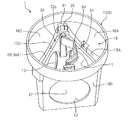
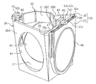
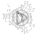
図1は、本発明の一実施形態に係る排水ます1の斜視図である。図2、図3は、ぞれぞれ排水ます1の一部を示す斜視図、平面図である。図4は、図3のIV−IV線に沿った断面図である。排水ます1は、排水の流路を切り替えることが可能なますであり、地中に埋設されている。排水ます1は、図1に示すように、ます本体5と、ます本体5の後述する点検口19を塞ぐ蓋16とを備えている。ます本体5は、図2に示す主要部10と、3つの横筒部21、22、23(図3参照)と、点検筒部20(図1参照)とを有している。なお、図2等では、排水ます1の構造上の特徴が分かりやすいように、ます本体5に関しては主要部10のみを切り出して図示している。しかし実際には、主要部10と横筒部21、22、23と点検筒部20とは、樹脂材料により一体的に形成されている。図2に示すように、排水ます1は、さらにます本体5に着脱自在に装着される流路切替部材35と、流路切替部材35の着脱の際に作業者によって掴まれる取っ手50とを備えている。
FIG. 1 is a perspective view of a
まず、ます本体5について説明する。図4に示すように、ます本体5は、底壁部14と、底壁部14から起立した周壁部15と、周壁部15の上部に設けられた傾斜部16と、を備えている。図示は省略するが、底壁部14は、略三角形状を有している。周壁部15は、図3に示すように、平面視において略三角形状になるように配置された第1周壁部15A、第2周壁部15Bおよび第3周壁部15Cを有している。なお、本実施形態では、上方は、本発明の「所定の方向」に対応している。図4に示すように、第2周壁部15Bは、下方に向かうほど底壁部14の中心に近づくように、鉛直線から傾いている。詳しい図示は省略するが、第1周壁部15Aおよび第3周壁部15Cも同様に、下方に向かうほど底壁部14の中心に近づくように鉛直線から傾いている。換言すると、第1周壁部15A、第2周壁部15Bおよび第3周壁部15Cは、上方に向かうほど互いに離反するように鉛直線から傾いている。
First, the
図2に示すように、第1周壁部15Aには第1流出口11が形成され、第2周壁部15Bには第2流出口12が形成されている。また、第3周壁部15Cには流入口13が形成されている。流入口13、第1流出口11および第2流出口12は、それぞれ内径が等しく、側方に向かって開口している。
As shown in FIG. 2, a
図3に示すように、第1周壁部15Aと第3連結部15Cとの交差部分の上部には、第1連結部61が設けられている。第2周壁部15Bの上部には、第2連結部62が設けられている。第2周壁部15bと第3周壁部15Cとの交差部分の上部には、第3連結部63が設けられている。第1周壁部15Aの上部には、第4連結部64が設けられている。これら第1〜第4連結部61〜64には、それぞれ係合孔30が形成されている。第1連結部61の係合孔30と、第2連結部62の係合孔30とは、平面視においてます本体5の中心5cを挟んで互いに向かい合っている。第3連結部63の係合孔30と、第4連結部64の係合孔30とは、平面視においてます本体5の中心5cを挟んで互いに向かい合っている。本実施形態では、第3周壁部15C、および、第1周壁部15Aと第2周壁部15Bとの交差部分には、上述のような連結部が設けられておらず、係合孔30は形成されていない。本実施形態では、第4連結部64の係合孔30は、本発明の「第1係合部」に対応し、第2連結部62の係合孔30は、本発明の「第2係合部」に対応している。なお、以下の説明では、ます本体5の中心5cに近づく方向を内方と称し、ます本体5の中心5c(または流路切替部材35の中心)から遠ざかる方向を外方と称する。
As shown in FIG. 3, a
本実施形態では、連結部61〜64は第1周壁部15A〜第3周壁部15Cとは別部材であり、第1周壁部15A〜第3周壁部15Cに組み付けられている。しかしながら、連結部61〜64と第1周壁部15A〜第3周壁部15Cとは、単一の部材であってもよい。なお、図2では、第4連結部64の図示は省略されている。
In the present embodiment, the connecting
傾斜部16は、ます本体5の点検口19を通じて視認することが可能な部分である。傾斜部16は、周壁部15と点検筒部20とに連結されている。傾斜部16は、図4に示すように、周壁部15の上端から上方に向かうに連れて、ます本体5の外方に向かって斜めに延びている。換言すると、傾斜部16は、下方に向かうに連れてます本体5の内方に向かって傾斜している。傾斜部16は、図3に示すように、第1傾斜部16A、第2傾斜部16Bおよび第3傾斜部16Cを有している。図2に示すように、第1傾斜部16Aは、第1周壁部15Aの上端に連結され、第1流出口11の上方に配置されている。詳しい図示は省略するが、第2傾斜部16Bは、第2周壁部15Bの上端に連結され、第2流出口12の上方に配置されている。図2に示すように、第3傾斜部16Cは、第3周壁部15Cの上端に連結され、流入口13の上方に配置されている。なお、本実施形態では、傾斜部16、第1傾斜部16A、第2傾斜部16Bおよび第3傾斜部16Cは、それぞれ本発明の視認部、第1視認部、第2視認部および第3視認部に対応している。
The
ここでは、図3に示すように、第1傾斜部16Aには、下方に配置された第1流出口11から排水が流出することを示す流出目印17Aが付されている。第2傾斜部16Bには、下方に配置された第2流出口12から排水が流出することを示す流出目印17Bが付されている。これら流出目印17A、17Bは、ます本体5の内方から外方に向かって指し示す矢印である。また、第3傾斜部16Cには、下方に配置された流入口13に排水が流入することを示す流入目印17Cが付されている。この流入目印17Cは、ます本体5の外方から内方に向かって指し示す矢印である。なお、流出目印17A、17B、流入目印17Cの形状および矢印の向きは、特に限定されない。作業者は、点検筒部20の点検口19(図1参照)を通じて、流出目印17A、17Bおよび流入目印17Cを視認することが可能である。なお、図2において、流出目印17A、17Bおよび流入目印17Cの図示は省略されている。
Here, as shown in FIG. 3, the first
図1に示すように、横筒部21は、第1周壁部15Aから径方向の外方に向かって延びており、第1流出口11(図2参照)と連通している。いる。図3に示すように、横筒部21には第1流出管91が接続される。横筒部22は、第2周壁部15Bから径方向の外方に向かって延びており、第2流出口12(図2参照)と連通している。横筒部22には第2流出管92が接続される。横筒部23は第3周壁部15Cから径方向の外方に向かって延びており、流入口13(図2参照)と連通している。横筒部23には流入管93が接続される。
As shown in FIG. 1, the
図1に示すように、点検筒部20は主要部10の上方において、上下に延びている。図2に示すように、点検筒部20は、傾斜部16の上端に接続されている。点検筒部20は上方に開口しており、点検筒部20の開口が点検口19を構成している。図1に示すように、点検口19には、蓋16が着脱自在に嵌め込まれる。
As shown in FIG. 1, the
次に、流路切替部材35について説明する。流路切替部材35は、排水ます1の内部の排水の流路を区画すると共に、排水の流路の切り替えを可能にする部材である。図5は、流路切替部材35の斜視図である。図5に示すように、流路切替部材35は、流路部材38と、閉鎖部材37とを有している。
Next, the flow
流路部材38は、底壁部49(図4参照)と、側壁部36とを有している。図3に示すように、底壁部49は平面視において略三角形状を有している。側壁部36は、平面視において、略三角形状となるように配置された第1側壁部36A、第2側壁部36Bおよび側壁閉鎖部36Cを含んでいる。ます本体5の第1周壁部15A、第2周壁部15Bおよび第3周壁部15Cと同様に、第1側壁部36A、第2側壁部36Bおよび側壁閉鎖部36Cは、それぞれ下方に向かうほど底壁部49の中心に近づくように鉛直線から傾いている(図4参照)。換言すると、第1側壁部36A、第2側壁部36Bおよび側壁閉鎖部36Cは、それぞれ上方に向かうほど互いに離反するように鉛直線から傾斜している。
The
図5に示すように、第1側壁部36Aには第1開口41が形成され、第2側壁部36Bには第2開口42が形成されている。図4に示す底壁部49には、第1開口41と第2開口42とを繋ぐインバート57(図5参照)が形成されている。インバート57は、排水が流れる溝状の流路のことである。インバート57は、平面視において閉鎖部材37側に凹む曲部57aを有している。なお、側壁閉鎖部36Cには開口は形成されていない。
As shown in FIG. 5, a
図5に示すように、側壁閉鎖部36Cの外方の面の両側には、上下に延びるスライド溝39aが形成されたレール39が設けられている。第1側壁部36Aと第2側壁部36Bとの交差部分の上部と、側壁閉鎖部36Cの上部とには、貫通孔45が形成された連結部43が設けられている。
As shown in FIG. 5, rails 39 provided with
閉鎖部材37は、流路切替部材35がます本体5に装着されたときに第1流出口11または第2流出口12を閉鎖するための部材である。図5に示すように、閉鎖部材37には、環状のシール部材48が設けられている。シール部材48は、例えばゴムによって構成されており、可撓性を有している。シール部材48は、閉鎖部材37がます本体5の第1周壁部15A(図2参照)に押し付けられたときには、第1流出口11の周囲を封止する。シール部材48は、閉鎖部材37がます本体5の第2周壁部15B(図2参照)に押し付けられたときには、第2流出口12の周囲を封止する。
The closing
図5に示すように、閉鎖部材37は板状に形成されており、流路部材38の側壁閉鎖部36Cに対し上下にスライド可能に構成されている。図6は、閉鎖部材37の正面図である。図6に示すように、閉鎖部材37の両側には、流路部材38のレール39のスライド溝39a(図5参照)に係合する係合突起47が設けられている。図7は、閉鎖部材37の係合突起47およびレール39のスライド溝39aの断面図である。本実施形態では、図7に示すように、レール39のスライド溝39aの下端は閉じており、係合突起47がスライド溝39aの下端までスライドすると、係合突起47はレール39の下端部によって支持される。このことによって、係合突起47が下方に脱落することが防止される。そのため、流路部材38を持ち上げたときに、閉鎖部材37が流路部材38から脱落することが防止される(図8参照)。
As shown in FIG. 5, the closing
本実施形態では、図5に示すように、閉鎖部材37の上面37aには、上面37aの周囲とは異なる色が付されている。ここで、上面37aは、閉鎖部材37をます本体5内に配置したとき、点検口19(図1参照)と対向する面であり、本発明の「対向面」に対応する。例えば、閉鎖部材37の上面37aには、黄色が付されている。ただし、閉鎖部材37の上面37a以外の閉鎖部材37の部分に黄色が付されていてもよい。なお、図5等において、黄色が付された部分は、クロスハッチングによって表示されている。本実施形態では、ます本体5の全体、流路切替部材35の低壁部49および側壁部36、取っ手50には、灰色が付されている。なお、閉鎖部材37の少なくとも上面37aに付される色は、黄色に限定されず、例えば閉鎖部材37の周囲の部分(例えば、ます本体5の全体、流路切替部材35の低壁部49および側壁部36、取っ手50)と区分けし易い黄色以外の色が付されてもよい。本実施形態では、閉鎖部材37の上面37aが本発明の「確認部」に対応している。
In the present embodiment, as shown in FIG. 5, the
取っ手50は、流路切替部材35をます本体5から取り外すとき、および、ます本体5に装着するときに、作業者が掴む部分である。図5に示すように、取っ手50は、流路切替部材35の側壁部36に架け渡されている。詳しくは、取っ手50は、側壁部36の第1側壁部36Aと第2側壁部36Bとが交差部分の上部と、側壁閉鎖部36Cの上部とに、架け渡されている。
The
取っ手50は、把持部51と把持部51の両端部から延びる軸部52a、52bとを有している。把持部51の形状は特に限定されないが、例えば屈曲した板状に形成されている。軸部52a、52bは棒状に形成されている。本実施形態では、把持部51の一端部に設けられた軸部52aは、側壁閉鎖部36Cから流路切替部材35の外方に向かって突出しており、その突出した部分である突出部52cは、閉鎖部材37の上方に配置されている。本実施形態では、軸部52aの突出部52cは、本発明の「突出部」に対応している。また、把持部51の他端部に設けられた軸部52bは、側壁部36の第1側壁部36Aと第2側壁部36Bとが交差部分から流路切替部材35の外方に向かって突出している。本実施形態では、取っ手50は流路部材38に対して回動可能に構成されている。ここでは、軸部52a、52bは、流路切替部材35の連結部43の貫通孔45を貫通している。これにより、軸部52a、52bは連結部43に回動可能に連結されている。
The
なお、ます本体5、流路切替部材35(ただし、シール部材48を除く。)、および、取っ手50の材料は特に限定されないが、ここでは樹脂材料によって構成されている。
The materials of the
流路切替部材35は、第1位置P1(図3参照)と第2位置P2(図9参照)とに配置可能である。詳しい図示は省略するが、第1位置P1は、ます本体5の流入口13と第1流出口11とを繋ぐ位置である。第2位置P2は、ます本体5の流入口13と第2流出口12とを繋ぐ位置である。図3に示すように、第1位置P1では、流路切替部材35の側壁部36の側壁閉鎖部36C、および閉鎖部材37は、ます本体5の周壁部15の第2周壁部15Bと対向し、かつ、第2周壁部15Bに形成された第2流出口12(図2参照)と対向している。第1位置P1では、流路切替部材35の第1開口41はます本体5の流入口13と重なり、第2開口42は第1流出口11と重なり、第2流出口12は閉鎖部材37によって塞がれる。その結果、流入口13と第1流出口11とが連通し、流入口13から流入した排水は、第1流出口11から流出する。排水は、流入管93から排水ます1を経て第1流出管91に流れる。
The flow
図9に示す第2位置P2は、図3において流路切替部材35を反時計回りに120度回転させた位置である。図9に示すように、第2位置P2では、流路切替部材35の側壁閉鎖部36Cおよび閉鎖部材37は、ます本体5の第1周壁部15Aに対向し、かつ、第1周壁部15Aに形成された第1流出口11(図2参照)と対向している。第2位置P2では、流路切替部材35の第1開口41はます本体5の第2流出口12と重なり、第2開口42は流入口13と重なり、第1流出口11は閉鎖部材37によって塞がれる。その結果、流入口13と第2流出口12とが連通し、流入口13から流入した排水は、第2流出口12から流出する。排水は、流入管93から排水ます1を経て第2流出管92に流れる。このように、流路切替部材35の位置を変更することにより、排水ます1の流路を切り替えることができる。
The second position P2 shown in FIG. 9 is a position where the flow
次に、排水ます1の排水の流路を切り替える手順について説明する。ここでは、流路切替部材35の位置を第1位置P1から第2位置P2に変更する手順について説明する。
Next, a procedure for switching the flow path of the
上述の通り、図3は流路切替部材35が第1位置P1に配置されている状態を示している。流路切替部材35が第1位置P1に配置されているとき、取っ手50の軸部52aは、第2周壁部15Bに設けられた第2連結部62の係合孔30に係合し、軸部52bは、第1周壁部15Aと第3周壁部15Cの交差部分に設けられた第1連結部61の径合孔30に係合している。第1位置P1のとき、閉鎖部材37は第2周壁部15Bに形成された第2流出口12(図2参照)に対向しており、第2流出口12を閉鎖している。本実施形態では、第1位置P1において、閉鎖部材37が第2流出口12に対向するように配置された位置が、本発明の「第1確認位置」に対応している。上述のように、閉鎖部材37の上面37aの色が黄色であるため、作業者は、閉鎖部材37の上面37aを点検口19(図1参照)から視認することで、閉鎖部材37が第1流出口11と第2流出口12のどちらを閉鎖しているかを容易に確認することができる。
As described above, FIG. 3 illustrates a state where the flow
排水の流路を切り替える際には、まず、作業者は蓋16(図1参照)を取り外し、ます本体5の点検口19を開放する。次に、点検口19から腕を挿入し、取っ手50の把持部51を掴んで引き上げる。このことで、取っ手50の軸部52a、52bと第1連結部61および第2連結部62の係合孔30との係合状態が解除され、軸部52a、52bは、係合孔30から引き抜かれる。
When switching the drain channel, first, the operator removes the lid 16 (see FIG. 1) and opens the
取っ手50を引き上げると、閉鎖部材37の係合突起47がレール39のスライド溝39aの下端に当接するまで(図7参照)、流路部材38は閉鎖部材37に対して上方にスライドする(図9参照)。そして、閉鎖部材37がスライド溝39aの下端に当接した後、閉鎖部材37は流路部材38と共に上方に移動する。上述のように、流路部材38の側壁閉鎖部36Cは、鉛直線に対して傾斜している(図4参照)。そのため、流路部材38が上方にスライドすることによって、閉鎖部材37をます本体5の第2周壁部15Bに押しつける力が弱められる。その結果、閉鎖部材37のシール部材48とます本体5の第2周壁部15Bとの間の密着力が弱められる。本実施形態によれば、閉鎖部材37が引き上げられる前に密着力が弱められるので、流路切替部材35を引き上げるときのシール部材48と第2周壁部15Bとの間の摺動抵抗が小さくなる。したがって、作業者は比較的小さな力で流路切替部材35を引き上げることができる。
When the
次に、作業者は、流路切替部材35をます本体5から取り出した後、閉鎖部材37が第1流出口11を閉鎖するような位置となるように、流路切替部材35の位置を変更する。このとき、作業者は、ます本体5の傾斜部16に付された流出目印17A(図3参照)を、点検口19を通じて視認することで、第1流出口11の位置を把握するとよい。このように第1流出口11の位置を把握した後、作業者は、取っ手50の軸部52b、52aが第3連結部63および第4連結部64の係合孔30の真上に位置するよう、流路切替部材35を水平に120度回転させる。そして、流路切替部材35をます本体5に挿入する。
Next, after taking out the flow
流路切替部材35を挿入したとき、閉鎖部材37のシール部材48はます本体5の第1周壁部15Aと接触する。しかしながら、閉鎖部材37は流路部材38の側壁閉鎖部36Cから下方にずれているので、シール部材48と第1周壁部15Aとの間の摺動抵抗は比較的小さい。よって、作業者は比較的小さな力で流路切替部材35をます本体5に挿入することができる。
When the flow
作業者が取っ手50を下方に移動させると、まず、閉鎖部材37の下端部がます本体5の底壁部14に当たる。取っ手50を更に下方に移動させると、流路部材38は閉鎖部材37に対して下方にスライドする。流路部材38の側壁閉鎖部36Cは鉛直線に対して傾斜しているので、流路部材38を下向きに押す力の一部は、閉鎖部材37をます本体5の第1周壁部15Aに押しつける力となる。よって、作業者は、取っ手50を下向きに押すだけで、閉鎖部材37のシール部材48を第1周壁部15Aに押しつけることができ、シール部材48のシール性を向上させることができる。これにより、排水が第1流出口11から漏れることをより確実に防止することができる。
When the operator moves the
このようにして、図9に示すように、流路切替部材35を第2位置P2に配置したとき、取っ手50の軸部52aは、第1周壁部15Aに設けられた第4連結部64の係合孔30に係合し、軸部52bは、第2周壁部15Bと第3周壁部15Cの交差部分に設けられた第3連結部63の径合孔30に係合する。第2位置P2のとき、閉鎖部材37は第1周壁部15Aに形成された第1流出口11(図2参照)に対向している。本実施形態では、閉鎖部材37が第1流出口11に対向するように配置された位置が、本発明の「第2確認位置」に対応している。作業者は、第2位置P2において、閉鎖部材37の黄色に付された上面37aを点検口19から視認することで、閉鎖部材37が第1流出口11を閉鎖していることを容易に確認することができる。
In this way, as shown in FIG. 9, when the flow
以上、本実施形態によれば、排水ます1の流路を切り替える際、作業者は、点検口19を通じて、確認部の一例である閉鎖部材37の上面37aの位置を確認することで、流路を切り替える前の流路切替部材35の位置を確認することができる。ここでは、閉鎖部材37の上面37aが第2流出口12と対向する位置(第1確認位置)に配置されているとき、流路切替部材35が第1位置P1(図3参照)に配置されていることを確認することができる。よって、作業者は、流路切替部材35の位置を第1位置P1から第2位置P2に変更することを事前に把握することができる。また、ここでは、閉鎖部材37の上面37aが第1流出口11と対向する位置(第2確認位置)に配置されているとき、流路切替部材35が第2位置P2(図9参照)に配置されていることを確認することができる。よって、作業者は、流路切替部材35の位置を第2位置P2から第1位置P1に変更することを事前に把握することができる。このように、切り替え前の流路切替部材35の位置を確認することで、流路の切り替え先を間違え難くすることができる。
As described above, according to the present embodiment, when switching the flow path of the
本実施形態では、図3に示すように、閉鎖部材37の少なくとも上面37aには、当該上面37aの周囲と異なる色が付されているため、閉鎖部材37の位置を視認し易い。よって、流路を切り替える前の流路切替部材35の位置を確認し易い。
In this embodiment, as shown in FIG. 3, at least the
本実施形態では、流路切替部材35の側壁部36の側壁閉鎖部36Cが第2流出口12と対向するように流路切替部材35をます本体5に対して配置することで、流路切替部材35を第1位置P1に適切に配置することができる。また、流路切替部材35の側壁閉鎖部36Cが第1流出口11と対向するように流路切替部材35をます本体5に対して配置することで、流路切替部材35を第2位置P2に適切に配置することができる。
In the present embodiment, the flow
本実施形態では、図9に示すように、ます本体5の周壁部15の第1周壁部15Aには、流路切替部材35が第2位置P2に配置されたときに、取っ手50の軸部52aの突出部52cと係合する係合孔30が形成された第4連結部64が設けられている。よって、軸部52aの突出部52cと、第1周壁部15Aに設けられた係合孔30とを係合させることで、流路切替部材35を第2位置P2に適切に配置することができる。
In the present embodiment, as shown in FIG. 9, when the flow
図3に示すように、第2周壁部15Bには、流路切替部材35が第1位置P1に配置されたときに軸部52aの突出部52cと係合する係合孔30が形成された第2連結部62が設けられている。よって、軸部52aの突出部52cと、第2周壁部15Bに設けられた係合孔30とを係合させることで、流路切替部材35を第1位置P1に適切に配置することができる。
As shown in FIG. 3, an
なお、周壁部15の第3周壁部15Cには、軸部52aの突出部52cと係合する部分が設けられていない。このことによって、流入口11が閉鎖される位置に流路切替部材35を配置することができない。したがって、流入口11が閉鎖される位置に流路切替部材35が誤って配置されることを防止することができる。
The third
また、本実施形態では、傾斜部16の第1傾斜部16Aおよび第2傾斜部16Bには、排水がます本体5から流出することを示す流出目印17A、17Bが付されている。第3傾斜部16Cには、排水がます本体5に流入することを示す流入目印17Cが付されている。このことによって、流出目印17A、17Bを視認することで、第1流出口11および第2流出口12の位置を確認することができ、流入目印17Cを視認することで、流入口13の位置を確認することができる。このように、流入口13、第1流出口11および第2流出口12の位置を確認することができるため、作業者は、流入口13を閉鎖するような位置に流路切替部材35を配置しないようにすることができる。
In the present embodiment, outflow marks 17A and 17B indicating that drainage flows out of the
以上、一実施形態に係る排水ます1について説明した。なお、上記実施形態では、本発明に係る確認部は、閉鎖部材37の上面37aによって構成されていた。しかしながら、確認部は、流路切替部材35の底壁部49に形成されたインバート57の曲部57a(図3参照)によって構成されていてもよい。曲部57aは、平面視において閉鎖部材37側に凹むような形状を有する部位である。そのため、図3に示すように、流路切替部材35が第1位置P1に配置されているとき、曲部57aは閉鎖部材37によって閉鎖される第2流出口12に向かって凹んでいる。また、図9に示すように、流路切替部材35が第2位置P2に配置されているとき、曲部57aは、閉鎖部材37によって閉鎖される第1流出口11に向かって凹んでいる。よって、インバート57の曲部57aの凹んでいる方向を確認することによって、流路を切り替える前の流路切替部材35の位置を確認することができる。
The
また、確認部は、取っ手50の軸部52aのうち側壁閉鎖部36Cから流路切替部材35の外方に向かって突出した突出部52cによって構成されていてもよい。軸部52aの突出部52cは、平面視において閉鎖部材37に向かって突出している。そのため、図3に示すように、流路切替部材35が第1位置P1に配置されているとき、突出部52cは閉鎖部材37によって閉鎖される第2流出口12(図2参照)の上方に配置される。また、流路切替部材35が第2位置P2に配置されているとき、突出部52cは閉鎖部材37によって閉鎖される第1流出口11の(図2参照)上方に配置される。よって、突出部52cの位置を確認することによって、流路を切り替える前の流路切替部材35の位置を確認することができる。
In addition, the confirmation unit may be configured by a protruding
<他の実施形態>
上記実施形態では、本発明の突出部は、取っ手50の一部(ここでは、軸部52aの突出部52c)によって構成されていたが、取っ手50とは異なる部分によって構成されていてもよい。例えば図10に示すように、平面視において流路切替部材35の側壁部36の側壁閉鎖部36Cには、側壁閉鎖部36Cから流路切替部材35の外方に向かって突出した板状のフランジ80が形成されていてもよい。この場合、本発明に係る確認部は、フランジ80によって構成されている。フランジ80は、平面視において側壁閉鎖部36Cから閉鎖部材37に向かって突出している。そのため、流路切替部材35が第1位置P1に配置されているとき、フランジ80は閉鎖部材37によって閉鎖される第2流出口12の上方に配置される。また、詳しい図示は省略するが、流路切替部材35が第2位置P2に配置されているとき、フランジ80は閉鎖部材37によって閉鎖される第1流出口11の上方に配置される。よって、フランジ80の位置を確認することによって、流路を切り替える前の流路切替部材35の位置を確認することができる。
<Other embodiments>
In the above-described embodiment, the protrusion of the present invention is configured by a part of the handle 50 (here, the
なお、図10に示すように、フランジ80の上面には、目印81が付されていてもよい。ここでは、目印81として「×」がフランジ80の上面に付されているが、目印81の種類は特に限定されない。このように、フランジ80に目印81が付されていることで、作業者は点検口19を通じてフランジ80の位置を確認し易い。
As shown in FIG. 10, a
また、確認部は、図11に示すような取っ手150によって構成されていてもよい。図11に示す取っ手150は、把持部151と把持部151の両端部から延びる軸部152a、152bとを有している。把持部151の形状は例えば屈曲した板状の形状である。取っ手150は、流路切替部材35の側壁部36に架け渡されている。詳しくは、取っ手150の軸部152aは側壁部36の側壁閉鎖部36Cに設けられており、取っ手150の軸部152bは第1側壁部36Aと第2側壁部36Bとの交差部分に設けられている。本実施形態では、把持部151には、目印155が付されている。目印155は、流路切替部材35の側壁部36の側壁閉鎖部36Cの位置、換言すると、閉鎖部材37の位置を示す目印である。なお、目印155の種類は特に限定されない。例えば、把持部151には、目印155として「閉鎖側→」の文字が付されている。この「→」は、側壁閉鎖部36Cを指し示す矢印である。このことによって、作業者は、取っ手150の把持部151に付された目印155を視認することで、側壁閉鎖部36Cの位置を確認することができる。よって、点検口19を通じて目印155を視認することで、流路を切り替える前の流路切替部材35の位置を事前に確認することができる。なお、目印155が付される把持部151の位置は特に限定されず、例えば把持部151の側面および上面に付されていてもよい。
Further, the confirmation unit may be constituted by a
また、確認部は、図12に示すような取っ手250によって構成されていてもよい。図12に示す取っ手250は、流路切替部材35の側壁部36に架け渡されている。取っ手250の一端は側壁部36の側壁閉鎖部36Cに設けられており、取っ手250の他端は第1側壁部36Aと第2側壁部36Bとの交差部分に設けられている。ここで、取っ手250は、取っ手250の軸方向A1で取っ手250を2分割したときの一端側に配置された第1取っ手部251と、上記一端とは反対の他端側に配置された第2取っ手部252とを有している。ここで、2分割とは、取っ手250の中心を通る分割線であって、軸方向A1と直交する分割線を境にして分割することである。第1取っ手部251と第2取っ手部252とは非対称の形状を有している。ここで、非対称の形状とは、上記分割線を軸とした線対称において非対称の形状のことをいう。しかしながら、非対称の形状とは、取っ手250の中心を対称点とし、その対称点を中心とした点対称において非対称の形状のことをいう。例えば第1取っ手部251の形状は、幅(ここでは、軸方向A1と直交する方向の長さ)が第1の幅W1である矩形状であり、第2取っ手部252の形状は、幅が第1の幅W1よりも短い第2の幅W2である矩形状である。
Further, the confirmation unit may be constituted by a
このことによって、作業者は取っ手250の形状から第1取っ手部251の位置を簡単に把握することができる。ここでは、第1取っ手部251は、第2取っ手部252よりも側壁閉鎖部36C側に配置されている。よって、流路切替部材35が第1位置P1に配置されているとき、第1取っ手部251側に、閉鎖部材37によって閉鎖される第2流出口12が配置されている。また、詳しい図示は省略するが、流路切替部材35が第2位置P2に配置されているとき、第1取っ手部251側に、閉鎖部材37によって閉鎖される第1流出口11が配置されている。したがって、作業者は、点検口19を通じて取っ手250を視認することで、第1取っ手部251の位置から側壁閉鎖部36Cが配置された位置を確認することができる。よって、作業者が取っ手250を視認することで、流路を切り替える前の流路切替部材35の位置を確認することができる。
Thus, the operator can easily grasp the position of the
上記各実施形態では、取っ手50、150、250は、流路部材38に対して回動可能に設けられていたが、流路部材38に対して回動しないように固定されていてもよい。
In the above embodiments, the
上記各実施形態では、ます本体5の周壁部15は、第1周壁部15A、第2周壁部15Bおよび第3周壁部15Cによって平面視において略三角形状に形成され、流路切替部材35の側壁部36は、第1側壁部36A、第2側壁部36Bおよび側壁閉鎖部36Cによって平面視において略三角形状に形成されていた。しかしながら、周壁部15は、第1周壁部15A、第2周壁部15Bおよび第3周壁部15Cによって平面視において円形状に形成されていてもよいし、側壁部36は、第1側壁部36A、第2側壁部36Bおよび側壁閉鎖部36Cによって平面視において円形状に形成されていた。
In each of the above embodiments, the
上記各実施形態の排水ます1は、本発明に係る配管部材の一例である。しかしながら、点検口を有し、かつ、流路を切り替えることができる配管部材は、排水ます1に限定されない。配管部材は、例えば管継手であってもよい。配管部材は、地中に埋設されるものに限定されず、地上に設置されるものであってもよい。
The
配管部材の点検口は、必ずしも上方に開口するものに限定されない。配管部材の点検口は、例えば水平方向に開口していてもよい。 The inspection port of the piping member is not necessarily limited to one that opens upward. The inspection port of the piping member may be opened, for example, in the horizontal direction.
1 排水ます(配管部材)
5 ます本体(本体)
11 第1流出口
12 第2流出口
13 流入口
15 周壁部
19 点検口
20 点検筒部
35 流路切替部材
36 側壁部
37 閉鎖部材
37a 上面(確認部)
41 第1開口
42 第2開口
49 底壁部
57 インバート
1 drainage (piping material)
5 Masu body (body)
DESCRIPTION OF
41
Claims (9)
第1開口および第2開口が形成された側壁部と、前記第1開口と前記第2開口とを繋ぐインバートが形成された底壁部と、を有する流路切替部材と、
を備え、
前記流路切替部材は、前記本体に対して、前記第1開口と前記流入口とが重なり、かつ、前記第2開口と前記第1流出口とが重なる第1位置と、前記第2開口と前記流入口とが重なり、かつ、前記第1開口と前記第2流出口とが重なる第2位置とに配置可能に構成され、
前記流路切替部材が前記第1位置に配置されているときに第1確認位置に配置され、前記流路切替部材が前記第2位置に配置されているときに前記第1確認位置とは位置が異なる第2確認位置に配置され、前記流路切替部材が前記第1位置に配置されているとき、および、前記第2位置に配置されているときに前記本体の前記点検口を通じて視認される確認部を備えた、配管部材。 An inlet, a first outlet, and a second outlet are formed, a peripheral wall portion extending in a predetermined direction, and an inspection port provided on the predetermined direction side of the peripheral wall portion and opening toward the predetermined direction. A main body having an inspection tube portion formed with
A flow path switching member including: a side wall having a first opening and a second opening; and a bottom wall having an invert connecting the first opening and the second opening.
With
The flow path switching member is configured such that, with respect to the main body, the first opening and the inflow port overlap with each other, and the second opening and the first outflow port overlap with each other; The inflow port overlaps, and is configured to be able to be disposed at a second position where the first opening and the second outflow port overlap,
When the flow path switching member is disposed at the first position, the flow path switching member is disposed at the first confirmation position, and when the flow path switching member is disposed at the second position, the position is the first confirmation position. Are disposed at different second confirmation positions, and are visually recognized through the inspection port of the main body when the flow path switching member is disposed at the first position and when the flow path switching member is disposed at the second position. A piping member provided with a confirmation unit.
前記第1開口が形成された第1側壁部と、
前記第2開口が形成された第2側壁部と、
前記流路切替部材が前記第1位置に配置されているときに前記本体の前記第2流出口と対向し、前記流路切替部材が前記第2位置に配置されているときに前記本体の前記第1流出口と対向するように配置される側壁閉鎖部と、
を有している、請求項1に記載された配管部材。 The side wall portion,
A first side wall having the first opening formed therein;
A second side wall portion in which the second opening is formed;
When the flow path switching member is disposed at the first position, the flow path switching member faces the second outlet of the main body, and when the flow path switching member is disposed at the second position, A side wall closing portion arranged to face the first outlet;
The piping member according to claim 1, comprising:
前記閉鎖部材の少なくとも前記点検口と対向する対向面には、前記対向面の周囲とは異なる色が付されており、
前記確認部は、前記閉鎖部材の少なくとも前記対向面によって構成されている、請求項2に記載された配管部材。 A closing member disposed between the side wall closing portion and the peripheral wall portion of the main body,
At least a facing surface of the closing member facing the inspection port is colored differently from the periphery of the facing surface,
The piping member according to claim 2, wherein the confirmation portion is configured by at least the opposed surface of the closing member.
前記第1流出口が形成された第1周壁部と、
前記第2流出口が形成された第2周壁部と、
前記流入口が形成された第3周壁部と、
を有し、
前記第1周壁部には、前記流路切替部材が前記第2位置に配置されたときに前記突出部と係合する第1係合部が設けられ、
前記第2周壁部には、前記流路切替部材が前記第1位置に配置されたときに前記突出部と係合する第2係合部が設けられ、
前記第3周壁部には、前記突出部と係合する部分が設けられていない、請求項4に記載された配管部材。 The peripheral wall portion,
A first peripheral wall portion on which the first outlet is formed;
A second peripheral wall portion formed with the second outlet,
A third peripheral wall portion formed with the inflow port,
Has,
The first peripheral wall portion includes a first engagement portion that engages with the protruding portion when the flow path switching member is disposed at the second position,
The second peripheral wall portion is provided with a second engagement portion that engages with the protruding portion when the flow path switching member is disposed at the first position,
The piping member according to claim 4, wherein the third peripheral wall portion does not include a portion that engages with the protrusion.
前記確認部は、前記取っ手に付され、前記側壁閉鎖部の位置を示す目印によって構成されている、請求項2から5までの何れか1つに記載された配管部材。 Comprising a handle spanned over the side wall of the flow path switching member,
The piping member according to any one of claims 2 to 5, wherein the confirmation portion is provided on the handle, and is configured by a mark indicating a position of the side wall closing portion.
前記取っ手は、
前記取っ手の軸方向で前記取っ手を2分割したときの前記一端側に配置された第1取っ手部と、
前記取っ手の軸方向で前記取っ手を2分割したときの前記一端とは反対の他端側に配置された第2取っ手部と、
を有し、
前記第1取っ手部と前記第2取っ手部とは非対称の形状を有しており、
前記確認部は、前記取っ手によって構成されている、請求項2から5までの何れか1つに記載された配管部材。 A handle provided over the side wall portion of the flow path switching member, one end of which is provided in the side wall closing portion;
The handle is
A first handle portion disposed on the one end side when the handle is divided into two in the axial direction of the handle;
A second handle portion disposed on the other end side opposite to the one end when the handle is divided into two in the axial direction of the handle;
Has,
The first handle and the second handle have an asymmetric shape,
The piping member according to any one of claims 2 to 5, wherein the confirmation unit is configured by the handle.
前記確認部は、前記曲部によって構成されている、請求項2から7までの何れか1つに記載された配管部材。 The invert has a curved portion that is concave on the side wall closing portion side when viewed from the predetermined direction,
The piping member according to any one of claims 2 to 7, wherein the confirmation portion is configured by the curved portion.
前記周壁部は、
前記第1流出口が形成された第1周壁部と、
前記第2流出口が形成された第2周壁部と、
前記流入口が形成された第3周壁部と、
を有し、
前記視認部は、
前記第1周壁部に連結された第1視認部と、
前記第2周壁部に連結された第2視認部と、
前記第3周壁部に連結された第3視認部と、
を有し、
前記第1視認部および前記第2視認部には、排水が前記本体から流出することを示す流出目印が付され、
前記第3視認部には、排水が前記本体に流入することを示す流入目印が付されている、請求項1に記載された配管部材。 The main body is connected to the peripheral wall portion and the inspection tube portion, and has a visible portion that is visually recognized through the inspection port of the main body when viewed from the predetermined direction,
The peripheral wall portion,
A first peripheral wall portion on which the first outlet is formed;
A second peripheral wall portion formed with the second outlet,
A third peripheral wall portion formed with the inflow port,
Has,
The visual recognition unit is
A first viewing portion connected to the first peripheral wall portion,
A second viewing portion connected to the second peripheral wall portion,
A third viewing portion connected to the third peripheral wall portion,
Has,
The first visual recognition unit and the second visual recognition unit are provided with outflow marks indicating that drainage flows out of the main body,
The piping member according to claim 1, wherein an inflow mark indicating that drainage flows into the main body is attached to the third viewing portion.
Priority Applications (1)
| Application Number | Priority Date | Filing Date | Title |
|---|---|---|---|
| JP2018132428A JP7082001B2 (en) | 2018-07-12 | 2018-07-12 | Piping member |
Applications Claiming Priority (1)
| Application Number | Priority Date | Filing Date | Title |
|---|---|---|---|
| JP2018132428A JP7082001B2 (en) | 2018-07-12 | 2018-07-12 | Piping member |
Publications (2)
| Publication Number | Publication Date |
|---|---|
| JP2020007877A true JP2020007877A (en) | 2020-01-16 |
| JP7082001B2 JP7082001B2 (en) | 2022-06-07 |
Family
ID=69150874
Family Applications (1)
| Application Number | Title | Priority Date | Filing Date |
|---|---|---|---|
| JP2018132428A Active JP7082001B2 (en) | 2018-07-12 | 2018-07-12 | Piping member |
Country Status (1)
| Country | Link |
|---|---|
| JP (1) | JP7082001B2 (en) |
Citations (8)
| Publication number | Priority date | Publication date | Assignee | Title |
|---|---|---|---|---|
| JPS49115943U (en) * | 1973-01-24 | 1974-10-03 | ||
| JPH0679886U (en) * | 1993-04-21 | 1994-11-08 | アロン化成株式会社 | Drainage basin |
| JP2761282B2 (en) * | 1990-06-13 | 1998-06-04 | 前澤化成工業株式会社 | Drainage basin |
| US20050198973A1 (en) * | 2004-03-11 | 2005-09-15 | General Electric Company | Magnet vent assembly apparatus |
| JP2010024687A (en) * | 2008-07-17 | 2010-02-04 | Kubota-Ci Co | Check valve and its installation method |
| JP2014040723A (en) * | 2012-08-22 | 2014-03-06 | Kubota-C. I Co Ltd | Basin and temporary toilet system |
| JP2016061091A (en) * | 2014-09-18 | 2016-04-25 | アロン化成株式会社 | Drainage mass and drainage system equipped with it |
| JP2017095969A (en) * | 2015-11-24 | 2017-06-01 | アロン化成株式会社 | Drainage mass and drainage system equipped with it |
-
2018
- 2018-07-12 JP JP2018132428A patent/JP7082001B2/en active Active
Patent Citations (8)
| Publication number | Priority date | Publication date | Assignee | Title |
|---|---|---|---|---|
| JPS49115943U (en) * | 1973-01-24 | 1974-10-03 | ||
| JP2761282B2 (en) * | 1990-06-13 | 1998-06-04 | 前澤化成工業株式会社 | Drainage basin |
| JPH0679886U (en) * | 1993-04-21 | 1994-11-08 | アロン化成株式会社 | Drainage basin |
| US20050198973A1 (en) * | 2004-03-11 | 2005-09-15 | General Electric Company | Magnet vent assembly apparatus |
| JP2010024687A (en) * | 2008-07-17 | 2010-02-04 | Kubota-Ci Co | Check valve and its installation method |
| JP2014040723A (en) * | 2012-08-22 | 2014-03-06 | Kubota-C. I Co Ltd | Basin and temporary toilet system |
| JP2016061091A (en) * | 2014-09-18 | 2016-04-25 | アロン化成株式会社 | Drainage mass and drainage system equipped with it |
| JP2017095969A (en) * | 2015-11-24 | 2017-06-01 | アロン化成株式会社 | Drainage mass and drainage system equipped with it |
Also Published As
| Publication number | Publication date |
|---|---|
| JP7082001B2 (en) | 2022-06-07 |
Similar Documents
| Publication | Publication Date | Title |
|---|---|---|
| CN107269995B (en) | Connector assembly, connector body, the method fluidly connected and fluid system | |
| KR101887410B1 (en) | Protective cover for valve handle | |
| US10330206B2 (en) | Movable shutter for a fluid conduit | |
| CN102401206A (en) | Connector assemblies, fluid systems including connector assemblies, and procedures for making fluid connections | |
| US20160185588A1 (en) | Coupling Device | |
| JP2016500042A (en) | Disposable dispensing head with key code | |
| JP2020007877A (en) | Piping member | |
| US20080058770A1 (en) | Device for the extraction of liquids | |
| KR101720249B1 (en) | Sight glass for fluid confirmation | |
| JP2018204245A (en) | Catch basin | |
| JP6118956B2 (en) | Piping equipment | |
| JP7194602B2 (en) | piping material | |
| JP2019210757A (en) | Piping member | |
| JP7278897B2 (en) | piping material | |
| JP6866165B2 (en) | Drain | |
| KR20090011475U (en) | Device of displaying opening or closing | |
| JP2011220442A (en) | Pipe fitting and piping structure having the pipe fitting | |
| KR20100133866A (en) | Diverter assembly for bicoque | |
| JP6422630B2 (en) | Branch pipe with valve device | |
| EP0563469A1 (en) | A connector valve | |
| JP4519580B2 (en) | Continuous water flow path forming device for existing fluid pipes | |
| JP2013170595A (en) | Fluid pipe branching device and method of branching fluid | |
| WO2018019200A1 (en) | Replaceable manual mixing connector for dual-tube injector | |
| JP6927831B2 (en) | Joint member and pipe connection structure | |
| JP2005127062A (en) | Spacer for auxiliary fitting in manhole |
Legal Events
| Date | Code | Title | Description |
|---|---|---|---|
| A621 | Written request for application examination |
Free format text: JAPANESE INTERMEDIATE CODE: A621 Effective date: 20210513 |
|
| A977 | Report on retrieval |
Free format text: JAPANESE INTERMEDIATE CODE: A971007 Effective date: 20220225 |
|
| A131 | Notification of reasons for refusal |
Free format text: JAPANESE INTERMEDIATE CODE: A131 Effective date: 20220322 |
|
| A521 | Request for written amendment filed |
Free format text: JAPANESE INTERMEDIATE CODE: A523 Effective date: 20220509 |
|
| TRDD | Decision of grant or rejection written | ||
| A01 | Written decision to grant a patent or to grant a registration (utility model) |
Free format text: JAPANESE INTERMEDIATE CODE: A01 Effective date: 20220524 |
|
| A61 | First payment of annual fees (during grant procedure) |
Free format text: JAPANESE INTERMEDIATE CODE: A61 Effective date: 20220526 |
|
| R150 | Certificate of patent or registration of utility model |
Ref document number: 7082001 Country of ref document: JP Free format text: JAPANESE INTERMEDIATE CODE: R150 |
|
| R250 | Receipt of annual fees |
Free format text: JAPANESE INTERMEDIATE CODE: R250 |