JP2020008002A - Attachment structure of exhaust gas control device - Google Patents
Attachment structure of exhaust gas control device Download PDFInfo
- Publication number
- JP2020008002A JP2020008002A JP2018132066A JP2018132066A JP2020008002A JP 2020008002 A JP2020008002 A JP 2020008002A JP 2018132066 A JP2018132066 A JP 2018132066A JP 2018132066 A JP2018132066 A JP 2018132066A JP 2020008002 A JP2020008002 A JP 2020008002A
- Authority
- JP
- Japan
- Prior art keywords
- cylinder
- downstream
- exhaust gas
- upstream
- vehicle
- Prior art date
- Legal status (The legal status is an assumption and is not a legal conclusion. Google has not performed a legal analysis and makes no representation as to the accuracy of the status listed.)
- Granted
Links
Images









Classifications
-
- F—MECHANICAL ENGINEERING; LIGHTING; HEATING; WEAPONS; BLASTING
- F01—MACHINES OR ENGINES IN GENERAL; ENGINE PLANTS IN GENERAL; STEAM ENGINES
- F01N—GAS-FLOW SILENCERS OR EXHAUST APPARATUS FOR MACHINES OR ENGINES IN GENERAL; GAS-FLOW SILENCERS OR EXHAUST APPARATUS FOR INTERNAL-COMBUSTION ENGINES
- F01N13/00—Exhaust or silencing apparatus characterised by constructional features
- F01N13/18—Construction facilitating manufacture, assembly, or disassembly
- F01N13/1805—Fixing exhaust manifolds, exhaust pipes or pipe sections to each other, to engine or to vehicle body
- F01N13/1811—Fixing exhaust manifolds, exhaust pipes or pipe sections to each other, to engine or to vehicle body with means permitting relative movement, e.g. compensation of thermal expansion or vibration
- F01N13/1822—Fixing exhaust manifolds, exhaust pipes or pipe sections to each other, to engine or to vehicle body with means permitting relative movement, e.g. compensation of thermal expansion or vibration for fixing exhaust pipes or devices to vehicle body
-
- F—MECHANICAL ENGINEERING; LIGHTING; HEATING; WEAPONS; BLASTING
- F01—MACHINES OR ENGINES IN GENERAL; ENGINE PLANTS IN GENERAL; STEAM ENGINES
- F01N—GAS-FLOW SILENCERS OR EXHAUST APPARATUS FOR MACHINES OR ENGINES IN GENERAL; GAS-FLOW SILENCERS OR EXHAUST APPARATUS FOR INTERNAL-COMBUSTION ENGINES
- F01N3/00—Exhaust or silencing apparatus having means for purifying, rendering innocuous, or otherwise treating exhaust
- F01N3/02—Exhaust or silencing apparatus having means for purifying, rendering innocuous, or otherwise treating exhaust for cooling, or for removing solid constituents of, exhaust
- F01N3/021—Exhaust or silencing apparatus having means for purifying, rendering innocuous, or otherwise treating exhaust for cooling, or for removing solid constituents of, exhaust by means of filters
- F01N3/023—Exhaust or silencing apparatus having means for purifying, rendering innocuous, or otherwise treating exhaust for cooling, or for removing solid constituents of, exhaust by means of filters using means for regenerating the filters, e.g. by burning trapped particles
- F01N3/0237—Exhaust or silencing apparatus having means for purifying, rendering innocuous, or otherwise treating exhaust for cooling, or for removing solid constituents of, exhaust by means of filters using means for regenerating the filters, e.g. by burning trapped particles for regenerating ex situ
-
- B—PERFORMING OPERATIONS; TRANSPORTING
- B60—VEHICLES IN GENERAL
- B60K—ARRANGEMENT OR MOUNTING OF PROPULSION UNITS OR OF TRANSMISSIONS IN VEHICLES; ARRANGEMENT OR MOUNTING OF PLURAL DIVERSE PRIME-MOVERS IN VEHICLES; AUXILIARY DRIVES FOR VEHICLES; INSTRUMENTATION OR DASHBOARDS FOR VEHICLES; ARRANGEMENTS IN CONNECTION WITH COOLING, AIR INTAKE, GAS EXHAUST OR FUEL SUPPLY OF PROPULSION UNITS IN VEHICLES
- B60K13/00—Arrangement in connection with combustion air intake or gas exhaust of propulsion units
- B60K13/04—Arrangement in connection with combustion air intake or gas exhaust of propulsion units concerning exhaust
-
- F—MECHANICAL ENGINEERING; LIGHTING; HEATING; WEAPONS; BLASTING
- F01—MACHINES OR ENGINES IN GENERAL; ENGINE PLANTS IN GENERAL; STEAM ENGINES
- F01N—GAS-FLOW SILENCERS OR EXHAUST APPARATUS FOR MACHINES OR ENGINES IN GENERAL; GAS-FLOW SILENCERS OR EXHAUST APPARATUS FOR INTERNAL-COMBUSTION ENGINES
- F01N13/00—Exhaust or silencing apparatus characterised by constructional features
- F01N13/009—Exhaust or silencing apparatus characterised by constructional features having two or more separate purifying devices arranged in series
- F01N13/0097—Exhaust or silencing apparatus characterised by constructional features having two or more separate purifying devices arranged in series the purifying devices are arranged in a single housing
-
- F—MECHANICAL ENGINEERING; LIGHTING; HEATING; WEAPONS; BLASTING
- F01—MACHINES OR ENGINES IN GENERAL; ENGINE PLANTS IN GENERAL; STEAM ENGINES
- F01N—GAS-FLOW SILENCERS OR EXHAUST APPARATUS FOR MACHINES OR ENGINES IN GENERAL; GAS-FLOW SILENCERS OR EXHAUST APPARATUS FOR INTERNAL-COMBUSTION ENGINES
- F01N13/00—Exhaust or silencing apparatus characterised by constructional features
- F01N13/18—Construction facilitating manufacture, assembly, or disassembly
-
- F—MECHANICAL ENGINEERING; LIGHTING; HEATING; WEAPONS; BLASTING
- F01—MACHINES OR ENGINES IN GENERAL; ENGINE PLANTS IN GENERAL; STEAM ENGINES
- F01N—GAS-FLOW SILENCERS OR EXHAUST APPARATUS FOR MACHINES OR ENGINES IN GENERAL; GAS-FLOW SILENCERS OR EXHAUST APPARATUS FOR INTERNAL-COMBUSTION ENGINES
- F01N13/00—Exhaust or silencing apparatus characterised by constructional features
- F01N13/18—Construction facilitating manufacture, assembly, or disassembly
- F01N13/1805—Fixing exhaust manifolds, exhaust pipes or pipe sections to each other, to engine or to vehicle body
-
- F—MECHANICAL ENGINEERING; LIGHTING; HEATING; WEAPONS; BLASTING
- F01—MACHINES OR ENGINES IN GENERAL; ENGINE PLANTS IN GENERAL; STEAM ENGINES
- F01N—GAS-FLOW SILENCERS OR EXHAUST APPARATUS FOR MACHINES OR ENGINES IN GENERAL; GAS-FLOW SILENCERS OR EXHAUST APPARATUS FOR INTERNAL-COMBUSTION ENGINES
- F01N13/00—Exhaust or silencing apparatus characterised by constructional features
- F01N13/18—Construction facilitating manufacture, assembly, or disassembly
- F01N13/1838—Construction facilitating manufacture, assembly, or disassembly characterised by the type of connection between parts of exhaust or silencing apparatus, e.g. between housing and tubes, between tubes and baffles
- F01N13/1844—Mechanical joints
-
- F—MECHANICAL ENGINEERING; LIGHTING; HEATING; WEAPONS; BLASTING
- F01—MACHINES OR ENGINES IN GENERAL; ENGINE PLANTS IN GENERAL; STEAM ENGINES
- F01N—GAS-FLOW SILENCERS OR EXHAUST APPARATUS FOR MACHINES OR ENGINES IN GENERAL; GAS-FLOW SILENCERS OR EXHAUST APPARATUS FOR INTERNAL-COMBUSTION ENGINES
- F01N13/00—Exhaust or silencing apparatus characterised by constructional features
- F01N13/18—Construction facilitating manufacture, assembly, or disassembly
- F01N13/1888—Construction facilitating manufacture, assembly, or disassembly the housing of the assembly consisting of two or more parts, e.g. two half-shells
- F01N13/1894—Construction facilitating manufacture, assembly, or disassembly the housing of the assembly consisting of two or more parts, e.g. two half-shells the parts being assembled in longitudinal direction
-
- F—MECHANICAL ENGINEERING; LIGHTING; HEATING; WEAPONS; BLASTING
- F01—MACHINES OR ENGINES IN GENERAL; ENGINE PLANTS IN GENERAL; STEAM ENGINES
- F01N—GAS-FLOW SILENCERS OR EXHAUST APPARATUS FOR MACHINES OR ENGINES IN GENERAL; GAS-FLOW SILENCERS OR EXHAUST APPARATUS FOR INTERNAL-COMBUSTION ENGINES
- F01N3/00—Exhaust or silencing apparatus having means for purifying, rendering innocuous, or otherwise treating exhaust
- F01N3/02—Exhaust or silencing apparatus having means for purifying, rendering innocuous, or otherwise treating exhaust for cooling, or for removing solid constituents of, exhaust
- F01N3/021—Exhaust or silencing apparatus having means for purifying, rendering innocuous, or otherwise treating exhaust for cooling, or for removing solid constituents of, exhaust by means of filters
-
- F—MECHANICAL ENGINEERING; LIGHTING; HEATING; WEAPONS; BLASTING
- F01—MACHINES OR ENGINES IN GENERAL; ENGINE PLANTS IN GENERAL; STEAM ENGINES
- F01N—GAS-FLOW SILENCERS OR EXHAUST APPARATUS FOR MACHINES OR ENGINES IN GENERAL; GAS-FLOW SILENCERS OR EXHAUST APPARATUS FOR INTERNAL-COMBUSTION ENGINES
- F01N2340/00—Dimensional characteristics of the exhaust system, e.g. length, diameter or volume of the exhaust apparatus; Spatial arrangements of exhaust apparatuses
- F01N2340/04—Arrangement of the exhaust system relative to a vehicle or parts thereof
-
- F—MECHANICAL ENGINEERING; LIGHTING; HEATING; WEAPONS; BLASTING
- F01—MACHINES OR ENGINES IN GENERAL; ENGINE PLANTS IN GENERAL; STEAM ENGINES
- F01N—GAS-FLOW SILENCERS OR EXHAUST APPARATUS FOR MACHINES OR ENGINES IN GENERAL; GAS-FLOW SILENCERS OR EXHAUST APPARATUS FOR INTERNAL-COMBUSTION ENGINES
- F01N2450/00—Methods or apparatus for fitting, inserting or repairing different elements
- F01N2450/24—Methods or apparatus for fitting, inserting or repairing different elements by bolts, screws, rivets or the like
-
- F—MECHANICAL ENGINEERING; LIGHTING; HEATING; WEAPONS; BLASTING
- F01—MACHINES OR ENGINES IN GENERAL; ENGINE PLANTS IN GENERAL; STEAM ENGINES
- F01N—GAS-FLOW SILENCERS OR EXHAUST APPARATUS FOR MACHINES OR ENGINES IN GENERAL; GAS-FLOW SILENCERS OR EXHAUST APPARATUS FOR INTERNAL-COMBUSTION ENGINES
- F01N2450/00—Methods or apparatus for fitting, inserting or repairing different elements
- F01N2450/30—Removable or rechangeable blocks or cartridges, e.g. for filters
-
- F—MECHANICAL ENGINEERING; LIGHTING; HEATING; WEAPONS; BLASTING
- F01—MACHINES OR ENGINES IN GENERAL; ENGINE PLANTS IN GENERAL; STEAM ENGINES
- F01N—GAS-FLOW SILENCERS OR EXHAUST APPARATUS FOR MACHINES OR ENGINES IN GENERAL; GAS-FLOW SILENCERS OR EXHAUST APPARATUS FOR INTERNAL-COMBUSTION ENGINES
- F01N2590/00—Exhaust or silencing apparatus adapted to particular use, e.g. for military applications, airplanes, submarines
- F01N2590/08—Exhaust or silencing apparatus adapted to particular use, e.g. for military applications, airplanes, submarines for heavy duty applications, e.g. trucks, buses, tractors, locomotives
Landscapes
- Engineering & Computer Science (AREA)
- Chemical & Material Sciences (AREA)
- Combustion & Propulsion (AREA)
- Mechanical Engineering (AREA)
- General Engineering & Computer Science (AREA)
- Transportation (AREA)
- Exhaust Gas After Treatment (AREA)
- Processes For Solid Components From Exhaust (AREA)
Abstract
Description
本発明は、エンジンから排出される排気ガスを浄化処理する排気ガス浄化装置の取付構造に関する。 The present invention relates to a mounting structure of an exhaust gas purifying apparatus for purifying exhaust gas discharged from an engine.
ディーゼルエンジンの排気ガス浄化装置は、排気ガス中の粒子状物質(PM:Particulate Matter)を捕集して除去する粒子状物質除去フィルタ(通常、Diesel Particulate Filterと呼ばれ、以下、「DPF」という。)等の浄化処理部材を備えている。ここで、排気ガスを浄化処理するDPFは、排気ガス中の粒子状物質を捕集するものであることから、捕集して堆積した粒子状物質を洗浄して除去するクリーニング作業を定期的に行う必要がある。そこで、DPFのクリーニング作業の作業性を高めることができる排気ガス浄化装置の取付構造に関する技術が種々提案されている。 An exhaust gas purifying device of a diesel engine is a particulate matter removal filter (usually called a Diesel Particulate Filter, which collects and removes particulate matter (PM: Particulate Matter) in exhaust gas, and is hereinafter referred to as “DPF”. )). Here, since the DPF for purifying the exhaust gas collects particulate matter in the exhaust gas, a cleaning operation for cleaning and removing the collected and accumulated particulate matter is periodically performed. There is a need to do. Therefore, various technologies relating to a mounting structure of an exhaust gas purifying device capable of improving the workability of a DPF cleaning operation have been proposed.
例えば、下記特許文献1に記載された産業車両用ディーゼル・パティキュレート・フィルター取付構造では、カウンタウエイトの上面パネルの車幅方向中央部分に開口部が貫通形成されている。カウンタウエイトの内部には、ディーゼル・パティキュレート・フィルターが、開口部に対して車幅方向のいずれかの側にオフセットされて、車幅方向に延びる一対の架台上にボルト止め固定されている。この開口部は、ディーゼル・パティキュレート・フィルターが上下方向に通過し得る大きさに設定されている。また、開口部は、該開口部を閉塞するための蓋体がネジ等により着脱自在に取り付けられている。
For example, in the diesel particulate filter mounting structure for an industrial vehicle described in
そして、ディーゼル・パティキュレート・フィルターのクリーニング作業をする際には、作業者が蓋体を取り外して、ディーゼル・パティキュレート・フィルターのネジ止めを外す。その後、作業者は、ディーゼル・パティキュレート・フィルターをクレーン等を用いて少し吊り上げて開口部の真下に移動させて、ディーゼル・パティキュレート・フィルターを上方に吊り上げ、開口部を通って車両の外側に吊り出して降ろす。 When cleaning the diesel particulate filter, the operator removes the lid and removes the screw of the diesel particulate filter. Thereafter, the worker lifts the diesel particulate filter slightly below the opening using a crane or the like, moves the diesel particulate filter upward, and lifts the diesel particulate filter to the outside of the vehicle through the opening. Hang it down.
続いて、作業者は、ディーゼル・パティキュレート・フィルターのクリーニング作業を行った後、再度、クレーン等を用いて吊り上げ、カウンタウエイトの開口部からカウンタウエイト内に導入する。そして、作業者は、ディーゼル・パティキュレート・フィルターを車幅方向のいずれかの側にオフセットさせて、一対の架台上にボルト止め固定した後、蓋体を開口部に取り付けて、クリーニング作業を終了するように構成されている。 Subsequently, the operator cleans the diesel particulate filter, lifts it again using a crane or the like, and introduces it into the counterweight through the opening of the counterweight. Then, the worker offsets the diesel particulate filter to either side in the vehicle width direction, bolts and fixes the pair on a gantry, attaches the lid to the opening, and ends the cleaning work. It is configured to be.
しかしながら、前記特許文献1に記載された産業車両用ディーゼル・パティキュレート・フィルター取付構造では、ディーゼル・パティキュレート・フィルターのクリーニング作業を行うためには、ディーゼル・パティキュレート・フィルターをクレーン等を用いて吊り上げて開口部から車両の外側に吊り出して降ろす必要がある。そして、クリーニング作業を行った後、ディーゼル・パティキュレート・フィルターをクレーン等を用いて吊り上げて開口部からカウンタウエイト内に導入する必要がある。このため、クレーン等の設備が必要となり、客先でのクリーニング作業が困難なため、販売店等への車両回収が必要となる。その結果、ディーゼル・パティキュレート・フィルターのクリーニング作業に必要な作業時間が長くなり、産業車両の稼働効率が低下するという問題がある。
However, in the diesel particulate filter mounting structure for an industrial vehicle described in
そこで、本発明は、このような点に鑑みて創案されたものであり、排気ガス浄化装置のクリーニング作業に必要な作業時間の短縮化を図り、産業車両の稼働効率を向上させることができる排気ガス浄化装置の取付構造を提供することを目的とする。 Therefore, the present invention has been made in view of such a point, and it is possible to shorten the operation time required for the cleaning operation of the exhaust gas purification device and improve the operation efficiency of the industrial vehicle. An object of the present invention is to provide a mounting structure of a gas purification device.
上記課題を解決するため、本発明の第1の発明は、車体に搭載されたエンジンの排気ガス通路に設けられた上流筒体と、前記上流筒体の下流側に設けられた下流筒体と、前記上流筒体と前記下流筒体との間に同軸に取り付け、取り外し可能に直列接続されて、排気ガスを通して浄化する浄化処理部材を収容する浄化用筒体と、を有して、車体後部に設けられたカウンタウエイト内に配置された排気ガス浄化装置の取付構造において、前記上流筒体と前記下流筒体と前記浄化用筒体は、互いに当接して接続される筒体端部に平坦な接続面を有するフランジ部を有し、断面U字形又はV字形の溝が内側を向いて環状になるように構成されて、前記浄化用筒体の上流側と下流側の各フランジ部と、前記上流筒体と前記下流筒体の各フランジ部とのうちの互いに対向するフランジ部を前記溝内に挟んで、取り付け、取り外し可能に互いに接続する一対のクランプ結合具と、前記カウンタウエイトの所定位置に貫通して設けられた開口部と、前記車体に固定されて前記上流筒体を支持する第1支持部と、前記車体にボルトによるボルト止めにより取り付けられる取付台座部に一端側が固定されて、他端側が前記下流筒体に固定されて該下流筒体を支持する第2支持部と、を備え、前記開口部は、該開口部を介して前記一対のクランプ結合具を取り付け、取り外し可能に形成されると共に、前記浄化用筒体が通過し得る大きさに形成され、前記ボルトを緩めることによって前記取付台座部と前記第2支持部と前記下流筒体とが一体的に前記浄化用筒体の軸方向に沿ってスライド移動可能に構成されている、排気ガス浄化装置の取付構造である。 In order to solve the above problems, a first invention of the present invention is directed to an upstream cylinder provided in an exhaust gas passage of an engine mounted on a vehicle body, and a downstream cylinder provided downstream of the upstream cylinder. A purifying cylinder that is coaxially mounted between the upstream cylindrical body and the downstream cylindrical body, is detachably connected in series, and houses a purification processing member that purifies the exhaust gas. In the mounting structure of the exhaust gas purifying device disposed in the counterweight provided in the above, the upstream tubular body, the downstream tubular body, and the purifying tubular body are flat at the ends of the tubular bodies that are abutted and connected to each other. Having a flange portion having a flexible connection surface, the U-shaped or V-shaped cross section of the groove is configured to face inward and annular, the upstream and downstream flange portions of the purification cylinder, The flanges of the upstream cylinder and the downstream cylinder A pair of clamp couplings which are attached and detachably connected to each other by sandwiching the mutually opposed flange portions in the groove, an opening provided through a predetermined position of the counterweight, and fixed to the vehicle body. A first support portion for supporting the upstream tubular body, and a mounting pedestal portion attached to the vehicle body with bolts, one end of which is fixed and the other end of which is fixed to the downstream tubular body. And a second supporting portion for supporting the pair of clamps, wherein the opening is detachably formed with the pair of clamp couplings attached thereto through the opening, and has a size through which the cleaning cylinder can pass. The mounting base, the second support, and the downstream cylinder are integrally slidably movable along the axial direction of the purification cylinder by loosening the bolt. And it has a mounting structure of an exhaust gas purification device.
尚、浄化用処理部材は、粒子状物質除去フィルタ(DPF)を含む。 Note that the purification processing member includes a particulate matter removal filter (DPF).
次に、本発明の第2の発明は、上記第1の発明に係る排気ガス浄化装置の取付構造において、前記開口部は、前記浄化用筒体に対向して前記カウンタウエイトの車両上方側に形成され、前記取付台座部は、前記カウンタウエイト内に配置された架台に前記開口部を介して車両上方側から前記ボルトによって着脱可能に取り付けられると共に、該ボルトが挿通される前記軸方向に長い長孔が形成されている、排気ガス浄化装置の取付構造である。 Next, according to a second aspect of the present invention, in the mounting structure of the exhaust gas purifying apparatus according to the first aspect, the opening is provided on a vehicle upper side of the counterweight so as to face the purification cylinder. The mounting pedestal portion is detachably attached to the pedestal disposed in the counterweight from the upper side of the vehicle via the opening by the bolt, and is long in the axial direction through which the bolt is inserted. It is a mounting structure of an exhaust gas purifying device in which a long hole is formed.
次に、本発明の第3の発明は、上記第1の発明に係る排気ガス浄化装置の取付構造において、前記開口部は、前記浄化用筒体に対向して前記カウンタウエイトの車両後方側に形成され、前記取付台座部は、前記第2支持部の下方に配置されて、車体から車両後方側に突出する取付ブラケットに前記ボルトによって着脱可能に取り付けられると共に、前記取付ブラケットから前記軸方向外側へ所定長さ突出する案内軸が嵌挿される貫通孔が形成されている、排気ガス浄化装置の取付構造である。 Next, according to a third aspect of the present invention, in the mounting structure for an exhaust gas purifying apparatus according to the first aspect, the opening is provided on a vehicle rear side of the counterweight so as to face the purification cylinder. The mounting pedestal portion is formed below the second support portion, and is detachably mounted to the mounting bracket projecting from the vehicle body toward the vehicle rear side by the bolt. This is a mounting structure of the exhaust gas purifying device, wherein a through hole into which a guide shaft projecting a predetermined length is inserted is formed.
次に、本発明の第4の発明は、上記第1の発明乃至第3の発明のいずれか1つに係る排気ガス浄化装置の取付構造において、前記浄化用筒体は、軸方向略中央部の外周面から車両上方側へ突出して設けられた側面視T字形の把持部を有する、排気ガス浄化装置の取付構造である。 Next, according to a fourth aspect of the present invention, in the mounting structure of the exhaust gas purifying apparatus according to any one of the first to third aspects, the purification cylinder is provided at a substantially central portion in an axial direction. 1 is a mounting structure of an exhaust gas purifying apparatus, having a T-shaped grip portion provided in a side view and protruding from an outer peripheral surface of the vehicle to a vehicle upper side.
次に、本発明の第5の発明は、上記第1の発明乃至第4の発明のいずれか1つに係る排気ガス浄化装置の取付構造において、前記浄化用筒体の上流側と下流側の各フランジ部と、前記上流筒体と前記下流筒体の各フランジ部と、のうちの一方の前記各フランジ部は、前記接続面から周方向全周に渡って、前記接続面よりも軸方向外側へ所定高さ突出するリング状の挿入用リブ部を有し、前記浄化用筒体の上流側と下流側の各フランジ部と、前記上流筒体と前記下流筒体の各フランジ部と、のうちの他方の前記各フランジ部は、前記挿入用リブ部に相対向する位置に周方向全周に渡って形成されて、前記挿入用リブ部が挿入される正面視環状の挿入溝部を有する、排気ガス浄化装置の取付構造である。 Next, according to a fifth aspect of the present invention, there is provided the mounting structure of the exhaust gas purifying apparatus according to any one of the first to fourth aspects, wherein an upstream side and a downstream side of the purifying cylinder are provided. Each of the flange portions, and each of the flange portions of the upstream cylinder and the downstream cylinder, each of the flange portions extends from the connection surface to the entire circumference in the circumferential direction, and is more axially than the connection surface. It has a ring-shaped insertion rib portion projecting outward at a predetermined height, each flange portion on the upstream side and the downstream side of the purification cylinder, and each flange portion of the upstream cylinder and the downstream cylinder, The other one of the flange portions is formed over the entire circumferential direction at a position facing the insertion rib portion, and has an annular insertion groove portion in a front view into which the insertion rib portion is inserted. And a mounting structure of the exhaust gas purifying device.
第1の発明によれば、開口部を介して一対のクランプ結合具を取り外した後、取付台座部を車体にボルト止めにより取り付けているボルトを緩めて、下流筒体を取付台座部と共に浄化用筒体の軸方向外側へ移動させることによって、浄化用筒体だけを取り外して、開口部からカウンタウエイトの外側に取り出すことができる。そして、浄化用処理部材のクリーニング作業をした後、開口部からカウンタウエイト内に挿入して、上流筒体と下流筒体との間に同軸に配置する。尚、浄化用処理部材は、粒子状物質除去フィルタ(DPF)を含む。 According to the first aspect of the invention, after removing the pair of clamp couplings through the opening, the bolt that attaches the mounting pedestal to the vehicle body by bolting is loosened, and the downstream cylindrical body is cleaned together with the mounting pedestal. By moving the cylinder outward in the axial direction, only the purifying cylinder can be removed and taken out of the counterweight through the opening. Then, after performing the cleaning operation of the purification processing member, the cleaning member is inserted into the counterweight through the opening, and is disposed coaxially between the upstream cylinder and the downstream cylinder. Note that the purification processing member includes a particulate matter removal filter (DPF).
そして、下流筒体を浄化用筒体側へスライド移動させて、浄化用筒体を上流筒体と下流筒体との間に同軸に直列接続した後、開口部を介して一対のクランプ結合具によって各フランジ部を挟んで互いに接続する。その後、取付台座部をボルト止めによって取り付けることによって、排気ガス浄化装置のクリーニング作業が終了する。これにより、作業者は、クレーン等の設備を用いることなく、客先で排気ガス浄化装置のクリーニング作業を行うことができるため、排気ガス浄化装置のクリーニング作業に必要な作業時間の短縮化を図り、産業車両の稼働効率を向上させることができる。 Then, the downstream cylinder is slid to the purification cylinder side, and the purification cylinder is coaxially connected in series between the upstream cylinder and the downstream cylinder. The flanges are connected to each other with the flanges interposed therebetween. After that, the mounting base is attached by bolting, thereby completing the cleaning operation of the exhaust gas purifying device. This allows the operator to perform the cleaning operation of the exhaust gas purification device at the customer's site without using a facility such as a crane, thereby shortening the operation time required for the cleaning operation of the exhaust gas purification device. In addition, the operating efficiency of the industrial vehicle can be improved.
第2の発明によれば、カウンタウエイトの車両上方側に形成された開口部を介して、一対のクランプ結合具を取り外した後、車両上方側から取付台座部を取り付けているボルトを緩めることによって、下流筒体及び取付台座部を長孔に沿って軸方向に移動させることができる。これにより、作業者は、下流筒体を迅速に軸方向外側に移動させて、浄化用筒体だけを取り外し、車両上方側へ取り出すことができる。 According to the second invention, by removing the pair of clamp couplings through the opening formed on the upper side of the vehicle of the counterweight, the bolt attaching the mounting base from the upper side of the vehicle is loosened. The downstream cylinder and the mounting base can be moved in the axial direction along the elongated hole. This allows the operator to quickly move the downstream cylinder outward in the axial direction, remove only the purifying cylinder, and take it out to the upper side of the vehicle.
そして、浄化用処理部材をクリーニングした後、再び、車両上方側から浄化用筒体を上流筒体と下流筒体との間に配置し、下流筒体を浄化用筒体側へスライド移動させて、浄化用筒体を上流筒体と下流筒体との間に同軸に直列接続する。続いて、車両上方側から開口部を介して一対のクランプ結合具によって各フランジ部を挟んで互いに接続する。その後、取付台座部をボルト止めによって取り付けることによって、排気ガス浄化装置のクリーニング作業が終了する。従って、簡易な構成により、開口部の車両上方側から浄化用筒体の取り付け、取り外しをクレーン等を用いないで、容易に行うことができる。 Then, after cleaning the purification processing member, again, the purification cylinder is disposed between the upstream cylinder and the downstream cylinder from the vehicle upper side, and the downstream cylinder is slid to the purification cylinder side, The purifying cylinder is coaxially connected in series between the upstream cylinder and the downstream cylinder. Subsequently, each of the flanges is connected to each other by a pair of clamp couplings from above the vehicle via an opening. After that, the mounting base is attached by bolting, thereby completing the cleaning operation of the exhaust gas purifying device. Therefore, with a simple configuration, attachment and detachment of the purifying cylinder from the vehicle upper side of the opening can be easily performed without using a crane or the like.
第3の発明によれば、カウンタウエイトの車両後方側に形成された開口部を介して、一対のクランプ結合具を取り外した後、車体側面部の後輪とカウンタウエイトとの隙間から取付台座部を取り付けているボルトを緩めることによって、下流筒体及び取付台座部を案内軸に沿って軸方向に移動させることができる。これにより、下流筒体を迅速に軸方向外側に移動させて、浄化用筒体だけを取り外し、浄化用処理部材をクリーニングした後、再び、下流筒体を浄化用筒体側へスライド移動させて、取付台座部のボルトを締結した後、一対のクランプ結合具を取り付けることによって、浄化用筒体を上流筒体と下流筒体との間に同軸に直列接続することができる。従って、簡易な構成により、開口部の車両後方側から浄化用筒体の取り付け、取り外しをクレーン等を用いないで、容易に行うことができる。 According to the third invention, after the pair of clamp couplers is removed via the opening formed on the vehicle rear side of the counterweight, the mounting base is removed from the gap between the rear wheel of the vehicle body side surface and the counterweight. By loosening the bolts that are attached, the downstream cylinder and the mounting pedestal can be moved in the axial direction along the guide shaft. Thereby, the downstream cylinder is quickly moved outward in the axial direction, only the purification cylinder is removed, and after the purification processing member is cleaned, the downstream cylinder is again slid to the purification cylinder side, After the bolts of the mounting pedestal portion are fastened, the pair of clamp fittings is attached, whereby the purifying cylinder can be coaxially connected in series between the upstream cylinder and the downstream cylinder. Therefore, with a simple configuration, attachment and detachment of the purifying cylinder from the vehicle rear side of the opening can be easily performed without using a crane or the like.
第4の発明によれば、作業者は、浄化用筒体の軸方向略中央部の外周面から車両上方側へ突出して設けられた側面視T字形の把持部を把持して、浄化用筒体の脱着作業を開口部を介して容易に行うことができる。従って、作業者は、クレーン等の設備を用いることなく、客先で排気ガス浄化装置材のクリーニング作業を行うことができる。 According to the fourth aspect of the present invention, the worker holds the T-shaped grip portion provided in the side view of the vehicle, which is provided so as to protrude upward from the outer peripheral surface of the substantially central portion in the axial direction of the cleaning cylinder and is provided with the cleaning cylinder. The body can be easily attached and detached through the opening. Therefore, the worker can perform the cleaning operation of the exhaust gas purifying device at the customer site without using a facility such as a crane.
第5の発明によれば、浄化用筒体の上流側と下流側の各フランジ部の接続面と、上流筒体と下流筒体の各フランジ部の接続面とを当接させた場合には、一方の各フランジ部の接続面よりも軸方向外側へ、周方向全周に渡って所定高さ突出するリング状の挿入用リブ部が、他方の各フランジ部の接続面の挿入用リブ部に相対向する位置に周方向全周に渡って形成された正面視環状の挿入溝部に挿入される。これにより、浄化用筒体が、挿入用リブ部を介して、上流筒体と下流筒体に対して同軸に支持されるため、上流筒体と下流筒体との間に浄化用筒体を接続するときの作業性の更なる向上を図ることができる。 According to the fifth aspect, when the connection surfaces of the flange portions on the upstream side and the downstream side of the purifying cylinder are in contact with the connection surfaces of the flange portions of the upstream cylinder and the downstream cylinder, A ring-shaped insertion rib portion projecting a predetermined height over the entire circumference in the axial direction from the connection surface of each of the flange portions, and an insertion rib portion of the connection surface of each of the other flange portions. Is inserted into an annular insertion groove formed in a front view and formed over the entire circumference in a position opposed to the front end. Thereby, the purifying cylinder is supported coaxially with respect to the upstream cylinder and the downstream cylinder via the insertion rib, so that the purifying cylinder is disposed between the upstream cylinder and the downstream cylinder. The workability at the time of connection can be further improved.
[第1実施形態]
以下、本発明に係る排気ガス浄化装置の取付構造をフォークリフトについて適用した第1実施形態及び第2実施形態に基づき図面を参照しつつ詳細に説明する。先ず、第1実施形態に係るフォークリフト10の概略構成について図1乃至図3に基づいて説明する。尚、図1及び図2に示される矢印RRは、車両後方側を示し、又、矢印UPRは車両上方側を示している。また、矢印INRは、車幅方向内側を示している。
[First Embodiment]
Hereinafter, a detailed description will be given with reference to the drawings based on a first embodiment and a second embodiment in which the mounting structure of the exhaust gas purification device according to the present invention is applied to a forklift. First, a schematic configuration of a
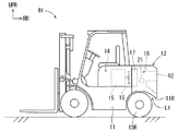
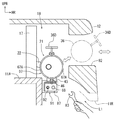
図1に示すように、フォークリフト10の車体11の後方側には、カウンタウエイト12が搭載されている。車体11のエンジンルーム14内には、エンジン15が搭載されている。このエンジン15は、例えば、ディーゼルエンジンにより構成されている。エンジンルーム14の側壁には、不図示の外気取入れ口が設けられている。エンジン15の後側には、エンジン15によって駆動される、つまり、回転されるファン16が設けられている。
As shown in FIG. 1, a
ファン16の後方側には、エンジン15の冷却水を冷却するラジエータ17が設置されている。ファン16は、エンジン15の駆動によって、外気取入れ口から外気(空気)をエンジンルーム14に取り入れてラジエータ17に吹き付ける。これにより、エンジン15の冷却水が冷却される。そして、ラジエータ17を通過した送風は、ラジエータ17の後側に設けられて、前方側が開放された略箱体状に区画された通風室18を経て、カウンタウエイト12の後壁部を前後方向に貫通する後向き吹き出し口19から車両後方へ吹き出される。後向き吹き出し口19は、例えば、車幅方向に長い断面横長矩形状に形成され、カウンタウエイト12の後壁部の上下2個所に平行に貫通している。
A
また、図2に示すように、通風室18には、ラジエータ17の後側に排気ガス浄化装置21が車幅方向に沿って配置され、排気ガスを排出する排気ガス通路の一部をなす排気管22が排気ガス浄化装置21の上流側に接続されている。従って、排気ガス浄化装置21は、排気管22と共に排気ガス通路を構成し、上流側から下流側に排気ガスが通過する間に、排気ガスに含まれる有害物質を除去するものである。
As shown in FIG. 2, an exhaust
ここで、エンジン15は、高効率で耐久性にも優れているが、粒子状物質(PM)、窒素酸化物(NOx)、一酸化炭素(CO)、炭化水素(HC)等の有害物質を、排気ガスと一緒に排出してしまうものである。そこで、排気管22に接続される排気ガス浄化装置21は、後述するように、窒素酸化物(NOx)、一酸化炭素(CO)、炭化水素(HC)等を酸化して除去する酸化触媒(DOC:Diesel Oxidation Catalyst)25(図4、図5参照)を上流側に配置し、粒子状物質(PM)を捕集して除去する粒子状物質除去フィルタ(以下、「DPF」という。)26(図4、図5参照)を下流側に配置して構成されている。
Here, the
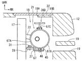
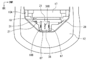
図2及び図3に示すように、排気ガス浄化装置21の下流側の下端部は、車両前後方向に沿って配置された側面視クランク状に折り曲げ形成された取付台座(取付台座部)27に取り付けられている。また、この取付台座27は、通風室18内に車幅方向に沿って配置された平面視細長矩形で平板状の架台28上にボルト31によってボルト止めされている。また、排気ガス浄化装置21の上流側の下端部は、通風室18内の側壁から車幅方向内側に突出する取付用ブラケット29(図4、図5参照)に取り付けられている。
As shown in FIGS. 2 and 3, the lower end on the downstream side of the exhaust
また、図2及び図3に示すように、通風室18の天井部には、上方に開放された車幅方向に長い平面視略矩形状の開口部18Aが形成されている。また、図3に示すように、開口部18Aの車両後方側の側縁部には、車幅方向略中央部から車両後方側へ、平面視コの字状に切り欠かれた切欠き窓部18Bが形成されている。平面視コの字状の切欠き窓部18Bは、排気ガス浄化装置21の軸方向略中央部に配置される浄化用筒体36及び一対のクランプ結合具67の直上に形成されている。また、切欠き窓部18Bは、車両後方側へ、一対のクランプ結合具67間の距離よりも少し広い幅で、浄化用筒体36の車両後方側端縁部に対向する位置まで車両後方側へ平面視コの字状に切り欠かれている。
As shown in FIGS. 2 and 3, a substantially
そして、開口部18A及び切欠き窓部18Bは、車幅方向に長い平面視略矩形状で平板状の蓋部材32が上方からボルト止め等によって固定され、閉塞されている。従って、後述のように、作業者は、蓋部材32を取り外すことによって、切欠き窓部18Bを介して、排気ガス浄化装置21の浄化用筒体36の取り付け、取り外しを行うことができる。
The
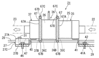
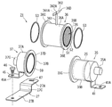
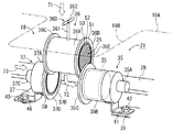
次に、排気ガス浄化装置21の構成について図4乃至図12に基づいて説明する。図4乃至図7に示すように、排気ガス浄化装置21は、上流側に配置される上流筒体35と、下流側に配置される下流筒体37と、上流筒体35と下流筒体37との間に同軸に取り付け、取り外し可能に直列接続される浄化用筒体36と、から構成されている。上流筒体35には、酸化触媒25が収容され、浄化用筒体36には、DPF26が収容されている。
Next, the configuration of the exhaust
図7に示すように、上流筒体35は、排気ガスが流入する流入筒部35Aと、円筒部35Bと、フランジ部35Cと、円筒部35B内に収容される酸化触媒25と、から構成されている。流入筒部35Aは、上流側端部に排気管22(図4、図5参照)が接続される断面円形の筒状に形成されている。円筒部35Bは、円筒状に形成されて、上流側端部が閉塞されて、略中央部に流入筒部35Aとほぼ同径の貫通孔が形成され、この貫通孔の軸方向外側に流入筒部35Aの下流側端部が溶接等によって全周に渡って溶着されている。また、円筒部35Bは、内側に略円柱状に形成された酸化触媒25が下流側に寄せられるように嵌入されている。
As shown in FIG. 7, the
フランジ部35Cは、円筒部35Bの下流側端部に溶接等によって全周に渡って溶着されて鍔状に設けられている(図8参照)。図8に示すように、フランジ部35Cの下流側端面である接続面35Dは、軸方向に直交する環状の平坦面として形成され、浄化用筒体36の上流側フランジ部36Bに当接されて接続される(図4、図5参照)。
The
酸化触媒25は、円筒部35Bの内径寸法にほぼ等しい外径寸法を有するセラミック製のセル状筒体からなり、その軸方向には多数の貫通孔が形成され、内面に白金(Pt)等の貴金属がコーティングされている。そして、酸化触媒25は、所定の温度下で多数の貫通孔に排気ガスを通すことにより、排気ガスに含まれる窒素酸化物(NOx)、一酸化炭素(CO)、炭化水素(HC)等を酸化して除去する。
The
このように構成された上流筒体35は、図5及び図7に示すように、円筒部35Bの下面側に、側面視クランク状に折り曲げて形成された板状の支持部材(第1支持部)41の上端面が、この支持部材41の下端側が流入筒部35Aの下側に位置するように溶接等で固着されている。そして、支持部材41の下端側には、貫通孔41Aが形成されており、この支持部材41が取付用ブラケット29の上面部に載置されて、貫通孔41Aに挿通されたボルト42によりボルト止めされる。このように、上流筒体35は、車体に取り付けられた取付用ブラケット29上に支持部材41を介して固定される。
As shown in FIGS. 5 and 7, a plate-like support member (first support portion) formed by bending in a side view crank shape is formed on the lower surface side of the
次に、図7に示すように、下流筒体37は、浄化用筒体36に収容されたDPF26を通った排気ガスが流入する円筒状の円筒部37Aと、フランジ部37Bと、排気ガスを流出する排出筒部37Cと、から構成されている。円筒部37Aは、上流筒体35の円筒部35Bとほぼ同じ外径で、軸方向の長さが円筒部35Bよりも短い、例えば、約半分の長さの円筒状に形成されている。そして、円筒部37Aは、下流側端部が閉塞されて、略中央部に排出筒部37Cとほぼ同径の貫通孔が形成され、この貫通孔の軸方向外側に排出筒部37Cの上流側端部が溶接等により全周に渡って溶着されている。排出筒部37Cは、下流側端部に排気管23(図4、図5参照)が接続される断面円形の筒状に形成されている。
Next, as shown in FIG. 7, the
フランジ部37Bは、円筒部37Aの上流側端部に溶接等によって全周に渡って溶着されて鍔状に設けられ、上記上流筒体35のフランジ部35Cに対して面対称に形成されている。従って、フランジ部37Bの上流側端面である接続面37Dは、軸方向に直交する環状の平坦面として形成され、浄化用筒体36の下流側フランジ部36Cに当接されて接続される(図4、図5参照)。
The
このように構成された下流筒体37は、図5及び図7に示すように、円筒部37Aの下面側に、側面視クランク状に折り曲げて形成された板状の支持部材(第2支持部)45の上端面が、この支持部材45の下端側が円筒部37Aよりも軸方向下流側に位置するように溶接等で固着されている。そして、支持部材45の下端側には、貫通孔45Aが形成されており、側面視クランク状に折り曲げて形成された板状の取付台座27の下端側27Bの上面部に載置されて、貫通孔45Aに挿通されたボルト46によりボルト止めされる。また、取付台座27は、下流筒体37の軸方向に対して直交する方向に沿って配置され、支持部材45の長手方向に対して直交した状態で、該支持部材45の下端側がボルト止めされている。
As shown in FIGS. 5 and 7, the downstream
支持部材45の下端側にボルト止めされた取付台座27の上端側27Aには、下流筒体37の軸方向に長い長孔47が形成されている。そして、図4乃至図6に示すように、取付台座27は、上端側27Aが架台28の上面部に載置されると共に、上端側27Aの下端側27Bに対向する端縁部から略直角に下方に延出された壁部27Cが、架台28の車両後方側の端部に当接された状態で配置され、長孔47に挿通されたボルト31により架台28にボルト止めされる。
On the
ここで、図5及び図6に示すように、上流筒体35と下流筒体37との間に浄化用筒体36が同軸に取り付けられた場合には、ボルト31は、長孔47の長手方向において下流筒体37に対して反対側の端部の近傍に位置して、ボルト止めされている。また、図9及び図10に示すように、上流筒体35と下流筒体37との間から浄化用筒体36が取り外された場合には、ボルト31は、少し緩められた状態で、長孔47の長手方向において下流筒体37に近い側の端部の近傍に位置している。
Here, as shown in FIGS. 5 and 6, when the
従って、下流筒体37は、支持部材45と架台28上にボルト止めされた取付台座27を介して、長孔47の長さだけ軸方向前後に移動させて固定できる。尚、架台28の車両後方側の端部は、排気ガス浄化装置21の軸方向に沿って、つまり、車幅方向に沿って設けられている。そして、ボルト31を少し緩めて、取付台座27の壁部27Cを架台28の車両後方側の端部に当接させた状態でスライド移動させることによって、下流筒体37を軸方向前後に容易に移動させることができる。
Therefore, the
次に、図7及び図9に示すように、浄化用筒体36は、上流筒体35に収容された酸化触媒25を通った排気ガスが流入する円筒状の円筒部36Aと、上流側フランジ部36Bと、下流側フランジ部36Cと、把持部36Dと、円筒部36A内に収容されるDPF26と、から構成されている。円筒部36Aは、上流筒体35の円筒部35Bとほぼ同じ外径の円筒状に形成され、内側に略円柱状に形成されたDPF26がほぼ全長に渡って嵌入されている。
Next, as shown in FIGS. 7 and 9, the
上流側フランジ部36Bは、円筒部36Aの上流側端部に溶接等によって全周に渡って溶着されて鍔状に設けられている。下流側フランジ部36Cは、円筒部36Aの下流側端部に溶接等によって全周に渡って溶着されて鍔状に設けられている。この上流側フランジ部36Bと下流側フランジ部36Cは、同じ構成である。また、上流側フランジ部36Bの上流側端面である接続面36Eは、軸方向に直交する環状の平坦面として形成され、後述のように、上流筒体35のフランジ部35Cの接続面35Dに当接されて接続される(図8参照)。
The
下流側フランジ部36Cの下流側端面である接続面36F(図9参照)は、軸方向に直交する環状の平坦面として形成され、下流筒体37のフランジ部37Bの接続面37Dに当接されて接続される。また、円筒部36Aの外周面の軸方向中央部には、軸方向視T字形の把持部36Dが外周面から鉛直方向上方に突出して設けられている。把持部36Dは、円筒部36Aの外周面の軸方向中央部から径方向外側に突出する突出軸361と、突出軸361の先端部に形成されたネジ部361Aがねじ込まれるネジ孔362Aが、長手方向中央部に形成された把持軸362と、から構成されている。突出軸361の基端部は、円筒部36Aの外周面にネジ止め、レーザ溶着等によって固定されている。これにより、作業者は、把持部36Dの把持軸362を握って、浄化用筒体36を持ち運ぶことができる。
The
DPF26は、図8に示すように、例えば、セラミックス材料等からなる多孔質な部材によって円柱状に形成されたフィルタ本体26Aと、該フィルタ本体26Aの外周側に全周に渡って設けられた緩衝材となる円筒状の断熱材26Bとから構成されている。フィルタ本体26Aは、軸方向に多数の小孔が設けられたハニカム構造のセル状筒体をなし、各小孔は、隣同士で交互に異なる端部が目封じ部材によって閉塞されている。そして、フィルタ本体26Aは、上流側から各小孔に流入する排気ガスを多孔質材料に通すことで粒子状物質(PM)を捕集し、排気ガスのみを隣の小孔を通じて下流側へと流出させる。
As shown in FIG. 8, the
この場合、フィルタ本体26Aによって捕集された粒子状物質は、定期的に排気ガス温度を上昇させて燃焼除去されるが、その一部は灰となって小孔内に徐々に堆積する。また、その他の未燃焼残留物、例えば、エンジンオイル中の重金属、カルシウム等も徐々に堆積する。そこで、後述のように、浄化用筒体36を取り外し、DPF26をクリーニングする構成となっている(図9参照)。
In this case, the particulate matter collected by the filter
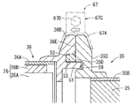
また、図7〜図9に示すように、上流側フランジ部36Bの接続面36Eと、下流側フランジ部36Cの接続面36Fとには、それぞれ、径方向内側周縁部から周方向全周に渡って、ほぼ同じ突出高さで軸方向外側へ突出して、径方向に所定厚さを有する正面視リング状の挿入用リブ部51が、円筒部36Aに対して同軸に設けられている。
As shown in FIGS. 7 to 9, the
また、接続面36Eと接続面36Fとには、それぞれ、挿入用リブ部51の半径方向外側の基端部に沿って周方向全周に渡って軸方向内側に窪む、半径方向断面コの字状に形成されたガスケット挿入溝部52が形成されている。各ガスケット挿入溝部52には、断面略矩形でリング状のガスケット53が、それぞれ1個ずつ挿入用リブ部51に挿通された状態で挿入される(図8参照)。
The
また、図7〜図9に示すように、上流筒体35と下流筒体37との間に浄化用筒体36を同軸に配置した場合に、上流筒体35のフランジ部35Cの接続面35Dと、下流筒体37のフランジ部37Bの接続面37Dとには、それぞれ、各挿入用リブ部51に相対向する位置に、該挿入用リブ部51が挿入される正面視円形状で断面略コの字状の挿入溝部59が周方向全周に渡って形成されている。各挿入溝部59の深さは、各挿入用リブ部51の浄化用筒体36の各フランジ部36B、36Cの各接続面36E、36Fからの突出高さにほぼ等しい深さ寸法に形成されている。各挿入溝部59の径方向の幅は、各挿入用リブ部51の径方向の厚さにほぼ等しい寸法に形成されている。
As shown in FIGS. 7 to 9, when the
尚、各挿入用リブ部51の各接続面36E、36Fからの突出高さは、異なるように形成してもよい。例えば、各挿入用リブ部51の接続面36Eからの突出高さが、一方は、突出高さ約3mmで、他方は、突出高さ約6mmとなるように形成してもよい。そして、各挿入溝部59の深さを、一方は、深さ約3mmで、他方は、深さ約6mmの深さ寸法となるように形成してもよい。これにより、上流筒体35と下流筒体37との間に浄化用筒体36を同軸に配置した場合に、浄化用筒体36の軸方向の向きを常に一定にして、DPF26の排気ガスの流れ方向に合わせて取り付けることができる。
In addition, the projecting height of each
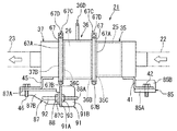
ここで、クランプ結合具67について図2、図4、図5及び図8に基づいて説明する。図2、図4、図5及び図8に示すように、クランプ結合具67は、略U字形又は略V字形(図8には、略U字形の一例を示している。)の断面形状を有する半円弧状の2個の枠体67Aと、各枠体67Aの一端側を回動可能に連結するヒンジ部67Bと、各枠体67Aの他端側を接続するボルト・ナット式の接続部67Cとから構成されている。
Here, the
そして、クランプ結合具67は、接続部67Cのボルト67Dを締め付けることによって、浄化用筒体36の上流側フランジ部36Bと上流筒体35のフランジ部35Cとを軸方向に締め付けるものである。また、クランプ結合具67は、接続部67Cのボルト67Dを締め付けることによって、浄化用筒体36の下流側フランジ部36Cと下流筒体37のフランジ部37Bとを軸方向に締め付けるものである。
The
次に、DPF26のクリーニングを行うために、カウンタウエイト12の上部に設けられた開口部18Aの切欠き窓部18Bを介して、上記のように構成された排気ガス浄化装置21の浄化用筒体36を上流筒体35と下流筒体37との間から取り外す手順について図9及び図10に基づいて説明する。尚、作業者は、先ず、カウンタウエイト12の上部の開口部18Aを覆う蓋部材32(図2参照)を取り外す。そして、作業者は、切欠き窓部18Bを介して、各クランプ結合具67の接続部67Cのボルト67D(図3、図4参照)をナットから外して、各クランプ結合具67を取り外している。続いて、作業者は、開口部18Aの切欠き窓部18Bを介して、以下の作業を行う。
Next, in order to perform cleaning of the
図9及び図10に示すように、作業者は、取付台座27の上端側27Aに形成された長孔47に挿通されるボルト31を少し緩めて、下流筒体37が支持部材45及び取付台座27と一体的に軸方向下流側(図9中、左側)へ移動可能にすると共に、各接続面35D、36Eの間、及び、各接続面36F、37Dの間の軸方向における密着力を解放する。続いて、作業者は、浄化用筒体36の円筒部36Aの外周面から鉛直方向上方に突出する把持部36Dの把持軸362を握った状態で、下流筒体37を浄化用筒体36から離間する方向、つまり、軸方向下流側(図9中、矢印61方向)へ移動させる。
As shown in FIGS. 9 and 10, the operator slightly loosens the
そして、図10に示すように、作業者は、取付台座27を下流筒体37及び支持部材45と一体的に軸方向下流側へ移動させ、取付台座27の上端側に形成される長孔47の長手方向において下流筒体37側の端部をボルト31に当接させ、若しくは、ボルト31の近傍に位置させる。これにより、作業者は、浄化用筒体36の下流側フランジ部36Cの挿入用リブ部51を、下流筒体37のフランジ部37Bの挿入溝部59から抜き出して、下流筒体37を浄化用筒体36から取り外す。
Then, as shown in FIG. 10, the operator moves the mounting
そして、作業者は、把持部36Dの把持軸362を握った状態で、該浄化用筒体36を上流筒体35から離間する方向、つまり、軸方向下流側(図9中、矢印62方向)へ略水平に移動させる。これにより、作業者は、浄化用筒体36の上流側フランジ部36Bの挿入用リブ部51を、上流筒体35のフランジ部35Cの挿入溝部59から抜き出して、浄化用筒体36を上流筒体35から取り外すことができる。
Then, in a state where the operator holds the
その後、作業者は、把持部36Dの把持軸362を握った状態で、該浄化用筒体36を鉛直方向上側(図9中、矢印63方向)へ、つまり、車両上方側へ移動させて、カウンタウエイト12の上部に形成された開口部18Aの切欠き窓部18B(図3参照)から、車両外部に取り出す。これにより、作業者は、上流筒体35を支持部材41及びボルト42を介して取付用ブラケット29上に固定し、且つ、下流筒体37を支持部材45、取付台座27及びボルト31を介して架台28上に軸方向移動可能に取り付けた状態で、把持軸362を持って浄化用筒体36のみを切欠き窓部18B(図3参照)から上方に取り出すことができる。
Thereafter, the operator moves the
そして、浄化用筒体36内に収容されたDPF26のフィルタ本体26A(図8参照)に、例えば、エアガン等を用いて圧縮空気を吹き付け、小孔内に堆積した粒子状物質の灰、未燃焼残留物を除去することにより、DPF26をクリーニングして捕集機能を再生することができる。従って、DPF26をクリーニングした後には、このDPF26を収容した浄化用筒体36を再度、上流筒体35と下流筒体37との間に取り付けることができる(図11参照)。
Then, compressed air is blown to the filter
次に、DPF26をクリーニングした後、上記のように構成された排気ガス浄化装置21の浄化用筒体36を上流筒体35と下流筒体37との間に取り付ける手順について図4、図5、図8、図11及び図12に基づいて説明する。図11に示すように、先ず、作業者は、浄化用筒体36の上流側フランジ部36Bと下流側フランジ部36Cのそれぞれの挿入用リブ部51にリング状のガスケット53を挿通して、該ガスケット53を更に、ガスケット挿入溝部52に挿入する。そして、作業者は、カウンタウエイト12の上部に設けられた開口部18Aの切欠き窓部18B(図3参照)を介して、以下の作業を行う。
Next, after the
先ず、作業者は、浄化用筒体36の円筒部36Aの外周面から鉛直方向上方に突出する把持部36Dの把持軸362を持って、開口部18Aの切欠き窓部18Bから鉛直方向下方(図11中、矢印71方向)へ挿入して、該浄化用筒体36を上流筒体35と下流筒体37との間に位置させる。そして、作業者は、把持部36Dの把持軸362を持った状態で、浄化用筒体36を上流筒体35側(図11中、矢印72方向)へ移動させて、浄化用筒体36の上流側フランジ部36Bの正面視リング状の挿入用リブ部51を、上流筒体35のフランジ部35Cの挿入溝部59に挿入する(図8参照)。尚、上流筒体35は、ボルト42によって支持部材41を介して取付用ブラケット29上に固定されている。
First, the operator holds the
続いて、図11及び図12に示すように、作業者は、取付台座27の上端側27Aに形成された長孔47に挿通されるボルト31が少し緩められているため、把持部36Dの把持軸362を持った状態で、下流筒体37を取付台座27及び支持部材45と一体的に浄化用筒体36側(図11中、矢印73方向)へ移動させる。そして、作業者は、把持部36Dの把持軸362を持った状態で、浄化用筒体36の下流側フランジ部36Cの正面視リング状の挿入用リブ部51(図9参照)を、下流筒体37のフランジ部37Bの挿入溝部59に挿入して、ボルト31を仮締めする。
Subsequently, as shown in FIG. 11 and FIG. 12, the operator holds the
そして、図4、図5及び図8に示すように、作業者は、先ず、浄化用筒体36の上流側フランジ部36Bと上流筒体35のフランジ部35Cの径方向外周部に、環状のクランプ結合具67を組み付ける。そして、作業者は、このクランプ結合具67の接続部67Cのボルト67Dを締め付けて、上流側フランジ部36Bのガスケット挿入溝部52に挿入されたガスケット53を押し潰しつつ、上流側フランジ部36Bの接続面36Eを、相対向する上流筒体35のフランジ部35Cの接続面35Dに当接させて、固定する。
As shown in FIGS. 4, 5 and 8, the operator first places an annular ring on the radially outer periphery of the
続いて、作業者は、浄化用筒体36の下流側フランジ部36Cと下流筒体37のフランジ部37Bの径方向外周部に、環状のクランプ結合具67を組み付ける。その後、作業者は、取付台座27の上端側27Aに形成された長孔47に挿通されるボルト31を少し緩めて、このクランプ結合具67の接合部67Cのボルト67Dを締め付けて、下流側フランジ部36Cのガスケット挿入溝部52に挿入されたガスケット53を押し潰しつつ、下流側フランジ部36Cの接続面36F(図9参照)を、相対向する下流筒体37のフランジ部37Bの接続面37Dに当接させて、固定する。
Subsequently, the operator attaches the
この状態で、作業者は、取付台座27の長孔47に挿通されるボルト31を締め付けて、下流筒体37を支持部材45及び取付台座27を介して架台28上に固定する。図12に示すように、この場合には、ボルト31は、長孔47の長手方向において下流筒体37に対して反対側の端部に当接して、若しくは、この端部の近傍に位置して、締結されている。
In this state, the operator fastens the
これにより、図4及び図5に示すように、排気ガス浄化装置21は、浄化用筒体36が上流筒体35と下流筒体37との間に同軸に配置されると共に、上流筒体35、浄化用筒体36及び下流筒体37の軸方向の位置合わせが行われた状態で、車体11の通風室18内に固定される(図1参照)。その後、作業者は、開口部18A及び切欠き窓部18Bを蓋部材32で覆って、この蓋部材32をボルト止め等によって固定して、DPF26のクリーニングを終了する(図2参照)。
Thereby, as shown in FIGS. 4 and 5, in the exhaust
以上詳細に説明した通り、第1実施形態に係るフォークリフト10では、車体11の後方側には、カウンタウエイト12が搭載されている。また、ラジエータ17とカウンタウエイト12との間に形成された通風室18内に排気ガス浄化装置21が車幅方向に沿って配置されている。通風室18の天井部には、上方に開放された車幅方向に長い平面視略矩形状の開口部18Aが形成されている。また、開口部18Aの車両後方側の側縁部には、車幅方向略中央部から車両後方側へ、平面視コの字状に切り欠かれた切欠き窓部18Bが形成されている。切欠き窓部18Bは、排気ガス浄化装置21の軸方向略中央部に配置される浄化用筒体36及び一対のクランプ結合具67の直上に形成されている。
As described in detail above, in the
また、排気ガス浄化装置21の上流筒体35は、支持部材41を介して取付用ブラケット29にボルト止めされ、固定されている。また、排気ガス浄化装置21の下流筒体37は、支持部材45及び取付台座27を介して、架台28上にボルト31によってボルト止めされている。ボルト31は、取付台座27の上端側27Aに形成された下流筒体37の軸方向に長い長孔47に挿通されて、架台28に締結されている。
The upstream
従って、作業者は、カウンタウエイト12の車両上方側に形成された開口部18Aの切欠き窓部18Bを介して、一対のクランプ結合具67を取り外す。その後、作業者は、車両上方側から取付台座27を取り付けているボルト31を緩めることによって、下流筒体37、支持部材45及び取付台座27を長孔47に沿って軸方向に一体的に移動させることができる。これにより、作業者は、浄化用筒体36の把持部36Dの把持軸362を握った状態で、下流筒体37を迅速に軸方向外側に移動させて、浄化用筒体36だけを取り外すことができる。そして、作業者は、把持部36Dを握った状態で、浄化用筒体36のみを切欠き窓部18Bから車両上方側へ取り出すことができる。
Accordingly, the operator removes the pair of
そして、作業者は、DPF26をクリーニングした後、再び、車両上方側から浄化用筒体36を把持部36Dを把持した状態で、上流筒体35と下流筒体37との間に配置し、下流筒体37を浄化用筒体36側へスライド移動させて、浄化用筒体36を上流筒体35と下流筒体37との間に同軸に直列接続する。続いて、作業者は、車両上方側から開口部18Aの切欠き窓部18Bを介して一対のクランプ結合具67によって各フランジ部35C、36Bと、各フランジ部36C、37Bを挟んで互いに接続する。その後、作業者は、取付台座27をボルト31によって架台28に締結することによって、DPF26のクリーニング作業が終了する。
Then, after cleaning the
これにより、作業者は、クレーン等の設備を用いることなく、客先で排気ガス浄化装置21のクリーニング作業を行うことができるため、排気ガス浄化装置21のクリーニング作業に必要な作業時間の短縮化を図り、フォークリフト10の稼働効率を向上させることができる。また、簡易な構成により、作業者は、開口部18Aの切欠き窓部18Bを介して、車両上方側から浄化用筒体36の取り付け、取り外しをクレーン等を用いないで、容易に行うことができる。
Thereby, the worker can perform the cleaning work of the exhaust
また、浄化用筒体36の上流側と下流側の各フランジ部36B、36Cの各接続面36E、36Fと、上流筒体35と下流筒体37の各フランジ部35C、37Bの各接続面35D、37Dとを当接させた場合には、各フランジ部36B、36Cの各接続面36E、36Fよりも軸方向外側へ、周方向全周に渡って所定高さ突出するリング状の各挿入用リブ部51が、各フランジ部35C、37Bの各接続面35D、37Dの周方向全周に渡って形成された正面視環状の各挿入溝部59に挿入される。これにより、浄化用筒体36が、各挿入用リブ部51を介して、上流筒体35と下流筒体37に対して同軸に支持されるため、上流筒体35と下流筒体37との間に浄化用筒体36を接続するときの作業性の更なる向上を図ることができる。
The connection surfaces 36E and 36F of the
[第2実施形態]
次に、第2実施形態に係るフォークリフト81の概略構成について図13乃至図15に基づいて説明する。尚、図13乃至図15に示される矢印RRは、車両後方側を示し、また、矢印UPRは車両上方側を示している。また、矢印INRは、車幅方向内側を示している。また、以下の説明及び図13乃至図21において上記図1〜図12に示す第1実施形態に係るフォークリフト10、排気ガス浄化装置21の構成等と同一符号は、第1実施形態に係るフォークリフト10、排気ガス浄化装置21の構成等と同一あるいは相当部分を示すものである。
[Second embodiment]
Next, a schematic configuration of a
第2実施形態に係るフォークリフト81の全体構成は、第1実施形態に係るフォークリフト10とほぼ同じ構成である。但し、図13乃至図15に示すように、フォークリフト81のラジエータ17の後方側に設けられた通風室18は、天井部が塞がれて、開口部18A及び切欠き窓部18Bが設けられていない。一方、カウンタウエイト12の後壁部には、上下2箇所に設けられた後向き吹き出し口19に替えて、車幅方向に沿って配置された排気ガス浄化装置21に対向する位置に、後方開口部82が車両前後方向に貫通して設けられている。
The overall configuration of the
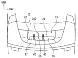
後方開口部82は、図14に示すように、排気ガス浄化装置21の軸方向長さとほぼ等しい車幅方向の長さで、図15に示すように、把持部36Dが設けられた浄化用筒体36が通過し得る車両上下方向の幅を有する断面略横長矩形状に形成されている。後方開口部82は、図14に示すように、車幅方向に沿って配置された排気ガス浄化装置21の約上半分が車両後方側から見えるように設けられている。従って、ラジエータ17を通過した送風は、通風室18を経て、カウンタウエイト12の後壁部を前後方向に貫通する後方開口部82から車両後方へ吹き出される。
The
また、図13及び図15に示すように、車体11の後端部の下端11Rと、後輪13Rとの間には、隙間L1が形成されている。この隙間L1は、例えば、車体11が止まった状態で後輪13Rだけをその場で動かして、後方左側へ曲る方向に最大角度まで据え切りした状態において、作業者が、手に持ったスパナ83等の工具を、排気ガス浄化装置21の下流筒体37を支持する支持部材45及び第2取付台座87の取り付け位置まで挿入してボルト88を操作することが可能となっている。
As shown in FIGS. 13 and 15, a gap L1 is formed between the
また、図15乃至図17に示すように、排気ガス浄化装置21の上流筒体35を支持する側面視クランク状に折り曲げられた支持部材41の下端側は、取付用ブラケット29(図5参照)に替えて、車体フレーム11Aの車両後方側の壁面部から略水平に突出する上流側取付ブラケット85の上面部85Aに載置されて、支持部材41の貫通孔41Aに挿通されたボルト42により上面部85Aにボルト止めされる。上流側取付ブラケット85は、車幅方向から見て側面視L字状に形成され、略矩形の平板状に形成された上面部85Aの車両前方側の端部から鉛直上方に折り曲げられた略矩形の壁部85Bが、車体フレーム11Aの車両後方側の壁面部に溶接等によって固定されている。
As shown in FIGS. 15 to 17, the lower end side of the
また、図15乃至図17に示すように、排気ガス浄化装置21の下流筒体37を支持する側面視クランク状に折り曲げられた支持部材45の下端側は、取付台座27(図5参照)に替えて、下流筒体37の軸方向に沿って水平に配置された第2取付台座(取付台座部)87の上面部87Aに載置されて、支持部材45の貫通孔45Aに挿通されたボルト46により上面部87Aにボルト止めされる。
As shown in FIGS. 15 to 17, the lower end side of the
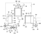
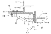
第2取付台座87は、車幅方向外側(図16中、左側)から見て側面視逆L字状に形成され、車幅方向に長い長方形の平板状に形成された上面部87Aと、上面部87Aの車両前方側の端部から鉛直下方に折り曲げられた補強壁部87Bと、補強壁部87Bの車幅方向内側(図16中、右側)の端部から略直角車両後方側に折り曲げられた矩形状の取付案内部87Cと、から構成されている。また、第2取付台座87の取付案内部87Cには、ボルト88が車幅方向外側(図16中、左側)から嵌挿される第1貫通孔89Aと、第1貫通孔89Aの横側に形成されて、後述の細長略円柱状の案内軸92が車幅方向内側(図16中、右側)から嵌挿される第2貫通孔89Bと、が形成されている。
The second mounting
ボルト88は、軸部88Aが浄化用筒体36の各挿入用リブ部51の各フランジ部36B、36Cからの突出高さの合計長さよりも長い長さ(例えば、長さ約40mm〜60mmである。)に形成されると共に、軸部88Aの全長に渡ってネジが形成されている。そして、第2取付台座87の取付案内部87Cは、第2貫通孔89Bに細長略円柱状の案内軸92が嵌挿された状態で、下流側取付ブラケット91の取付部91Aの車幅方向外側面(図16中、左側面)に当接され、若しくは、接近した状態で、第1貫通孔89Aに挿通されたボルト88によってボルト止めされる。
The
下流側取付ブラケット91の取付部91Aは、車体フレーム11Aの車両後方側の壁面部から、下流筒体37の軸方向に対して直交するように突出する略矩形の平板状に形成されている。また、下流側取付ブラケット91は、車両上方から見て側面視L字状に形成され、略矩形の平板状に形成された取付部91Aの車両前方側の端部から略直角車幅方向内側に折り曲げられた略矩形の壁部91Bが、車体フレーム11Aの車両後方側の壁面部に溶接等によって固定されている。
The mounting
また、下流側取付ブラケット91の取付部91Aは、第2取付台座87の取付案内部87Cに形成された第1貫通孔89Aに対向する位置に、不図示の貫通孔が形成され、この貫通孔の車幅方向内側端部に、ナット93が溶接等によって固着されている。また、下流側取付ブラケット91の取付部91Aは、ナット93の横側において、第2取付台座87の取付案内部87Cに形成された第2貫通孔89Bに対向する位置に、不図示の貫通孔が形成され、細長略円柱状の案内軸92が車幅方向内側(図16中、右側)から嵌挿されて、案内軸92の頭部92Aが、取付部91Aに溶接等によって固着されている。
The mounting
案内軸92は、浄化用筒体36の各挿入用リブ部51の各フランジ部36B、36Cからの突出高さの合計長さよりも長い長さ(例えば、長さ約40mm〜60mmである。)の細長略円柱状に形成されている。また、案内軸92の長さは、ボルト88の長さとほぼ同じ長さ、若しくは、ボルト88の長さよりも長い長さに形成されるのが好ましい。また、案内軸92の先端部は、半球状、若しくは、先細り形状に形成されている。
The
ここで、図15及び図16に示すように、上流筒体35と下流筒体37との間に浄化用筒体36が同軸に取り付けられた場合には、下流筒体37は、支持部材45及び第2取付台座87を介して、下流側取付ブラケット91にボルト88によってボルト止めされている。また、案内軸92は、第2取付台座87の取付案内部87Cに形成された第2貫通孔89Bに嵌挿されている。
Here, as shown in FIGS. 15 and 16, when the
また、図18に示すように、各クランプ結合具67を取り外して、上流筒体35と下流筒体37との間から浄化用筒体36が取り外された場合には、ボルト88は所定長さ(例えば、長さ約30mm)だけ緩められた状態で、第2取付台座87は、案内軸92及びボルト88の軸部88Aに案内されて車幅方向外側(図18中、左側)へスライド移動されている。従って、ボルト88を所定長さ(例えば、長さ約30mm)だけ緩めて、第2取付台座87を案内軸92及びボルト88の軸部88Aに沿ってスライド移動させることによって、下流筒体37、支持部材45及び第2取付台座87を一体的に軸方向前後に容易に移動させることができる。
Also, as shown in FIG. 18, when each of the clamp couplings 67 is removed and the
次に、DPF26のクリーニングを行うために、カウンタウエイト12の後壁部に設けられた後方開口部82を介して、上記のように構成された排気ガス浄化装置21の浄化用筒体36を上流筒体35と下流筒体37との間から取り外す手順について図15、図18及び図19に基づいて説明する。
Next, in order to clean the
尚、作業者は、先ず、車体11が止まった状態で後輪13Rだけをその場で動かして、後方左側へ曲る方向に最大角度まで据え切りする。そして、作業者は、図15に示すように、車体11の後端部の下端11Rと、後輪13R(図13参照)との間に形成された隙間L1から、スパナ83等の工具を手で持って差し込み、図19の上側に示すように、ボルト88を所定長さ(例えば、長さ約30mm)だけ緩める。
Note that the worker first moves only the
そして、作業者は、後方開口部82を介して、各クランプ結合具67の接続部67Cのボルト67D(図14、図16参照)をナットから外して、各クランプ結合具67を取り外している。これにより、下流筒体37が支持部材45及び第2取付台座87と一体的に軸方向下流側(図18中、左側)へ移動可能となると共に、各接続面35D、36Eの間、及び、各接続面36F、37Dの間の軸方向における密着力が解放される。続いて、作業者は、後方開口部82を介して、以下の作業を行う。
Then, the worker removes the
図18及び図19に示すように、作業者は、浄化用筒体36の円筒部36Aの外周面から鉛直方向上方に突出する把持部36Dの把持軸362を握った状態で、下流筒体37を浄化用筒体36から離間する方向、つまり、軸方向下流側(図18中、矢印96方向)へ押して、第2取付台座87を下流筒体37及び支持部材45と一体的に案内軸92及びボルト88の軸部88Aに沿って軸方向下流側(図19中、矢印101方向)へスライド移動させる。
As shown in FIGS. 18 and 19, the operator holds the
そして、作業者は、第2取付台座87の取付案内部87Cをボルト88の頭部に当接させ、若しくは、ボルト88の頭部の近傍に位置させる。これにより、作業者は、浄化用筒体36の把持部36Dの把持軸362を握った状態で、浄化用筒体36の下流側フランジ部36Cの挿入用リブ部51を、下流筒体37のフランジ部37Bの挿入溝部59から抜き出して、下流筒体37を浄化用筒体36から取り外す。
Then, the worker brings the mounting
続いて、作業者は、把持部36Dの把持軸362を握った状態で、該浄化用筒体36を上流筒体35から離間する方向、つまり、軸方向下流側(図18中、矢印97方向)へ略水平に移動させる。これにより、作業者は、浄化用筒体36の上流側フランジ部36Bの挿入用リブ部51を、上流筒体35のフランジ部35Cの挿入溝部59から抜き出して、浄化用筒体36を上流筒体35から取り外す。
Subsequently, the operator holds the
その後、作業者は、図15及び図18に示すように、把持部36Dの把持軸362を握った状態で、該把持部36Dを斜め手前側へ傾けた状態で、車両後方側(図18中、矢印98方向)へ移動させて、カウンタウエイト12の後壁部に形成された後方開口部82から、車両外部に取り出す。これにより、作業者は、上流筒体35を支持部材41及びボルト42を介して上流側取付ブラケット85の上面部85A上に固定し、且つ、下流筒体37を支持部材45及び第2取付台座87を介して下流側取付ブラケット91の取付部91Aに軸方向移動可能に取り付けた状態で、把持軸362を持って浄化用筒体36のみを後方開口部82から車両後方へ取り出すことができる。
Thereafter, as shown in FIGS. 15 and 18, the worker grips the
そして、浄化用筒体36内に収容されたDPF26のフィルタ本体26A(図8参照)に、例えば、エアガン等を用いて圧縮空気を吹き付け、小孔内に堆積した粒子状物質の灰、未燃焼残留物を除去することにより、DPF26をクリーニングして捕集機能を再生することができる。従って、DPF26をクリーニングした後には、このDPF26を収容した浄化用筒体36を再度、上流筒体35と下流筒体37との間に取り付けることができる(図20参照)。
Then, compressed air is blown to the filter
次に、DPF26をクリーニングした後、上記のように構成された排気ガス浄化装置21の浄化用筒体36を上流筒体35と下流筒体37との間に取り付ける手順について図15、図16、図20及び図21に基づいて説明する。図20に示すように、先ず、作業者は、浄化用筒体36の上流側フランジ部36Bと下流側フランジ部36Cのそれぞれの挿入用リブ部51にリング状のガスケット53を挿通して、該ガスケット53を更に、ガスケット挿入溝部52に挿入する。そして、作業者は、カウンタウエイト12の後壁部に設けられた後方開口部82(図14参照)を介して、以下の作業を行う。
Next, after cleaning the
先ず、図15及び図20に示すように、浄化用筒体36の円筒部36Aの外周面から鉛直方向上方に突出する把持部36Dの把持軸362を握った状態で、該把持部36Dを斜め手前側へ傾けた状態で、後方開口部82から車両前方側(図20中、矢印105方向)へ挿入して、該浄化用筒体36を上流筒体35と下流筒体37との間に位置させる。そして、作業者は、把持部36Dの把持軸362を持った状態で、浄化用筒体36を上流筒体35側(図20中、矢印106方向)へ移動させて、浄化用筒体36の上流側フランジ部36Bの正面視リング状の挿入用リブ部51を、上流筒体35のフランジ部35Cの挿入溝部59に挿入する(図8参照)。尚、上流筒体35は、ボルト42によって支持部材41を介して上流側取付ブラケット85上に固定されている。
First, as shown in FIGS. 15 and 20, while holding the
続いて、図20及び図21に示すように、作業者は、浄化用筒体36の円筒部36Aの外周面から鉛直方向上方に突出する把持部36Dの把持軸362を握った状態で、下流筒体37を浄化用筒体36側へ、つまり、軸方向上流側(図20中、矢印107方向)へ押して、第2取付台座87を下流筒体37及び支持部材45と一体的に案内軸92及びボルト88の軸部88Aに沿って軸方向上流側(図21中、矢印107方向)へスライド移動させる。そして、作業者は、把持部36Dの把持軸362を持った状態で、浄化用筒体36の下流側フランジ部36Cの正面視リング状の挿入用リブ部51(図18参照)を、下流筒体37のフランジ部37Bの挿入溝部59に挿入する。
Subsequently, as shown in FIGS. 20 and 21, the operator holds the
そして、図16に示すように、作業者は、先ず、浄化用筒体36の上流側フランジ部36Bと上流筒体35のフランジ部35Cの径方向外周部に、環状のクランプ結合具67を組み付ける。そして、作業者は、このクランプ結合具67の接続部67Cのボルト67Dを締め付けて、上流側フランジ部36Bのガスケット挿入溝部52に挿入されたガスケット53を押し潰しつつ、上流側フランジ部36Bの接続面36Eを、相対向する上流筒体35のフランジ部35Cの接続面35Dに当接させて、固定する。
Then, as shown in FIG. 16, first, the operator attaches the
続いて、作業者は、浄化用筒体36の下流側フランジ部36Cと下流筒体37のフランジ部37Bの径方向外周部に、環状のクランプ結合具67を組み付ける。そして、作業者は、このクランプ結合具67の接合部67Cのボルト67Dを締め付けて、下流側フランジ部36Cのガスケット挿入溝部52に挿入されたガスケット53を押し潰しつつ、下流側フランジ部36Cの接続面36F(図9参照)を、相対向する下流筒体37のフランジ部37Bの接続面37Dに当接させて、固定する。
Subsequently, the operator attaches the
この状態で、図15に示すように、作業者は、車体11の後端部の下端11Rと、後輪13R(図13参照)との間に形成された隙間L1から、スパナ等の工具を手で持って差し込み、図21に示すように、ボルト88を締め付けて、下流筒体37を支持部材45及び第2取付台座87を介して下流側取付ブラケット91の取付部91Aに固定する。この場合には、第2取付台座87の取付案内部87Cは、下流側取付ブラケット91の取付部91Aに当接して、若しくは、この取付部91Aの近傍に位置して、固定されている。
In this state, as shown in FIG. 15, the worker removes a tool such as a spanner from the gap L1 formed between the
これにより、DPF26のクリーニング作業が終了し、図16に示すように、排気ガス浄化装置21は、浄化用筒体36が上流筒体35と下流筒体37との間に同軸に配置されると共に、上流筒体35、浄化用筒体36及び下流筒体37の軸方向の位置合わせが行われた状態で、車体11の通風室18内に固定される(図13参照)。
Thus, the cleaning operation of the
以上詳細に説明した通り、第2実施形態に係るフォークリフト81では、車体11の後方側には、カウンタウエイト12が搭載されている。また、ラジエータ17とカウンタウエイト12との間に形成された通風室18内に排気ガス浄化装置21が車幅方向に沿って配置されている。通風室18は、天井部が塞がれている。一方、カウンタウエイト12の後壁部には、車幅方向に沿って配置された排気ガス浄化装置21に対向する位置に、後方開口部82が車両前後方向に貫通して設けられている。
As described in detail above, in the
後方開口部82は、排気ガス浄化装置21の軸方向長さとほぼ等しい車幅方向の長さで、把持部36Dが設けられた浄化用筒体36が通過し得る車両上下方向の幅を有する断面略横長矩形状に形成されている。後方開口部82は、車幅方向に沿って配置された排気ガス浄化装置21の約上半分が車両後方側から見えるように設けられている。
The
また、排気ガス浄化装置21の上流筒体35は、支持部材41を介して上流側取付ブラケット85にボルト止めされ、固定されている。また、排気ガス浄化装置21の下流筒体37は、支持部材45及び第2取付台座87を介して、下流側取付ブラケット91の取付部91Aにボルト88によってボルト止めされている。また、第2取付台座87の取付案内部87Cに形成された第1貫通孔89Aに、ボルト88が車幅方向外側から嵌挿されると共に、取付案内部87Cに形成された第2貫通孔89Bに、下流側取付ブラケット91の取付部91Aから車幅方向外側へ突出する細長略円柱状の案内軸92が嵌挿されている。ボルト88は、案内軸92とほぼ同じ長さで、全長に渡ってネジが形成された軸部88Aを有している。
The upstream
また、車体11の後端部の下端11Rと、後輪13Rとの間には、隙間L1が形成されている。この隙間L1は、車体11が止まった状態で後輪13Rだけをその場で動かして、後輪13Rを据え切りすることによって、作業者が、手に持ったスパナ83等の工具を、排気ガス浄化装置21の下流筒体37を支持する第2取付台座87の取り付け位置まで挿入してボルト88を操作することが可能となっている。
A gap L1 is formed between the
従って、作業者は、後輪13Rを据え切りして、車体11の後端部の下端11Rと、後輪13Rとの間に形成された隙間L1から、スパナ83等の工具を手で持って差し込み、ボルト88を所定長さ(例えば、長さ約30mm)だけ緩める。そして、作業者は、後方開口部82を介して、一対のクランプ結合具67を取り外す。続いて、作業者は、把持部36Dの把持軸362を握った状態で、下流筒体37、支持部材45及び第2取付台座87を一体的に案内軸92及びボルト88の軸部88Aに沿って軸方向下流側へスライド移動させることができる。
Therefore, the worker dismounts the
これにより、作業者は、浄化用筒体36の把持部36Dの把持軸362を握った状態で、下流筒体37を迅速に軸方向外側に移動させて、浄化用筒体36だけを取り外すことができる。そして、作業者は、把持部36Dを把持した状態で、浄化用筒体36のみを後方開口部82から車両後方側へ取り出すことができる。
Accordingly, the operator can quickly move the
そして、作業者は、DPF26をクリーニングした後、再び、浄化用筒体36の上流側フランジ部36Bと下流側フランジ部36Cにガスケット53を取り付ける。その後、作業者は、浄化用筒体36の把持部36Dの把持軸362を把持して、後方開口部82から車両前方側へ挿入して、該浄化用筒体36を上流筒体35と下流筒体37との間に配置する。そして、作業者は、下流筒体37を浄化用筒体36側へスライド移動させて、浄化用筒体36を上流筒体35と下流筒体37との間に同軸に直列接続する。
Then, after cleaning the
続いて、作業者は、車両後方側から後方開口部82を介して一対のクランプ結合具67によって各フランジ部35C、36Bと、各フランジ部36C、37Bを挟んで互いに接続する。その後、作業者は、車体11の後端部の下端11Rと、後輪13Rとの間に形成された隙間L1から、スパナ83等の工具を手で持って差し込み、第2取付台座87をボルト88によって下流側取付ブラケット91に締結することによって、DPF26のクリーニング作業が終了する。
Subsequently, the operator connects the
これにより、作業者は、クレーン等の設備を用いることなく、客先で排気ガス浄化装置21のクリーニング作業を行うことができるため、排気ガス浄化装置21のクリーニング作業に必要な作業時間の短縮化を図り、フォークリフト81の稼働効率を向上させることができる。また、簡易な構成により、作業者は、後方開口部82を介して、車両後方側から浄化用筒体36の取り付け、取り外しをクレーン等を用いないで、容易に行うことができる。
Accordingly, the worker can perform the cleaning operation of the exhaust
本発明の排気ガス浄化装置の取付構造は、前記第1実施形態及び第2実施形態で説明した構成、構造、外観、形状、処理手順等に限定されることはなく、本発明の要旨を変更しない範囲内で種々の変更、改良、追加、削除が可能である。尚、以下の説明において上記図1〜図21に示す前記第1実施形態及び第2実施形態に係る各フォークリフト10、81、及び排気ガス浄化装置21の構成等と同一符号は、前記第1実施形態及び第2実施形態に係る各フォークリフト10、81、及び排気ガス浄化装置21の構成等と同一あるいは相当部分を示すものである。
The mounting structure of the exhaust gas purifying apparatus of the present invention is not limited to the configuration, structure, appearance, shape, processing procedure, and the like described in the first and second embodiments, but changes the gist of the present invention. Various changes, improvements, additions, and deletions can be made without departing from the scope. In the following description, the same reference numerals as those of the
(A)例えば、第2実施形態に係るフォークリフト81では、カウンタウエイト12の後壁部に設けられた後方開口部82の車両後方側端部に、この後方開口部82を覆う横長略矩形状の網状カバーを着脱可能に取り付けてもよい。これにより、通風室18内への異物の進入を抑止することができる。
(A) For example, in the
(B)また、本発明の排気ガス浄化装置の取付構造が各フォークリフト10、81に適用された実施形態を示したが、本発明はその他の産業車両(例えば、ショベルローダ)にも同様に適用可能である。
(B) Although the embodiment in which the mounting structure of the exhaust gas purifying device of the present invention is applied to each of the
11 車体
12 カウンタウエイト
15 エンジン
18A 開口部
18B 切欠き窓部
21 排気ガス浄化装置
22 排気管
26 粒子状物質除去フィルタ(DPF)(浄化処理部材)
27 取付台座(取付台座部)
28 架台
31、88 ボルト
35 上流筒体
35C、37B フランジ部
35D、36E、36F、37D 接続面
36 浄化用筒体
36B 上流側フランジ部
36C 下流側フランジ部
36D 把持部
37 下流筒体
41 支持部材(第1支持部)
45 支持部材(第2支持部)
47 長孔
51 挿入用リブ部
59 挿入溝部
67 クランプ結合具
82 後方開口部
87 第2取付台座(取付台座部)
89B 第2貫通孔
91 下流側取付ブラケット
92 案内軸
DESCRIPTION OF
27 Mounting base (mounting base)
28
45 Supporting member (second supporting portion)
47
89B second through
Claims (5)
前記上流筒体の下流側に設けられた下流筒体と、
前記上流筒体と前記下流筒体との間に同軸に取り付け、取り外し可能に直列接続されて、排気ガスを通して浄化する浄化処理部材を収容する浄化用筒体と、
を有して、車体後部に設けられたカウンタウエイト内に配置された排気ガス浄化装置の取付構造において、
前記上流筒体と前記下流筒体と前記浄化用筒体は、互いに当接して接続される筒体端部に平坦な接続面を有するフランジ部を有し、
断面U字形又はV字形の溝が内側を向いて環状になるように構成されて、前記浄化用筒体の上流側と下流側の各フランジ部と、前記上流筒体と前記下流筒体の各フランジ部とのうちの互いに対向するフランジ部を前記溝内に挟んで、取り付け、取り外し可能に互いに接続する一対のクランプ結合具と、
前記カウンタウエイトの所定位置に貫通して設けられた開口部と、
前記車体に固定されて前記上流筒体を支持する第1支持部と、
前記車体にボルトによるボルト止めにより取り付けられる取付台座部に一端側が固定されて、他端側が前記下流筒体に固定されて該下流筒体を支持する第2支持部と、
を備え、
前記開口部は、該開口部を介して前記一対のクランプ結合具を取り付け、取り外し可能に形成されると共に、前記浄化用筒体が通過し得る大きさに形成され、
前記ボルトを緩めることによって前記取付台座部と前記第2支持部と前記下流筒体とが一体的に前記浄化用筒体の軸方向に沿ってスライド移動可能に構成されている、
排気ガス浄化装置の取付構造。 An upstream cylinder provided in an exhaust gas passage of an engine mounted on a vehicle body;
A downstream cylinder provided on the downstream side of the upstream cylinder,
A purifying cylindrical body that is coaxially mounted between the upstream cylindrical body and the downstream cylindrical body, is detachably connected in series, and houses a purification processing member that purifies through exhaust gas.
In the mounting structure of the exhaust gas purification device disposed in the counter weight provided in the rear of the vehicle body,
The upstream tubular body, the downstream tubular body, and the purifying tubular body have a flange portion having a flat connection surface at a tubular body end portion that is in contact with and connected to each other,
A groove having a U-shaped or V-shaped cross section is formed so as to face inward and form an annular shape. A pair of clamp couplings that sandwich the flanges facing each other out of the flanges in the groove, attach, and detachably connect to each other,
An opening provided through a predetermined position of the counterweight,
A first support portion fixed to the vehicle body and supporting the upstream cylinder;
A second support portion having one end fixed to a mounting pedestal portion attached to the vehicle body with bolts, and the other end fixed to the downstream cylinder to support the downstream cylinder;
With
The opening is attached to the pair of clamp couplers through the opening, is formed to be removable, and is formed in a size through which the purification cylinder can pass,
By loosening the bolt, the mounting pedestal portion, the second support portion, and the downstream cylinder are configured to be integrally slidable along the axial direction of the purification cylinder.
Mounting structure of exhaust gas purifier.
前記開口部は、前記浄化用筒体に対向して前記カウンタウエイトの車両上方側に形成され、
前記取付台座部は、前記カウンタウエイト内に配置された架台に前記開口部を介して車両上方側から前記ボルトによって着脱可能に取り付けられると共に、該ボルトが挿通される前記軸方向に長い長孔が形成されている、
排気ガス浄化装置の取付構造。 The mounting structure of the exhaust gas purifying apparatus according to claim 1,
The opening is formed on the upper side of the vehicle of the counterweight facing the cleaning cylinder,
The mounting pedestal portion is detachably attached to the gantry disposed in the counterweight from the vehicle upper side through the opening from the vehicle upper side, and the axially long slot through which the bolt is inserted is provided. Is formed,
Mounting structure of exhaust gas purifier.
前記開口部は、前記浄化用筒体に対向して前記カウンタウエイトの車両後方側に形成され、
前記取付台座部は、前記第2支持部の下方に配置されて、車体から車両後方側に突出する取付ブラケットに前記ボルトによって着脱可能に取り付けられると共に、前記取付ブラケットから前記軸方向外側へ所定長さ突出する案内軸が嵌挿される貫通孔が形成されている、
排気ガス浄化装置の取付構造。 The mounting structure of the exhaust gas purifying apparatus according to claim 1,
The opening is formed on the vehicle rear side of the counterweight facing the cleaning cylinder,
The mounting pedestal is disposed below the second support, is removably mounted to the mounting bracket projecting rearward from the vehicle body by the bolt, and extends a predetermined length outward from the mounting bracket in the axial direction. A through hole into which a protruding guide shaft is inserted is formed,
Mounting structure of exhaust gas purifier.
前記浄化用筒体は、軸方向略中央部の外周面から車両上方側へ突出して設けられた側面視T字形の把持部を有する、
排気ガス浄化装置の取付構造。 The mounting structure of the exhaust gas purifying apparatus according to any one of claims 1 to 3,
The purifying cylinder has a T-shaped grip in side view provided to protrude upward from the outer peripheral surface of the substantially central portion in the axial direction toward the vehicle upper side.
Mounting structure of exhaust gas purifier.
前記浄化用筒体の上流側と下流側の各フランジ部と、前記上流筒体と前記下流筒体の各フランジ部と、のうちの一方の前記各フランジ部は、前記接続面から周方向全周に渡って、前記接続面よりも軸方向外側へ所定高さ突出するリング状の挿入用リブ部を有し、
前記浄化用筒体の上流側と下流側の各フランジ部と、前記上流筒体と前記下流筒体の各フランジ部と、のうちの他方の前記各フランジ部は、前記挿入用リブ部に相対向する位置に周方向全周に渡って形成されて、前記挿入用リブ部が挿入される正面視環状の挿入溝部を有する、
排気ガス浄化装置の取付構造。 The mounting structure of the exhaust gas purifying apparatus according to any one of claims 1 to 4,
Each of the flange portions on the upstream side and the downstream side of the purifying cylindrical body, and each of the flange portions of the upstream cylindrical body and the downstream cylindrical body, each of the flange portions is entirely circumferential from the connection surface. Over the circumference, has a ring-shaped insertion rib projecting a predetermined height outward in the axial direction from the connection surface,
Each of the flange portions on the upstream side and the downstream side of the purifying tubular body, and each of the flange portions of the upstream tubular body and the downstream tubular body, and each of the other flange portions is relatively opposed to the insertion rib portion. The insertion rib portion is formed over the entire circumference in the circumferential direction, and has an annular insertion groove portion in front view in which the insertion rib portion is inserted.
Mounting structure of exhaust gas purifier.
Priority Applications (3)
| Application Number | Priority Date | Filing Date | Title |
|---|---|---|---|
| JP2018132066A JP7067326B2 (en) | 2018-07-12 | 2018-07-12 | Installation structure of exhaust gas purification device |
| EP19185705.1A EP3594465B1 (en) | 2018-07-12 | 2019-07-11 | Mounting structure of exhaust gas cleaning apparatus |
| CN201910624462.3A CN110714827A (en) | 2018-07-12 | 2019-07-11 | Mounting structure of exhaust gas purifying device |
Applications Claiming Priority (1)
| Application Number | Priority Date | Filing Date | Title |
|---|---|---|---|
| JP2018132066A JP7067326B2 (en) | 2018-07-12 | 2018-07-12 | Installation structure of exhaust gas purification device |
Publications (2)
| Publication Number | Publication Date |
|---|---|
| JP2020008002A true JP2020008002A (en) | 2020-01-16 |
| JP7067326B2 JP7067326B2 (en) | 2022-05-16 |
Family
ID=67253737
Family Applications (1)
| Application Number | Title | Priority Date | Filing Date |
|---|---|---|---|
| JP2018132066A Active JP7067326B2 (en) | 2018-07-12 | 2018-07-12 | Installation structure of exhaust gas purification device |
Country Status (3)
| Country | Link |
|---|---|
| EP (1) | EP3594465B1 (en) |
| JP (1) | JP7067326B2 (en) |
| CN (1) | CN110714827A (en) |
Citations (12)
| Publication number | Priority date | Publication date | Assignee | Title |
|---|---|---|---|---|
| JPH08144753A (en) * | 1994-11-17 | 1996-06-04 | Mazda Motor Corp | Exhaust pipe connection structure |
| JPH11144839A (en) * | 1997-11-05 | 1999-05-28 | Yazaki Corp | Plug cap holder |
| JP2005076459A (en) * | 2003-08-28 | 2005-03-24 | Hino Motors Ltd | Exhaust purification equipment |
| US20070169452A1 (en) * | 2006-01-26 | 2007-07-26 | Grimm David M | Serviceable aligned exhaust aftertreatment assembly |
| WO2010004790A1 (en) * | 2008-07-10 | 2010-01-14 | 日立建機株式会社 | Exhaust gas treatment apparatus |
| JP2010019188A (en) * | 2008-07-11 | 2010-01-28 | Hitachi Constr Mach Co Ltd | Exhaust emission purification device of construction machine |
| JP2010065559A (en) * | 2008-09-09 | 2010-03-25 | Hitachi Constr Mach Co Ltd | Exhaust gas processing device |
| WO2010055717A1 (en) * | 2008-11-11 | 2010-05-20 | 日立建機株式会社 | Exhaust gas processing device |
| JP2012106836A (en) * | 2010-11-17 | 2012-06-07 | Tcm Corp | Diesel particulate filter mounting structure for industrial vehicle |
| JP2014159202A (en) * | 2013-02-19 | 2014-09-04 | Yanmar Co Ltd | Engine device |
| JP2016175588A (en) * | 2015-03-20 | 2016-10-06 | キャタピラー エス エー アール エル | Exhaust system for construction machine |
| JP2017122422A (en) * | 2016-01-08 | 2017-07-13 | コベルコ建機株式会社 | Pump attachment/detachment jig |
Family Cites Families (3)
| Publication number | Priority date | Publication date | Assignee | Title |
|---|---|---|---|---|
| JP2005016374A (en) * | 2003-06-25 | 2005-01-20 | Yanmar Co Ltd | Silencer for diesel engine |
| JP2014122592A (en) * | 2012-12-21 | 2014-07-03 | Hitachi Constr Mach Co Ltd | Purifier of construction machine |
| WO2014168072A1 (en) * | 2013-04-12 | 2014-10-16 | 日立建機株式会社 | Construction machine |
-
2018
- 2018-07-12 JP JP2018132066A patent/JP7067326B2/en active Active
-
2019
- 2019-07-11 EP EP19185705.1A patent/EP3594465B1/en active Active
- 2019-07-11 CN CN201910624462.3A patent/CN110714827A/en active Pending
Patent Citations (12)
| Publication number | Priority date | Publication date | Assignee | Title |
|---|---|---|---|---|
| JPH08144753A (en) * | 1994-11-17 | 1996-06-04 | Mazda Motor Corp | Exhaust pipe connection structure |
| JPH11144839A (en) * | 1997-11-05 | 1999-05-28 | Yazaki Corp | Plug cap holder |
| JP2005076459A (en) * | 2003-08-28 | 2005-03-24 | Hino Motors Ltd | Exhaust purification equipment |
| US20070169452A1 (en) * | 2006-01-26 | 2007-07-26 | Grimm David M | Serviceable aligned exhaust aftertreatment assembly |
| WO2010004790A1 (en) * | 2008-07-10 | 2010-01-14 | 日立建機株式会社 | Exhaust gas treatment apparatus |
| JP2010019188A (en) * | 2008-07-11 | 2010-01-28 | Hitachi Constr Mach Co Ltd | Exhaust emission purification device of construction machine |
| JP2010065559A (en) * | 2008-09-09 | 2010-03-25 | Hitachi Constr Mach Co Ltd | Exhaust gas processing device |
| WO2010055717A1 (en) * | 2008-11-11 | 2010-05-20 | 日立建機株式会社 | Exhaust gas processing device |
| JP2012106836A (en) * | 2010-11-17 | 2012-06-07 | Tcm Corp | Diesel particulate filter mounting structure for industrial vehicle |
| JP2014159202A (en) * | 2013-02-19 | 2014-09-04 | Yanmar Co Ltd | Engine device |
| JP2016175588A (en) * | 2015-03-20 | 2016-10-06 | キャタピラー エス エー アール エル | Exhaust system for construction machine |
| JP2017122422A (en) * | 2016-01-08 | 2017-07-13 | コベルコ建機株式会社 | Pump attachment/detachment jig |
Also Published As
| Publication number | Publication date |
|---|---|
| CN110714827A (en) | 2020-01-21 |
| EP3594465A1 (en) | 2020-01-15 |
| EP3594465B1 (en) | 2021-08-25 |
| JP7067326B2 (en) | 2022-05-16 |
Similar Documents
| Publication | Publication Date | Title |
|---|---|---|
| KR101571192B1 (en) | Exhaust gas processing device | |
| JP5220855B2 (en) | Exhaust gas treatment equipment | |
| CN102057141B (en) | Exhaust gas processing device | |
| KR101539130B1 (en) | Construction machine | |
| CN102046932B (en) | Exhaust gas purification device | |
| CN111512029B (en) | Exhaust gas purification device | |
| JP4927796B2 (en) | Exhaust gas purification device | |
| JP2010043572A (en) | Exhaust emission control device | |
| CN113950572B (en) | Fixed structure of piping | |
| JP7067326B2 (en) | Installation structure of exhaust gas purification device | |
| JP2014221638A (en) | Exhaust emission control system | |
| JP4414453B2 (en) | Hanging point structure of exhaust purification system | |
| JP4933493B2 (en) | Exhaust gas purification device | |
| JP2011196193A (en) | Exhaust emission control device |
Legal Events
| Date | Code | Title | Description |
|---|---|---|---|
| A621 | Written request for application examination |
Free format text: JAPANESE INTERMEDIATE CODE: A621 Effective date: 20201020 |
|
| A977 | Report on retrieval |
Free format text: JAPANESE INTERMEDIATE CODE: A971007 Effective date: 20210909 |
|
| A131 | Notification of reasons for refusal |
Free format text: JAPANESE INTERMEDIATE CODE: A131 Effective date: 20210914 |
|
| A521 | Request for written amendment filed |
Free format text: JAPANESE INTERMEDIATE CODE: A523 Effective date: 20211109 |
|
| TRDD | Decision of grant or rejection written | ||
| A01 | Written decision to grant a patent or to grant a registration (utility model) |
Free format text: JAPANESE INTERMEDIATE CODE: A01 Effective date: 20220329 |
|
| A61 | First payment of annual fees (during grant procedure) |
Free format text: JAPANESE INTERMEDIATE CODE: A61 Effective date: 20220411 |
|
| R151 | Written notification of patent or utility model registration |
Ref document number: 7067326 Country of ref document: JP Free format text: JAPANESE INTERMEDIATE CODE: R151 |