JP2020008244A - Hydrogen combustion equipment - Google Patents
Hydrogen combustion equipment Download PDFInfo
- Publication number
- JP2020008244A JP2020008244A JP2018131543A JP2018131543A JP2020008244A JP 2020008244 A JP2020008244 A JP 2020008244A JP 2018131543 A JP2018131543 A JP 2018131543A JP 2018131543 A JP2018131543 A JP 2018131543A JP 2020008244 A JP2020008244 A JP 2020008244A
- Authority
- JP
- Japan
- Prior art keywords
- hydrogen
- flame
- spray
- coloring
- flange
- Prior art date
- Legal status (The legal status is an assumption and is not a legal conclusion. Google has not performed a legal analysis and makes no representation as to the accuracy of the status listed.)
- Granted
Links
Images




Classifications
-
- F—MECHANICAL ENGINEERING; LIGHTING; HEATING; WEAPONS; BLASTING
- F23—COMBUSTION APPARATUS; COMBUSTION PROCESSES
- F23D—BURNERS
- F23D14/00—Burners for combustion of a gas, e.g. of a gas stored under pressure as a liquid
- F23D14/20—Non-premix gas burners, i.e. in which gaseous fuel is mixed with combustion air on arrival at the combustion zone
- F23D14/22—Non-premix gas burners, i.e. in which gaseous fuel is mixed with combustion air on arrival at the combustion zone with separate air and gas feed ducts, e.g. with ducts running parallel or crossing each other
-
- F—MECHANICAL ENGINEERING; LIGHTING; HEATING; WEAPONS; BLASTING
- F23—COMBUSTION APPARATUS; COMBUSTION PROCESSES
- F23D—BURNERS
- F23D14/00—Burners for combustion of a gas, e.g. of a gas stored under pressure as a liquid
- F23D14/46—Details
- F23D14/48—Nozzles
- F23D14/58—Nozzles characterised by the shape or arrangement of the outlet or outlets from the nozzle, e.g. of annular configuration
-
- F—MECHANICAL ENGINEERING; LIGHTING; HEATING; WEAPONS; BLASTING
- F23—COMBUSTION APPARATUS; COMBUSTION PROCESSES
- F23D—BURNERS
- F23D14/00—Burners for combustion of a gas, e.g. of a gas stored under pressure as a liquid
- F23D14/46—Details
- F23D14/84—Flame spreading or otherwise shaping
Landscapes
- Engineering & Computer Science (AREA)
- Chemical & Material Sciences (AREA)
- Combustion & Propulsion (AREA)
- Mechanical Engineering (AREA)
- General Engineering & Computer Science (AREA)
- Gas Burners (AREA)
- Pre-Mixing And Non-Premixing Gas Burner (AREA)
- Nozzles (AREA)
Abstract
Description
この発明は、透明の水素炎を視認できるように燃焼させる水素燃焼装置に関する。 The present invention relates to a hydrogen combustion device that burns a transparent hydrogen flame so that it can be visually recognized.
水素炎は可視光が少なく、ほぼ透明であるため目視では捉えにくい。このため、目視による水素炎の燃焼状態の確認や検知は困難であるので、水素炎を着色することが提案されていた。 The hydrogen flame has little visible light and is almost transparent, so it is difficult to catch it visually. For this reason, it is difficult to visually confirm and detect the combustion state of the hydrogen flame, and it has been proposed to color the hydrogen flame.
水素炎の着色は、下記特許文献1のように、バーナノズルの先端に炎色反応を呈する塩類を保持して行うものがある。この構成では、バーナから水素炎を発生させると、水素炎がノズル先端の塩類に接して、塩類の炎色反応で水素炎が可視光を放つ。 As described in Patent Document 1 below, coloring of a hydrogen flame is performed by holding a salt exhibiting a flame reaction at the tip of a burner nozzle. In this configuration, when a hydrogen flame is generated from the burner, the hydrogen flame contacts the salt at the tip of the nozzle, and the flame emits visible light due to the flame reaction of the salt.
しかし、炎色反応を呈する塩類が円筒状のノズルの先端に保持された構造であるため、火炎の外炎部のみが着色して見える。また、特許文献1に記載されているように、拡散燃焼するため塩類の塗布量を増大すると火炎の輝度レベルを上昇させることができるが、火炎の輝度レベルの急激な減衰が生じる。この難点を、特許文献1ではノズルの先端に溝を形成して、火炎の立ち上がり部をノズルの内部に引き込むことで解決しているが、それでも、長時間にわたって発色を維持させることは困難である。このため、イベントにおいて演出目的で大きな水素炎を見せることはできなかった。 However, since the salt exhibiting a flame reaction is held at the tip of the cylindrical nozzle, only the outer flame portion of the flame appears to be colored. Further, as described in Patent Literature 1, when the amount of the applied salt is increased due to diffusion combustion, the luminance level of the flame can be increased, but the luminance level of the flame sharply decreases. In Patent Document 1, this difficulty is solved by forming a groove at the tip of the nozzle and drawing the rising portion of the flame into the nozzle, but it is still difficult to maintain color development for a long time. . For this reason, it was not possible to show a large hydrogen flame for the purpose of production at the event.
このため、下記特許文献2のように、炎色反応を呈する発色材を担持した多孔質体からなる発色部材を、水素炎の発せられる方向の先に置いた水素炎着色装置を提案した。この装置は、所望の色を放つ大きな水素炎を長時間にわたって燃焼させることができ、イベント等において使用するのに好適なものである。
Therefore, as in
しかしながら、発色部材を得たうえで、それを運搬したり装置に仕込んだり交換したりする管理作業が必要であって、使用しにくい場合があった。 However, after obtaining the coloring member, a management operation of transporting the charging member, charging the device, or replacing the device is required, and there are cases where it is difficult to use the member.
そこでこの発明は、所望の色を放つ大きな水素炎を長時間にわたって燃焼させることが、手間をかけずにできるようにすることを主な目的とする。 Accordingly, it is a main object of the present invention to enable a large hydrogen flame emitting a desired color to be burned for a long time without any trouble.
そのための手段は、水素を燃焼させて水素炎を発するバーナと、前記水素炎を着色する着色部を備えた水素燃焼装置であって、前記着色部に、前記バーナに隣接する位置に設けられて、炎色反応を呈する着色液を噴霧する噴霧ノズルを備え、前記噴霧ノズルの径方向の周囲に、前記噴霧ノズルが噴霧する際に生じる空気巻き込み流路に位置する巻き込み抑制手段を備えた水素燃焼装置である。 Means for that are a burner that burns hydrogen and emits a hydrogen flame, and a hydrogen combustion device provided with a coloring portion that colors the hydrogen flame, wherein the coloring portion is provided at a position adjacent to the burner. Hydrogen combustion, comprising: a spray nozzle for spraying a colored liquid exhibiting a flame reaction; and a radially-encircling periphery of the spray nozzle, comprising entrainment suppression means positioned in an air entrainment channel generated when the spray nozzle sprays. Device.
この構成では着色部の噴霧ノズルから噴霧された着色液は、周囲の空気を巻き込みながら霧となって適宜の噴霧角で以て飛散する。このときに巻き込み抑制手段が、噴霧に際して生じる空気巻き込み流路に位置して、巻き込む空気の流れを遮断したり減速させたり、空気の量を低減させたりして、空気の巻き込みを抑制する。これにより、噴霧角の狭まりが抑制され、または噴霧角が広げられて広角の噴霧がなされる。噴霧された着色液は、バーナから発せられた水素炎と接触・加熱され炎色反応を呈して水素炎を着色する。 In this configuration, the coloring liquid sprayed from the spray nozzle of the coloring section becomes mist while entraining the surrounding air and scatters at an appropriate spray angle. At this time, the entrainment suppressing means is located in the air entrainment flow path generated at the time of spraying, and cuts off or slows down the flow of the entrained air or reduces the amount of air to suppress the entrainment of air. Thereby, the narrowing of the spray angle is suppressed, or the spray angle is widened to perform wide-angle spraying. The sprayed coloring liquid is brought into contact with and heated by the hydrogen flame emitted from the burner, and exhibits a flame color reaction to color the hydrogen flame.
以上のように、この発明によれば、着色液の広角な噴霧ができるので、着色液と水素炎の接触を広範囲に及ぼすことができる。このため、所望の色を放つ大きな水素炎を得ることが可能である。しかも、水素炎の着色は、着色液の噴霧で行うので、着色した燃焼状態を長時間にわたって継続させることができる。また、多孔質体からなる発色部材を用いる場合とは異なり、着色液を供給できればどこでも使用でき、取扱いが容易である。 As described above, according to the present invention, a wide-angle spray of the coloring liquid can be performed, so that the contact between the coloring liquid and the hydrogen flame can be exerted over a wide range. Therefore, it is possible to obtain a large hydrogen flame which emits a desired color. In addition, since the coloring of the hydrogen flame is performed by spraying the coloring liquid, the colored combustion state can be continued for a long time. In addition, unlike the case of using a coloring member made of a porous material, the coloring material can be used anywhere as long as the coloring liquid can be supplied, and handling is easy.
この発明を実施するための一形態を、以下図面を用いて説明する。 One embodiment for carrying out the present invention will be described below with reference to the drawings.
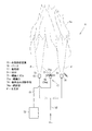
図1に、燃焼状態にある水素燃焼装置11の一部破断正面図を示している。この水素燃焼装置11は、たとえば各種イベントや式典、店舗営業、神社仏閣、庭園などで用いられる聖火や炬火、かがり火などの火炎Faを灯す装置として好適に用いられる。
FIG. 1 shows a partially cutaway front view of the
水素燃焼装置11は、外装体12の内部に備えられている。外装体12は適宜の形状に形成されており、上面が開口した形状である。水素燃焼装置11は、図2にも示したように、外装体12内に形成された平面視円形の隔壁13で囲まれた内側に設けられ、水素を燃焼させて水素炎F(図3参照)を発するバーナ15と、水素炎Fを着色する着色部17を備えている。
The
バーナ15は円筒状であり、平面視円形の炎口51を上に向けている。このようなバーナ15を複数備え、これらバーナ15が、間隔をあけて全体として平面視円形の面を形成するように配設されている。具体的には円を描く円周部15Aと、円周部15Aの内側に位置して十文字を描く内側部15Bを有している。複数のバーナ15によって形成される円形の面の大きさは、外装体12の収容空間12aの上部における隔壁13に収まる大きさである。バーナ15には適宜の径の炎口51を有するものが使用され、バーナ15の数や配置間隔は、全体として所望の大きさの水素炎Fが得られるように適宜設定される。
The
すべてのバーナ15にはガス供給管52から水素が供給される。水素は、バーナ15を出るまで水素100vol%の状態で供給され、バーナ15において拡散燃焼する。
All
またバーナ15には、上端の炎口51の噴射方向に、図4に示したように間隔をあけて邪魔板53を備えるとよい。邪魔板53は水素炎Fの出る方向や態様を、邪魔板53なしの場合と異なるものとする。
Further, the
図4の(a)に示した邪魔板53aは、図5に示したように主に水素炎Fの出る方向に変化を付けるものであって、バーナ15の炎口51に斜めの姿勢で対向する円板で構成されており、支持金具54でバーナ15に保持されている。邪魔板53aの角度や大きさは適宜設定される。
The
図4の(b)に示した邪魔板53bは、主に水素炎Fの出方に変化を付けるものであって、バーナ15の炎口51に真っ直ぐに対峙する板状であり、支持金具54でバーナ15に保持されている。邪魔板53bの大きさや形状は適宜設定される。図4の(b)に示した邪魔板53bは円板形状であり、平面視で炎口51を塞ぐ大きさに形成されている。水素炎Fは、矢印で示したように、支持金具54を有する部位を除く全周から上方へ上がることになる。
The
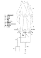
着色部17は、炎色反応を呈する着色液を噴霧する噴霧ノズル71で構成され、バーナ15に隣接する位置に複数設けられる。噴霧ノズル71は円環状に配設された複数の噴霧口71aを有しており、噴霧口71aを上に向けて備えられる。
The
着色部17の配設位置は、バーナ15に囲まれた位置であって、この例では、複数のバーナ15が形成する円周部15Aと内側部15Bの間の4箇所に配設されている。噴霧ノズル71には、図3に概略構造を示したように、着色液を貯蔵するタンク72が、給液路73を介して接続されており、噴霧ノズル71からは適宜の圧搾空気圧力と適宜の液圧力で噴霧がなされるように構成されている。
The arrangement positions of the
給液路73には少なくとも1個のタンク72が備えられる。複数のタンク72を備える場合には、タンク72には、それぞれ異なる色の炎色反応を示す着色液が貯蔵されるとよい。そしてこの場合、給液路73には供給する着色液を切り替える電磁弁等からなる適宜の切り替え手段(図示せず)が備えられる。
The
着色液の例をあげると、黄色に着色するためには炭酸ナトリウムを、青紫色に着色するためは炭酸セシウムを、赤色に着色するには炭酸リチウムを、赤紫色に着色するには炭酸カリウムを、緑色に着色するにはホウ酸アンモニウムを、橙色に着色するには酢酸カルシウムを水溶液にしたものが用いられる。このように着色液に、主に炭酸塩を用い、従来のような塩化物を用いないので、燃焼によって発生する有害な塩素系ガスや微小粒子状物質を抑制できる。 As an example of a coloring liquid, sodium carbonate is used for coloring yellow, cesium carbonate is used for coloring blue-violet, lithium carbonate is used for coloring red, and potassium carbonate is used for coloring red-violet. An aqueous solution of ammonium borate is used for coloring green, and an aqueous solution of calcium acetate is used for coloring orange. As described above, since mainly the carbonate is used for the coloring liquid and the conventional chloride is not used, harmful chlorine-based gas and fine particulate matter generated by combustion can be suppressed.
噴霧ノズル71の径方向の周囲には、噴霧ノズル71が噴霧する際に生じる空気巻き込み流路に位置する巻き込み抑制手段74が設けられている。空気巻き込み流路は、図3に矢印で示したように、主に噴霧ノズル71の外周面に形成され、空気巻き込み流路の空気は噴霧ノズル71の先端の噴霧口71aに向けて流れる。
Around the
巻き込み抑制手段74は、外周方向に張り出す形状の鍔状部74a又は外周を囲む形状の壁状部の少なくとも一方で構成される。図1、図2、図3に示した巻き込み抑制手段74は鍔状部74aである。鍔状部74aは、適宜大で適宜形状の板状であり、空気巻き込み流路において、噴霧ノズル71の外周面に沿って噴霧口71a方向に移動する空気を遮断するとともに、外周方向から流入する巻き込み空気を減少させる。
The
図示例の鍔状部74aは円板形状であり、噴霧ノズル71の先端の噴霧口71aよりも反噴霧方向側であって噴霧口71aに近接した位置に備えられている。
The
このような巻き込み抑制手段74によって、噴霧ノズル71から噴霧される着色液の噴霧角の狭まりが抑制され、または噴霧角が広げられて広角の噴霧がなされる(このような噴霧角の狭まりの抑制と噴霧角の広げを、以下、「噴霧角の広角化」という)。この結果、噴霧ノズル71による噴霧範囲(噴霧径または噴霧幅)が広くなる。
このことを検証するため、次のような複数の試験を行った。
The
In order to verify this, the following multiple tests were performed.
図6に示したように噴霧ノズル71を上方に向けて水を噴霧し、種々の条件で噴霧角θ°を調べた。
Water was sprayed with the
噴霧ノズル71には、加圧式二流体の形式のものを使用した。具体的には、株式会社いけうち製の空円錐ノズルBIMK6004を用い、液(水)圧力を0.1MPa(大気圧基準。以下同じ)とした。
The
この噴霧ノズル71を用いて水を噴霧して、図6に示したように噴霧口71aから100mm先の位置での噴霧径Lmmを測定し、これに基づいて噴霧角θ°を算出する。演算式は次のとおりである。
θ=2・arctan(b/a)
ここで、aは、噴霧口71aから噴霧径Lmmを測定する位置までの距離<100>であり、bは噴霧径Lmmの半分<L/2>である。
Water is sprayed using the
θ = 2 · arctan (b / a)
Here, a is the distance <100> from the
次に試験内容を示す。
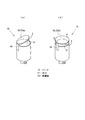
<試験1> 噴霧ノズル71の圧搾空気圧力MPa(0.2、0.3、0.4)と巻き込み抑制手段74、ここでは図7の(a)に示す平面視円形の鍔状部74a(径φ100mm)の有無。
<試験2> 巻き込み抑制手段74、ここでは図7の(a)に示す鍔状部74aの有無と鍔状部74a(径φ100mmとφ120mm)の噴霧ノズル71の噴霧口71aを基準とした高さ。
Next, the test contents are shown.
<Test 1> The compressed air pressure MPa (0.2, 0.3, 0.4) of the
<
ただし、図6に示したように、噴霧口71aを有する部位の全体を露出して噴霧口71aから数mm下を「高」とし、「高」位置よりも4mm低い位置を「中」とし、「中」位置よりも8mm低い位置を「低」とする。高位置、中位置、低位置は、鍔状部74aの上面の位置である。
<試験3> 巻き込み抑制手段74、ここでは鍔状部74aの有無と鍔状部74aの径φmm(20、30、40、50、60、70、90、100、120)。
<試験4> 巻き込み抑制手段74、具体的には図7の(b)に示す鍔状部74aと、鍔状部74a(径φ100mm)における噴霧ノズル71の噴霧方向側の面の外周縁で外周を囲む短円筒形状の壁状部74bを有するものの、壁状部74bの高さhmm(15、20、30)と壁状部74bの有無。
However, as shown in FIG. 6, the entire portion having the
<Test 3>
<
ただし、図7の(b)に示したように、壁状部74bの高さhmmは鍔状部74aの上面からの高さである。
However, as shown in FIG. 7B, the height hmm of the
各試験の結果はつぎのとおりである。 The results of each test are as follows.
<試験1>
圧搾空気圧は、0.2MPa、0.3MPa、0.4MPaの3種類で行った。鍔状部74aからなる巻き込み抑制手段74(径φ100)の噴霧口71aからの高さは「高」位置とした。
<Test 1>
The compressed air pressure was 0.2 MPa, 0.3 MPa, and 0.4 MPa. The height of the entanglement suppressing means 74 (diameter φ100) composed of the
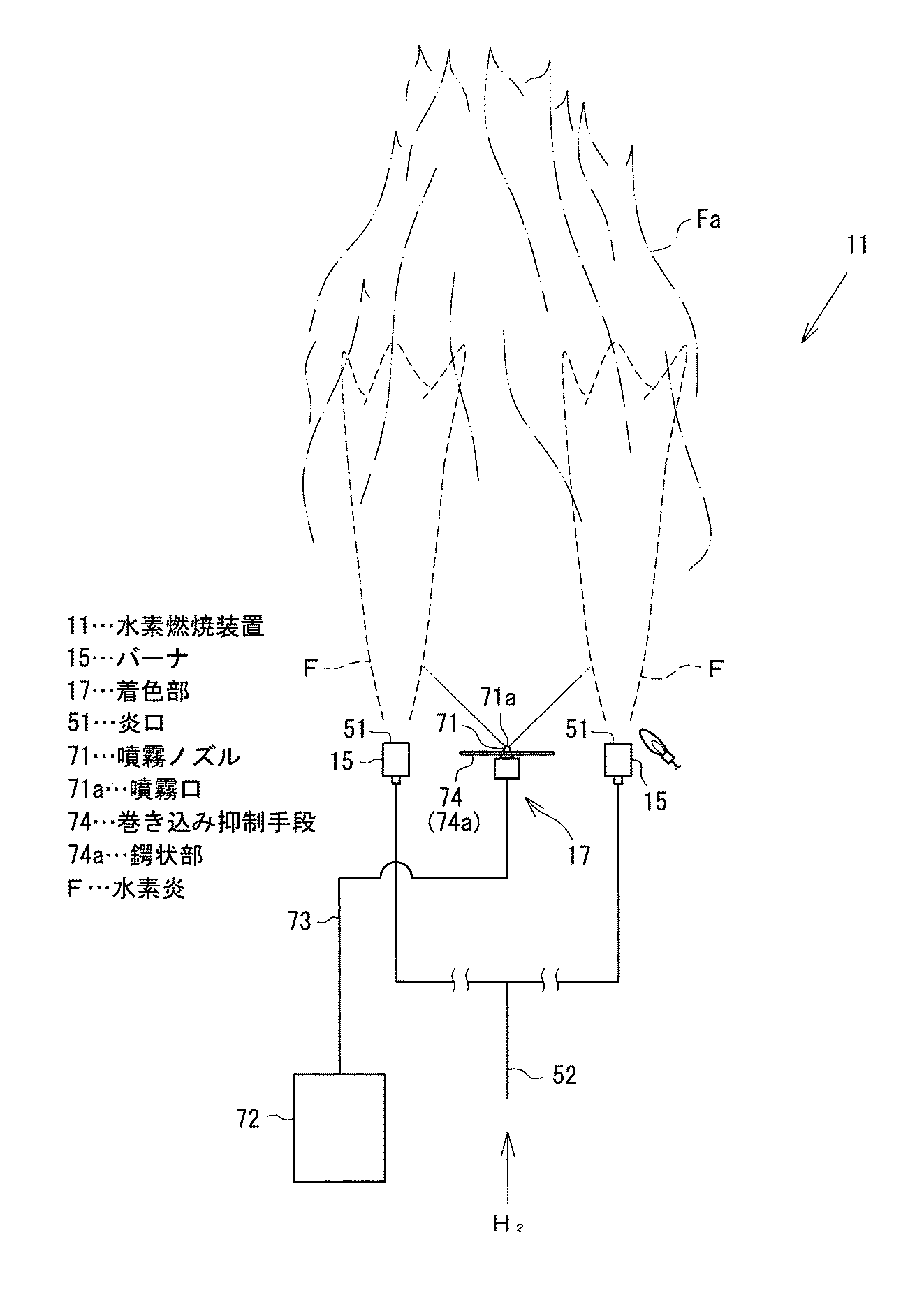
その結果、表1に示したように、鍔状部74aからなる巻き込み抑制手段74なしの場合、圧搾空気圧が0.2MPaの場合には噴霧角は53°であり、0.3MPaの場合も噴霧角は53°である。0.4MPaの場合には噴霧角は狭くなり43°であった。
As a result, as shown in Table 1, without the entrainment suppressing means 74 composed of the
一方、鍔状部74aからなる巻き込み抑制手段74(径φ100)を有する場合は、0.2MPa、0.3MPa、0.4MPaの場合においてそれぞれ、84°、77°、77°であった。
On the other hand, in the case where the entrainment suppressing means 74 (diameter φ100) composed of the
<試験2>
圧搾空気圧は0.3MPaで行った。鍔状部74aからなる巻き込み抑制手段74の噴霧口71aからの高さは「高」位置とした。
<
The compressed air pressure was 0.3 MPa. The height of the
その結果、表2に示したように、鍔状部74aの径φが100mmの場合には、位置が「高」であると噴霧角が77°で、「中」であると61°、「低」であると53°であった。鍔状部74aの径φが120mmの場合には、位置が「高」であると噴霧角が77°、「中」、「低」となるとそれぞれ70°、61°となった。
As a result, as shown in Table 2, when the diameter φ of the
また、試験1における結果と照らし合わせると、圧搾空気圧0.3MPaで鍔状部74aなしの場合に噴霧角が53°であって、表2の径φ100mmの鍔状部74aで取り付け位置「低」の場合の噴霧角と同じであることが判る。このことから、鍔状部74aが径φ100mmで取り付け位置が「低」の場合には噴霧角の広角化にはほとんど寄与しないと判断できる。
In comparison with the results in Test 1, when the compressed air pressure was 0.3 MPa and the
<試験3>
圧搾空気圧は0.3MPaで、鍔状部74aの取り付け位置は「高」で行った。
<Test 3>
The compressed air pressure was 0.3 MPa, and the mounting position of the
その結果、表3に示したように、鍔状部74aなしの場合には噴霧角が53°で、鍔状部74aの径φが20mmの場合には噴霧角が61°となった。以下同様に、径φ30mm、径φ40mm、径φ50mm、径φ60mmの場合に噴霧角は70°であり、径φ70mm、径φ90mm、径φ100mm、径φ120mmの場合に噴霧角は77°であった。
As a result, as shown in Table 3, the spray angle was 53 ° without the
<試験4>
圧搾空気圧は0.3MPaで、鍔状部74aの取り付け位置は「高」で行った。
<
The compressed air pressure was 0.3 MPa, and the mounting position of the
その結果、表4に示したように、壁状部74bなし(h=0mm)の場合は、噴霧角が77°であって、15mmの場合には95°、20mmの場合には100°、30mmの場合にも100°であった。30mmの場合には、噴霧液が壁状部74bに衝突した結果、巻き込み抑制手段74内に液溜まりが見られた。
As a result, as shown in Table 4, when there is no wall-shaped
以上の試験結果から、巻き込み抑制手段74によって、噴霧ノズル71の噴霧角の広角化が図れるといえる。
From the above test results, it can be said that the entrainment suppressing means 74 can increase the spray angle of the
以上のような巻き込み抑制手段74を備えた着色部17では、噴霧角の広角化がはかれるので、噴霧範囲を拡大することができ、水素炎Fの着色が広く確実に行える。このため、火炎Faを大きく見せることができるとともに、炎色濃度を向上させることもでき、図1に示したように、所望の色を放つ大きな火炎Faを得ることが可能である。
In the
しかも、水素炎Fの着色は着色液の噴霧で行うので、着色液の供給が続く限り長時間にわたって着色した燃焼状態を継続させることができる。また、多孔質体からなる発色部材を用いる場合には、固形物であるので運搬や装置に対する仕込みなども必要であるが、本発明では液体の着色液を用いるので、着色液を供給できればどこでも使用でき、取扱いが容易である。
上記試験では、空円錐状で噴霧するノズルを使用したが、扇形状や充円錐状等で噴霧するノズルを使用しても良い。扇形状で噴霧するノズルの場合には、水素燃焼装置11外へ着色液を噴霧することを低減できる。また、着色液を水素炎に対してより絞った形で噴霧できることから、バーナとの位置関係により一対バーナのみ着色することもでき、空円錐状のものと異なる水素炎Fの演出を行うことができる。
In addition, since the coloring of the hydrogen flame F is performed by spraying the coloring liquid, the colored combustion state can be continued for a long time as long as the supply of the coloring liquid is continued. In addition, when a color forming member made of a porous material is used, it is a solid substance, so transportation and preparation into an apparatus are necessary.However, in the present invention, a liquid coloring liquid is used. And easy to handle.
In the above test, a nozzle that sprays in an empty cone shape was used, but a nozzle that sprays in a fan shape or a full cone shape may be used. In the case of a nozzle that sprays in a fan shape, spraying of the coloring liquid outside the
複数種類の着色液を備えた場合には、給液路73の切り替えだけで火炎Faの色の変更も容易である。このため、火炎Faによる演出が効果的に行える。
When a plurality of types of coloring liquids are provided, the color of the flame Fa can be easily changed only by switching the
また、噴霧ノズル71は、複数備えられたバーナ15に囲まれて設けられているうえに、噴霧ノズル71は着色液を広角に噴霧するので、この点からもバーナ15から発せられる水素炎Fを効果的に着色できる。
上記とは反対に、バーナを囲むように噴霧ノズルを配置しても良い。この場合、同種又は異なる種類の着色液を同時或は連続的に変化させることで、より多様な水素炎Fの着色を行うことができる。
Further, the
Contrary to the above, the spray nozzle may be arranged so as to surround the burner. In this case, by changing the same or different kinds of coloring liquids simultaneously or continuously, more various kinds of coloring of the hydrogen flame F can be performed.
水素炎Fを発するバーナ15の炎口51の噴射方向に邪魔板53を備えた場合には、水素炎Fを噴霧ノズル71側に移行させて噴霧された着色液との接触を促したり、発せられる水素炎Fの動きに変化を付けたりして、所望の態様の火炎Faを得ることができる。
In the case where the
以上の構成はこの発明を実施するための一形態であって、この発明は前述の構成のみに限定されるものではなく、その他の構成を採用することもできる。 The above configuration is one mode for carrying out the present invention, and the present invention is not limited to only the above-described configuration, and other configurations can be adopted.
例えば巻き込み抑制手段74は、バーナ15下部からの空気の巻き込みを低減できれば壁状部74bのみで構成することもできる。壁状部74bの形状は、前述の円筒状の他、角筒状、横断面形状が略円錐、台形、丸底などの他の形状にすることもできる。
For example, the
また、巻き込み抑制手段74の鍔状部74aは、前述のような平面視円形のほか、例えば図8に示したような様々な形状にすることができる。図8の(a)は平面視方形の鍔状部74aであり、図8の(b)は、雲形定規のように曲線で囲まれた平面視雲形の鍔状部74aである。外形を様々にするほか、図8の(c)に示したように、適宜位置に細長い三角形状のスリット75を有する鍔状部74aとしてもよい。スリット75を有する部位では、噴霧角の広角化が図れないので、周方向で部分的に噴霧の態様に変化を付けることができる。スリット75の位置を噴霧口71aに対応させると、濃密な噴霧になりやすい部位の希薄化を図ることもできる。
Further, the
バーナ15に備える邪魔板53は、すべてのバーナ15に備えるほか、部分的に備えてもよい。
The
11…水素燃焼装置
15…バーナ
17…着色部
51…炎口
53…邪魔板
71…噴霧ノズル
71a…噴霧口
74…巻き込み抑制手段
74a…鍔状部
74b…壁状部
F…水素炎
DESCRIPTION OF
Claims (6)
前記着色部に、前記バーナに隣接する位置に設けられて、炎色反応を呈する着色液を噴霧する噴霧ノズルを備え、
前記噴霧ノズルの径方向の周囲に、前記噴霧ノズルが噴霧する際に生じる空気巻き込み流路に位置する巻き込み抑制手段を備えた
水素燃焼装置。 A burner that burns hydrogen to emit a hydrogen flame, and a hydrogen combustion device including a coloring unit that colors the hydrogen flame,
The coloring section includes a spray nozzle that is provided at a position adjacent to the burner and sprays a coloring liquid exhibiting a flame reaction.
A hydrogen combustion device comprising: an entrainment suppression unit that is positioned in an air entrainment channel that is generated when the atomization nozzle sprays around a radial direction of the atomization nozzle.
請求項1に記載の水素燃焼装置。 2. The hydrogen combustion apparatus according to claim 1, wherein the entrainment suppressing means is at least one of a flange-shaped portion extending in an outer peripheral direction and a wall-shaped portion surrounding the outer periphery. 3.
前記鍔状部が、前記噴霧ノズルの先端の噴霧口より反噴霧方向側であって前記噴霧口に近接した位置に備えられた
請求項1に記載の水素燃焼装置。 The entanglement suppressing means is a flange-shaped portion that protrudes in the outer peripheral direction,
The hydrogen combustion apparatus according to claim 1, wherein the flange-shaped portion is provided at a position on a side opposite to the spraying direction from a spraying port at a tip end of the spraying nozzle and close to the spraying port.
前記壁状部が前記鍔状部における前記噴霧ノズルの噴霧方向側の面に形成された
請求項1に記載の水素燃焼装置。 As the entanglement suppressing means, a flange-shaped portion extending in the outer peripheral direction and a wall-shaped portion surrounding the outer periphery are provided,
The hydrogen combustion apparatus according to claim 1, wherein the wall-shaped portion is formed on a surface of the flange-shaped portion on a spray direction side of the spray nozzle.
前記噴霧ノズルが前記バーナに囲まれて設けられた
請求項1から請求項4のうちいずれか一項に記載の水素燃焼装置。 A plurality of said burners are provided,
The hydrogen combustion apparatus according to any one of claims 1 to 4, wherein the spray nozzle is provided to be surrounded by the burner.
請求項1から請求項5のうちいずれか一項に記載の水素燃焼装置。
The hydrogen combustion apparatus according to any one of claims 1 to 5, wherein baffles are provided at intervals in an injection direction of a flame port of the burner.
Priority Applications (2)
| Application Number | Priority Date | Filing Date | Title |
|---|---|---|---|
| JP2018131543A JP7357443B2 (en) | 2018-07-11 | 2018-07-11 | Hydrogen combustion equipment |
| PCT/JP2019/019637 WO2020012779A1 (en) | 2018-07-11 | 2019-05-17 | Hydrogen combustion apparatus |
Applications Claiming Priority (1)
| Application Number | Priority Date | Filing Date | Title |
|---|---|---|---|
| JP2018131543A JP7357443B2 (en) | 2018-07-11 | 2018-07-11 | Hydrogen combustion equipment |
Publications (2)
| Publication Number | Publication Date |
|---|---|
| JP2020008244A true JP2020008244A (en) | 2020-01-16 |
| JP7357443B2 JP7357443B2 (en) | 2023-10-06 |
Family
ID=69141366
Family Applications (1)
| Application Number | Title | Priority Date | Filing Date |
|---|---|---|---|
| JP2018131543A Active JP7357443B2 (en) | 2018-07-11 | 2018-07-11 | Hydrogen combustion equipment |
Country Status (2)
| Country | Link |
|---|---|
| JP (1) | JP7357443B2 (en) |
| WO (1) | WO2020012779A1 (en) |
Cited By (1)
| Publication number | Priority date | Publication date | Assignee | Title |
|---|---|---|---|---|
| WO2024090214A1 (en) | 2022-10-26 | 2024-05-02 | 川崎重工業株式会社 | Hydrogen combustion apparatus |
Families Citing this family (1)
| Publication number | Priority date | Publication date | Assignee | Title |
|---|---|---|---|---|
| CN115639247B (en) * | 2022-10-08 | 2026-01-27 | 北京理工大学 | Small-scale visual hydrogen explosion monitoring system and monitoring method |
Citations (4)
| Publication number | Priority date | Publication date | Assignee | Title |
|---|---|---|---|---|
| JPH08161902A (en) * | 1994-12-07 | 1996-06-21 | Doumujiyu:Kk | Portable bonfire device |
| JP2004029051A (en) * | 2002-06-17 | 2004-01-29 | Open Interface Inc | Device and method for presenting space environment and program therefor |
| WO2004094903A1 (en) * | 2003-04-21 | 2004-11-04 | Saintcross Co.,Ltd. | Apparatus for generating color flames |
| JP2016161273A (en) * | 2015-03-05 | 2016-09-05 | 国立大学法人東北大学 | Carbon neutral portable ignition system and ignition system |
Family Cites Families (5)
| Publication number | Priority date | Publication date | Assignee | Title |
|---|---|---|---|---|
| JPH0921509A (en) * | 1995-07-04 | 1997-01-21 | Mitsubishi Heavy Ind Ltd | Hydrogen combustion burner |
| JP2016142467A (en) * | 2015-02-03 | 2016-08-08 | Jxエネルギー株式会社 | Colored flame forming device |
| JP6105131B2 (en) * | 2015-06-30 | 2017-03-29 | 株式会社東芝 | Hydrogen torch |
| JP6670181B2 (en) * | 2016-06-06 | 2020-03-18 | 岩谷産業株式会社 | Hydrogen combustion equipment |
| JP2018014202A (en) * | 2016-07-20 | 2018-01-25 | 株式会社東芝 | Hydrogen torch |
-
2018
- 2018-07-11 JP JP2018131543A patent/JP7357443B2/en active Active
-
2019
- 2019-05-17 WO PCT/JP2019/019637 patent/WO2020012779A1/en not_active Ceased
Patent Citations (4)
| Publication number | Priority date | Publication date | Assignee | Title |
|---|---|---|---|---|
| JPH08161902A (en) * | 1994-12-07 | 1996-06-21 | Doumujiyu:Kk | Portable bonfire device |
| JP2004029051A (en) * | 2002-06-17 | 2004-01-29 | Open Interface Inc | Device and method for presenting space environment and program therefor |
| WO2004094903A1 (en) * | 2003-04-21 | 2004-11-04 | Saintcross Co.,Ltd. | Apparatus for generating color flames |
| JP2016161273A (en) * | 2015-03-05 | 2016-09-05 | 国立大学法人東北大学 | Carbon neutral portable ignition system and ignition system |
Cited By (1)
| Publication number | Priority date | Publication date | Assignee | Title |
|---|---|---|---|---|
| WO2024090214A1 (en) | 2022-10-26 | 2024-05-02 | 川崎重工業株式会社 | Hydrogen combustion apparatus |
Also Published As
| Publication number | Publication date |
|---|---|
| WO2020012779A1 (en) | 2020-01-16 |
| JP7357443B2 (en) | 2023-10-06 |
Similar Documents
| Publication | Publication Date | Title |
|---|---|---|
| JP2020008244A (en) | Hydrogen combustion equipment | |
| GB1599099A (en) | Gas burner assembly | |
| JP7419523B2 (en) | Electronic atomization device and its atomizer | |
| EP3725395A3 (en) | Fluid-gas mixer | |
| CN104154541A (en) | Circular-seam-type injector of gas burner | |
| US20140338651A1 (en) | Burner for a portable stove and portable stove | |
| JP6302886B2 (en) | Function addition equipment for burner equipment | |
| WO2016063339A1 (en) | Firefighting training apparatus | |
| JP2015178911A5 (en) | Burner device for mixed firing, gas nozzle, swirler and boiler | |
| JP2018090275A (en) | Volatilization device | |
| JP5697205B2 (en) | Nozzle device and burner device provided with the nozzle device | |
| CN204042906U (en) | Energy-gathering combustion assembly of a gas burner | |
| US3588304A (en) | Gas and liquid fuel burner | |
| JP2012247135A (en) | Gas turbine combustor | |
| CN210878091U (en) | A laser welding shielding gas nozzle structure and welding device | |
| CN201959444U (en) | Fire extinguishing device with non-toxic agent | |
| CN208295917U (en) | A kind of release formula spray nozzle device for burner | |
| US20160109119A1 (en) | Tubular burner | |
| CN209540887U (en) | Burning torch goes out pneumatic module | |
| JP6347692B2 (en) | Burner device for cremation furnace or incinerator | |
| CN205279091U (en) | Torch burner | |
| JP2015068926A (en) | Fire fighting training device | |
| CN206234821U (en) | Flare Tips and Surface Flare Systems | |
| JP4730924B1 (en) | Nozzle device and burner device provided with the nozzle device | |
| CN110671700A (en) | A shot-suction torch with a porous nozzle |
Legal Events
| Date | Code | Title | Description |
|---|---|---|---|
| A621 | Written request for application examination |
Free format text: JAPANESE INTERMEDIATE CODE: A621 Effective date: 20210623 |
|
| A131 | Notification of reasons for refusal |
Free format text: JAPANESE INTERMEDIATE CODE: A131 Effective date: 20220531 |
|
| A521 | Request for written amendment filed |
Free format text: JAPANESE INTERMEDIATE CODE: A523 Effective date: 20220801 |
|
| A131 | Notification of reasons for refusal |
Free format text: JAPANESE INTERMEDIATE CODE: A131 Effective date: 20221011 |
|
| A521 | Request for written amendment filed |
Free format text: JAPANESE INTERMEDIATE CODE: A523 Effective date: 20221207 |
|
| A02 | Decision of refusal |
Free format text: JAPANESE INTERMEDIATE CODE: A02 Effective date: 20230404 |
|
| A521 | Request for written amendment filed |
Free format text: JAPANESE INTERMEDIATE CODE: A523 Effective date: 20230704 |
|
| A911 | Transfer to examiner for re-examination before appeal (zenchi) |
Free format text: JAPANESE INTERMEDIATE CODE: A911 Effective date: 20230713 |
|
| TRDD | Decision of grant or rejection written | ||
| A01 | Written decision to grant a patent or to grant a registration (utility model) |
Free format text: JAPANESE INTERMEDIATE CODE: A01 Effective date: 20230919 |
|
| A61 | First payment of annual fees (during grant procedure) |
Free format text: JAPANESE INTERMEDIATE CODE: A61 Effective date: 20230926 |
|
| R150 | Certificate of patent or registration of utility model |
Ref document number: 7357443 Country of ref document: JP Free format text: JAPANESE INTERMEDIATE CODE: R150 |