JP2020008246A - Air conditioning system, air conditioning system model selection method, air conditioning system model selection device, and air conditioning system model selection system - Google Patents

Air conditioning system, air conditioning system model selection method, air conditioning system model selection device, and air conditioning system model selection system Download PDF

Info

Publication number
JP2020008246A
JP2020008246A JP2018131709A JP2018131709A JP2020008246A JP 2020008246 A JP2020008246 A JP 2020008246A JP 2018131709 A JP2018131709 A JP 2018131709A JP 2018131709 A JP2018131709 A JP 2018131709A JP 2020008246 A JP2020008246 A JP 2020008246A
Authority
JP
Japan
Prior art keywords
air
living room
air conditioner
room
building
Prior art date
Legal status (The legal status is an assumption and is not a legal conclusion. Google has not performed a legal analysis and makes no representation as to the accuracy of the status listed.)
Pending
Application number
JP2018131709A
Other languages
Japanese (ja)
Inventor
秀和 平井
Hidekazu Hirai
秀和 平井
亀石 圭司
Keiji Kameishi
圭司 亀石
Current Assignee (The listed assignees may be inaccurate. Google has not performed a legal analysis and makes no representation or warranty as to the accuracy of the list.)
Mitsubishi Electric Corp
Original Assignee
Mitsubishi Electric Corp
Priority date (The priority date is an assumption and is not a legal conclusion. Google has not performed a legal analysis and makes no representation as to the accuracy of the date listed.)
Filing date
Publication date
Application filed by Mitsubishi Electric Corp filed Critical Mitsubishi Electric Corp
Priority to JP2018131709A priority Critical patent/JP2020008246A/en
Publication of JP2020008246A publication Critical patent/JP2020008246A/en
Pending legal-status Critical Current

Links

Images

Landscapes

  • Central Air Conditioning (AREA)
  • Air Conditioning Control Device (AREA)

Abstract

【課題】建物内の空間を有効活用しつつ、調和空気の空気循環により建物内を空気調和することが可能な空気調和システムを得ること。【解決手段】空気調和システムは、建物1における第1の居室に設置されて第1の居室の空気調和を行う空気調和機4と、建物内における第2の居室と第1の居室との間で第1の居室内の空気と第2の居室内の空気とを循環させるための循環風路5と、循環風路5を流れる空気流を発生させる循環用送風機6とを備える。空気調和システムは、空気調和機4により空気調和された第1の居室内の空気を循環風路5を通して第2の居室に送り、循環風路5を通して第2の居室内の空気を第1の居室に送る。【選択図】図1An air conditioning system capable of air-conditioning a building by circulating conditioned air while effectively utilizing a space in the building. An air conditioning system is installed in a first living room in a building 1 to perform air conditioning of the first living room, and between the second living room and the first living room in the building. And a circulating air passage 5 for circulating air in the first living room and air in the second living room, and a circulating blower 6 for generating an airflow flowing through the circulating air passage 5. The air conditioning system sends the air in the first living room air-conditioned by the air conditioner 4 to the second living room through the circulating air passage 5 and sends the air in the second living room through the circulating air passage 5 to the first living room. Send to living room. [Selection diagram] Fig. 1

Description

本発明は、建物内を空気調和する空気調和システム、空気調和システムの機種選定方法、空気調和システムの機種選定装置および空気調和システムの機種選定システムに関する。   The present invention relates to an air conditioning system that air-conditions a building, a method of selecting a model of an air conditioning system, a device for selecting a model of an air conditioning system, and a model selection system of an air conditioning system.

近年、戸建て住居では、快適性を向上させるためおよび省エネルギー意識の高まりにより、高気密高断熱住宅が広く普及している。また、ネット・ゼロ・エネルギー・ハウス(Net Zero Energy House:ZEH)への取り組みなど、これまでの省エネルギー基準よりもさらに高いレベルの外皮性能および省エネルギー性を求める動きもある。   2. Description of the Related Art In recent years, highly airtight and highly insulated houses have become widespread in single-family dwellings in order to improve comfort and raise awareness of energy saving. There are also movements to seek higher levels of skin performance and energy savings than previous energy saving standards, such as the approach to the Net Zero Energy House (ZEH).

このように外皮性能が高い高気密高断熱住宅では、建物全体を連続的に空気調和するために必要なエネルギーコストは比較的低くて済む。そこで、居住者の快適性を高めるべく、建物全体を連続的に空気調和するための、種々の空気調和システムが開発されている。   In such a highly airtight and highly insulated house with high outer skin performance, the energy cost required to continuously air-condition the entire building can be relatively low. Accordingly, various air conditioning systems have been developed for continuously conditioning the entire building in order to enhance the comfort of residents.

建物全体を連続的に空気調和する空気調和システムとしては、全館床暖房、ルームエアコンディショナーの全室設置、マルチエアコンディショナーの全室設置、ダクト式セントラル空気調和などがあった。全館床暖房は、放射環境が良く快適性が高い反面、温度応答性が低いという問題があった。ルームエアコンディショナーの全室設置およびマルチエアコンディショナーの全室設置は、部屋毎の室温制御に優れるが、工事費用が嵩む傾向にあった。ダクト式セントラル空気調和は、ダクトにより各部屋に必要な冷温熱を確実に供給できるため、各部屋間の温度ムラを少なくでき、また部屋毎に室温センサおよび可変風量方式(Variable Air Volume:VAV)ユニットを設けることで居住者の好みに応じた部屋毎の温度調整が可能であるなど制御性に優れる。一方で、ダクト式セントラル空気調和は、設備設計に多くのノウハウを必要とするという問題があった。   Air conditioning systems that continuously air-condition the entire building include floor heating throughout the building, installation of all room air conditioners, installation of all multi-air conditioners, and duct-type central air conditioning. Floor heating in the whole building has a good radiation environment and high comfort, but has a problem of low temperature response. The installation of all room air conditioners and the installation of multiple air conditioners are excellent in controlling the room temperature in each room, but the construction cost tends to be high. The duct-type central air conditioning can reliably supply necessary cooling and heating heat to each room by a duct, so that temperature unevenness between the rooms can be reduced, and a room temperature sensor and a variable air volume method (Variable Air Volume: VAV) for each room. By providing the unit, it is possible to control the temperature of each room according to the preference of the occupant, and the controllability is excellent. On the other hand, the duct-type central air conditioning has a problem that much know-how is required for equipment design.

こうした中、高気密高断熱化を活かし、1台程度の家庭用エアコンディショナーを用いて建物全体を空気調和する試みがなされている。すなわち、エアコンディショナーで空気調和された調和空気を、部屋間の空気の密度差または送風機を利用して建物内において循環させ、建物内の全体に調和空気を送るという試みがなされている。家庭用エアコンディショナーには、ルームエアコンディショナーまたは床置形ハウジングエアコンディショナーが使用される。上記のような空気循環による空気調和は、家庭用エアコンディショナーといった汎用品の空気調和機を用いるため、初期費用を抑えられる利点がある。また、上記のような空気調和は、部屋毎に異なる日射または内部発熱に合わせた細かな室温制御、および複数の居住者の冷温感の好みに合わせた室温制御は困難であるものの、建物内の冬期の温度の底上げ、および夏期の室温上昇防止のための空気調和を安価に実現できる点で優れている。   Under these circumstances, an attempt has been made to utilize the high airtightness and high heat insulation to air-condition the entire building using about one household air conditioner. That is, an attempt has been made to circulate conditioned air conditioned by an air conditioner in a building by using a difference in air density between rooms or a blower, and to send conditioned air to the entire building. As a home air conditioner, a room air conditioner or a floor-standing housing air conditioner is used. The air conditioning by air circulation as described above has an advantage that the initial cost can be reduced because a general-purpose air conditioner such as a home air conditioner is used. In addition, in the air conditioning as described above, although it is difficult to control the room temperature in accordance with the solar radiation or internal heat generation that differs for each room and the room temperature in accordance with the cooling sensation of a plurality of residents, it is difficult to control the room temperature. It is excellent in that it can realize low-temperature air conditioning for raising the temperature in winter and preventing a rise in room temperature in summer.

空気循環による空気調和システムとして、特許文献1には、非居室である機械室に設けられた空気調和機によって空気調和された調和空気がダクトにより直接居室に送風され、送風後の空気が機械室に還流される空気調和システムが開示されている。   As an air conditioning system using air circulation, Patent Document 1 discloses that conditioned air that is air-conditioned by an air conditioner provided in a non-living machine room is directly blown into a living room by a duct, and the blown air is blown into the machine room. There is disclosed an air conditioning system that is recirculated to the air conditioning system.

特開2013−133945号公報JP 2013-133945 A

しかしながら、上記特許文献1に開示された空気調和システムは、空間が限られている住居内に機械室を設ける必要があり、居住スペースを減らさなければならないという問題があった。   However, the air-conditioning system disclosed in Patent Literature 1 has a problem in that it is necessary to provide a machine room in a house where space is limited, and the living space must be reduced.

本発明は、上記に鑑みてなされたものであって、建物内の空間を有効活用しつつ、調和空気の空気循環により建物内を空気調和することが可能な空気調和システムを得ることを目的とする。   The present invention has been made in view of the above, and it is an object of the present invention to obtain an air conditioning system capable of air-conditioning a building by air circulation of conditioned air while effectively utilizing a space in the building. I do.

上述した課題を解決し、目的を達成するために、本発明にかかる空気調和システムは、建物における第1の居室に設置されて第1の居室の空気調和を行う空気調和機と、建物内における第2の居室と第1の居室との間で第1の居室内の空気と第2の居室内の空気とを循環させるための循環風路と、循環風路を流れる空気流を発生させる循環用送風機とを備える。空気調和システムは、空気調和機により空気調和された第1の居室内の空気を循環風路を通して第2の居室に送り、循環風路を通して第2の居室内の空気を第1の居室に送る。   In order to solve the above-described problems and achieve the object, an air conditioning system according to the present invention is provided in a first living room of a building to perform air conditioning of the first living room; A circulating air passage for circulating air in the first living room and air in the second living room between the second living room and the first living room, and a circulation for generating an airflow flowing through the circulating air passage Air blower. The air conditioning system sends air in the first living room air-conditioned by the air conditioner to the second living room through the circulation air passage, and sends air in the second living room to the first living room through the circulation air passage. .

本発明によれば、建物内の空間を有効活用しつつ、調和空気の空気循環により建物内を空気調和することが可能な空気調和システムが得られる、という効果を奏する。   ADVANTAGE OF THE INVENTION According to this invention, there exists an effect that the air conditioning system which can air-condition a building by the air circulation of conditioned air while effectively utilizing the space in a building is obtained.

本発明の実施の形態1にかかる空気調和システムを示す概略構成図1 is a schematic configuration diagram illustrating an air conditioning system according to Embodiment 1 of the present invention. 本発明の実施の形態1にかかる空気調和システムの風路の構成を示す模式図FIG. 2 is a schematic diagram illustrating a configuration of an air passage of the air-conditioning system according to Embodiment 1 of the present invention. 本発明の実施の形態1にかかる空気調和システムの空気調和機および循環用送風機の機能の概略構成を示す図The figure which shows schematic structure of the function of the air conditioner of the air conditioner and the air blower for circulation concerning Embodiment 1 of this invention. 本発明の実施の形態1にかかる処理回路のハードウェア構成の一例を示す図FIG. 2 is a diagram illustrating an example of a hardware configuration of a processing circuit according to the first embodiment of the present invention. 本発明の実施の形態1において循環風量と建物内の温熱環境とを試算した試算結果の一例を表す特性図Characteristic diagram showing an example of a trial calculation result of trial calculation of a circulating air volume and a thermal environment in a building in the first embodiment of the present invention. 本発明の実施の形態1において図5に示す特性図とその他の試算結果とを元に作成した、外皮性能ごとの必要循環風量を示す特性図FIG. 5 is a characteristic diagram showing a required circulating air volume for each outer skin performance, which is created based on the characteristic diagram shown in FIG. 本発明の実施の形態1において循環風量と建物内の温熱環境とを図6と異なる条件で試算した外皮性能ごとの必要循環風量を示す特性図FIG. 6 is a characteristic diagram showing the required circulating air volume for each outer skin performance in which the circulating air volume and the thermal environment in the building are trially calculated under conditions different from those in FIG. 本発明の実施の形態1において循環風量と建物内の温熱環境とを図6と異なる条件で試算した外皮性能ごとの必要循環風量を示す特性図FIG. 6 is a characteristic diagram showing the required circulating air volume for each outer skin performance in which the circulating air volume and the thermal environment in the building are trially calculated under conditions different from those in FIG. 本発明の実施の形態1において循環風量と建物内の温熱環境とを試算した試算結果の一例を表す特性図Characteristic diagram showing an example of a trial calculation result of trial calculation of a circulating air volume and a thermal environment in a building in the first embodiment of the present invention. 本発明の実施の形態1において図9に示す外皮平均熱貫流率UA値:0.4W/(m・K)の条件における特性図とその他の外皮平均熱貫流率UA値:0.1W/(m・K)以上0.6W/(m・K)以下の条件における試算結果とを基に作成した、外皮性能ごとの必要循環風量を示す特性図In the first embodiment of the present invention, the characteristic diagram under the condition of outer skin average heat transmission coefficient UA value: 0.4 W / (m 2 · K) shown in FIG. 9 and other outer skin average heat transmission coefficient UA value: 0.1 W / Characteristic diagram showing the required circulating air flow for each skin performance, created based on the results of trial calculations under conditions of (m 2 · K) or more and 0.6 W / (m 2 · K) or less 本発明の実施の形態1において循環風量と建物内の温熱環境とを図10と異なる条件で試算した外皮性能ごとの必要循環風量を示す特性図Characteristic diagram showing the required circulating air volume for each outer skin performance in the first embodiment of the present invention in which the circulating air volume and the thermal environment in the building are estimated under conditions different from those in FIG. 本発明の実施の形態1において循環風量と建物内の温熱環境とを図10と異なる条件で試算した外皮性能ごとの必要循環風量を示す特性図Characteristic diagram showing the required circulating air volume for each outer skin performance in the first embodiment of the present invention in which the circulating air volume and the thermal environment in the building are estimated under conditions different from those in FIG. 本発明の実施の形態1にかかる空気調和システムの機種選定装置の構成を示すブロック図FIG. 1 is a block diagram illustrating a configuration of a model selection device of an air conditioning system according to Embodiment 1 of the present invention. 実施の形態1にかかる機種選定装置のハードウェア構成を示すブロック図FIG. 2 is a block diagram illustrating a hardware configuration of the model selection device according to the first embodiment; 本発明の実施の形態1にかかる機種選定装置での処理によって得られるデータが提示されるまでの手順を表すフローチャート5 is a flowchart illustrating a procedure until data obtained by processing in the model selection device according to the first embodiment of the present invention is presented. 本発明の実施の形態1にかかる空気調和システムの機種選定システムの構成を示すブロック図FIG. 1 is a block diagram showing a configuration of a model selection system of an air conditioning system according to a first embodiment of the present invention. 本発明の実施の形態2にかかる空気調和システムの概略構成図Schematic configuration diagram of an air conditioning system according to Embodiment 2 of the present invention 本発明の実施の形態2にかかる空気調和システムの風路の構成を示す模式図FIG. 4 is a schematic diagram illustrating a configuration of an air path of an air-conditioning system according to Embodiment 2 of the present invention. 本発明の実施の形態3にかかる空気調和システムの概略構成図Schematic configuration diagram of an air conditioning system according to Embodiment 3 of the present invention 本発明の実施の形態3にかかる空気調和システムの風路の構成を示す模式図FIG. 4 is a schematic diagram illustrating a configuration of an air path of an air-conditioning system according to Embodiment 3 of the present invention. 本発明の実施の形態4にかかる空気調和システムの概略構成図Schematic configuration diagram of an air conditioning system according to Embodiment 4 of the present invention. 本発明の実施の形態4にかかる空気調和システムの風路の構成を示す模式図FIG. 9 is a schematic diagram illustrating a configuration of an air path of an air-conditioning system according to Embodiment 4 of the present invention. 本発明の実施の形態5にかかる空気調和システムの風路の構成を示す模式図FIG. 9 is a schematic diagram illustrating a configuration of an air path of an air-conditioning system according to Embodiment 5 of the present invention. 本発明の実施の形態6にかかる空気調和システムの風路の構成を示す模式図FIG. 14 is a schematic diagram illustrating a configuration of an air path of an air-conditioning system according to Embodiment 6 of the present invention. 本発明の実施の形態7にかかる空気調和システムの風路の構成を示す模式図FIG. 14 is a schematic diagram illustrating a configuration of an air path of an air-conditioning system according to Embodiment 7 of the present invention. 本発明の実施の形態8にかかる空気調和システムの風路の構成を示す模式図A schematic diagram showing a configuration of an air path of an air conditioning system according to Embodiment 8 of the present invention. 本発明の実施の形態9にかかる空気調和システムの風路の構成を示す模式図FIG. 14 is a schematic diagram showing a configuration of an air path of an air-conditioning system according to Embodiment 9 of the present invention.

以下に、本発明の実施の形態にかかる空気調和システム、空気調和システムの機種選定方法、空気調和システムの機種選定装置および空気調和システムの機種選定システムを図面に基づいて詳細に説明する。なお、この実施の形態によりこの発明が限定されるものではない。   Hereinafter, an air conditioning system, an air conditioning system model selection method, an air conditioning system model selection device, and an air conditioning system model selection system according to an embodiment of the present invention will be described in detail with reference to the drawings. It should be noted that the present invention is not limited by the embodiment.

実施の形態1.
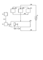
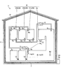
図1は、本発明の実施の形態1にかかる空気調和システムを示す概略構成図である。図2は、本発明の実施の形態1にかかる空気調和システムの風路の構成を示す模式図である。図3は、本発明の実施の形態1にかかる空気調和システムの空気調和機4および循環用送風機6の機能の概略構成を示す図である。図1では、本実施の形態1にかかる空気調和システムが2階建ての戸建住居である建物1に適用された場合について示している。建物1は、外壁11および屋根12により建物内外が仕切られており、内部に居室2、非居室3、空気調和機4、循環風路5、循環用送風機6および断熱部材7を有している。まず、これらの構成要素について説明する。
Embodiment 1 FIG.
FIG. 1 is a schematic configuration diagram illustrating an air-conditioning system according to Embodiment 1 of the present invention. FIG. 2 is a schematic diagram illustrating a configuration of an air passage of the air-conditioning system according to Embodiment 1 of the present invention. FIG. 3 is a diagram illustrating a schematic configuration of functions of the air conditioner 4 and the circulation blower 6 of the air conditioning system according to the first embodiment of the present invention. FIG. 1 illustrates a case where the air-conditioning system according to Embodiment 1 is applied to a building 1 that is a two-story detached house. The inside and outside of the building 1 are partitioned by an outer wall 11 and a roof 12, and have a living room 2, a non-living room 3, an air conditioner 4, a circulating air path 5, a circulating blower 6, and a heat insulating member 7 therein. . First, these components will be described.

居室2は、居住者の基本生活行為において日常生活上の在室時間が長い居室であり、具体的には、リビング、ダイニング、キッチン、寝室および子供部屋等の洋室、和室等である。居室2は、人の在室時間が長いため、人が快適に過ごすための空気調和が行われる、積極的な空気調和対象の部屋である。居室2は、空気調和機が設置された居室2aと空気調和機が取り付けられていない居室2bとからなる。ここで、「空気調和機が取り付けられていない居室」とは、空気調和機を簡単に移動できないようにすることを目的とした工事等による、部屋への空気調和機の固定が行われていない居室である。   The living room 2 is a living room that has a long occupancy time in daily life in the basic living activities of the resident, and specifically includes a living room, a dining room, a kitchen, a western room such as a bedroom and a children's room, and a Japanese room. The living room 2 is a room to be actively air-conditioned, in which air-conditioning is performed for a person to spend comfortably because a person stays for a long time. The living room 2 includes a living room 2a provided with an air conditioner and a living room 2b not provided with an air conditioner. Here, "the living room without an air conditioner attached" means that the air conditioner has not been fixed to the room due to construction or the like aimed at preventing the air conditioner from being easily moved. It is a living room.

空気調和機が設置された居室2aは、空気調和機4が設置されて空気調和機4により空気調和が行われる、建物1における第1の居室である。空気調和機が設置された居室2aには、空気調和機4が設けられている。空気調和機が設置された居室2aは、リビング、ダイニングおよびキッチンが繋げられた一体空間として形成される。また、空気調和機が設置された居室2aは、1階と2階とが上下方向に繋げられた吹き抜けが形成されている。また、空気調和機が設置された居室2aは、1階と2階の間に不図示の階段が形成されている。   The living room 2a where the air conditioner is installed is the first living room in the building 1 where the air conditioner 4 is installed and air conditioning is performed by the air conditioner 4. An air conditioner 4 is provided in the living room 2a where the air conditioner is installed. The living room 2a in which the air conditioner is installed is formed as an integrated space in which a living room, a dining room, and a kitchen are connected. In the living room 2a where the air conditioner is installed, a stairwell is formed in which the first floor and the second floor are vertically connected. In the living room 2a in which the air conditioner is installed, a stair (not shown) is formed between the first floor and the second floor.

空気調和機が設置された居室2aの合計の容積は、空気調和機が取り付けられていない居室2bの合計の容積よりも大きいことが好ましい。具体的には、空気調和機が設置された居室2aの合計の容積をV2aとし、空気調和機が取り付けられていない居室2bの合計の容積をV2bとした場合に、V2aとV2bとは、「V2a>V2b」の関係となるように設定されることが好ましい。なお、空気調和機が設置された居室2aは、必ずしも吹き抜けまたは階段が形成されている必要はない。   It is preferable that the total volume of the living room 2a provided with the air conditioner is larger than the total volume of the living room 2b not provided with the air conditioner. Specifically, when the total volume of the living room 2a in which the air conditioner is installed is V2a and the total volume of the living room 2b in which the air conditioner is not installed is V2b, V2a and V2b are " V2a> V2b ". Note that the living room 2a in which the air conditioner is installed does not necessarily have to have a stairwell or stairs.

空気調和機が取り付けられていない居室2bは、空気調和機が設置された居室2aにおいて空気調和された調和空気が供給されて空気調和が行われる、建物1における第2の居室である。空気調和機が取り付けられていない居室2bは、間仕切壁等により個々に仕切られた個別空間として形成されている。空気調和機が取り付けられていない居室2bとしては、空気調和機が取り付けられていない居室21b、空気調和機が取り付けられていない居室22b、および空気調和機が取り付けられていない居室23bとが2階に設けられている。   The living room 2b to which the air conditioner is not attached is a second living room in the building 1 in which conditioned air that is air-conditioned in the living room 2a where the air conditioner is installed is supplied to perform air conditioning. The living room 2b to which the air conditioner is not attached is formed as an individual space that is individually partitioned by a partition wall or the like. As the living room 2b without an air conditioner, the living room 21b without an air conditioner, the living room 22b without an air conditioner, and the living room 23b without an air conditioner are on the second floor. It is provided in.

非居室3は、居室2以外の空間であり、浴室、トイレ、洗面所、廊下、玄関、クローゼットおよび納戸等である。非居室3には、空気調和機4が設けられていない。非居室3には、がらりまたはドアと床の間の隙間であるアンダーカット等からなる通気用開口10が適宜形成されている。   The non-living room 3 is a space other than the living room 2, and is a bathroom, a toilet, a washroom, a corridor, an entrance, a closet, a closet, and the like. The non-living room 3 is not provided with the air conditioner 4. The non-living room 3 is appropriately formed with a ventilation opening 10 made of garbage or an undercut which is a gap between the door and the floor.

空気調和機4は、空気調和機が設置された居室2aの1階部分に設けられている。空気調和機4は、対象空間に対して空気調和を行う空気調和設備であり、空気を直接的に加熱する蓄熱暖房機もしくはファンヒーター等の暖房機、空気を直接的に加熱または冷却するエアコンディショナーである。本実施の形態1では、空気調和機4は、室内である空気調和機が設置された居室2aの1階部分に設けられた室内機4aと、空気調和機が設置された居室2aの室外である建物1の外部に設けられた室外機4bとを有する空気調和機とする。   The air conditioner 4 is provided on the first floor of the living room 2a where the air conditioner is installed. The air conditioner 4 is an air conditioner that performs air conditioning on a target space, and includes a heating device such as a heat storage heater or a fan heater that directly heats the air, and an air conditioner that directly heats or cools the air. It is. In the first embodiment, the air conditioner 4 includes an indoor unit 4a provided on the first floor of a living room 2a in which the air conditioner is installed, and an outdoor unit 2a in which the air conditioner is installed. The air conditioner includes an outdoor unit 4b provided outside a certain building 1.

本実施の形態1にかかる空気調和機4は、室内機4a、室外機4b、室内機4aと室外機4bとの間で冷媒を循環させるための不図示の冷媒管、および空気調和機4に対する制御指示命令を室内機4aに送信する空気調和機操作端末4cを備える。室外機4bは、不図示の通信線を介して室内機4aと通信可能とされている。   The air conditioner 4 according to the first embodiment includes an indoor unit 4a, an outdoor unit 4b, a refrigerant pipe (not shown) for circulating a refrigerant between the indoor unit 4a and the outdoor unit 4b, and the air conditioner 4. An air conditioner operation terminal 4c for transmitting a control instruction command to the indoor unit 4a is provided. The outdoor unit 4b can communicate with the indoor unit 4a via a communication line (not shown).

空気調和機4は、1つの完結した冷凍サイクルを室内機4aと室外機4bとで形成している。空気調和機4は、冷媒管を通って室内機4aと室外機4bとの間を循環する冷媒を使用して、空調対象空間である室内の空気と室外の空気との間で熱移動を行い、室内に対する空気調和を実現している。すなわち、室内機4aと室外機4bとは冷媒管により接続されており、冷媒管中を流れる冷媒の圧力を室外機4bの備える圧縮機により変化させて冷媒の吸熱および放熱により空気調和を行う。なお、以下では、空気調和機を空調機と表記する場合がある。   The air conditioner 4 forms one complete refrigeration cycle with the indoor unit 4a and the outdoor unit 4b. The air conditioner 4 uses a refrigerant circulating between the indoor unit 4a and the outdoor unit 4b through a refrigerant pipe to perform heat transfer between indoor air, which is a space to be air-conditioned, and outdoor air. , Realizing air conditioning for the room. That is, the indoor unit 4a and the outdoor unit 4b are connected by a refrigerant pipe, and the pressure of the refrigerant flowing in the refrigerant pipe is changed by the compressor provided in the outdoor unit 4b, so that air conditioning is performed by heat absorption and heat radiation of the refrigerant. In the following, an air conditioner may be referred to as an air conditioner.

室内機4aは、室内に配置されて調和空気を室内に送風する。室内機4aは、空気調和機4の動作を制御する空気調和機制御部41と、空気調和機操作端末4c、室外機4bおよび循環用送風機6と通信を行う室内機通信部42とを有する。なお、室内機4aは、その他にも室内機熱交換器および室内機ファンなどの、空気調和機4の動作を実現する一般的な構成部を有する。   The indoor unit 4a is disposed indoors and blows conditioned air into the room. The indoor unit 4a has an air conditioner control unit 41 that controls the operation of the air conditioner 4, and an indoor unit communication unit 42 that communicates with the air conditioner operation terminal 4c, the outdoor unit 4b, and the circulation fan 6. In addition, the indoor unit 4a has other general components that realize the operation of the air conditioner 4, such as an indoor unit heat exchanger and an indoor unit fan.

空気調和機制御部41は、空気調和機4の動作を制御する制御部であり、室内機4aおよび室外機4bの動作を制御することによって空気調和機4の運転を制御する。空気調和機制御部41は、室内機通信部42を介して空気調和機操作端末4cと情報の伝送を行うことができる。空気調和機制御部41は、室内機通信部24を介して空気調和機操作端末4cから受信した指示情報、およびあらかじめ空気調和機制御部41に記憶している情報といった、空気調和機4の運転に関する各種情報に基づいて空気調和機4の動作を制御する。また、空気調和機制御部41は、空気調和機4の本体または空気調和機操作端末4cに設けられた室内温度センサ43により室内の温度を検知し、室内が設定温度となるように空気調和機4の動作を制御する。   The air conditioner control unit 41 is a control unit that controls the operation of the air conditioner 4, and controls the operation of the air conditioner 4 by controlling the operations of the indoor unit 4a and the outdoor unit 4b. The air conditioner control unit 41 can transmit information to and from the air conditioner operation terminal 4c via the indoor unit communication unit 42. The air conditioner control unit 41 operates the air conditioner 4 such as instruction information received from the air conditioner operation terminal 4c via the indoor unit communication unit 24 and information stored in the air conditioner control unit 41 in advance. The operation of the air conditioner 4 is controlled based on various information related to the air conditioner 4. Further, the air conditioner control unit 41 detects the temperature of the room with the indoor temperature sensor 43 provided in the main body of the air conditioner 4 or the air conditioner operation terminal 4c, and adjusts the temperature of the air conditioner so that the room is at the set temperature. 4 is controlled.

また、空気調和機制御部41は、例えば、図4に示したハードウェア構成の処理回路として実現される。図4は、本発明の実施の形態1にかかる処理回路のハードウェア構成の一例を示す図である。空気調和機制御部41が図4に示す処理回路により実現される場合、空気調和機制御部41は、例えば、図4に示すメモリ102に記憶されたプログラムをプロセッサ101が実行することにより、実現される。また、複数のプロセッサおよび複数のメモリが連携して上記機能を実現してもよい。また、空気調和機制御部41の機能のうちの一部を電子回路として実装し、他の部分をプロセッサ101およびメモリ102を用いて実現するようにしてもよい。   The air conditioner control unit 41 is realized as, for example, a processing circuit having a hardware configuration illustrated in FIG. FIG. 4 is a diagram illustrating an example of a hardware configuration of the processing circuit according to the first embodiment of the present invention. When the air conditioner control unit 41 is realized by the processing circuit illustrated in FIG. 4, the air conditioner control unit 41 is realized by, for example, the processor 101 executing a program stored in the memory 102 illustrated in FIG. Is done. Further, a plurality of processors and a plurality of memories may cooperate to realize the above function. Further, a part of the functions of the air conditioner control unit 41 may be implemented as an electronic circuit, and the other part may be realized using the processor 101 and the memory 102.

また、室内機通信部42を、同様にメモリ102に記憶されたプログラムをプロセッサ101が実行することにより、実現されるように構成してもよい。また、室内機通信部42を実現するためのプロセッサおよびメモリは、空気調和機制御部41を実現するプロセッサおよびメモリと同一であってもよいし、別のプロセッサおよびメモリであってもよい。   Further, the indoor unit communication unit 42 may be configured to be realized by the processor 101 executing a program similarly stored in the memory 102. Further, the processor and the memory for realizing the indoor unit communication unit 42 may be the same as the processor and the memory for realizing the air conditioner control unit 41, or may be another processor and memory.

空気調和機4の空気調和容量は、建物1における冷房および暖房のそれぞれの最大負荷以上とする。最大負荷は、気象条件、建物外皮、内部発熱等を考慮した負荷計算により算出する。余りに過大な容量の空気調和機の選定は経済性を損なうので、最大負荷に裕度を乗じた程度の空気調和容量とすることが好ましい。   The air conditioning capacity of the air conditioner 4 is equal to or more than the maximum load of each of the cooling and heating in the building 1. The maximum load is calculated by a load calculation in consideration of weather conditions, building skin, internal heat generation, and the like. Since the selection of an air conditioner having an excessively large capacity impairs economic efficiency, it is preferable that the air conditioner has a maximum load multiplied by a margin.

循環風路5は、給気風路5aと環気風路5bからなる。給気風路5aは、一端側が空気調和機が設置された居室2aに接続されるとともに他端側が空気調和機が取り付けられていない居室2bに接続されて、空気調和機が設置された居室2aの空気を空気調和機が取り付けられていない居室2bに導くための風路である。環気風路5bは、一端側が空気調和機が設置された居室2aに接続されるとともに他端側が空気調和機が取り付けられていない居室2bに接続されて、空気調和機が取り付けられていない居室2bの空気を空気調和機が設置された居室2aに導くための風路である。   The circulation air passage 5 includes a supply air passage 5a and a ring air passage 5b. The supply air passage 5a has one end connected to the living room 2a in which the air conditioner is installed, and the other end connected to the living room 2b in which the air conditioner is not installed. This is an air passage for guiding air to the living room 2b to which no air conditioner is attached. The airflow path 5b has one end connected to the living room 2a in which the air conditioner is installed, and the other end connected to the living room 2b in which the air conditioner is not installed, and the living room 2b in which the air conditioner is not installed. Is an air passage for guiding the air of the air to the living room 2a where the air conditioner is installed.

本実施の形態1においては、循環風路5は、1部屋の空気調和機が設置された居室2aと、3部屋の空気調和機が取り付けられていない居室2bとの、合計4部屋に接続されている。すなわち、給気風路5aの一端側は、空気調和機が設置された居室2aに接続されている。給気風路5aの他端側は、3つに分岐して、空気調和機が取り付けられていない居室21b、空気調和機が取り付けられていない居室22bおよび空気調和機が取り付けられていない居室23bに接続されている。環気風路5bの一端側は、空気調和機が設置された居室2aに接続されている。環気風路5bの他端側は、3つに分岐して、空気調和機が取り付けられていない居室21b、空気調和機が取り付けられていない居室22bおよび空気調和機が取り付けられていない居室23bに接続されている。   In the first embodiment, the circulation air passage 5 is connected to a total of four rooms, that is, one room 2a in which an air conditioner is installed and three rooms 2b in which no air conditioner is installed. ing. That is, one end side of the supply air passage 5a is connected to the living room 2a in which the air conditioner is installed. The other end side of the supply air passage 5a is branched into three into a living room 21b without an air conditioner, a living room 22b without an air conditioner, and a living room 23b without an air conditioner. It is connected. One end of the airflow path 5b is connected to the living room 2a in which the air conditioner is installed. The other end side of the airflow path 5b is branched into three, into a living room 21b without an air conditioner, a living room 22b without an air conditioner, and a living room 23b without an air conditioner. It is connected.

循環風路5にはダクトが採用されている。なお、循環風路5は、風が循環して流れる一連の風路として形成されていればよく、ダクトを設けずに、部屋間を繋いでいるスペースまたはその他のスペースを利用して、各居室2に開口を設けてもよい。部屋間を繋いでいるスペースの例は、たとえば廊下または階段などである。その他のスペースの例は、たとえば床下、階間および天井裏などである。居室2に設けられる開口の例は、たとえば、がらり、アンダーカットなどである。また、循環風路5中にダンパーなど風量を調整する機構を設け、循環風路5内を流れる空気の風量である循環風量を調整できる構成とされてもよい。   A duct is employed for the circulation air passage 5. Note that the circulation air passage 5 may be formed as a series of air passages through which the wind circulates, and without using a duct, a space connecting the rooms or another space may be used. 2 may be provided with an opening. Examples of spaces connecting the rooms are, for example, corridors or stairs. Examples of other spaces are, for example, below the floor, between floors and above the ceiling. Examples of the opening provided in the living room 2 include, for example, garaku and undercut. In addition, a mechanism that adjusts the air volume such as a damper may be provided in the circulation air passage 5 to adjust the circulation air volume, which is the air volume of the air flowing in the circulation air passage 5.

給気風路5aの一端には、吸込口8aが設けられている。吸込口8aは、空気調和機が設置された居室2aの天井面に接している。なお、吸込口8aは、空気調和機が設置された居室2aにおける天井面以外の面に接していてもよい。また、給気風路5aの他端側の3つの分岐端には、吹出口9aが設けられている。すなわち、給気風路5aは吹出口9aの数に合わせて風路が分岐している。吹出口9aは、空気調和機が取り付けられていない居室2bの床面に接している。なお、吹出口9aは、空気調和機が取り付けられていない居室2bにおける床面以外に接していてもよい。したがって、給気風路5aは、空気調和機が設置された居室2aを起点とし、空気調和機が取り付けられていない居室2bを終点とした風路であり、空気調和機が設置された居室2aの空気を、空気調和機が取り付けられていない居室2bに分配する風路である。また、給気風路5aの途中には循環用送風機6が設けられている。   An inlet 8a is provided at one end of the supply air passage 5a. The suction port 8a is in contact with the ceiling surface of the living room 2a where the air conditioner is installed. Note that the suction port 8a may be in contact with a surface other than the ceiling surface in the living room 2a where the air conditioner is installed. Further, at three branch ends on the other end side of the supply air passage 5a, an outlet 9a is provided. In other words, the supply air passage 5a is branched according to the number of the outlets 9a. The outlet 9a is in contact with the floor of the living room 2b to which the air conditioner is not attached. Note that the outlet 9a may be in contact with a part other than the floor of the living room 2b to which the air conditioner is not attached. Therefore, the supply air passage 5a is an air passage that starts from the living room 2a in which the air conditioner is installed and ends in the living room 2b in which the air conditioner is not installed. This is an air passage that distributes air to the living room 2b to which no air conditioner is attached. Further, a circulation blower 6 is provided in the middle of the supply air passage 5a.

環気風路5bの一端には、吹出口である吹出口9bが設けられている。吹出口9bは、空気調和機が設置された居室2aの天井面に接している。なお、吹出口9bは、空気調和機が設置された居室2aの天井面以外の面に接していてもよい。また、環気風路5bの他端側の3つの分岐端には、吸込口である吸込口8bが設けられている。吸込口8bは、空気調和機が取り付けられていない居室2bの天井面に接している。なお、吸込口8bは、空気調和機が取り付けられていない居室2bにおける天井面以外に接していてもよい。環気風路5bは、吸込口8bの数の風路が合流している。したがって環気風路5bは、空気調和機が取り付けられていない居室2bを起点とし、空気調和機が設置された居室2aを終点とした風路であり、空気調和機が取り付けられていない居室2bの空気を風路内で混合し、空気調和機が設置された居室2aに戻す風路である。   An outlet 9b, which is an outlet, is provided at one end of the airflow path 5b. The outlet 9b is in contact with the ceiling surface of the living room 2a where the air conditioner is installed. Note that the outlet 9b may be in contact with a surface other than the ceiling surface of the living room 2a in which the air conditioner is installed. In addition, a suction port 8b, which is a suction port, is provided at three branch ends on the other end side of the airflow path 5b. The suction port 8b is in contact with the ceiling surface of the living room 2b to which the air conditioner is not attached. In addition, the suction port 8b may be in contact with a part other than the ceiling surface of the living room 2b to which the air conditioner is not attached. The air passages 5b have the same number of air passages as the number of the suction ports 8b. Therefore, the ring air passage 5b is an air passage that starts from the living room 2b where the air conditioner is not installed and ends with the living room 2a where the air conditioner is installed. This is an air path in which air is mixed in the air path and returned to the living room 2a where the air conditioner is installed.

循環用送風機6は、給気風路5aの風路中に設けられて、空気調和機が設置された居室2aを起点とし、空気調和機が取り付けられていない居室2bを介して空気調和機が設置された居室2aに戻る空気流を発生させる送風機である。循環用送風機6は、循環風路5内を流れる空気流を発生させる送風部31と、後述する端末制御部63の制御に基づいて送風部31の駆動を制御する送風機制御部32と、送風機操作端末50と無線通信または有線通信により通信を行う送風機通信部33とを有し、外部電源から供給される電力により駆動する。循環用送風機6は、風量を調整できるように、風量が無段階で可変とされ、または風量が複数段階に可変とされている。送風機制御部32は、後述する送風機操作端末60の端末制御部63からの制御に従って風量を調整して送風部31の駆動を制御する。なお、循環用送風機6は、環気風路5bに設けられてもよい。   The circulation blower 6 is provided in the air passage of the supply air passage 5a, starts from the living room 2a where the air conditioner is installed, and installs the air conditioner through the living room 2b where the air conditioner is not installed. This is a blower that generates an airflow returning to the closed living room 2a. The circulating blower 6 includes a blower 31 that generates an airflow flowing in the circulating air passage 5, a blower controller 32 that controls driving of the blower 31 based on the control of a terminal controller 63 described below, and a blower operation. It has a blower communication unit 33 that communicates with the terminal 50 by wireless communication or wired communication, and is driven by electric power supplied from an external power supply. In the circulation blower 6, the air volume is variable in a stepless manner, or the air volume is variable in a plurality of stages so that the air volume can be adjusted. The blower control unit 32 controls the driving of the blower unit 31 by adjusting the air volume according to the control from the terminal control unit 63 of the blower operation terminal 60 described later. Note that the circulation blower 6 may be provided in the ring air passage 5b.

また、送風機制御部32は、例えば、図4に示したハードウェア構成の処理回路として実現される。送風機制御部32が図4に示す処理回路により実現される場合、送風機制御部32は、例えば、図4に示すメモリ102に記憶されたプログラムをプロセッサ101が実行することにより、実現される。また、複数のプロセッサおよび複数のメモリが連携して上記機能を実現してもよい。また、送風機制御部32の機能のうちの一部を電子回路として実装し、他の部分をプロセッサ101およびメモリ102を用いて実現するようにしてもよい。   In addition, the blower control unit 32 is realized as, for example, a processing circuit having a hardware configuration illustrated in FIG. When the blower control unit 32 is realized by the processing circuit illustrated in FIG. 4, the blower control unit 32 is realized, for example, by the processor 101 executing a program stored in the memory 102 illustrated in FIG. Further, a plurality of processors and a plurality of memories may cooperate to realize the above function. Further, a part of the functions of the blower control unit 32 may be implemented as an electronic circuit, and the other part may be realized using the processor 101 and the memory 102.

また、送風機通信部33を、同様にメモリ102に記憶されたプログラムをプロセッサ101が実行することにより、実現されるように構成してもよい。また、送風機通信部33を実現するためのプロセッサおよびメモリは、送風機制御部32を実現するプロセッサおよびメモリと同一であってもよいし、別のプロセッサおよびメモリであってもよい。   Further, the blower communication unit 33 may be configured to be realized by the processor 101 executing a program similarly stored in the memory 102. Further, the processor and the memory for realizing the blower communication unit 33 may be the same as the processor and the memory for realizing the blower control unit 32, or may be another processor and memory.

送風機操作端末60は、入力部61と、表示部62と、端末制御部63と、記憶部64と、端末通信部65とを有する。入力部61と表示部62と端末制御部63と記憶部64と端末通信部65とは、互いに通信可能とされている。   The blower operation terminal 60 includes an input unit 61, a display unit 62, a terminal control unit 63, a storage unit 64, and a terminal communication unit 65. The input unit 61, the display unit 62, the terminal control unit 63, the storage unit 64, and the terminal communication unit 65 can communicate with each other.

入力部61は、使用者が循環用送風機6の運転、停止または風量の調整などの操作を行うための指示情報を受け付ける。入力部61は、受け付けた情報を端末制御部63に送信する。表示部62は、送風機操作端末60の運転状態、および送風機操作端末60に入力された情報など、送風機操作端末60の制御または監視に必要な各種情報を表示する。端末通信部65は、空気調和機4との間で各種情報の通信を無線通信により行う。記憶部64は、送風機操作端末60の動作および循環用送風機6の動作を制御するために使用される各種の情報を記憶する。   The input unit 61 receives instruction information for the user to perform an operation such as starting, stopping, or adjusting the air volume of the circulation blower 6. The input unit 61 transmits the received information to the terminal control unit 63. The display unit 62 displays various information necessary for controlling or monitoring the blower operation terminal 60, such as the operation state of the blower operation terminal 60 and information input to the blower operation terminal 60. The terminal communication unit 65 performs various types of information communication with the air conditioner 4 by wireless communication. The storage unit 64 stores various information used for controlling the operation of the blower operation terminal 60 and the operation of the circulation blower 6.

端末制御部63は、送風機操作端末60の運転、停止または風量の調整など、送風機操作端末60全体の動作を制御する。また、端末制御部63は、循環用送風機6の動作を制御する。端末制御部63は、空気調和機4から取得した情報および記憶部64に記憶している情報等に基づいて、循環用送風機6の動作および風量等を制御する指令を、端末通信部65を介して循環用送風機6に送信する。すなわち、端末制御部63は、後述するように建物1の延床面積と空気調和機が設置された居室2aの床面積との比などに基づいて循環用送風機6の風量を決定して循環用送風機6の風量を制御する風量制御部としての機能を有する。なお、風量制御部は、送風機操作端末60以外の場所に設けられてもよい。   The terminal control unit 63 controls the entire operation of the blower operation terminal 60, such as running, stopping, or adjusting the air volume of the blower operation terminal 60. Further, the terminal control section 63 controls the operation of the circulation blower 6. The terminal control unit 63 issues a command to control the operation and the air volume of the circulation blower 6 based on the information acquired from the air conditioner 4 and the information stored in the storage unit 64 via the terminal communication unit 65. To the circulation blower 6. That is, the terminal control unit 63 determines the air volume of the circulation blower 6 based on the ratio of the total floor area of the building 1 to the floor area of the living room 2a in which the air conditioner is installed, as will be described later, for example. It has a function as an air volume control unit that controls the air volume of the blower 6. The air volume control unit may be provided at a location other than the blower operation terminal 60.

また、端末制御部63は、例えば、図4に示したハードウェア構成の処理回路として実現される。端末制御部63が図4に示す処理回路により実現される場合、端末制御部63は、例えば、図4に示すメモリ102に記憶されたプログラムをプロセッサ101が実行することにより、実現される。また、複数のプロセッサおよび複数のメモリが連携して上記機能を実現してもよい。また、端末制御部63の機能のうちの一部を電子回路として実装し、他の部分をプロセッサ101およびメモリ102を用いて実現するようにしてもよい。   The terminal control unit 63 is realized as, for example, a processing circuit having a hardware configuration illustrated in FIG. When the terminal control unit 63 is realized by the processing circuit illustrated in FIG. 4, the terminal control unit 63 is realized, for example, by the processor 101 executing a program stored in the memory 102 illustrated in FIG. Further, a plurality of processors and a plurality of memories may cooperate to realize the above function. Further, a part of the functions of the terminal control unit 63 may be implemented as an electronic circuit, and the other part may be realized using the processor 101 and the memory 102.

また、入力部61および端末通信部65のうちの少なくとも一部の機能を、同様にメモリ102に記憶されたプログラムをプロセッサ101が実行することにより、実現されるように構成してもよい。また、入力部61および端末通信部65のうちの少なくとも一部の機能を実現するためのプロセッサおよびメモリは、端末制御部63を実現するプロセッサおよびメモリと同一であってもよいし、別のプロセッサおよびメモリであってもよい。   Further, at least a part of the functions of the input unit 61 and the terminal communication unit 65 may be realized by the processor 101 similarly executing a program stored in the memory 102. A processor and a memory for realizing at least a part of the functions of the input unit 61 and the terminal communication unit 65 may be the same as the processor and the memory for realizing the terminal control unit 63, or may be a separate processor. And a memory.

断熱部材7は、居室2および非居室3を包含し、建物1の内部空間と建物1の外部空間とを仕切るように欠損なく設けられている。断熱部材7は、冬期には建物1の内部から建物1の外部へ熱の流出を防止し、夏期には建物1の外部から建物1の内部へ熱の流入を防止して、建物1の内部を適切な温熱環境に保つために設けられる。断熱部材7は、繊維系断熱材、プラスチック系断熱材などの、屋根、天井、外壁、床および基礎等の部位に設ける断熱手段のほか、窓および戸などの開口部における複層ガラスおよび高断熱建具等による断熱用の部材からなる。   The heat insulating member 7 includes the living room 2 and the non-living room 3 and is provided without loss so as to separate the internal space of the building 1 from the external space of the building 1. The heat insulating member 7 prevents heat from flowing out of the building 1 to the outside of the building 1 in winter, prevents heat from flowing from the outside of the building 1 to the inside of the building 1 in summer, and Is provided in order to maintain a suitable thermal environment. The heat insulating member 7 includes a heat insulating means provided on a roof, a ceiling, an outer wall, a floor, a foundation, and the like, such as a fiber heat insulating material and a plastic heat insulating material, as well as a double-glazed glass and a high heat insulating material in openings such as windows and doors. It consists of a member for heat insulation by a fitting or the like.

断熱部材7、その他の建材、および空気層などによりもたらされる建物外皮の熱的性能は、建物1の地域区分、工法、コスト等を勘案して決定される。建物外皮の熱的性能は、一般に、外皮平均熱貫流率UA値(W/(m・K))と、冷房期の平均日射熱取得率ηAC(%)、暖房機の平均日射熱取得率ηAH(%)で評価される。外皮平均熱貫流率UA値は、外部との熱的境界である各部位の面積、外部との熱的境界である各部位の熱貫流率の性能値、外部との熱的境界である各部位が隣接する空間との温度差に関する係数などを考慮したもので、外皮における熱損失を、外皮の部位の面積の合計で除した指標である。 The thermal performance of the building outer skin provided by the heat insulating member 7, other building materials, the air space, and the like is determined in consideration of the area classification, the construction method, the cost, and the like of the building 1. In general, the thermal performance of the building skin is calculated based on the average skin heat transfer rate UA value (W / (m 2 · K)), the average solar heat gain ηAC (%) in the cooling period, and the average solar heat gain of the heater. It is evaluated in ηAH (%). The average skin heat transfer coefficient UA value is the area of each part that is a thermal boundary with the outside, the performance value of the heat transfer coefficient of each part that is a thermal boundary with the outside, and each part that is a thermal boundary with the outside. Is an index obtained by taking into account factors such as the coefficient of temperature difference between adjacent spaces, and dividing heat loss in the outer skin by the total area of the outer skin.

以下に示す表1は、外皮平均熱貫流率UA値の基準および推奨水準を、日本国内の地域区分毎に整理して示すものである。   Table 1 below shows the standards and recommended levels of the hull average heat transfer coefficient UA value for each regional category in Japan.

Figure 2020008246
Figure 2020008246

住宅の省エネルギー化の推進のため、建築物省エネ法において、外皮平均熱貫流率UA値の基準値である平成25年省エネルギー基準が定められている。平成25年省エネルギー基準は、地域区分ごとに定められており、地域区分1は旭川等の地域、地域区分2は札幌等の地域、地域区分3は盛岡等の地域、地域区分4は仙台等の地域、地域区分5は水戸等の地域、地域区分6は東京等の地域、地域区分7は鹿児島等の地域、地域区分8は那覇等の地域である。平成25年省エネルギー基準にて定められている外皮平均熱貫流率UA値の数値は、地域区分ごとに、地域1および2:0.46W/(m・K)、地域3:0.56W/(m・K)、地域4:0.75W/(m・K)、地域5、6および7:0.87W/(m・K)である。平成32年には省エネルギー化のための守るべき目標値として、平成25年省エネルギー基準の適合義務化が行われる予定である。 In order to promote energy saving of houses, the Building Energy Conservation Law stipulates the 2013 energy saving standard, which is the standard value of the average skin heat transfer rate UA value. The 2013 Energy Conservation Standards are defined for each area classification. Area division 1 is for areas such as Asahikawa, area 2 is for areas such as Sapporo, area 3 is for areas such as Morioka, and area 4 is for areas such as Sendai. Region, region 5 is a region such as Mito, region 6 is a region such as Tokyo, region 7 is a region such as Kagoshima, and region 8 is a region such as Naha. The numerical values of the hull average heat transfer coefficient UA value specified in the 2013 energy conservation standards are, for each region, regions 1 and 2: 0.46 W / (m 2 · K), region 3: 0.56 W / (M 2 · K), area 4: 0.75 W / (m 2 · K), areas 5, 6 and 7: 0.87 W / (m 2 · K). In 2020, compliance with the 2013 energy conservation standards will be required as a target value for energy conservation.

また、2020年を見据えた住宅の高断熱化技術開発委員会では、HEAT20(Investigation committee of Hyper Enhanced insulation and Advanced Technique for 2020 houses)設計ガイドブック(HEAT20設計ガイドブック作成WG編、(株)建築技術)を発行し、「各地域において、冬期間、非暖房室での表面結露などが生じないように住宅内最低温度をおおむね10℃以上に保ち、暖房設備容量およびイニシャルコストを確実に低減できるように冬期間の暖房負荷を平成25年基準の住宅と比べて20%程度削減できる水準」として、HEAT20 G1グレードを定めている。G1グレードは、投資回収を重視した断熱水準であり、つまりコストパフォーマンス性の高い断熱水準である。G1グレードとして推奨されている外皮平均熱貫流率UA値の数値は、地域区分ごとに、地域1および2:0.34W/(m・K)、地域3:0.38W/(m・K)、地域4:0.46W/(m・K)、地域5:0.48W/(m・K)、地域6および7:0.56W/(m・K)である。 In addition, in view of 2020, the High Thermal Insulation Technology Development Committee for Houses has developed a design guidebook (HEAT20), a design guidebook (HEAT20), a design guidebook for HEAT20 (Investigation committee of Hyper Enhanced Insulation and Advanced Technologies for 2020 houses). ), "In each region, in order to prevent surface condensation in non-heating rooms during winter, keep the minimum temperature in the house at approximately 10 ° C or higher, and ensure that heating equipment capacity and initial costs can be reduced. The HEAT20 G1 grade is defined as "a level that can reduce the heating load during the winter period by about 20% compared to the 2013 standard house." The G1 grade is a heat insulation level that emphasizes investment recovery, that is, a heat insulation level with high cost performance. The numerical values of the hull average heat transfer coefficient UA value recommended as the G1 grade are, for each region, regions 1 and 2: 0.34 W / (m 2 · K), region 3: 0.38 W / (m 2 · K), area 4: 0.46 W / (m 2 · K), area 5: 0.48 W / (m 2 · K), area 6 and 7: 0.56 W / (m 2 · K).

加えて、2020年を見据えた住宅の高断熱化技術開発委員会では、「各地域において、冬期間、住空間の温度むらを数度以内に保つように住宅内最低温度を13℃〜15℃以上に保ち、冬期間の暖房負荷を平成25年基準の住宅と比べておおむね30%以上削減し、ゼロエネルギーハウス(ZEH)等の優れた省エネルギーを目指す住まいの推奨水準水準」として、HEAT20 G2グレードを定めている。G2グレードは、室間の温度差の低減を重視した断熱水準であり、室間の温度差によるヒートショックを防ぎ、健康面に配慮した断熱水準である。G2グレードとして推奨されている外皮平均熱貫流率UA値の数値は、地域区分ごとに、地域1、2および3:0.28W/(m・K)、地域4および5:0.34W/(m・K)、地域6および7:0.46W/(m・K)である。 In addition, the Technology Development Committee for High Insulation of Houses, with a view to 2020, stated, "In each region, the minimum temperature in houses should be between 13 ° C and 15 ° C in order to keep the temperature unevenness of the living space within several degrees during the winter. HEAT20 G2 grade as "recommended standard level for houses aiming for excellent energy saving such as zero energy house (ZEH)", keeping heating load in winter period reduced by more than 30% compared to 2013 standard house, Has been established. The G2 grade is a heat insulation level that emphasizes the reduction of the temperature difference between rooms, prevents heat shock due to the temperature difference between rooms, and is a heat insulation level that considers health. The numerical values of the hull average heat transfer coefficient UA value recommended as the G2 grade are, for each region, regions 1, 2 and 3: 0.28 W / (m 2 · K), regions 4 and 5: 0.34 W / (M 2 · K), areas 6 and 7: 0.46 W / (m 2 · K).

冷房期の平均日射熱取得率ηAC(%)および暖房機の平均日射熱取得率ηAH(%)は、窓、屋根および外壁などから日射の影響で熱が侵入する各部位の面積、各部位の日射熱取得率の性能値、各部位のある地域、各部位の向いている方位および庇の有無等の地表面反射を考慮したもので、外皮の冷房機または暖房機の各々の日射熱取得率を、外皮の部位の面積の合計で除した指標である。   The average solar heat gain ηAC (%) in the cooling period and the average solar heat gain ηAH (%) of the heater are calculated based on the area of each part where heat invades from windows, roofs, outer walls, etc. under the influence of solar radiation, Considering the ground surface reflection such as the performance value of solar heat gain rate, the area where each part is located, the facing direction of each part, and the presence of eaves, etc., the solar heat gain rate of each of the outer cooler or heater Is the index obtained by dividing by the sum of the areas of the outer skin portions.

循環用送風機6の風量Q(m/h)の下限は、循環風路5に接続される部屋の合計の室容積(V:m)、断熱部材7による建物1の外皮平均熱貫流率UA値(UA:W/(m・K))、係数a(a:mK/(W・h))が下記式(1)を満たすように設定されている。循環風路5に接続される部屋の合計の室容量は、循環風路5に接続される空気調和機が設置された居室2aと空気調和機が取り付けられていない居室2bとの合計の気積である。なお、以下では、循環用送風機6の風量Qを循環風量Qと呼ぶ場合がある。 The lower limit of the air volume Q (m 3 / h) of the circulating blower 6 is the total room volume (V: m 3 ) of the rooms connected to the circulating air passage 5, and the average heat transfer coefficient of the building 1 by the heat insulating member 7. UA value (UA: W / (m 2 · K)), the coefficient a (a: m 2 K / (W · h)) is set so as to satisfy the following formula (1). The total room capacity of the rooms connected to the circulating air passage 5 is the total air volume of the living room 2a provided with the air conditioner connected to the circulating air passage 5 and the living room 2b not provided with the air conditioner. It is. Hereinafter, the air volume Q of the circulation blower 6 may be referred to as a circulation air volume Q.

Q≧a×UA×V ・・・(1)   Q ≧ a × UA × V (1)

下記の表2に係数aの値を示す。   Table 2 below shows the value of the coefficient a.

Figure 2020008246
Figure 2020008246

上記式(1)および表2を満たすように循環用送風機6の風量Q(m/h)を設定することで、空気調和機が設置された居室2aと空気調和機が取り付けられていない居室2bの温度差を小さくできるとともに、すべての居室2の温度を18℃以上、28℃以下という居住に適した温度帯とすることができる。具体的には、冬期に、空気調和機が取り付けられていない居室2bの室温を18℃以上とするために、空気調和機4において、空気調和機が設置された居室2aの室温を28℃以下に設定することができる。また、夏期に、空気調和機が取り付けられていない居室2bの室温を28℃以下とするために、空気調和機4において、空気調和機が設置された居室2aの室温を18℃以上に設定することができる。式(1)および表2の根拠については後述する。 By setting the air volume Q (m 3 / h) of the circulating blower 6 so as to satisfy the above formula (1) and Table 2, the living room 2a provided with the air conditioner and the living room not provided with the air conditioner are provided. 2b can be reduced, and the temperature of all the living rooms 2 can be set to a temperature zone suitable for living, that is, 18 ° C. or more and 28 ° C. or less. Specifically, in the air conditioner 4, in the air conditioner 4, the room temperature of the living room 2a in which the air conditioner is installed is set to 28 ° C. or less in order to keep the room temperature of the living room 2b in which the air conditioner is not installed in winter. Can be set to In addition, in the summer, in order to keep the room temperature of the living room 2b to which the air conditioner is not attached at 28 ° C. or lower, in the air conditioner 4, the room temperature of the living room 2a where the air conditioner is installed is set to 18 ° C. or higher. be able to. The basis of Equation (1) and Table 2 will be described later.

循環用送風機6の風量Q(m/h)は、係数aを表3に示す値として、式(1)を満たすように設定されることが好ましい。 It is preferable that the air volume Q (m 3 / h) of the circulation blower 6 be set so as to satisfy Expression (1) with the coefficient a shown in Table 3.

Figure 2020008246
Figure 2020008246

上記式(1)および表3を満たすように循環用送風機6の風量Q(m/h)を設定することで、空気調和機が設置された居室2aと空気調和機が取り付けられていない居室2bの温度差を、上記式(1)および表2を満たすように循環用送風機6の風量Qを設定する場合に比べて、より小さくできる。具体的には、冬期に、空気調和機が取り付けられていない居室2bの室温を18℃以上とするために、空気調和機4において、空気調和機が設置された居室2aの室温を26℃以下に設定することができる。また、夏期に、空気調和機が取り付けられていない居室2bの室温を28℃以下とするために、空気調和機4において、空気調和機が設置された居室2aの室温を20℃以上に設定することができる。 By setting the air volume Q (m 3 / h) of the circulating blower 6 so as to satisfy the above equation (1) and Table 3, the living room 2a where the air conditioner is installed and the living room where the air conditioner is not installed. The temperature difference 2b can be made smaller than in the case where the air volume Q of the circulation blower 6 is set so as to satisfy the above equation (1) and Table 2. Specifically, in winter, the room temperature of the living room 2a where the air conditioner is installed is set to 26 ° C. or less in the air conditioner 4 so that the room temperature of the living room 2b where the air conditioner is not installed is set to 18 ° C. or more. Can be set to In addition, in the summer, the room temperature of the living room 2a where the air conditioner is installed is set to 20 ° C. or higher in the air conditioner 4 in order to keep the room temperature of the living room 2b where the air conditioner is not installed at 28 ° C. or less. be able to.

循環用送風機6の風量Q(m/h)は、さらに好適なのは、係数aを表4に示す値として、式(1)を満たすように設定されることがより好ましい。 More preferably, the air volume Q (m 3 / h) of the circulation blower 6 is set so as to satisfy the equation (1) with the coefficient a shown in Table 4.

Figure 2020008246
Figure 2020008246

上記式(1)および表4を満たすように循環用送風機6の風量Q(m/h)を設定することで、空気調和機が設置された居室2aと空気調和機が取り付けられていない居室2bの温度差を、上記式(1)および表3を満たすように循環用送風機6の風量Qを設定する場合に比べて、より小さくできる。具体的には、冬期に、空気調和機が取り付けられていない居室2bの室温を18℃以上とするために、空気調和機4において、空気調和機が設置された居室2aの室温を24℃以下に設定することができる。また、夏期に、空気調和機が取り付けられていない居室2bの室温を28℃以下とするために、空気調和機4において、空気調和機が設置された居室2aの室温を22℃以上に設定することができる。 By setting the air volume Q (m 3 / h) of the circulation blower 6 so as to satisfy the above equation (1) and Table 4, the living room 2a provided with the air conditioner and the living room not provided with the air conditioner are provided. The temperature difference 2b can be made smaller than in the case where the air volume Q of the circulation blower 6 is set so as to satisfy the above equation (1) and Table 3. Specifically, in order to keep the room temperature of the room 2b not equipped with an air conditioner in winter at 18 ° C. or higher, the room temperature of the room 2a provided with the air conditioner in the air conditioner 4 is 24 ° C. or lower. Can be set to In addition, in the summer, the room temperature of the living room 2a where the air conditioner is installed is set to 22 ° C. or higher in the air conditioner 4 in order to keep the room temperature of the living room 2b where the air conditioner is not installed at 28 ° C. or less. be able to.

すなわち、表2、表3、表4は、空気調和機4の運転が暖房であるか冷房であるかの運転の種別を示す運転種別と、建物1の延床面積と、延床面積に対する空気調和機が設置された居室2aの床面積の割合とが係数aとが関連付けられた、係数aを判定するために空気調和機4における空気調和機が設置された居室2aの設定温度毎に設けられた判定条件である。   That is, Table 2, Table 3, and Table 4 show the operation type indicating the type of operation of the air conditioner 4 as heating or cooling, the total floor area of the building 1, and the air with respect to the total floor area. The ratio of the floor area of the living room 2a where the air conditioner is installed is associated with the coefficient a. The air conditioner 4 is provided for each set temperature of the living room 2a where the air conditioner is installed in the air conditioner 4 to determine the coefficient a. This is the determined determination condition.

循環用送風機6の風量Q(m/h)の上限は、循環風路5中に設けた吹出口9a,9bから吹き出される気流の気流感、および循環風路5内を流れる気流の騒音を勘案して決定されることが好ましい。これらの条件を勘案した場合、循環用送風機6の風量Q(m/h)の上限は、好ましくは循環風路5内の風速が5m/s以下となる風量である。 The upper limit of the air volume Q (m 3 / h) of the circulation blower 6 is determined by the airflow feeling of the airflow blown out from the air outlets 9 a and 9 b provided in the circulation airflow path 5 and the noise of the airflow flowing through the circulation airflow path 5. Is preferably determined in consideration of the following. In consideration of these conditions, the upper limit of the air volume Q (m 3 / h) of the circulation blower 6 is preferably an air volume at which the wind speed in the circulation air passage 5 becomes 5 m / s or less.

また、表1に示される外皮平均熱貫流率UA(W/(m・K))を、0.28W/(m・K)から0.87W/(m・K)の範囲の中から選択することにより、HEAT20 G2グレードの地域区分1から平成25年省エネルギー基準の地域区分7までについて網羅して対応できる。表1に示される外皮平均熱貫流率UA(W/(m・K))を、0.34W/(m・K)から0.56W/(m・K)の範囲の中から選択することにより、HEAT20 G2グレードの地域区分1から3および平成25年省エネルギー基準の地域区分1から3までについて網羅して対応できる。表1に示される外皮平均熱貫流率UA(W/(m・K))を、0.28W/(m・K)から0.46W/(m・K)の範囲の中から選択することにより、HEAT20 G2グレードの地域区分1から3、HEAT20 G2グレードの地域区分1,2、および平成25年省エネルギー基準の地域区分1,2について網羅して対応できる。 In addition, the average heat transfer coefficient UA (W / (m 2 · K)) shown in Table 1 is in the range of 0.28 W / (m 2 · K) to 0.87 W / (m 2 · K). By selecting from the above, it is possible to cover all areas from HEAT20 G2 grade area division 1 to 2013 energy saving standard area division 7. Table Select 1 hulls average heat transmission coefficient UA (W / (m 2 · K)) indicated in, among from 0.34W / (m 2 · K) in the range of 0.56W / (m 2 · K) By doing so, it is possible to cover HEAT20 G2 grade area divisions 1 to 3 and 2013 energy saving standard area divisions 1 to 3 in a comprehensive manner. Table Select 1 hulls average heat transmission coefficient UA (W / (m 2 · K)) indicated in, among from 0.28W / (m 2 · K) in the range of 0.46W / (m 2 · K) By doing so, HEAT20 G2 grade area divisions 1 to 3, HEAT20 G2 grade area divisions 1 and 2, and 2013 energy saving standard area divisions 1 and 2 can be covered in a comprehensive manner.

つぎに、本実施の形態1にかかる空気調和システムを使用した場合の空気の流れについて説明する。空気調和機が設置された居室2aは、空気調和機4により、室温が設定温度になるよう空気調和されている。   Next, the flow of air when the air-conditioning system according to Embodiment 1 is used will be described. The living room 2a in which the air conditioner is installed is air-conditioned by the air conditioner 4 so that the room temperature becomes the set temperature.

循環用送風機6を動作させた場合、空気調和機が設置された居室2a内の加熱または冷却された調和空気は、循環用送風機6が発生する気流によって吸込口8aから吸い込まれて、給気風路5aを通り、吹出口9aから空気調和機が取り付けられていない居室2bに供給される。給気風路5aから空気調和機が取り付けられていない居室2bの各部屋へ供給される調和空気の風量の分配は、空気調和機が取り付けられていない居室2bの各部屋の気積に対応して行なわれる。   When the circulating blower 6 is operated, the heated or cooled conditioned air in the living room 2a in which the air conditioner is installed is sucked from the suction port 8a by the airflow generated by the circulating blower 6, and supplied to the air supply passage. The air passes through the outlet 5a and is supplied from the outlet 9a to the living room 2b to which no air conditioner is attached. The distribution of the air volume of the conditioned air supplied from the supply air passage 5a to each room of the living room 2b to which the air conditioner is not attached corresponds to the air volume of each room of the living room 2b to which no air conditioner is attached. Done.

各空気調和機が取り付けられていない居室2bに供給された調和空気は、空気調和機が取り付けられていない居室2b内の空気と混ざり合った後に、吸込口8bから環気風路5bに流入する。環気風路5bに流入した各空気調和機が取り付けられていない居室2b内の空気は、環気風路5b内において混合された後に、吹出口9bから空気調和機が設置された居室2aに吹き出される。空気調和機が設置された居室2aに吹き出された空気は、再び空気調和機4により加熱または冷却される。   The conditioned air supplied to the living room 2b to which no air conditioner is attached is mixed with the air in the living room 2b to which no air conditioner is attached, and then flows into the ring air passage 5b from the suction port 8b. The air in the living room 2b to which the air conditioners have not been attached, which has flowed into the airflow path 5b, is mixed in the airflow path 5b and then blown out from the outlet 9b to the living room 2a in which the air conditioner is installed. You. The air blown into the living room 2a where the air conditioner is installed is heated or cooled again by the air conditioner 4.

一方、非居室3は、空気調和機が設置された居室2aと通気用開口10により直接または間接的に繋がっているが、循環風路5とは接続されていないため、循環用送風機6の循環送風による空気の移動はない。   On the other hand, the non-living room 3 is directly or indirectly connected to the living room 2 a where the air conditioner is installed by the ventilation opening 10, but is not connected to the circulation air passage 5, so that the circulation of the circulation blower 6 is not performed. There is no air movement due to blast.

つぎに、本実施の形態1にかかる空気調和システムを使用した場合の温熱環境について説明する。なお、温熱環境の試算方法の詳細については後述し、まず試算条件と結果について説明する。   Next, a description will be given of a thermal environment when the air-conditioning system according to Embodiment 1 is used. The details of the method for calculating the thermal environment will be described later, and the calculation conditions and results will be described first.

一例として、延床面積:120m、延床面積に対する空気調和機が設置された居室2aの床面積の割合:30%、延床面積に対する空気調和機が取り付けられていない居室2bの床面積の割合:50%、延床面積に対する非居室3の床面積の割合:20%、循環風路5に接続される部屋の合計の室容積V:230m、外皮平均熱貫流率UA値0.4W/(m・K)、外気:0℃、における暖房時を想定する。 As an example, the total floor area: 120 m 2 , the ratio of the floor area of the living room 2a in which the air conditioner is installed to the total floor area: 30%, the floor area of the living room 2b without the air conditioner to the total floor area Ratio: 50%, ratio of floor area of non-living room 3 to total floor area: 20%, total room volume V of rooms connected to circulation air passage 5: 230 m 3 , outer skin average heat transfer coefficient UA value: 0.4 W / (M 2 · K), outside air: 0 ° C., at the time of heating.

この条件の場合の係数aは、上述した表2から3.3であり、式(1)より必要風量は303.6m/hである。循環用送風機6の風量Qを1150m/hとした場合、空気調和機4において、空気調和機が設置された居室2aの室温を22.0℃に設定すると、空気調和機が取り付けられていない居室2bの室温は18.3℃となる。この場合の循環用送風機6の風量Q:1150m/hは、循環回数において5回/hに対応する。循環回数(回/h)は、循環用送風機6の風量Q(m/h)を、循環風路5に接続される部屋の合計の室容積V(m)で除した値であり、一時間あたりに循環風が室内空気と何回入れ替わるかを意味するものである。 The coefficient a under this condition is 3.3 from Table 2 described above, and the required air volume is 303.6 m 3 / h according to equation (1). When the air volume Q of the circulation blower 6 is 1150 m 3 / h, if the room temperature of the living room 2 a where the air conditioner is installed is set to 22.0 ° C. in the air conditioner 4, no air conditioner is installed. The room temperature of the living room 2b is 18.3 ° C. In this case, the air volume Q of the circulation blower 6: 1150 m 3 / h corresponds to 5 times / h in the number of circulations. The number of circulations (times / h) is a value obtained by dividing the air volume Q (m 3 / h) of the circulation blower 6 by the total room volume V (m 3 ) of the rooms connected to the circulation air passage 5; It means how many times the circulating wind replaces the indoor air per hour.

すなわち、本実施の形態1にかかる空気調和システムを使用して空気循環させることにより、すなわち空気調和機が取り付けられていない居室2bに空気調和機が設置された居室2aの空気を循環させることにより、空気調和機が取り付けられていない居室2bの室温を18℃以上とすることができ、且つ、空気調和対象の部屋間の温度差を3.7℃に抑えることができる。空気調和対象の部屋間の温度差は、空気調和機が設置された居室2aの室温と空気調和機が取り付けられていない居室2bの室温との温度差である。   That is, by circulating the air using the air conditioning system according to the first embodiment, that is, by circulating the air in the living room 2a in which the air conditioner is installed in the living room 2b in which the air conditioner is not installed. In addition, the room temperature of the living room 2b to which no air conditioner is attached can be set to 18 ° C. or higher, and the temperature difference between the rooms to be air-conditioned can be suppressed to 3.7 ° C. The temperature difference between the rooms to be air-conditioned is the temperature difference between the room temperature of the living room 2a where the air conditioner is installed and the room temperature of the living room 2b where the air conditioner is not installed.

一方、循環用送風機6の風量Qを230m/hとした場合、空気調和機4において、空気調和機が設置された居室2aの室温を22.0℃に設定すると、空気調和機が取り付けられていない居室2bの室温は11.0℃となる。居室は18℃以下となり、空気調和対象の部屋間の温度差も11℃と広がる。この場合の循環用送風機6の風量Q:230m/hは、循環回数にして1回/hに対応する。 On the other hand, when the air volume Q of the circulation blower 6 is 230 m 3 / h, when the room temperature of the living room 2 a where the air conditioner is installed is set to 22.0 ° C. in the air conditioner 4, the air conditioner is installed. The room temperature of the unoccupied room 2b is 11.0 ° C. The living room is below 18 ° C, and the temperature difference between the rooms to be air-conditioned increases to 11 ° C. In this case, the air volume Q of the circulation blower 6: 230 m 3 / h corresponds to 1 circulation / h.

すなわち、本実施の形態1にかかる空気調和システムを使用して空気循環させる場合、空気調和機が設置された居室2aの室温が同じ条件でも、循環用送風機6の風量Qを変化させることにより、空気調和機が取り付けられていない居室2bの室温が変化する。   That is, when air is circulated using the air conditioning system according to the first embodiment, even when the room temperature of the living room 2a in which the air conditioner is installed is the same, by changing the air volume Q of the circulation blower 6, The room temperature of the living room 2b to which the air conditioner is not attached changes.

つぎに、表2、表3および表4に示した係数aの設定根拠について説明する。本実施の形態1では、空気調和機が設置された居室2aを居住可能な温度とするための条件を明らかにするため、詳細なシミュレーションにより、パラメータスタディを実施した。シミュレーションには、下記式(2)に示す熱収支のモデルを用いた。   Next, the basis for setting the coefficient a shown in Tables 2, 3 and 4 will be described. In the first embodiment, a parameter study was performed by a detailed simulation in order to clarify the conditions for setting the living room 2a in which the air conditioner is installed to a temperature at which the living room 2a can be habitable. For the simulation, a heat balance model shown in the following equation (2) was used.

q×dt=h×A×(T−T∞)×dt+m×c×ΔT ・・・(2)   q × dt = h × A × (T−T∞) × dt + m × c × ΔT (2)

上記式(2)において、各記号は以下の事項を示す。q:単位時間あたりの投入熱量(W)、dt:微小時間、h:外比熱貫流率(UA値)(W/(m・K))、A:外皮面積(m)、T:建物内の空気温度(℃)、T∞:外気温度(℃)、m:空気質量(kg)、c:空気比熱(J/(kg・K))、ΔT:建物内の上昇温度(K)である。 In the above formula (2), each symbol indicates the following. q: heat input per unit time (W), dt: minute time, h: external specific heat transmission coefficient (UA value) (W / (m 2 · K)), A: outer skin area (m 2 ), T: building Inside air temperature (° C), T∞: Outside air temperature (° C), m: Air mass (kg), c: Specific heat of air (J / (kg · K)), ΔT: Temperature rise in the building (K) is there.

式(2)の左辺は、建物に投入される熱量を表す。式(2)の右辺の第1項は、建物の内外の温度差により建物外皮から流入出する熱量を表す。式(2)の右辺の第2項は、建物内の空気の温度上昇に要する熱量を表す。式(2)の微分方程式を解くことで、建物の内外の熱収支が安定した際の、室温を求めることができる。   The left side of Equation (2) represents the amount of heat input to the building. The first term on the right side of the equation (2) represents the amount of heat flowing in and out of the building skin due to the temperature difference between the inside and outside of the building. The second term on the right side of equation (2) represents the amount of heat required to raise the temperature of the air in the building. By solving the differential equation of Expression (2), the room temperature when the heat balance inside and outside the building is stabilized can be obtained.

また、式(2)をベースに、以下の[1]から[16]の仮定条件を設定し、循環送風時の風量と、空気調和機が設置された居室2aおよび空気調和機が取り付けられていない居室2bの温熱環境を評価した。なお、下記の仮定条件は一般的な住居における値であり、本条件で試算を行うことで一般的な住居の温熱環境を考慮しうる。   Based on the equation (2), the following assumptions [1] to [16] are set, and the air volume at the time of circulating air supply, the living room 2a where the air conditioner is installed, and the air conditioner are installed. The thermal environment of the unoccupied room 2b was evaluated. Note that the following assumptions are values in a general house, and the thermal environment of a general house can be considered by performing a trial calculation under these conditions.

[1]式(2)を部屋毎に計算し、建物内の空気温度Tを求める。
[2]部屋間の循環送風による、空気と熱との分配および混合を考慮する。
[3]居室2の床面積は延床面積の80%、非居室3の床面積は延床面積の20%で固定とする。
[4]空気調和機が取り付けられていない居室2bは式(2)の左辺を「0」とする。
[5]居室2は全て循環送風対象の部屋とする。
[6]室内の温度は瞬時一様拡散とする。
[7]天井高は2.4mで固定し、各部屋の気積は床面積に天井高を乗じて算出する。
[8]空気調和機が取り付けられていない居室2bが複数ある場合に、空気調和機が設置された居室2aから送風する。
[9]風量は、各部屋の気積に対応させて、すなわち各部屋の床面積に対応させて按分する。
[10]外皮平均熱貫流率は部屋によらず一定値を用いる。
[11]平成25年省エネルギー基準の算定根拠のモデル建物に基づき、延床面積が120mの場合の外皮表面積は307.51mとする。また、延床面積が80m、160mなどである、延床面積が120m以外の場合の建物の外皮表面積は、以下の仮定に基づいて算出した。まず、建物は総2階であり、床面は正方形と仮定し、建物の水平投影面積は60m、床面の縦の長さおよび横の長さは√60≒7.7mとする。建物の断熱構造は、天井断熱および床下断熱と仮定して、建物の熱的境界が、天井面、床下面、壁面4面の、全6面からなるとした。したがって、天井面の表面積は60m、床下面の表面積は60mとした。ここで、壁面4面の合計の表面積は、天井面および床下面の表面積を除き、307.51m−120m=187.51mとした。よって、壁面の1面当たりの表面積は、187.51m÷4≒46.9mとした。床面の縦の長さおよび横の長さは7.7mであるため、建物の高さは46.9m÷7.7m≒6.1mとした。延床面積が80mの場合および延床面積が160mの場合は、建物高さ6.1mを固定し、総2階との条件および床面が正方形との条件を維持して、延床面積ごとの表面積を算出した。すなわち、延床面積が80mである場合は、天井面の表面積が40m、床下面の表面積が40m、壁面1面あたりの表面積が√40m×6.1m≒38.6mであり、合計の外皮表面積は40m+40m+38.6m×4≒233mとした。また、床面積が160mである場合は、天井面の表面積が80m、床下面の表面積が80m、側面1面あたりの表面積が√80m×6.1m≒54.6mであり、合計の外皮表面積は80m+80m+54.6m×4≒376.5mとした。
[12]各部屋に割り当てる外皮表面積は、循環送風対象の部屋の床面積に対する、各部屋の床面積の割合で、すなわち各部屋の気積の割合で按分する。
[13]外気温度は、冬期は0℃に固定し、夏期は35℃に固定する。
[14]換気および隙間風による熱損失は考慮しない。
[15]冬期の日射による熱流入は考慮しない。
[16]夏期の日射による熱流入は、式(2)の右辺第1項に、温度差による熱流入と日射による熱流入の割合から算出した数値を掛け合わせることにより考慮する。具体的には、外皮の温度差による熱流入を1とした時、最大負荷時の日射による熱流入を3.5倍と想定し、外皮の温度差による熱流入に4.5を掛け合わせる。4.5は、1+3.5=4.5により算出した値である。外皮の温度差による熱流入は、式(2)の右辺第1項に対応し、建物の内外の温度差により建物外皮からの流入に対応する。
[1] Formula (2) is calculated for each room to obtain the air temperature T in the building.
[2] Consider the distribution and mixing of air and heat by circulating ventilation between rooms.
[3] The floor area of the living room 2 is fixed at 80% of the total floor area, and the floor area of the non-living room 3 is fixed at 20% of the total floor area.
[4] In the living room 2b to which the air conditioner is not attached, the left side of Expression (2) is set to “0”.
[5] All of the living rooms 2 are rooms to be circulated.
[6] The room temperature is instantaneously uniform diffusion.
[7] The ceiling height is fixed at 2.4 m, and the air volume of each room is calculated by multiplying the floor area by the ceiling height.
[8] When there are a plurality of living rooms 2b to which the air conditioner is not attached, air is blown from the living room 2a where the air conditioner is installed.
[9] The air volume is apportioned according to the air volume of each room, that is, according to the floor area of each room.
[10] A constant value is used for the average heat transfer coefficient of the skin regardless of the room.
[11] Based on the model building calculation basis of 2013 energy conservation standards, skin surface area when floor space of 120 m 2 is an 307.51m 2. Further, the like floor space 80 m 2, 160 m 2, the outer skin surface area of the building where floor space is other than 120 m 2 was calculated based on the following assumptions. First, it is assumed that the building has a total of two floors and that the floor surface is a square, the horizontal projected area of the building is 60 m 2 , and the vertical length and horizontal length of the floor surface are {60m7.7 m}. Assuming that the heat insulation structure of the building is ceiling heat insulation and underfloor heat insulation, the thermal boundary of the building is made up of a total of six surfaces: a ceiling surface, a floor lower surface, and four wall surfaces. Therefore, the surface area of the ceiling surface was 60 m 2 , and the surface area of the floor lower surface was 60 m 2 . Here, the total surface area of the wall 4 face, except for the area of the ceiling surface and floor surface, was 307.51m 2 -120m 2 = 187.51m 2. Therefore, the surface area per one wall surface was set to 187.51 m 2 ÷ 4 ≒ 46.9 m 2 . Since the vertical length and the horizontal length of the floor were 7.7 m, the height of the building was 46.9 m 2 ÷ 7.7 m ≒ 6.1 m. When the total floor area is 80 m 2 and the total floor area is 160 m 2 , the building height is fixed at 6.1 m, and the total floor and the floor are square, and the total floor area is maintained. The surface area for each area was calculated. That is, if the total floor area is 80 m 2 is, 40 m 2 surface area of the ceiling surface, surface area 40 m 2 of floor surface, the surface area per wall one side is √40m × 6.1m ≒ 38.6m 2, skin surface area of the total was 40m 2 + 40m 2 + 38.6m 2 × 4 ≒ 233m 2. In addition, when the floor area is 160 m 2 , the surface area of the ceiling surface is 80 m 2 , the surface area of the floor under the surface is 80 m 2 , and the surface area per side surface is {80 m × 6.1 m.54.6 m 2. the outer skin surface area was 80m 2 + 80m 2 + 54.6m 2 × 4 ≒ 376.5m 2.
[12] The skin surface area allocated to each room is apportioned by the ratio of the floor area of each room to the floor area of the room to be circulated and blown, that is, by the ratio of the air volume of each room.
[13] The outside air temperature is fixed at 0 ° C. in winter and 35 ° C. in summer.
[14] Heat loss due to ventilation and draft is not considered.
[15] The heat inflow due to solar radiation in winter is not considered.
[16] Heat inflow due to solar radiation in summer is considered by multiplying the first term on the right side of equation (2) by a numerical value calculated from the ratio of heat inflow due to temperature difference and heat inflow due to solar radiation. Specifically, assuming that the heat inflow due to the temperature difference of the outer skin is 1, the heat inflow due to the solar radiation at the maximum load is assumed to be 3.5 times, and the heat inflow due to the temperature difference of the outer skin is multiplied by 4.5. 4.5 is a value calculated by 1 + 3.5 = 4.5. The heat inflow due to the temperature difference between the outer skin corresponds to the first term on the right side of the equation (2), and the inflow from the outer skin of the building corresponds to the temperature difference between the inside and the outside of the building.

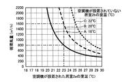
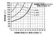
図5は、本発明の実施の形態1において循環風量と建物内の温熱環境とを試算した試算結果の一例を表す特性図である。図5において、横軸は空気調和機が設置された居室2aの室温(℃)を示し、縦軸は循環風量Q(m/h)を示す。図5は、式(2)を用いて、延床面積:120m、延床面積に対する空気調和機が設置された居室2aの床面積の割合:30%、延床面積に対する空気調和機が取り付けられていない居室2bの床面積の割合:50%、延床面積に対する非居室3の床面積の割合:20%、循環風路5に接続される部屋の合計の室容積V:230m、外皮平均熱貫流率UA値:0.4W/(m・K)の条件で、冬期の外気0℃時における空気調和機が設置された居室2aおよび空気調和機が取り付けられていない居室2bの室温と、循環風量との関係を試算した結果である。 FIG. 5 is a characteristic diagram showing an example of a trial calculation result of trial calculation of the circulating air volume and the thermal environment in the building in the first embodiment of the present invention. In FIG. 5, the horizontal axis indicates the room temperature (° C.) of the living room 2a in which the air conditioner is installed, and the vertical axis indicates the circulating air volume Q (m 3 / h). FIG. 5 shows, using the equation (2), the total floor area: 120 m 2 , the ratio of the floor area of the living room 2 a where the air conditioner is installed to the total floor area: 30%, and the air conditioner to the total floor area is attached. Ratio of the floor area of the unoccupied room 2b: 50%, ratio of the floor area of the non-living room 3 to the total floor area: 20%, total room volume V of the rooms connected to the circulating air passage 5: 230 m 3 , outer skin Average heat transfer coefficient UA value: room temperature of room 2a with air conditioner installed and room 2b without air conditioner at 0 ° C. outside air in winter under conditions of 0.4 W / (m 2 · K) It is a result of trial calculation of the relationship between the circulating air volume.

図5における3本の特性線において、実線で示した特性線Aは、空気調和機が取り付けられていない居室2bの室温が18℃の場合を表し、破線で示した特性線Bは、空気調和機が取り付けられていない居室2bの室温が20℃の場合を表し、点線で示した特性線Cは、空気調和機が取り付けられていない居室2bの室温が22℃の場合を表している。   Among the three characteristic lines in FIG. 5, a characteristic line A shown by a solid line represents a case where the room temperature of the living room 2b to which the air conditioner is not attached is 18 ° C., and a characteristic line B shown by a broken line is an air conditioner. The room temperature of the living room 2b to which the device is not attached is 20 ° C., and the characteristic line C shown by the dotted line represents the case where the room temperature of the room 2b to which the air conditioner is not attached is 22 ° C.

図5より、冬期に、空気調和機4において、空気調和機が設置された居室2aの室温を23℃に設定し、循環風量を800m/hとした場合には、空気調和機が取り付けられていない居室2bの室温は18℃となる。また、空気調和機4において、空気調和機が設置された居室2aの室温を23℃に設定し、循環風量を1600m/hに倍増した場合には、空気調和機が取り付けられていない居室2bの室温は20℃となる。なお、空気調和機が取り付けられていない居室2bの温度を22℃まで上げようとすると、さらに多くの循環風量が必要となる。すなわち、本実施の形態1にかかる空気調和システムを使用して空気循環させる場合、空気調和機が設置された居室2aの室温が同じ条件でも、循環風量Qを増加させることにより、空気調和機が取り付けられていない居室2bの室温を上昇させることができる。 From FIG. 5, in winter, in the air conditioner 4, when the room temperature of the living room 2 a where the air conditioner is installed is set to 23 ° C. and the circulating air volume is set to 800 m 3 / h, the air conditioner is installed. The room temperature of the unoccupied room 2b is 18 ° C. In the air conditioner 4, when the room temperature of the room 2a in which the air conditioner is installed is set to 23 ° C. and the circulating air volume is doubled to 1600 m 3 / h, the room 2b in which the air conditioner is not installed. Is 20 ° C. If the temperature of the living room 2b to which the air conditioner is not attached is to be raised to 22 ° C., a larger amount of circulating air is required. That is, when air is circulated using the air-conditioning system according to Embodiment 1, even if the room temperature of the living room 2a in which the air-conditioner is installed is the same, the air-conditioner is increased by increasing the circulating air volume Q. It is possible to raise the room temperature of the living room 2b not attached.

つぎに、図5に示した特性図を別の視点で考察する。まず、空気調和機が取り付けられていない居室2bの温度を18℃以上にするために最低限必要な条件を考える。図5において、空気調和機が取り付けられていない居室2bの温度が18℃以上の条件は、実線で示した特性線Aを含む、特性線Aの右上側の領域に対応する。仮に、空気調和機が設置された居室2aの温度の上限を28℃とした場合には、図5より、400m/h程度以上の循環風量が必要であることが分かる。 Next, the characteristic diagram shown in FIG. 5 will be considered from another viewpoint. First, let us consider the minimum necessary conditions for setting the temperature of the living room 2b to which the air conditioner is not attached to 18 ° C. or higher. In FIG. 5, the condition in which the temperature of the living room 2b to which the air conditioner is not attached is 18 ° C. or higher corresponds to a region on the upper right side of the characteristic line A including the characteristic line A indicated by the solid line. If the upper limit of the temperature of the living room 2a where the air conditioner is installed is set to 28 ° C., it can be seen from FIG. 5 that a circulating air volume of about 400 m 3 / h or more is required.

ただし、冬期においては、室温が28℃の空間は暑すぎるため、空気調和機が設置された居室2aを快適にするために空気調和機が設置された居室2aの温度の上限を26℃とした場合を考える。この場合には、空気調和機が取り付けられていない居室2bの温度を18℃以上にするためには、図5より、500m/h程度以上の循環風量が必要であることがわかる。 However, in the winter, since the room where the room temperature is 28 ° C. is too hot, the upper limit of the temperature of the room 2a where the air conditioner is installed is set to 26 ° C. in order to make the room 2a where the air conditioner is installed comfortable. Consider the case. In this case, it can be seen from FIG. 5 that a circulating air volume of about 500 m 3 / h or more is required to raise the temperature of the living room 2b to which the air conditioner is not attached to 18 ° C. or more.

また、冬期においては、室温が26℃の空間は若干暑いため、空気調和機が設置された居室2aをより快適にするために空気調和機が設置された居室2aの温度の上限を24℃とした場合を考える。この場合には、空気調和機が取り付けられていない居室2bの温度を18℃以上にするためには、図5より、700m/h程度以上の循環風量が必要であることがわかる。 In the winter season, since the room having a room temperature of 26 ° C. is slightly hot, the upper limit of the temperature of the room 2a in which the air conditioner is installed is set to 24 ° C. in order to make the room 2a in which the air conditioner is installed more comfortable. Consider the case. In this case, it can be seen from FIG. 5 that a circulating air volume of about 700 m 3 / h or more is required in order to make the temperature of the living room 2b to which the air conditioner is not attached set to 18 ° C. or more.

したがって、図5に示す試算結果においては、冬期において空気調和機が取り付けられていない居室2bの温度を18℃以上にするために、循環風量を増加させることにより空気調和機が設置された居室2aを快適にするために空気調和機が設置された居室2aの温度の上限を任意の温度に設定可能であることが分かる。   Therefore, according to the calculation results shown in FIG. 5, in order to increase the temperature of the living room 2b, to which the air conditioner is not installed, to 18 ° C. or higher in winter, the circulating air volume is increased to increase the circulating air flow in the living room 2a, in which the air conditioner is installed. It can be understood that the upper limit of the temperature of the living room 2a in which the air conditioner is installed can be set to an arbitrary temperature in order to make the room comfortable.

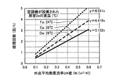
図6は、本発明の実施の形態1において図5に示す外皮平均熱貫流率UA値:0.4W/(m・K)の条件における特性図とその他の外皮平均熱貫流率UA値:0.1W/(m・K)以上0.6W/(m・K)以下の条件における試算結果とを基に作成した、外皮性能ごとの必要循環風量を示す特性図である。図6において、横軸は外皮平均熱貫流率UA(W/(m・K))を示し、縦軸は循環回数(回/h)を示している。図6は、外皮平均熱貫流率UA値以外は、図5と同じく、延床面積:120m、延床面積に対する空気調和機が設置された居室2aの床面積の割合:30%、延床面積に対する空気調和機が取り付けられていない居室2bの床面積の割合:50%、延床面積に対する非居室3の床面積の割合:20%、循環風路5に接続される部屋の合計の室容積V:230m、冬期の外気:0℃の条件で、空気調和機が取り付けられていない居室2bの室温を18℃で固定し、外皮平均熱貫流率UA値(W/(m・K))と循環回数との関係を試算した結果である。 FIG. 6 is a characteristic diagram under the condition of outer skin average heat transmission rate UA value: 0.4 W / (m 2 · K) shown in FIG. 5 and other outer skin average heat transmission rate UA values according to Embodiment 1 of the present invention: 0.1 W / created based on the calculation results in (m 2 · K) or more 0.6W / (m 2 · K) the following condition is a characteristic diagram showing the required amount of circulating air per skin performance. In FIG. 6, the horizontal axis represents the average skin heat transfer rate UA (W / (m 2 · K)), and the vertical axis represents the number of circulations (times / h). 6 is the same as FIG. 5 except for the average hull heat transfer coefficient UA value, the total floor area: 120 m 2 , the ratio of the floor area of the living room 2a where the air conditioner is installed to the total floor area: 30%, The ratio of the floor area of the living room 2b to which the air conditioner is not attached to the area: 50%, the ratio of the floor area of the non-living room 3 to the total floor area: 20%, and the total number of the rooms connected to the circulation wind path 5 Under the conditions of volume V: 230 m 3 , and outside air in winter: 0 ° C., the room temperature of the living room 2 b to which the air conditioner is not attached is fixed at 18 ° C., and the hull average heat transmission coefficient UA value (W / (m 2 · K) This is the result of trial calculation of the relationship between)) and the number of circulations.

図6における3本の特性線において、実線で示した特性線Dは、空気調和機が設置された居室2aの室温が28℃の場合を表し、破線で示した特性線Eは、空気調和機が設置された居室2aの室温が26℃の場合を表し、点線で示した特性線Fは、空気調和機が設置された居室2aの室温が24℃の場合を表している。   Among the three characteristic lines in FIG. 6, a characteristic line D indicated by a solid line indicates a case where the room temperature of the living room 2a where the air conditioner is installed is 28 ° C., and a characteristic line E indicated by a broken line indicates an air conditioner. Represents the case where the room temperature of the living room 2a where is installed is 26 ° C., and the characteristic line F shown by the dotted line represents the case where the room temperature of the living room 2a where the air conditioner is installed is 24 ° C.

図6より、空気調和機が設置された居室2aの室温をそれぞれ28℃以下、26℃以下、または24℃以下にするために必要な循環回数を読み取ることができる。そして、読み取った循環回数から循環風量Qを算出することができる。また、循環回数と外皮平均熱貫流率UA値との関係は原点を通る線形であることから、すなわち循環風量Qと外皮平均熱貫流率UA値の関係は原点を通る線形であることから、空気調和機が設置された居室2aの室温の条件毎に、図6に示す外皮平均熱貫流率UA値(W/(m・K))と循環回数との関係を示す特性線の傾き、すなわち特性線の線形近似式の傾きを求めることで、必要な循環回数を見積もることができる。そして、必要な循環回数を見積もることで、必要な循環風量Qを見積もることができる。 From FIG. 6, it is possible to read the number of circulations necessary for setting the room temperature of the living room 2 a in which the air conditioner is installed to 28 ° C. or lower, 26 ° C. or lower, or 24 ° C. or lower, respectively. Then, the circulation air volume Q can be calculated from the read number of circulations. In addition, since the relationship between the number of circulations and the average skin heat transfer rate UA value is linear passing through the origin, that is, the relationship between the circulating air flow Q and the average skin heat transfer rate UA value is linear through the origin, the air For each condition of the room temperature of the living room 2a in which the harmony device is installed, the slope of the characteristic line indicating the relationship between the hull average heat transmission coefficient UA value (W / (m 2 · K)) and the number of circulations shown in FIG. The required number of circulations can be estimated by obtaining the slope of the linear approximation of the characteristic line. Then, by estimating the required number of circulations, the required circulation air volume Q can be estimated.

たとえば図6において横軸をxとし、縦軸をyとすると、特性線Dの線形近似式は、y=4.511xとなり、特性線Dの線形近似式の傾きは、4.511となる。また、特性線Eの線形近似式は、y=5.643xとなり、特性線Eの線形近似式の傾きは、5.643となる。また、特性線Fの線形近似式は、y=7.526xとなり、特性線Fの線形近似式の傾きは、7.526となる。そこで、本実施の形態1においては、この特性線の線形近似式の傾きを、表2、表3および表4に示す係数aに設定した。   For example, assuming that the horizontal axis is x and the vertical axis is y in FIG. 6, the linear approximation of the characteristic line D is y = 4.511x, and the slope of the linear approximation of the characteristic line D is 4.511. The linear approximation of the characteristic line E is y = 5.643x, and the slope of the linear approximation of the characteristic line E is 5.643. In addition, the linear approximation of the characteristic line F is y = 7.526x, and the slope of the linear approximation of the characteristic line F is 7.526. Therefore, in the first embodiment, the slope of the linear approximation of the characteristic line is set to the coefficient a shown in Tables 2, 3, and 4.

図7は、本発明の実施の形態1において循環風量と建物内の温熱環境とを図6と異なる条件で試算した外皮性能ごとの必要循環風量を示す特性図である。図7が図6と異なる点は、延床面積:80m、循環風路5に接続される部屋の合計の室容積V:154m、の2点である。循環風路5に接続される部屋の合計の室容積Vは、前述の通り天井高を固定しており、延床面積に比例する。したがって、図7の特性図における条件は、実質的には延床面積のみを図6の特性図における条件から変化させている。 FIG. 7 is a characteristic diagram showing the required circulating air volume for each outer skin performance, which is obtained by tentatively calculating the circulating air volume and the thermal environment in the building in the first embodiment of the present invention under conditions different from those in FIG. FIG. 7 differs from FIG. 6 in two points: a total floor area: 80 m 2 , and a total room volume V of a room connected to the circulation air passage 5: 154 m 3 . The total room volume V of the rooms connected to the circulation air passage 5 has a fixed ceiling height as described above, and is proportional to the total floor area. Therefore, the condition in the characteristic diagram of FIG. 7 is that only the total floor area is substantially changed from the condition in the characteristic diagram of FIG.

図7において実線で示した特性線Daは、図6における特性線Dに対応しており、空気調和機が設置された居室2aの室温が28℃の場合を表している。図7において破線で示した特性線Eaは、図6における特性線Eに対応しており、空気調和機が設置された居室2aの室温が26℃の場合を表している。図7において点線で示した特性線Faは、図6における特性線Fに対応しており、空気調和機が設置された居室2aの室温が24℃の場合を表している。   The characteristic line Da indicated by a solid line in FIG. 7 corresponds to the characteristic line D in FIG. 6, and shows a case where the room temperature of the living room 2a in which the air conditioner is installed is 28 ° C. The characteristic line Ea indicated by a broken line in FIG. 7 corresponds to the characteristic line E in FIG. 6, and represents a case where the room temperature of the living room 2a in which the air conditioner is installed is 26 ° C. A characteristic line Fa indicated by a dotted line in FIG. 7 corresponds to the characteristic line F in FIG. 6, and represents a case where the room temperature of the living room 2a in which the air conditioner is installed is 24 ° C.

特性線Daの線形近似式は、y=5.132xとなり、特性線Daの線形近似式の傾きは、5.132となる。ここで、図7と図6と比較すると、図6の特性線Dは、図7の特性線Daよりも全ての外皮平均熱貫流率UA値において常に小さい。つまり、延床面積80m以上120m以下においては、必要な循環風量Qは少なくとも図6から読み取れる循環回数から見積もれる循環風量以上であり、係数aの値は、4.511以上である必要がある。このように、係数aは、適宜設定した延床面積の範囲の中で、できるだけ小さい値を選択している。なお、空気調和機が設置された居室2aの室温が26℃の場合および空気調和機が設置された居室2aの室温が24℃の場合も、同様である。 The linear approximation of the characteristic line Da is y = 5.132x, and the slope of the linear approximation of the characteristic line Da is 5.132. Here, comparing FIG. 7 with FIG. 6, the characteristic line D in FIG. 6 is always smaller than the characteristic line Da in FIG. In other words, when the total floor area is 80 m 2 or more and 120 m 2 or less, the required circulation air volume Q is at least the circulation air volume estimated from the number of circulations read from FIG. 6, and the value of the coefficient a needs to be 4.511 or more. is there. As described above, the coefficient a is selected as small as possible in the range of the total floor area which is appropriately set. The same applies to the case where the room temperature of the living room 2a where the air conditioner is installed is 26 ° C and the case where the room temperature of the living room 2a where the air conditioner is installed is 24 ° C.

図8は、本発明の実施の形態1において循環風量と建物内の温熱環境とを図6と異なる条件で試算した外皮性能ごとの必要循環風量を示す特性図である。図8が図6と異なる点は、延床面積に対する空気調和機が設置された居室2aの床面積の割合:40%、延床面積に対する空気調和機が取り付けられていない居室2bの床面積の割合:40%、の2点である。延床面積に対する空気調和機が取り付けられていない居室2bの床面積の割合は、前述のとおり延床面積に対する非居室3の床面積の割合を固定しており、延床面積に対する空気調和機が設置された居室2aの床面積の割合に反比例する。したがって、図8の特性図における条件は、実質的には延床面積に対する空気調和機が設置された居室2aの床面積の割合のみを図6の特性図における条件から変化させている。   FIG. 8 is a characteristic diagram showing the required circulating air volume for each of the outer skin performances obtained by trially calculating the circulating air volume and the thermal environment in the building in the first embodiment of the present invention under conditions different from those in FIG. 8 is different from FIG. 6 in that the ratio of the floor area of the living room 2a in which the air conditioner is installed to the total floor area is 40%, and the floor area of the living room 2b in which the air conditioner is not installed is based on the total floor area. Ratio: 40%. As described above, the ratio of the floor area of the non-living room 3 to the total floor area is fixed, and the ratio of the floor area of the non-living room 3 to the total floor area is fixed. It is inversely proportional to the ratio of the floor area of the installed living room 2a. Therefore, the condition in the characteristic diagram of FIG. 8 substantially changes only the ratio of the floor area of the living room 2a in which the air conditioner is installed to the total floor area from the condition in the characteristic diagram of FIG.

図8において実線で示した特性線Dbは、図6における特性線Dに対応しており、空気調和機が設置された居室2aの室温が28℃の場合を表している。図8において破線で示した特性線Ebは、図6における特性線Eに対応しており、空気調和機が設置された居室2aの室温が26℃の場合を表している。図8において点線で示した特性線Fbは、図6における特性線Fに対応しており、空気調和機が設置された居室2aの室温が24℃の場合を表している。   The characteristic line Db shown by a solid line in FIG. 8 corresponds to the characteristic line D in FIG. 6, and shows a case where the room temperature of the living room 2a in which the air conditioner is installed is 28 ° C. A characteristic line Eb indicated by a broken line in FIG. 8 corresponds to the characteristic line E in FIG. 6, and shows a case where the room 2a in which the air conditioner is installed has a room temperature of 26 ° C. A characteristic line Fb indicated by a dotted line in FIG. 8 corresponds to the characteristic line F in FIG. 6, and represents a case where the room temperature of the living room 2a in which the air conditioner is installed is 24 ° C.

図8において実線で示した特性線Dbの線形近似式は、y=3.615xとなり、特性線Dの線形近似式の傾きは、3.615となる。ここで、図8と図6と比較すると、図6の特性線Dは、図8の特性線Dbよりも全ての外皮平均熱貫流率UA値において常に小さい。つまり、延床面積に対する空気調和機が設置された居室2aの床面積の割合30%以上40%以下においては、必要な循環風量Qは少なくとも図8から読み取れる循環回数から見積もれる循環風量以上であり、係数aの値は、3.615以上である必要がある。このように、係数aは、適宜設定した延床面積に対する空気調和機が設置された居室2aの床面積の割合の範囲の中で、係数aができるだけ小さい値を選択している。   In FIG. 8, the linear approximation of the characteristic line Db indicated by the solid line is y = 3.615x, and the slope of the linear approximation of the characteristic line D is 3.615. Here, comparing FIG. 8 with FIG. 6, the characteristic line D in FIG. 6 is always smaller than the characteristic line Db in FIG. That is, in the ratio of the floor area of the living room 2a in which the air conditioner is installed to the total floor area of 30% or more and 40% or less, the required circulation air volume Q is at least the circulation air volume estimated from the number of circulations read from FIG. , Coefficient a must be equal to or greater than 3.615. As described above, the coefficient a is selected as small as possible in the range of the ratio of the floor area of the living room 2a in which the air conditioner is installed to the appropriately set total floor area.

次に、夏期の冷房時における係数aの設定根拠について説明する。   Next, the basis for setting the coefficient a during cooling in summer will be described.

図9は、本発明の実施の形態1において循環風量と建物内の温熱環境とを試算した試算結果の一例を表す特性図である。図9は、式(2)を用いて、延床面積:120m、延床面積に対する空気調和機が設置された居室2aの床面積の割合:30%、延床面積に対する空気調和機が取り付けられていない居室2bの床面積の割合:50%、延床面積に対する非居室3の床面積の割合:20%、循環風路5に接続される部屋の合計の室容積V:230m、外皮平均熱貫流率UA値:0.4W/(m・K)の条件で、夏期の外気35℃時における空気調和機が設置された居室2aおよび空気調和機が取り付けられていない居室2bの室温と、循環風量との関係を試算した結果である。 FIG. 9 is a characteristic diagram illustrating an example of a trial calculation result of trial calculation of the circulating air volume and the thermal environment in the building in the first embodiment of the present invention. FIG. 9 shows, using the equation (2), the total floor area: 120 m 2 , the ratio of the floor area of the living room 2 a in which the air conditioner is installed to the total floor area: 30%, and the air conditioner to the total floor area is attached. The ratio of the floor area of the unoccupied room 2b: 50%, the ratio of the floor area of the non-living room 3 to the total floor area: 20%, the total room volume V of the rooms connected to the circulation wind path 5: 230 m 3 , and the outer skin Average heat transfer rate UA value: Room temperature of living room 2a with air conditioner and living room 2b without air conditioner at 35 ° C. in outside air in summer in the condition of 0.4 W / (m 2 · K) It is a result of trial calculation of the relationship between the circulating air volume.

図9における3本の特性線において、実線で示した特性線Gは、空気調和機が取り付けられていない居室2bの室温が28℃の場合を表し、破線で示した特性線Hは、空気調和機が取り付けられていない居室2bの室温が26℃の場合を表し、点線で示した特性線Iは、空気調和機が取り付けられていない居室2bの室温が24℃の場合を表している。   Among the three characteristic lines in FIG. 9, a characteristic line G indicated by a solid line indicates a case where the room temperature of the living room 2 b to which the air conditioner is not attached is 28 ° C., and a characteristic line H indicated by a broken line indicates the air conditioning. The room temperature of the room 2b to which the air conditioner is not mounted is 26 ° C., and the characteristic line I indicated by the dotted line represents the case where the room temperature of the room 2b to which the air conditioner is not mounted is 24 ° C.

図9より、夏期に、空気調和機4において、空気調和機が設置された居室2aの室温を24℃に設定し、循環風量を1800m/hとした場合には、空気調和機が取り付けられていない居室2bの室温は28℃となる。 From FIG. 9, in the summer, in the air conditioner 4, when the room temperature of the living room 2 a where the air conditioner is installed is set to 24 ° C. and the circulating air volume is 1800 m 3 / h, the air conditioner is installed. The room temperature of the unoccupied room 2b is 28 ° C.

つぎに、図9に示した特性図を別の視点で考察する。まず、空気調和機が取り付けられていない居室2bの温度を28℃以下にするために最低限必要な条件を考える。図9において、空気調和機が取り付けられていない居室2bの温度が28℃以下の条件は、実線で示した特性線Gを含む、特性線Gの左上側の領域に対応する。仮に、空気調和機が設置された居室2aの温度の下限を18℃とした場合には、図9より、700m/h程度以上の循環風量が必要であることが分かる。 Next, the characteristic diagram shown in FIG. 9 will be considered from another viewpoint. First, the minimum necessary conditions for reducing the temperature of the living room 2b to which the air conditioner is not attached to 28 ° C. or less will be considered. In FIG. 9, the condition in which the temperature of the living room 2b to which the air conditioner is not attached is 28 ° C. or lower corresponds to the upper left region of the characteristic line G including the characteristic line G indicated by the solid line. If the lower limit of the temperature of the living room 2a in which the air conditioner is installed is set to 18 ° C., it can be seen from FIG. 9 that a circulating air volume of about 700 m 3 / h or more is required.

ただし、夏期においては、室温が18℃の空間は寒すぎるため、空気調和機が設置された居室2aを快適にするために空気調和機が設置された居室2aの温度の下限を20℃とした場合を考える。この場合には、空気調和機が取り付けられていない居室2bの温度を28℃以下にするためには、図9より、900m/h程度以上の循環風量が必要であることがわかる。 However, in summer, since the room having a room temperature of 18 ° C. is too cold, the lower limit of the temperature of the room 2a in which the air conditioner is installed is set to 20 ° C. in order to make the room 2a in which the air conditioner is installed comfortable. Consider the case. In this case, it can be seen from FIG. 9 that a circulating air volume of about 900 m 3 / h or more is required in order to lower the temperature of the living room 2b to which the air conditioner is not attached to 28 ° C. or less.

また、夏期においては、室温が20℃の空間は若干寒いため、空気調和機が設置された居室2aをより快適にするために空気調和機が設置された居室2aの温度の下限を22℃とした場合を考える。この場合には、空気調和機が取り付けられていない居室2bの温度を28℃以下にするためには、図9より、1200m/h程度以上の循環風量が必要であることがわかる。 Also, in the summer, since the room having a room temperature of 20 ° C. is slightly cold, the lower limit of the temperature of the room 2 a where the air conditioner is installed is set to 22 ° C. in order to make the room 2 a where the air conditioner is installed more comfortable. Consider the case. In this case, it can be seen from FIG. 9 that a circulating air volume of about 1200 m 3 / h or more is necessary in order to lower the temperature of the living room 2 b to which the air conditioner is not attached to 28 ° C. or less.

したがって、図9に示す試算結果においては、夏期において空気調和機が取り付けられていない居室2bの温度を28℃以下にするために、循環風量を増加させることにより空気調和機が設置された居室2aを快適にするために空気調和機が設置された居室2aの温度の下限を任意の温度に設定可能であることが分かる。   Therefore, in the calculation results shown in FIG. 9, in order to reduce the temperature of the living room 2 b in which the air conditioner is not installed in the summer to 28 ° C. or less, the living room 2 a in which the air conditioner is installed by increasing the circulating air volume is shown. It can be seen that the lower limit of the temperature of the living room 2a in which the air conditioner is installed can be set to an arbitrary temperature in order to make the air conditioner comfortable.

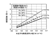
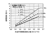
図10は、本発明の実施の形態1において図9に示す外皮平均熱貫流率UA値:0.4W/(m・K)の条件における特性図とその他の外皮平均熱貫流率UA値:0.1W/(m・K)以上0.6W/(m・K)以下の条件における試算結果とを基に作成した、外皮性能ごとの必要循環風量を示す特性図である。図10は、外皮平均熱貫流率UA値以外は、図9と同じく、延床面積:120m、延床面積に対する空気調和機が設置された居室2aの床面積の割合:30%、延床面積に対する空気調和機が取り付けられていない居室2bの床面積の割合:50%、延床面積に対する非居室3の床面積の割合:20%、循環風路5に接続される部屋の合計の室容積V:230m、夏期の外気:35℃の条件で、空気調和機が取り付けられていない居室2bの室温を28℃で固定し、外皮平均熱貫流率UA値(W/(m・K))と循環回数との関係を試算した結果である。 FIG. 10 is a characteristic diagram under the condition of the outer skin average heat transmission rate UA value of 0.4 W / (m 2 · K) shown in FIG. 9 and other outer skin mean heat transmission rate UA values in Embodiment 1 of the present invention: 0.1 W / created based on the calculation results in (m 2 · K) or more 0.6W / (m 2 · K) the following condition is a characteristic diagram showing the required amount of circulating air per skin performance. FIG. 10 is the same as FIG. 9 except for the hull average heat transfer coefficient UA value, the total floor area: 120 m 2 , the ratio of the floor area of the living room 2 a where the air conditioner is installed to the total floor area: 30%, The ratio of the floor area of the living room 2b to which the air conditioner is not attached to the area: 50%, the ratio of the floor area of the non-living room 3 to the total floor area: 20%, and the total number of the rooms connected to the circulation wind path 5 Under the conditions of a volume V of 230 m 3 and summer outside air: 35 ° C., the room temperature of the living room 2 b to which the air conditioner was not attached was fixed at 28 ° C., and the average skin heat transfer coefficient UA value (W / (m 2 · K) This is the result of trial calculation of the relationship between)) and the number of circulations.

図10における3本の特性線において、実線で示した特性線Jは、空気調和機が設置された居室2aの室温が18℃の場合を表し、破線で示した特性線Kは、空気調和機が設置された居室2aの室温が20℃の場合を表し、点線で示した特性線Lは、空気調和機が設置された居室2aの室温が22℃の場合を表している。   Among the three characteristic lines in FIG. 10, a characteristic line J indicated by a solid line represents a case where the room temperature of the living room 2 a where the air conditioner is installed is 18 ° C., and a characteristic line K indicated by a broken line is an air conditioner. Represents a case where the room temperature of the living room 2a where is installed is 20 ° C., and a characteristic line L indicated by a dotted line represents a case where the room temperature of the living room 2a where the air conditioner is installed is 22 ° C.

図10より、空気調和機が設置された居室2aの室温をそれぞれ18℃以上、20℃以上、または22℃以上にするために必要な循環回数を読み取ることができる。そして、読み取った循環回数から循環風量Qを算出することができる。また、循環回数と外皮平均熱貫流率UA値との関係は原点を通る線形であることから、すなわち循環風量Qと外皮平均熱貫流率UA値の関係は原点を通る線形であることから、空気調和機が設置された居室2aの室温の条件毎に、図10に示す外皮平均熱貫流率UA値(W/(m・K))と循環回数との関係を示す特性線の傾き、すなわち特性線の線形近似式の傾きを求めることで、必要な循環回数を見積もることができる。そして、必要な循環回数を見積もることで、必要な循環風量Qを見積もることができる。 From FIG. 10, it is possible to read the number of circulations necessary for setting the room temperature of the living room 2 a in which the air conditioner is installed to 18 ° C. or higher, 20 ° C. or higher, or 22 ° C. or higher, respectively. Then, the circulation air volume Q can be calculated from the read number of circulations. In addition, since the relationship between the number of circulations and the average skin heat transfer rate UA value is linear passing through the origin, that is, the relationship between the circulating air flow Q and the average skin heat transfer rate UA value is linear through the origin, the air For each condition of the room temperature of the living room 2a in which the harmony device is installed, the slope of the characteristic line indicating the relationship between the hull average heat transmission coefficient UA value (W / (m 2 · K)) and the number of circulations shown in FIG. The required number of circulations can be estimated by obtaining the slope of the linear approximation of the characteristic line. Then, by estimating the required number of circulations, the required circulation air volume Q can be estimated.

たとえば図10において横軸をxとし、縦軸をyとすると、特性線Jの線形近似式は、y=7.905xとなり、特性線Jの線形近似式の傾きは、7.905となる。また、特性線Kの線形近似式は、y=9.880xとなり、特性線Kの線形近似式の傾きは、9.880となる。また、特性線Lの線形近似式は、y=13.165xとなり、特性線Lの線形近似式の傾きは、13.165となる。そこで、本実施の形態1においては、この特性線の線形近似式の傾きを、表2、表3および表4に示す係数aに設定した。   For example, assuming that the horizontal axis is x and the vertical axis is y in FIG. 10, the linear approximation of the characteristic line J is y = 7.905x, and the slope of the linear approximation of the characteristic line J is 7.905. Also, the linear approximation of the characteristic line K is y = 9.880x, and the slope of the linear approximation of the characteristic line K is 9.880. The linear approximation of the characteristic line L is y = 13.165x, and the slope of the linear approximation of the characteristic line L is 13.165. Therefore, in the first embodiment, the slope of the linear approximation of the characteristic line is set to the coefficient a shown in Tables 2, 3, and 4.

図11は、本発明の実施の形態1において循環風量と建物内の温熱環境とを図10と異なる条件で試算した外皮性能ごとの必要循環風量を示す特性図である。図11が図10と異なる点は、延床面積:80m、循環風路5に接続される部屋の合計の室容積V:154m、の2点である。循環風路5に接続される部屋の合計の室容積Vは、前述の通り天井高を固定しており、延床面積に比例する。したがって、図11の特性図における条件は、実質的には延床面積のみを図10の特性図における条件から変化させている。 FIG. 11 is a characteristic diagram showing the required circulating air volume for each of the outer skin performances obtained by trially calculating the circulating air volume and the thermal environment in the building in the first embodiment of the present invention under conditions different from those in FIG. FIG. 11 differs from FIG. 10 in two points: the total floor area: 80 m 2 , and the total room volume V of the rooms connected to the circulation air passage 5: 154 m 3 . The total room volume V of the rooms connected to the circulation air passage 5 has a fixed ceiling height as described above, and is proportional to the total floor area. Therefore, the conditions in the characteristic diagram of FIG. 11 substantially change only the total floor area from the conditions in the characteristic diagram of FIG.

図11において実線で示した特性線Jaは、図10における特性線Jに対応しており、空気調和機が設置された居室2aの室温が18℃の場合を表している。図11において破線で示した特性線Kaは、図10における特性線Kに対応しており、空気調和機が設置された居室2aの室温が20℃の場合を表している。図10において点線で示した特性線Laは、図10における特性線Lに対応しており、空気調和機が設置された居室2aの室温が22℃の場合を表している。   A characteristic line Ja indicated by a solid line in FIG. 11 corresponds to the characteristic line J in FIG. 10, and represents a case where the room temperature of the living room 2a in which the air conditioner is installed is 18 ° C. The characteristic line Ka indicated by a broken line in FIG. 11 corresponds to the characteristic line K in FIG. 10 and represents a case where the room 2a in which the air conditioner is installed has a room temperature of 20 ° C. A characteristic line La indicated by a dotted line in FIG. 10 corresponds to the characteristic line L in FIG. 10 and shows a case where the room temperature of the living room 2a in which the air conditioner is installed is 22 ° C.

図11において実線で示した特性線Jaの線形近似式は、y=8.989xとなり、特性線Jaの線形近似式の傾きは、8.989となる。ここで、図11と図10と比較すると、図10の特性線Jは、図11の特性線Jaよりも全ての外皮平均熱貫流率UA値において常に小さい。つまり、延床面積80m以上120m以下においては、必要な循環風量Qは少なくとも図10から読み取れる循環回数から見積もれる循環風量以上であり、係数aの値は、7.905以上である必要がある。このように、係数aは、夏期においても、適宜設定した延床面積の範囲の中で、係数aができるだけ小さい値を選択している。 In FIG. 11, the linear approximation of the characteristic line Ja indicated by the solid line is y = 8.989x, and the slope of the linear approximation of the characteristic line Ja is 8.989. Here, comparing FIG. 11 with FIG. 10, the characteristic line J in FIG. 10 is always smaller than the characteristic line Ja in FIG. In other words, when the total floor area is 80 m 2 or more and 120 m 2 or less, the required circulation air volume Q is at least the circulation air volume estimated from the number of circulations read from FIG. 10, and the value of the coefficient a needs to be 7.905 or more. is there. As described above, the coefficient a is selected as small as possible within the range of the appropriately set total floor area even in the summer.

図12は、本発明の実施の形態1において循環風量と建物内の温熱環境とを図10と異なる条件で試算した外皮性能ごとの必要循環風量を示す特性図である。図12が図10と異なる点は、延床面積に対する空気調和機が設置された居室2aの床面積の割合:40%、延床面積に対する空気調和機が取り付けられていない居室2bの床面積の割合:40%、の2点である。延床面積に対する空気調和機が取り付けられていない居室2bの床面積の割合は、前述のとおり延床面積に対する非居室3の床面積の割合を固定しており、延床面積に対する空気調和機が設置された居室2aの床面積の割合に反比例する。したがって、図12の特性図における条件は、実質的には延床面積に対する空気調和機が設置された居室2aの床面積の割合のみを図10の特性図における条件から変化させている。   FIG. 12 is a characteristic diagram showing the required circulating air volume for each outer skin performance, which is obtained by trially calculating the circulating air volume and the thermal environment in the building in the first embodiment of the present invention under conditions different from those in FIG. FIG. 12 differs from FIG. 10 in that the ratio of the floor area of the living room 2a in which the air conditioner is installed to the total floor area: 40%, and the floor area of the living room 2b in which the air conditioner is not installed relative to the total floor area. Ratio: 40%. As described above, the ratio of the floor area of the non-living room 3 to the total floor area is fixed, and the ratio of the floor area of the non-living room 3 to the total floor area is fixed. It is inversely proportional to the ratio of the floor area of the installed living room 2a. Therefore, the condition in the characteristic diagram of FIG. 12 substantially changes only the ratio of the floor area of the living room 2a in which the air conditioner is installed to the total floor area from the condition in the characteristic diagram of FIG.

図12において実線で示した特性線Jbは、図10における特性線Jに対応しており、空気調和機が設置された居室2aの室温が18℃の場合を表している。図12において破線で示した特性線Kbは、図10における特性線Kに対応しており、空気調和機が設置された居室2aの室温が20℃の場合を表している。図12において点線で示した特性線Lbは、図10における特性線Lに対応しており、空気調和機が設置された居室2aの室温が22℃の場合を表している。   A characteristic line Jb indicated by a solid line in FIG. 12 corresponds to the characteristic line J in FIG. 10, and shows a case where the room temperature of the living room 2a in which the air conditioner is installed is 18 ° C. A characteristic line Kb indicated by a broken line in FIG. 12 corresponds to the characteristic line K in FIG. 10 and represents a case where the room 2a in which the air conditioner is installed has a room temperature of 20 ° C. A characteristic line Lb indicated by a dotted line in FIG. 12 corresponds to the characteristic line L in FIG. 10, and shows a case where the room temperature of the living room 2a in which the air conditioner is installed is 22 ° C.

図12において実線で示した特性線Jbの線形近似式は、y=6.323xとなり、特性線Jbの線形近似式の傾きは、6.323となる。ここで、図12と図10と比較すると、図12の特性線Jbは、図10の特性線Jよりも全ての外皮平均熱貫流率UA値において常に小さい。つまり、延床面積に対する空気調和機が設置された居室2aの床面積の割合30%以上40%以下においては、必要な循環風量Qは少なくとも図12に示す循環風量以上であり、係数aの値は、6.323以上である必要がある。このように、係数aは、適宜設定した延床面積に対する空気調和機が設置された居室2aの床面積の割合の範囲の中で、係数aができるだけ小さい値を選択している。   In FIG. 12, the linear approximation of the characteristic line Jb indicated by the solid line is y = 6.323x, and the slope of the linear approximation of the characteristic line Jb is 6.323. Here, when comparing FIG. 12 with FIG. 10, the characteristic line Jb in FIG. 12 is always smaller than the characteristic line J in FIG. That is, when the ratio of the floor area of the living room 2a in which the air conditioner is installed to the total floor area is 30% or more and 40% or less, the required circulating air volume Q is at least the circulating air volume shown in FIG. Needs to be 6.323 or more. As described above, the coefficient a is selected as small as possible in the range of the ratio of the floor area of the living room 2a in which the air conditioner is installed to the appropriately set total floor area.

つぎに、循環用送風機6の運転について説明する。表2、表3および表4に示す情報のうち建物1に適合する係数aの情報、断熱部材7による建物1の外皮平均熱貫流率UA値(UA:W/(m・K))の情報、循環風路5に接続される部屋の合計の室容積(V:m)の情報、およびこれらから得られる式(1)の情報は、空気調和機4の設置時に予め送風機操作端末60の記憶部64に記憶させておく。 Next, the operation of the circulation blower 6 will be described. Among the information shown in Tables 2, 3, and 4, information on the coefficient a that is compatible with the building 1 and the UA value (UA: W / (m 2 · K)) of the average heat transfer coefficient of the outer skin of the building 1 by the heat insulating member 7 The information, the information on the total room volume (V: m 3 ) of the rooms connected to the circulating air passage 5, and the information of the formula (1) obtained therefrom are obtained beforehand when the air conditioner 4 is installed. Is stored in the storage unit 64.

送風機操作端末60の端末制御部63は、空気調和機4の運転時に、空気調和機4の運転が暖房であるか冷房であるかの運転の種別を示す運転種別情報と、空気調和機4における空気調和機が設置された居室2aの設定温度の情報と、を空気調和機4から取得する。   The terminal control unit 63 of the blower operation terminal 60 operates at the time of operation of the air conditioner 4, the operation type information indicating the operation type of the operation of the air conditioner 4 as heating or cooling, and the operation type information in the air conditioner 4. Information on the set temperature of the living room 2 a where the air conditioner is installed is acquired from the air conditioner 4.

冬期における空気調和機4の暖房運転時の係数aの取得について説明する。端末制御部63は、空気調和機4から取得した運転種別情報と設定温度の情報とに基づいて、空気調和機が取り付けられていない居室2bの室温を18℃以上にするための係数aを表2、表3および表4から選択する。   The acquisition of the coefficient a during the heating operation of the air conditioner 4 in winter will be described. The terminal control unit 63 displays a coefficient a for setting the room temperature of the living room 2b to which the air conditioner is not attached to 18 ° C. or higher based on the operation type information and the set temperature information acquired from the air conditioner 4. 2, select from Table 3 and Table 4.

たとえば、運転種別が暖房であり、設定温度が26℃より高く28℃以下である場合には、端末制御部63は、係数aを表2から選択する。運転種別が暖房であり、設定温度が24℃より高く26℃以下である場合には、端末制御部63は、係数aを表3から選択する。運転種別が暖房であり、設定温度が24℃以下である場合には、端末制御部63は、係数aを表4から選択する。   For example, when the operation type is heating and the set temperature is higher than 26 ° C. and equal to or lower than 28 ° C., the terminal control unit 63 selects the coefficient a from Table 2. When the operation type is heating and the set temperature is higher than 24 ° C. and equal to or lower than 26 ° C., the terminal control unit 63 selects the coefficient a from Table 3. When the operation type is heating and the set temperature is equal to or lower than 24 ° C., the terminal control unit 63 selects the coefficient a from Table 4.

つぎに、夏期における空気調和機4の冷房運転時の係数aの取得について説明する。端末制御部63は、空気調和機4から取得した運転種別情報と設定温度の情報とに基づいて、空気調和機が取り付けられていない居室2bの室温を28℃以下にするための係数aを表2、表3および表4から選択する。   Next, the acquisition of the coefficient a during the cooling operation of the air conditioner 4 in the summer will be described. The terminal control unit 63 displays a coefficient a for setting the room temperature of the living room 2b to which the air conditioner is not attached to 28 ° C. or lower based on the operation type information and the set temperature information acquired from the air conditioner 4. 2, select from Table 3 and Table 4.

たとえば、運転種別が冷房であり、設定温度が18℃以上であり20℃未満である場合には、端末制御部63は、係数aを表2から選択する。運転種別が冷房であり、設定温度が20℃以上であり22℃未満である場合には、端末制御部63は、係数aを表3から選択する。運転種別が冷房であり、設定温度が22℃以上である場合には、端末制御部63は、係数aを表4から選択する。   For example, when the operation type is cooling and the set temperature is equal to or higher than 18 ° C. and lower than 20 ° C., the terminal control unit 63 selects the coefficient a from Table 2. When the operation type is cooling and the set temperature is equal to or higher than 20 ° C. and lower than 22 ° C., the terminal control unit 63 selects the coefficient a from Table 3. When the operation type is cooling and the set temperature is 22 ° C. or higher, the terminal control unit 63 selects the coefficient a from Table 4.

表2、表3、表4に示すように、空気調和機4の運転が暖房であるか冷房であるかの運転の種別を示す運転種別と、建物1の延床面積と、延床面積に対する空気調和機が設置された居室2aの床面積の割合とが係数aと関連付けられた、係数aを判定するための判定条件を、空気調和機4における空気調和機が設置された居室2aの設定温度毎に有することで、現在の空気調和機が設置された居室2aの状況に対応した適切な循環風量の下限値を算出することができる。   As shown in Table 2, Table 3, and Table 4, the operation type indicating whether the operation of the air conditioner 4 is heating or cooling, the total floor area of the building 1, and the total floor area The determination condition for determining the coefficient a in which the ratio of the floor area of the living room 2a where the air conditioner is installed and the coefficient a is set to the setting of the living room 2a where the air conditioner is installed in the air conditioner 4 By having the temperature for each temperature, it is possible to calculate an appropriate lower limit value of the circulating air flow corresponding to the situation of the living room 2a where the current air conditioner is installed.

なお、式(1)の情報および表2、表3および表4に示す情報の全てを、空気調和機4の設置時に予め送風機操作端末60の記憶部64に記憶させておき、端末制御部63が、入力部61から入力される建物1についての延床面積の情報、および延床面積に対する空気調和機が設置された居室2aの床面積の割合の情報に基づいて、端末制御部63が表2、表3および表4に示す情報から建物1に適合する係数aを取得してもよい。   It should be noted that all of the information of Expression (1) and the information shown in Tables 2, 3 and 4 are stored in advance in the storage unit 64 of the blower operation terminal 60 when the air conditioner 4 is installed, and the terminal control unit 63 The terminal control unit 63 displays a table based on the information on the total floor area of the building 1 input from the input unit 61 and the information on the ratio of the total floor area of the living room 2a where the air conditioner is installed to the total floor area. 2, a coefficient a suitable for the building 1 may be obtained from the information shown in Tables 3 and 4.

端末制御部63は、選択した係数a、断熱部材7による建物1の外皮平均熱貫流率UA値(UA:W/(m・K))の情報、および循環風路5に接続される部屋の合計の室容積(V:m)の情報、を用いて上記式(1)により循環用送風機6の風量Qを算出して、算出した循環用送風機6の風量Qを下限指示循環風量として送風を指示する風量指令を循環用送風機6の送風機制御部32に送信する。すなわち、端末制御部63は、表2、表3、表4に示す、空気調和機4における冷暖房の運転種別と、建物の延床面積と、建物の延床面積に対する第1の居室の床面積の割合と、に対応した係数a(mK/(W・h))と、建物の外皮平均熱貫流率UA(W/(m・K))と、循環風路5に接続される第1の居室と第2の居室との合計の室容積V(m)と、循環用送風機の風量Q(m/h)とが上記式(1)を満たすように循環用送風機6の風量を制御する。 The terminal control unit 63 determines the selected coefficient a, information on the UA value (UA: W / (m 2 · K)) of the average heat transfer coefficient of the skin of the building 1 by the heat insulating member 7, and the room connected to the circulation air passage 5. , The air volume Q of the circulation fan 6 is calculated by the above equation (1) using the information of the total chamber volume (V: m 3 ), and the calculated air volume Q of the circulation fan 6 is set as the lower limit instruction circulation air volume. An air volume command for instructing air blowing is transmitted to the blower controller 32 of the circulation blower 6. That is, the terminal control unit 63 determines the operation type of air conditioning in the air conditioner 4, the total floor area of the building, and the floor area of the first living room with respect to the total floor area of the building, as shown in Tables 2, 3, and 4. And the coefficient a (m 2 K / (W · h)) corresponding to, the average heat transfer coefficient UA of the building skin (W / (m 2 · K)), and connected to the circulation wind path 5. The circulation blower 6 is arranged so that the total room volume V (m 3 ) of the first room and the second room and the air volume Q (m 3 / h) of the circulation blower satisfy the above expression (1). Control the air volume.

循環用送風機6の送風機制御部32は、端末制御部63から送信された風量指令の下限指示循環風量以上の風量で循環用送風機6の送風部31の運転を制御する。なお、循環用送風機6が複数段階の風量に運転可能な場合には、送風機制御部32は、端末制御部63から送信された風量指令の下限指示循環風量を循環用送風機6の風量の下限値として、指示循環風量に近い風量で循環用送風機6の送風部31の運転を制御する。   The blower control unit 32 of the circulation blower 6 controls the operation of the blower unit 31 of the circulation blower 6 at a flow rate equal to or larger than the lower limit circulation flow rate of the flow rate command transmitted from the terminal control unit 63. If the circulation blower 6 can be operated at a plurality of stages of air flow, the blower control unit 32 sets the lower limit instruction circulation air flow of the air flow command transmitted from the terminal control unit 63 to the lower limit of the air flow of the circulation blower 6. The operation of the blower 31 of the circulation blower 6 is controlled at a flow rate close to the instructed circulation flow rate.

なお、たとえば係数aを表2から選択して上記式(1)により循環用送風機6の風量Qが算出された場合、送風機制御部32は、延床面積:80m未満、延床面積に対する空気調和機が設置された居室の床面積の割合:30%以上40%未満の条件から係数a:4.1が選択された場合には、延床面積:80m未満、延床面積に対する空気調和機が設置された居室の床面積の割合:30%未満の条件から係数a:5.1が選択された場合よりも小さい風量で、循環用送風機6の送風部31の運転を制御する。 For example, when the coefficient a is selected from Table 2 and the air volume Q of the circulation blower 6 is calculated according to the above equation (1), the blower control unit 32 determines that the total floor area is less than 80 m 2 , the ratio of floor area of the room in which conditioner is installed: coefficients from the condition of 30% or more and less than 40% a: when 4.1 is selected, total floor area: less than 80 m 2, an air conditioner for floor space The operation of the blower 31 of the circulation blower 6 is controlled with a smaller airflow than when the coefficient a: 5.1 is selected from the condition that the ratio of the floor area of the living room where the machine is installed is less than 30%.

また、たとえば係数aを表2から選択して上記式(1)により循環用送風機6の風量Qが算出された場合、送風機制御部32は、延床面積:80m未満、延床面積に対する空気調和機が設置された居室の床面積の割合:40%以上の条件から係数a:3.0が選択された場合には、延床面積:80m未満、延床面積に対する空気調和機が設置された居室の床面積の割合:30%以上40%未満の条件から係数a:4.1が選択された場合よりも小さい風量で、循環用送風機6の送風部31の運転を制御する。 Further, for example, when the coefficient a is selected from Table 2 and the air volume Q of the circulation blower 6 is calculated by the above equation (1), the blower control unit 32 determines that the total floor area is less than 80 m 2 , the ratio of floor area of the room in which conditioner is installed: coefficient 40% or more of the conditions a: when 3.0 is selected, total floor area: less than 80 m 2, an air conditioner for floor space installation The operation of the blower 31 of the circulation blower 6 is controlled with a smaller airflow than when the coefficient a: 4.1 is selected from the condition of the floor area ratio of the selected living room: 30% or more and less than 40%.

すなわち、延床面積が同じ条件の範囲において延床面積に対する空気調和機が設置された居室の床面積の割合が異なる場合を比べると、送風機制御部32は、小さい係数aが選択された場合には、大きい係数aが選択された場合よりも、小さい風量で、循環用送風機6の送風部31の運転を制御する。これにより、循環用送風機6の省エネルギー化を図りつつ、空気調和機が取り付けられていない居室2bの室温を上げることができる。   That is, compared with the case where the ratio of the floor area of the living room where the air conditioner is installed to the total floor area is different in the range where the total floor area is the same condition, the blower control unit 32 determines that the small coefficient a is selected. Controls the operation of the blower 31 of the circulation blower 6 with a smaller airflow than when a large coefficient a is selected. This makes it possible to raise the room temperature of the living room 2b to which the air conditioner is not attached while saving energy of the circulation blower 6.

端末制御部63は、循環用送風機6の停止を指示する指令を入力部61から受信した場合には、送風機制御部32に対して循環用送風機6の停止の制御を行う。   When the terminal controller 63 receives a command to stop the circulation blower 6 from the input unit 61, the terminal controller 63 controls the blower controller 32 to stop the circulation blower 6.

なお、上記においては、空気調和機が設置された居室2aに1台の空気調和機4が設けられた場合について示したが、空気調和機が設置された居室2aにおける空気調和機4の数量は限定されない。   In addition, although the case where one air conditioner 4 is provided in the living room 2a where the air conditioner is installed has been described above, the number of the air conditioners 4 in the living room 2a where the air conditioner is installed is as follows. Not limited.

上述したように、本実施の形態1にかかる空気調和システムは、建物1の空気調和機が設置された居室2a内に設置された1台の空気調和機4によって空気調和された調和空気を、空気調和機が取り付けられていない居室2bに循環させることで、空気調和機が取り付けられていない居室2b内を間接的に空気調和することができる。すなわち、本実施の形態1にかかる空気調和システムは、空気調和機が設置された居室2a内の調和空気を、空気調和機が取り付けられていない居室2bに循環させることにより、冬期においては空気調和機が取り付けられていない居室2bの室温を上げることができ、建物1内の温度の底上げを図ることができる。また、本実施の形態1にかかる空気調和システムは、空気調和機が設置された居室2a内の調和空気を、空気調和機が取り付けられていない居室2bに循環させることにより、夏期においては空気調和機が取り付けられていない居室2bの室温を低下させて室温上昇防止を図ることができる。   As described above, the air-conditioning system according to Embodiment 1 converts the conditioned air air-conditioned by one air conditioner 4 installed in the living room 2a of the building 1 in which the air conditioner is installed, By circulating in the living room 2b to which the air conditioner is not attached, it is possible to indirectly air-condition the inside of the living room 2b to which the air conditioner is not attached. That is, the air conditioning system according to the first embodiment circulates the conditioned air in the living room 2a in which the air conditioner is installed to the living room 2b in which the air conditioner is not installed, so that the air conditioning system is used in winter. The room temperature of the living room 2b to which the machine is not attached can be raised, and the temperature inside the building 1 can be raised. Further, the air conditioning system according to the first embodiment circulates conditioned air in the living room 2a in which the air conditioner is installed to the living room 2b in which the air conditioner is not installed, so that the air conditioning system can be used in summer. The room temperature of the living room 2b to which the machine is not attached can be lowered to prevent the room temperature from rising.

また、本実施の形態1にかかる空気調和システムは、空気調和機が設置された居室2aで空気調和された調和空気を循環させるため、空気調和を行うための専用のスペースとして、人が居住することができない機械室のようなスペースを設ける必要がない。すなわち、本実施の形態1にかかる空気調和システムは、建物1内において居住スペースを減らすことなく、居住可能な空間で空気調和された調和空気を、空気調和機が取り付けられていない居室2bに循環させるため、建物1内の全体を空気調和することができる。   Further, the air conditioning system according to the first embodiment circulates conditioned air conditioned in the living room 2a in which the air conditioner is installed, so that a person lives as a dedicated space for performing air conditioning. There is no need to provide a space like a machine room that cannot do this. That is, the air-conditioning system according to Embodiment 1 circulates conditioned air air-conditioned in a habitable space to the living room 2b to which no air conditioner is attached, without reducing the living space in the building 1. Therefore, the whole inside of the building 1 can be air-conditioned.

また、本実施の形態1にかかる空気調和システムは、通常時において人が居住する空気調和機が設置された居室2aに空気調和機4が設置されているため、空気調和機4のメンテナンスが容易である。   In the air conditioning system according to the first embodiment, the air conditioner 4 is installed in the living room 2a where the air conditioner in which a person lives is installed in normal times, so that the maintenance of the air conditioner 4 is easy. It is.

また、本実施の形態1にかかる空気調和システムは、循環風路5に接続される部屋の合計の室容積V、断熱部材7による建物1の外皮平均熱貫流率UA、係数aが上記式(1)を満たすように循環用送風機6の風量Qの下限を設定することができる。これにより、本実施の形態1にかかる空気調和システムは、空気調和機が取り付けられていない居室2bを空気調和するために必要な適切な循環用送風機6の風量Qを設定できる。   Further, in the air-conditioning system according to Embodiment 1, the total room volume V of the rooms connected to the circulating air passage 5, the average heat transfer coefficient UA of the outer skin of the building 1 by the heat insulating member 7, and the coefficient a are represented by the above formula ( The lower limit of the air volume Q of the circulation blower 6 can be set so as to satisfy 1). Thus, the air conditioning system according to Embodiment 1 can set an appropriate air volume Q of the circulation blower 6 necessary for air conditioning the living room 2b to which no air conditioner is attached.

また、本実施の形態1にかかる空気調和システムは、空気調和機が取り付けられていない居室2bを空気調和するために必要な適切な循環用送風機6の風量Qを設定できる。仮に、空気調和機が設置された居室2aの調和空気を送風することにより空気調和機が取り付けられていない居室2bを空気調和する場合に、単純に調和空気の送風を行う場合には、空気調和機が設置された居室2aを、夏期には極めて寒くする必要があり、また冬期には極めて暑くする必要がある。本実施の形態1にかかる空気調和システムでは、適切な循環用送風機6の風量Qを設定できるため、空気調和機が取り付けられていない居室2bを空気調和するために空気調和機が設置された居室2aを、夏期に極めて寒くする必要がなく、また冬期に極めて暑くする必要がない。したがって、空気調和機が取り付けられていない居室2bを空気調和しつつ、空気調和機が設置された居室2aを適温に保持することが可能である。   Further, the air conditioning system according to Embodiment 1 can set an appropriate air volume Q of the circulation blower 6 necessary for air conditioning the living room 2b to which the air conditioner is not attached. If the conditioned air in the living room 2a in which the air conditioner is installed is to be air-conditioned in the living room 2b in which the air conditioner is not installed, if the conditioned air is simply blown, the air conditioning It is necessary to make the living room 2a where the machine is installed extremely cold in summer and extremely hot in winter. In the air conditioning system according to the first embodiment, since the air volume Q of the circulation blower 6 can be appropriately set, the living room in which the air conditioner is installed to air condition the living room 2b to which the air conditioner is not attached is installed. 2a need not be very cold in summer and need not be very hot in winter. Therefore, it is possible to keep the room 2a where the air conditioner is installed at an appropriate temperature while air-conditioning the room 2b where the air conditioner is not installed.

したがって、本実施の形態1にかかる空気調和システムは、空間が限られている建物1内の空間を有効活用しつつ、建物1内において空気調和機が取り付けられていない空間を、調和空気の空気循環により空気調和することが可能な空気調和システムを実現可能である。   Therefore, the air-conditioning system according to Embodiment 1 effectively utilizes the space in the building 1 where the space is limited, and converts the space in the building 1 where the air conditioner is not installed into the air of the conditioned air. An air conditioning system capable of air conditioning by circulation can be realized.

図13は、本発明の実施の形態1にかかる空気調和システムの機種選定装置200の構成を示すブロック図である。以下、空気調和システムの機種選定装置200を単に機種選定装置200と呼ぶ。機種選定装置200は、実施の形態1の空気調和システムの機種選定方法を実行するためのプログラムである空気調和システムの機種選定プログラムがインストールされたコンピュータである。機種選定装置200は、建物に適した空気調和機および循環用送風機6の必要能力を算出する処理、建物に適した空気調和機および循環用送風機6の機種および台数を選定する処理を行う。建物に適した必要能力は、空気調和機では冷暖房能力であり、循環用送風機6では風量である。図13に示す機種選定装置200の各機能部は、ハードウェアであるコンピュータによって空気調和システムの機種選定プログラムが実行されることによって実現される。   FIG. 13 is a block diagram illustrating a configuration of the model selection device 200 of the air conditioning system according to Embodiment 1 of the present invention. Hereinafter, the model selection device 200 of the air conditioning system is simply referred to as a model selection device 200. The model selection device 200 is a computer in which an air conditioning system model selection program, which is a program for executing the air conditioning system model selection method of the first embodiment, is installed. The model selection device 200 performs a process of calculating the required capacity of the air conditioner and the circulation blower 6 suitable for the building, and a process of selecting the model and the number of the air conditioner and the circulation blower 6 suitable for the building. The required capacity suitable for the building is the cooling and heating capacity in the air conditioner, and the air volume in the circulation blower 6. Each functional unit of the model selection device 200 shown in FIG. 13 is realized by executing a model selection program of the air conditioning system by a computer as hardware.

なお、機種選定装置200は、建物に適した空気調和機の冷暖房能力および建物に適した循環用送風機6の風量のうち、少なくとも一方を算出する算出処理を行ってもよい。そして、機種選定装置200は、建物に適した空気調和機の機種および台数を選定する選定処理、および建物に適した循環用送風機6の機種および台数を選定する選定処理のうち、少なくとも一方の選定処理を行ってもよい。すなわち、機種選定装置200において処理される処理項目は、建物に適した空気調和機の冷暖房能力、空気調和機の機種および台数と、建物に適した循環用送風機6の風量、循環用送風機6の機種および台数と、のうちどちらか一方だけでもよい。   In addition, the model selection device 200 may perform a calculation process of calculating at least one of the cooling / heating capacity of the air conditioner suitable for the building and the airflow of the circulation blower 6 suitable for the building. The model selection device 200 selects at least one of a selection process of selecting a model and the number of air conditioners suitable for the building and a selection process of selecting a model and the number of circulation blowers 6 suitable for the building. Processing may be performed. That is, the processing items processed by the model selection device 200 include the cooling / heating capacity of the air conditioner suitable for the building, the model and number of the air conditioners, the air volume of the circulation fan 6 suitable for the building, and the airflow of the circulation fan 6 suitable for the building. Either one of the model and the number may be used.

機種選定装置200は、機種選定装置200全体を制御する機能部である制御部210を備える。制御部210は、係数a(mK/(W・h))、空気調和機の冷暖房の容量および必要循環風量Qn(m/h)を算出する処理を実行する機能部である演算部211と、演算部211での算出結果に基づいて、冷暖房の容量を満足する空気調和機の機種候補および必要循環風量Qn(m/h)を送風することのできる循環用送風機6の機種候補を選定する選定処理を実行可能な機能部である選定処理部212と、を有する。 The model selection device 200 includes a control unit 210 that is a functional unit that controls the entire model selection device 200. The control unit 210 is a calculation unit that is a functional unit that executes a process of calculating a coefficient a (m 2 K / (W · h)), a cooling / heating capacity of the air conditioner, and a required circulating air volume Qn (m 3 / h). Based on the calculation result of the arithmetic unit 211 and the calculation unit 211, a model candidate of the air conditioner satisfying the cooling and heating capacity and a model candidate of the circulation blower 6 capable of blowing the required circulation air volume Qn (m 3 / h). And a selection processing unit 212 that is a functional unit capable of executing a selection process for selecting

空気調和機の冷暖房の容量は、空気調和機が設置された居室2aに設けて空気調和をすべき、空気調和機の冷暖房の容量であり、循環風路5に接続される空気調和機が設置された居室2aと空気調和機が取り付けられていない居室2bとの合計の気積である。必要循環風量Qn(m/h)は、空気調和機が設置された居室2aの温度と空気調和機が取り付けられていない居室2bの温度とを各々についてあらかじめ決められた温度に保つために循環用送風機6が送風するべき循環風量である。 The air-conditioning capacity of the air conditioner is the air-conditioning capacity of the air conditioner provided in the living room 2a where the air conditioner is installed to perform air conditioning, and the air conditioner connected to the circulation air passage 5 is installed. It is the total air volume of the separated living room 2a and the living room 2b to which the air conditioner is not attached. The required amount of circulating air Qn (m 3 / h) is circulated to maintain the temperature of the living room 2a where the air conditioner is installed and the temperature of the living room 2b where the air conditioner is not installed at a predetermined temperature. This is the amount of circulating air to be blown by the blower 6.

機種選定装置200は、情報を記憶する機能部である記憶部220を備える。記憶部220は、空気調和機の機種と循環用送風機6の機種とを選定するための選定条件を記憶する機能部である選定条件記憶部221と、演算部211での算出結果である冷暖房の容量を満足する空気調和機の複数の機種候補を記憶する機能部である空気調和機候補記憶部222と、演算部211での算出結果である必要循環風量Qn(m/h)を送風することのできる循環用送風機6の複数の機種候補を記憶する機能部である循環用送風機候補記憶部223と、選定処理部212で選定された選定結果である選定された空気調和機と選定された循環用送風機6とを記憶する機能部である選定結果記憶部224と、を有する。 The model selection device 200 includes a storage unit 220 that is a functional unit that stores information. The storage unit 220 includes a selection condition storage unit 221 that is a function unit that stores selection conditions for selecting a model of an air conditioner and a model of the circulation blower 6, and cooling and heating, which is a calculation result of the calculation unit 211. An air conditioner candidate storage unit 222, which is a functional unit for storing a plurality of model candidates of the air conditioner that satisfies the capacity, and a required circulating air volume Qn (m 3 / h) calculated by the arithmetic unit 211 are sent. The circulating blower candidate storage unit 223, which is a functional unit that stores a plurality of model candidates of the circulating blower 6 that can be used, and the selected air conditioner that is a selection result selected by the selection processing unit 212. A selection result storage unit 224 that is a functional unit that stores the circulation blower 6.

選定条件は、機種選定装置200に入力される、建物の外皮平均熱貫流率UA、延床面積および延床面積に対する空気調和機が設置された居室2aの床面積の割合である。   The selection conditions are the average heat transfer coefficient UA of the skin of the building, the total floor area, and the ratio of the floor area of the living room 2a where the air conditioner is installed to the total floor area, which is input to the model selection device 200.

機種選定装置200は、選定条件の情報を入力する機能部である入力部230と、選定処理部212で選定された選定結果の情報を提示する機能部である提示部240と、外部装置との通信を行う機能部である通信部250と、を有する。   The model selection device 200 includes an input unit 230 which is a function unit for inputting information on selection conditions, a presentation unit 240 which is a function unit for presenting information on a selection result selected by the selection processing unit 212, and an external device. A communication unit 250 that is a functional unit that performs communication.

図14は、実施の形態1にかかる機種選定装置200のハードウェア構成を示すブロック図である。機種選定装置200は、各種処理を実行するCPU(Central Processing Unit)261と、データ格納領域を含むRAM(Random Access Memory)262と、不揮発性メモリであるROM(Read Only Memory)263と、外部記憶装置264とを備える。機種選定装置200は、機種選定装置200の外部の装置との接続インタフェースである通信インタフェース(Interface,I/F)265と、技術者による操作にしたがって情報を入力する入力デバイス266と、画面にて情報を表示する出力デバイスであるディスプレイ267とを備える。図14に示す機種選定装置200の各部は、バス268を介して相互に接続されている。   FIG. 14 is a block diagram illustrating a hardware configuration of the model selection device 200 according to the first embodiment. The model selection device 200 includes a CPU (Central Processing Unit) 261 that executes various processes, a RAM (Random Access Memory) 262 including a data storage area, a ROM (Read Only Memory) 263 as a nonvolatile memory, and an external storage. Device 264. The model selection device 200 includes a communication interface (Interface, I / F) 265 which is a connection interface with an external device of the model selection device 200, an input device 266 for inputting information according to an operation by a technician, and a screen. A display 267 which is an output device for displaying information. Each unit of the model selection device 200 shown in FIG. 14 is mutually connected via a bus 268.

CPU261は、ROM263および外部記憶装置264に記憶されているプログラムを実行する。図13に示す制御部210の機能は、CPU261を使用して実現される。外部記憶装置264は、HDD(Hard Disk Drive)あるいはSSD(Solid State Drive)である。外部記憶装置264は、空気調和システムの機種選定プログラムと、各種データとを記憶する。図13に示す記憶部220の機能は、外部記憶装置264を使用して実現される。ROM263には、機種選定装置200であるコンピュータの基本となる制御のためのプログラムであるBIOS(Basic Input/Output System)あるいはUEFI(Unified Extensible Firmware Interface)が記憶されている。なお、空気調和システムの機種選定プログラムは、ROM263に記憶されてもよい。   The CPU 261 executes a program stored in the ROM 263 and the external storage device 264. The function of the control unit 210 shown in FIG. 13 is realized using the CPU 261. The external storage device 264 is a HDD (Hard Disk Drive) or an SSD (Solid State Drive). The external storage device 264 stores an air conditioning system model selection program and various data. The function of the storage unit 220 illustrated in FIG. 13 is realized using the external storage device 264. The ROM 263 stores a basic input / output system (BIOS) or a unified extensible firmware interface (UEFI), which is a program for basic control of the computer as the model selection device 200. Note that the model selection program for the air conditioning system may be stored in the ROM 263.

ROM263および外部記憶装置264に記憶されているプログラムは、RAM262にロードされる。CPU261は、RAM262にデータ処理プログラムを展開して各種処理を実行する。入力デバイス266は、キーボードおよびポインティングデバイスを含む。図13に示す入力部230の機能は、入力デバイス266を使用して実現される。ディスプレイ267の1つの例は、液晶パネルを備える液晶ディスプレイである。図13に示す提示部240の機能は、ディスプレイ267を使用して実現される。図13に示す通信部250の機能は、通信I/F265を使用して実現される。   The programs stored in the ROM 263 and the external storage device 264 are loaded into the RAM 262. The CPU 261 develops a data processing program in the RAM 262 and executes various processes. The input device 266 includes a keyboard and a pointing device. The function of the input unit 230 illustrated in FIG. 13 is realized using the input device 266. One example of the display 267 is a liquid crystal display including a liquid crystal panel. The function of the presentation unit 240 illustrated in FIG. 13 is realized using the display 267. The function of the communication unit 250 illustrated in FIG. 13 is realized using the communication I / F 265.

空気調和システムの機種選定プログラムは、コンピュータによる読み取りが可能とされた記憶媒体に記憶されたものであってもよい。機種選定装置200は、記憶媒体に記憶された空気調和システムの機種選定プログラムを外部記憶装置264へ格納してもよい。記憶媒体は、フレキシブルディスクである可搬型記憶媒体、あるいは半導体メモリであるフラッシュメモリであってもよい。空気調和システムの機種選定プログラムは、他のコンピュータあるいはサーバ装置から通信ネットワークを介して、機種選定装置200となるコンピュータへインストールされてもよい。   The model selection program of the air conditioning system may be stored in a storage medium that can be read by a computer. The model selection device 200 may store the model of the air conditioning system stored in the storage medium in the external storage device 264. The storage medium may be a portable storage medium that is a flexible disk, or a flash memory that is a semiconductor memory. The model selection program for the air conditioning system may be installed from another computer or a server device via a communication network to a computer serving as the model selection device 200.

図15は、本発明の実施の形態1にかかる機種選定装置200での処理によって得られるデータが提示されるまでの手順を表すフローチャートである。   FIG. 15 is a flowchart illustrating a procedure until data obtained by the process in the model selection device 200 according to the first embodiment of the present invention is presented.

まず、ステップS10では、データ保持工程が行われる。機種選定装置200は、選定条件の情報の提供者によって提供される記憶媒体から選定条件を取り込む。機種選定装置200は、通信手段を介して送信された選定条件を取り込んでもよい。機種選定装置200は、技術者による手動入力によって選定条件を取り込んでもよい。選定条件記憶部221は、取得された選定条件を記憶する。選定条件は、建物の外皮平均熱貫流率UA、延床面積および延床面積に対する空気調和機が設置された居室2aの床面積の割合である。   First, in step S10, a data holding process is performed. The model selection device 200 fetches the selection conditions from a storage medium provided by the provider of the selection condition information. The model selection device 200 may take in the selection conditions transmitted via the communication means. The model selection device 200 may take in the selection conditions by manual input by a technician. The selection condition storage unit 221 stores the obtained selection conditions. The selection conditions are the average heat transfer coefficient UA of the outer skin of the building, the total floor area, and the ratio of the floor area of the living room 2a where the air conditioner is installed to the total floor area.

ステップS20では、算出工程が行われる。演算部211は、選定条件記憶部221に記憶されている選定条件を読み出して、係数a(mK/(W・h))、空気調和機の冷暖房の容量および必要循環風量Qn(m/h)を算出する演算処理を行う。演算部211は、上述した[1]から[16]の仮定条件を記憶している。演算部211は、あらかじめ上述した表2、表3および表4を記憶している。また、演算部211は、あらかじめ下記式(4)を記憶している。式(4)は、必要循環風量Qn(m/h)を算出するための式である。 In step S20, a calculation step is performed. The calculation unit 211 reads the selection conditions stored in the selection condition storage unit 221 and calculates the coefficient a (m 2 K / (W · h)), the cooling / heating capacity of the air conditioner, and the required circulation air volume Qn (m 3). / H). The calculation unit 211 stores the above-described assumption conditions [1] to [16]. The calculation unit 211 stores Tables 2, 3 and 4 described above in advance. The arithmetic unit 211 stores the following equation (4) in advance. Equation (4) is an equation for calculating the required circulation air volume Qn (m 3 / h).

Qn=a×UA×V ・・・(4)   Qn = a × UA × V (4)

演算部211は、上述した[1]から[16]の仮定条件を用いて、循環風路5に接続される部屋の合計の室容量Vを算出し、算出した室容量Vを空気調和機の冷暖房の容量とする。演算部211は、建物の外皮平均熱貫流率UA、延床面積および延床面積に対する空気調和機が設置された居室2aの床面積の割合の情報に基づいて、表2、表3および表4の中から係数a(mK/(W・h))を選択し、決定する。そして、演算部211は、係数a(mK/(W・h))、建物の外皮平均熱貫流率UAおよび室容量Vを用いて、上記式(4)により、必要循環風量Qn(m/h)を算出する。 The arithmetic unit 211 calculates the total room capacity V of the rooms connected to the circulation air passage 5 using the above-described assumptions [1] to [16], and calculates the calculated room capacity V of the air conditioner. It shall be the capacity of cooling and heating. The calculating unit 211 calculates the average heat transfer coefficient UA of the outer skin of the building, the total floor area, and the ratio of the floor area of the living room 2a in which the air conditioner is installed to the total floor area, based on Table 2, Table 3, and Table 4. The coefficient a (m 2 K / (W · h)) is selected and determined. Then, the arithmetic unit 211 uses the coefficient a (m 2 K / (W · h)), the average heat transfer coefficient UA of the skin of the building, and the room capacity V, and calculates the required circulation air volume Qn (m 3 / h).

ステップS30では、機種候補の選定工程が行われる。選定処理部212は、演算部211での算出結果に基づいて、冷暖房の容量、すなわち室容量Vを満足する空気調和機の機種と台数との組み合わせを空気調和機候補記憶部222に記憶された空気調和機の複数の機種候補から選択する選定処理を行う。また、選定処理部212は、必要循環風量Qn(m/h)を送風することのできる循環用送風機6の機種と台数との組み合わせを、循環用送風機候補記憶部223に記憶された循環用送風機6の複数の機種候補から選定する選定処理を行う。空気調和機の機種と台数との組み合わせは、冷暖房の容量、すなわち室容量Vに対してあらかじめ決められた設定温度に保つことが可能な組み合わせである。選定結果記憶部224は、選定処理部212で選定された選定結果を記憶する。 In step S30, a model candidate selection process is performed. The selection processing unit 212 stores, in the air conditioner candidate storage unit 222, a combination of the model and the number of air conditioners that satisfy the cooling / heating capacity, that is, the room capacity V, based on the calculation result of the calculation unit 211. A selection process for selecting from a plurality of model candidates of the air conditioner is performed. Further, the selection processing unit 212 determines the combination of the model and the number of the circulation blowers 6 capable of blowing the required circulation air volume Qn (m 3 / h) with the circulation blower candidate storage unit 223 stored in the circulation blower candidate storage unit 223. A selection process for selecting from a plurality of model candidates of the blower 6 is performed. The combination of the model and the number of the air conditioners is a combination that can be maintained at a preset temperature with respect to the cooling / heating capacity, that is, the room capacity V. The selection result storage unit 224 stores the selection result selected by the selection processing unit 212.

ステップS40では、選定結果の提示の選定工程が行われる。提示部240は、ステップS30において選定された、空気調和機の機種と台数との組み合わせと、循環用送風機6の機種と台数との組み合わせとを提示する。なお、提示部240による提示は、ディスプレイ267を使用した情報の表示の他、紙やデータに出力することによって行われてもよい。提示された機種と台数との組み合わせの情報により、送風機のメーカー、空気調和機のメーカー、または設備設計者は、適切な循環用送風機6の機種と台数との組み合わせを直ぐに選定することができる。これにより、機種選定装置200は、図15に示す手順を終了する。   In step S40, a selection step of presenting a selection result is performed. The presentation unit 240 presents the combination of the model and the number of the air conditioners and the combination of the model and the number of the circulation blower 6 selected in step S30. The presentation by the presentation unit 240 may be performed by outputting information on paper or data in addition to displaying information using the display 267. Based on the presented information on the combination of the model and the number, the manufacturer of the blower, the manufacturer of the air conditioner, or the facility designer can immediately select an appropriate combination of the model and the number of the circulation blower 6. Thus, the model selection device 200 ends the procedure shown in FIG.

なお、ステップS30において選定処理部212は、建物に適した空気調和機の機種および台数を選定する選定処理、および建物に適した循環用送風機6の機種および台数を選定する選定処理のうち、少なくとも一方の選定処理を行ってもよい。すなわち、選定処理部212において処理される処理項目は、建物に適した空気調和機の冷暖房能力、空気調和機の機種および台数と、建物に適した循環用送風機6の風量、循環用送風機6の機種および台数と、のうちどちらか一方だけでもよい。   In step S30, the selection processing unit 212 selects at least one of a selection process of selecting a model and number of air conditioners suitable for a building and a selection process of selecting a model and number of circulation blowers 6 suitable for a building. One selection process may be performed. That is, the processing items processed by the selection processing unit 212 include the cooling / heating capacity of the air conditioner suitable for the building, the model and number of the air conditioners, the air volume of the circulation fan 6 suitable for the building, and the air volume of the circulation fan 6 suitable for the building. Either one of the model and the number may be used.

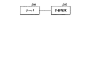
図16は、本発明の実施の形態1にかかる空気調和システムの機種選定システムの構成を示すブロック図である。空気調和システムの機種選定システムは、通信可能に接続されたサーバ301と外部端末302とを有する、空気調和システムの機種選定システムとして実現されてもよい。この場合、サーバ301が、演算部211と選定処理部212とを備える。また、外部端末302が、入力部230と提示部240とを備える。   FIG. 16 is a block diagram illustrating a configuration of a model selection system of the air conditioning system according to the first embodiment of the present invention. The air conditioning system model selection system may be realized as an air conditioning system model selection system having a server 301 and an external terminal 302 communicably connected. In this case, the server 301 includes a calculation unit 211 and a selection processing unit 212. Further, the external terminal 302 includes an input unit 230 and a presentation unit 240.

実施の形態2.
図17は、本発明の実施の形態2にかかる空気調和システムの概略構成図である。図18は、本発明の実施の形態2にかかる空気調和システムの風路の構成を示す模式図である。本実施の形態2にかかる空気調和システムは、循環風路5の経路数と、循環用送風機6の台数および配置とが異なる以外は、上述した実施の形態1にかかる空気調和システムと同様の構成である。したがって、本実施の形態2にかかる空気調和システムは、実施の形態1にかかる空気調和システムと同様の効果を有する。なお、実施の形態1にかかる空気調和システムと同様の構成の説明は省略する。
Embodiment 2 FIG.
FIG. 17 is a schematic configuration diagram of an air conditioning system according to Embodiment 2 of the present invention. FIG. 18 is a schematic diagram illustrating a configuration of an air passage of the air-conditioning system according to Embodiment 2 of the present invention. The air-conditioning system according to the second embodiment has the same configuration as the air-conditioning system according to the first embodiment except that the number of circulation air passages 5 and the number and arrangement of the circulation blowers 6 are different. It is. Therefore, the air conditioning system according to the second embodiment has the same effects as the air conditioning system according to the first embodiment. The description of the same configuration as that of the air-conditioning system according to Embodiment 1 is omitted.

本実施の形態2にかかる空気調和システムは、空気調和機が設置された居室2aと空気調和機が取り付けられていない居室2bとの間に、並列に配置された2本の給気風路5aである第1給気風路51aおよび第2給気風路52aが設けられている。第1給気風路51aの一端側は、空気調和機が設置された居室2aに接続されている。第1給気風路51aの他端側は、空気調和機が取り付けられていない居室21bに接続されている。第2給気風路52aの一端側は、空気調和機が設置された居室2aに接続されている。第2給気風路52aの他端側は、2つに分岐して、空気調和機が取り付けられていない居室22bおよび空気調和機が取り付けられていない居室23bに接続されている。第1給気風路51a中および第2給気風路52a中には、各々1台の循環用送風機6が設けられている。   The air conditioning system according to the second embodiment includes two air supply passages 5a arranged in parallel between a living room 2a in which an air conditioner is installed and a living room 2b in which no air conditioner is installed. A certain first air supply passage 51a and a certain second air supply passage 52a are provided. One end of the first air supply passage 51a is connected to the living room 2a in which the air conditioner is installed. The other end of the first air supply passage 51a is connected to the living room 21b to which the air conditioner is not attached. One end of the second air supply passage 52a is connected to the living room 2a in which the air conditioner is installed. The other end of the second supply air passage 52a is branched into two and connected to a living room 22b to which no air conditioner is attached and a living room 23b to which no air conditioner is attached. One circulation blower 6 is provided in each of the first air supply passage 51a and the second air supply passage 52a.

このように2本の給気風路5aである第1給気風路51a中および第2給気風路52a中に並列に複数の循環用送風機6を設ける場合、実施の形態1にかかる空気調和システムのように1台の循環用送風機6で送風を行う場合に比べて、空気調和機が取り付けられていない居室2bの部屋毎にきめ細かな循環風量Qを設定できるという効果を奏する。   In the case where a plurality of circulation blowers 6 are provided in parallel in the first supply air passage 51a and the second supply air passage 52a, which are the two supply air passages 5a, the air conditioning system according to the first embodiment will be described. As compared with the case where the air is blown by one circulation blower 6 as described above, there is an effect that the circulating air volume Q can be set finely for each room of the living room 2b to which the air conditioner is not attached.

本実施の形態2にかかる空気調和システムにおいては、第1給気風路51a中および第2給気風路52a中に並列に設けられた2台の循環用送風機6の設計風量の合計風量を循環風量Qとし、循環風量Qが上述した式(1)に示す条件を満たすように設定される。また、仮に、並列に配置された3本以上の複数の循環風路に3台以上の複数の循環用送風機6が並列に並ぶ場合は、複数の循環用送風機6の合計風量を循環風量Qとして考えて、複数の循環用送風機6の風量が制御される。   In the air conditioning system according to the second embodiment, the total air volume of the design air volumes of the two circulation blowers 6 provided in parallel in the first air supply passage 51a and in the second air supply passage 52a is determined by the circulation air volume. Q is set so that the circulating air volume Q satisfies the condition shown in the above equation (1). If three or more circulating blowers 6 are arranged in parallel in three or more circulating air passages arranged in parallel, the total air volume of the plurality of circulating blowers 6 is defined as a circulating air volume Q. Considering this, the air volume of the plurality of circulation blowers 6 is controlled.

実施の形態3.
図19は、本発明の実施の形態3にかかる空気調和システムの概略構成図である。図20は、本発明の実施の形態3にかかる空気調和システムの風路の構成を示す模式図である。本実施の形態3にかかる空気調和システムは、循環用送風機6の台数および配置が異なる以外は、上述した実施の形態1にかかる空気調和システムと同様の構成である。したがって、本実施の形態3にかかる空気調和システムは、実施の形態1にかかる空気調和システムと同様の効果を有する。なお、実施の形態1にかかる空気調和システムと同様の構成の説明は省略する。
Embodiment 3 FIG.
FIG. 19 is a schematic configuration diagram of an air-conditioning system according to Embodiment 3 of the present invention. FIG. 20 is a schematic diagram illustrating a configuration of an air path of the air-conditioning system according to Embodiment 3 of the present invention. The air conditioning system according to the third embodiment has the same configuration as that of the air conditioning system according to the first embodiment except that the number and arrangement of the circulation blowers 6 are different. Therefore, the air conditioning system according to the third embodiment has the same effects as the air conditioning system according to the first embodiment. The description of the same configuration as that of the air-conditioning system according to Embodiment 1 is omitted.

本実施の形態3にかかる空気調和システムは、給気風路5a中および環気風路5b中に循環用送風機6が1台ずつ設けられている。このように循環風路5中に直列で並ぶ複数の循環用送風機6を設ける場合には、実施の形態1にかかる空気調和システムのように1台の循環用送風機6で送風を行う場合に比べて、建物1の気密性および居室2の各部屋の通気性によらず、空気調和機が設置された居室2aと空気調和機が取り付けられていない居室2bとの間で確実に空気を循環させることができるという効果を奏する。   In the air conditioning system according to the third embodiment, one circulation blower 6 is provided in each of the supply air passage 5a and the ring air passage 5b. In the case where a plurality of circulation blowers 6 are provided in series in the circulation air passage 5 in this manner, compared with the case where air is blown by one circulation blower 6 as in the air conditioning system according to the first embodiment. Thus, regardless of the airtightness of the building 1 and the air permeability of each room of the living room 2, the air is reliably circulated between the living room 2a where the air conditioner is installed and the living room 2b where the air conditioner is not installed. It has the effect of being able to do so.

なお、本実施の形態3にかかる空気調和システムにおいては、環気風路5b中の循環用送風機6があれば空気調和機が設置された居室2aと空気調和機が取り付けられていない居室2bとの間で空気を循環させることができるので、給気風路5a中の循環用送風機6は必ずしも必要ではない。ただし、給気風路5a中の循環用送風機6を取り除く場合には、建物1の気密性を十分高くする必要がある。   In the air conditioning system according to the third embodiment, if there is a circulating blower 6 in the airflow path 5b, the room 2a in which the air conditioner is installed and the room 2b in which the air conditioner is not installed. Since the air can be circulated between them, the circulation blower 6 in the supply air passage 5a is not always necessary. However, when removing the circulation blower 6 in the supply air passage 5a, it is necessary to sufficiently increase the airtightness of the building 1.

本実施の形態3にかかる空気調和システムにおいては、循環風路5に対して直列に設けられた2台の循環用送風機6の設計風量のうち、いずれか風量の小さい方の循環用送風機6の風量を循環風量Qとして、式(1)を満たすように設定される。仮に3台以上の循環用送風機6が直列に並ぶ場合は、それら複数の循環用送風機6の設計風量のうち、最も小さい風量の循環用送風機6の風量を循環風量Qとして考えて、複数の循環用送風機6の風量が制御される。   In the air-conditioning system according to Embodiment 3, of the design airflows of the two circulation blowers 6 provided in series with the circulation airflow path 5, one of the design airflows of the circulation blower 6 having the smaller airflow is used. The air volume is set as the circulation air volume Q so as to satisfy Expression (1). If three or more circulating blowers 6 are arranged in series, a plurality of circulating blowers 6 are considered as the circulating airflow Q, and the circulating blower 6 having the smallest airflow among the design airflows of the plurality of circulating blowers 6 is considered. The air volume of the blower 6 is controlled.

実施の形態4.
図21は、本発明の実施の形態4にかかる空気調和システムの概略構成図である。図22は、本発明の実施の形態4にかかる空気調和システムの風路の構成を示す模式図である。本実施の形態4にかかる空気調和システムの構成は、循環風路5の経路数と、循環用送風機6の台数および配置が異なること以外は、上述した実施の形態1にかかる空気調和システムと同様の構成である。したがって、本実施の形態4にかかる空気調和システムは、実施の形態1にかかる空気調和システムと同様の効果を有する。なお、実施の形態1にかかる空気調和システムと同様の構成の説明は省略する。
Embodiment 4 FIG.
FIG. 21 is a schematic configuration diagram of an air conditioning system according to Embodiment 4 of the present invention. FIG. 22 is a schematic diagram illustrating a configuration of an air passage of the air-conditioning system according to Embodiment 4 of the present invention. The configuration of the air-conditioning system according to Embodiment 4 is the same as that of the air-conditioning system according to Embodiment 1 except that the number of circulation air passages 5 and the number and arrangement of the circulation blowers 6 are different. It is a structure of. Therefore, the air-conditioning system according to Embodiment 4 has the same effects as the air-conditioning system according to Embodiment 1. The description of the same configuration as that of the air-conditioning system according to Embodiment 1 is omitted.

本実施の形態4にかかる空気調和システムは、空気調和機が取り付けられていない居室2bごとに、給気風路5a、環気風路5bおよび循環用送風機6が設けられている。   The air-conditioning system according to Embodiment 4 is provided with a supply air passage 5a, a ring air passage 5b, and a circulation blower 6 for each living room 2b to which no air conditioner is attached.

本実施の形態4にかかる空気調和システムは、空気調和機が設置された居室2aと空気調和機が取り付けられていない居室2bとの間に、並列に配置された3本の給気風路5aである第1給気風路51a、第2給気風路52aおよび第3給気風路53aが設けられている。第1給気風路51aの一端側は、空気調和機が設置された居室2aに接続されている。第1給気風路51aの他端側は、空気調和機が取り付けられていない居室21bに接続されている。第2給気風路52aの一端側は、空気調和機が設置された居室2aに接続されている。第2給気風路52aの他端側は、空気調和機が取り付けられていない居室22bに接続されている。第3給気風路53aの一端側は、空気調和機が設置された居室2aに接続されている。第3給気風路53aの他端側は、空気調和機が取り付けられていない居室23bに接続されている。第1給気風路51a中、第2給気風路52a中、および第3給気風路53a中は、各々1台の循環用送風機6が設けられている。   The air-conditioning system according to Embodiment 4 includes three supply air passages 5a arranged in parallel between a living room 2a in which an air conditioner is installed and a living room 2b in which no air conditioner is installed. A certain first air supply passage 51a, a second air supply air passage 52a, and a third air supply air passage 53a are provided. One end of the first air supply passage 51a is connected to the living room 2a in which the air conditioner is installed. The other end of the first air supply passage 51a is connected to the living room 21b to which the air conditioner is not attached. One end of the second air supply passage 52a is connected to the living room 2a in which the air conditioner is installed. The other end of the second air supply passage 52a is connected to the living room 22b to which the air conditioner is not attached. One end of the third air supply passage 53a is connected to the living room 2a in which the air conditioner is installed. The other end of the third air supply passage 53a is connected to the living room 23b to which the air conditioner is not attached. One circulation blower 6 is provided in each of the first air supply passage 51a, the second air supply passage 52a, and the third air supply passage 53a.

本実施の形態4にかかる空気調和システムは、空気調和機が設置された居室2aと空気調和機が取り付けられていない居室2bとの間に、並列に配置された3本の環気風路5bである第1環気風路51b、第2環気風路52bおよび第3環気風路53bが設けられている。第1環気風路51bの一端側は、空気調和機が設置された居室2aに接続されている。第1環気風路51bの他端側は、空気調和機が取り付けられていない居室21bに接続されている。第2環気風路52bの一端側は、空気調和機が設置された居室2aに接続されている。第2環気風路52bの他端側は、空気調和機が取り付けられていない居室22bに接続されている。第3環気風路53bの一端側は、空気調和機が設置された居室2aに接続されている。第3環気風路53bの他端側は、空気調和機が取り付けられていない居室23bに接続されている。   The air-conditioning system according to Embodiment 4 includes three ring air passages 5b arranged in parallel between a living room 2a in which an air conditioner is installed and a living room 2b in which no air conditioner is installed. A certain first air path 51b, a second air path 52b, and a third air path 53b are provided. One end side of the first ring air passage 51b is connected to the living room 2a in which the air conditioner is installed. The other end of the first ring air passage 51b is connected to the living room 21b to which the air conditioner is not attached. One end of the second annular air passage 52b is connected to the living room 2a in which the air conditioner is installed. The other end of the second annular air passage 52b is connected to the living room 22b to which the air conditioner is not attached. One end of the third ring air passage 53b is connected to the living room 2a in which the air conditioner is installed. The other end of the third annular air passage 53b is connected to the living room 23b to which the air conditioner is not attached.

このように空気調和機が取り付けられていない居室2bごとに、給気風路5a、環気風路5bおよび循環用送風機6を設ける場合には、実施の形態2にかかる空気調和システムに比べて、空気調和機が取り付けられていない居室2bの部屋毎にきめ細かな循環風量を設定できるという効果を奏する。   When the supply air passage 5a, the ring air passage 5b, and the circulation blower 6 are provided for each of the living rooms 2b to which the air conditioner is not attached as described above, compared to the air conditioning system according to the second embodiment, There is an effect that a fine circulating air volume can be set for each room of the living room 2b to which no harmony device is attached.

本実施の形態4にかかる空気調和システムにおいては、循環風路5である給気風路5aに対して並列に設けられた3台の循環用送風機6の設計風量の合計風量を循環風量Qとする。   In the air-conditioning system according to Embodiment 4, the total air volume of the design air volumes of the three circulating blowers 6 provided in parallel with the supply air channel 5a, which is the circulating air channel 5, is defined as the circulating air volume Q. .

実施の形態5.
図23は、本発明の実施の形態5にかかる空気調和システムの風路の構成を示す模式図である。本実施の形態5にかかる空気調和システムの構成は、空気調和機が取り付けられていない居室2bの数量および循環風路5の経路が異なること以外は、基本的に上述した実施の形態1にかかる空気調和システムと同様の構成である。したがって、本実施の形態5にかかる空気調和システムは、実施の形態1にかかる空気調和システムと同様の効果を有する。なお、実施の形態1にかかる空気調和システムと同様の構成の説明は省略する。
Embodiment 5 FIG.
FIG. 23 is a schematic diagram illustrating a configuration of an air passage of the air-conditioning system according to Embodiment 5 of the present invention. The configuration of the air-conditioning system according to the fifth embodiment is basically the same as that of the first embodiment except that the number of living rooms 2b to which the air conditioner is not attached and the path of the circulation air passage 5 are different. It has the same configuration as the air conditioning system. Therefore, the air-conditioning system according to Embodiment 5 has the same effects as the air-conditioning system according to Embodiment 1. The description of the same configuration as that of the air-conditioning system according to Embodiment 1 is omitted.

本実施の形態5にかかる空気調和システムは、上述した実施の形態1にかかる空気調和システムにおいて、空気調和機が取り付けられていない居室23bが設けられていない構成を有する。すなわち、本実施の形態5にかかる空気調和システムは、空気調和機が取り付けられていない居室2bとして、空気調和機が取り付けられていない居室21bおよび空気調和機が取り付けられていない居室22bの2つの居室が2階に設けられている。   The air conditioning system according to the fifth embodiment has a configuration in which the living room 23b to which the air conditioner is not attached is not provided in the air conditioning system according to the first embodiment. That is, the air-conditioning system according to Embodiment 5 includes, as the living room 2b to which no air conditioner is attached, two living rooms 21b to which no air conditioner is attached and a living room 22b to which no air conditioner is attached. The living room is located on the second floor.

給気風路5aの一端側は、空気調和機が設置された居室2aに接続されている。給気風路5aの他端側は、2つに分岐して、空気調和機が取り付けられていない居室21bおよび空気調和機が取り付けられていない居室22bに接続されている。環気風路5bの一端側は、空気調和機が設置された居室2aに接続されている。環気風路5bの他端側は、2つに分岐して、空気調和機が取り付けられていない居室21bおよび空気調和機が取り付けられていない居室22bに接続されている。   One end of the supply air passage 5a is connected to the living room 2a in which the air conditioner is installed. The other end of the supply air passage 5a is branched into two and connected to a living room 21b to which no air conditioner is attached and a living room 22b to which no air conditioner is attached. One end of the airflow path 5b is connected to the living room 2a in which the air conditioner is installed. The other end of the airflow path 5b is branched into two and connected to a living room 21b to which no air conditioner is attached and a living room 22b to which no air conditioner is attached.

一方、不図示の循環用送風機6は、空気調和機が設置された居室2aと空気調和機が取り付けられていない居室2bの間を循環させる空気流を発生させられればよく、給気風路5a中の任意の場所または環気風路5b中の任意の場所に設けられればよい。   On the other hand, the circulation blower 6 (not shown) only needs to be able to generate an air flow that circulates between the living room 2a where the air conditioner is installed and the living room 2b where the air conditioner is not installed. May be provided at any place of the air path or at any place in the airflow path 5b.

このように構成された本実施の形態5にかかる空気調和システムは、給気風路5aの他端側が2つに分岐されて空気調和機が取り付けられていない居室21bおよび空気調和機が取り付けられていない居室22bに接続されているため、循環風路5のダクト等の使用量を削減することができる。また、本実施の形態5にかかる空気調和システムは、環気風路5bの他端側が2つに分岐されて空気調和機が取り付けられていない居室21bおよび空気調和機が取り付けられていない居室22bに接続されているため、循環風路5のダクト等の使用量を削減することができる。したがって、本実施の形態5にかかる空気調和システムは、安価な空気調和システムを提供できるという効果を奏する。   The air-conditioning system according to Embodiment 5 configured as described above has the other end of the supply air passage 5a branched into two, and the living room 21b to which no air conditioner is attached and the air conditioner are attached. Since it is connected to the unoccupied living room 22b, it is possible to reduce the amount of use of the duct and the like of the circulation air passage 5. In the air conditioning system according to Embodiment 5, the other end of the airflow path 5b is branched into two to provide a living room 21b without an air conditioner and a living room 22b without an air conditioner. Since they are connected, it is possible to reduce the amount of use of the duct and the like of the circulation air passage 5. Therefore, the air-conditioning system according to Embodiment 5 has an effect that an inexpensive air-conditioning system can be provided.

実施の形態6.
図24は、本発明の実施の形態6にかかる空気調和システムの風路の構成を示す模式図である。本実施の形態6にかかる空気調和システムの構成は、空気調和機が取り付けられていない居室2bの数量および循環風路5の経路が異なること以外は、基本的に上述した実施の形態2にかかる空気調和システムと同様の構成である。したがって、本実施の形態6にかかる空気調和システムは、実施の形態1,2にかかる空気調和システムと同様の効果を有する。なお、実施の形態1,2にかかる空気調和システムと同様の構成の説明は省略する。
Embodiment 6 FIG.
FIG. 24 is a schematic diagram illustrating a configuration of an air path of the air-conditioning system according to Embodiment 6 of the present invention. The configuration of the air conditioning system according to the sixth embodiment is basically the same as that of the second embodiment described above, except that the number of living rooms 2b to which no air conditioner is attached and the path of the circulation air passage 5 are different. It has the same configuration as the air conditioning system. Therefore, the air-conditioning system according to Embodiment 6 has the same effects as the air-conditioning systems according to Embodiments 1 and 2. The description of the same configuration as the air-conditioning system according to Embodiments 1 and 2 is omitted.

本実施の形態6にかかる空気調和システムは、上述した実施の形態2にかかる空気調和システムにおいて、空気調和機が取り付けられていない居室23bが設けられていない構成を有する。すなわち、本実施の形態6にかかる空気調和システムは、空気調和機が取り付けられていない居室2bとして、空気調和機が取り付けられていない居室21bおよび空気調和機が取り付けられていない居室22bの2つの居室が2階に設けられている。   The air conditioning system according to Embodiment 6 has a configuration in which the living room 23b to which the air conditioner is not attached is not provided in the air conditioning system according to Embodiment 2 described above. That is, the air-conditioning system according to Embodiment 6 includes, as the living room 2b to which no air conditioner is attached, two living rooms 21b to which no air conditioner is attached and a living room 22b to which no air conditioner is attached. The living room is located on the second floor.

第1給気風路51aの一端側は、空気調和機が設置された居室2aに接続されている。第1給気風路51aの他端側は、空気調和機が取り付けられていない居室21bに接続されている。第2給気風路52aの一端側は、空気調和機が設置された居室2aに接続されている。第2給気風路52aの他端側は、空気調和機が取り付けられていない居室22bに接続されている。したがって、本実施の形態6にかかる空気調和システムは、給気風路5aを、第2の居室毎に有している。   One end of the first air supply passage 51a is connected to the living room 2a in which the air conditioner is installed. The other end of the first air supply passage 51a is connected to the living room 21b to which the air conditioner is not attached. One end of the second air supply passage 52a is connected to the living room 2a in which the air conditioner is installed. The other end of the second air supply passage 52a is connected to the living room 22b to which the air conditioner is not attached. Therefore, the air-conditioning system according to Embodiment 6 includes the supply air passage 5a for each second living room.

環気風路5bの一端側は、空気調和機が設置された居室2aに接続されている。環気風路5bの他端側は、2つに分岐して、空気調和機が取り付けられていない居室21bおよび空気調和機が取り付けられていない居室22bに接続されている。したがって、本実施の形態6にかかる空気調和システムでは、環気風路5は、一端側が第1の居室に接続されるとともに他端側が複数の第2の居室に接続されている。   One end of the airflow path 5b is connected to the living room 2a in which the air conditioner is installed. The other end of the airflow path 5b is branched into two and connected to a living room 21b to which no air conditioner is attached and a living room 22b to which no air conditioner is attached. Therefore, in the air conditioning system according to the sixth embodiment, the ring air passage 5 has one end connected to the first living room and the other end connected to the plurality of second living rooms.

第1給気風路51a中および第2給気風路52a中には、各々1台の循環用送風機6が設けられている。循環用送風機6は、空気調和機が設置された居室2aと空気調和機が取り付けられていない居室2bの間を循環させる空気流を発生させられればよく、第1給気風路51a中の任意の場所および第2給気風路52a中の任意の場所に設けられればよい。   One circulation blower 6 is provided in each of the first air supply passage 51a and the second air supply passage 52a. The circulation blower 6 only needs to be able to generate an airflow that circulates between the living room 2a in which the air conditioner is installed and the living room 2b in which the air conditioner is not installed, and any air in the first air supply passage 51a may be generated. It may be provided at any location in the location and the second air supply passage 52a.

このように構成された本実施の形態6にかかる空気調和システムは、2本の給気風路5aである第1給気風路51a中および第2給気風路52a中に並列に複数の循環用送風機6を設けるため、空気調和機が設置されていない居室2bに供給する風量を居室ごとに独立に変更することでき、空気調和機が取り付けられていない居室2bの部屋毎にきめ細かな循環風量Qを設定できる。したがって、本実施の形態6にかかる空気調和システムは、、実施の形態5にかかる空気調和システムに比べて、循環風量Qの風量の調整に長けるという効果を奏する。   The air conditioning system according to the sixth embodiment thus configured has a plurality of circulation blowers in parallel in the first air supply passage 51a and the second air supply passage 52a, which are two air supply passages 5a. 6, the amount of air supplied to the living room 2b in which the air conditioner is not installed can be independently changed for each living room, and the fine circulating air flow Q can be changed for each room in the living room 2b in which the air conditioner is not installed. Can be set. Therefore, the air-conditioning system according to the sixth embodiment has an effect that the air-conditioning system according to the fifth embodiment is longer in adjusting the air volume of the circulating air volume Q than the air-conditioning system according to the fifth embodiment.

実施の形態7.
図25は、本発明の実施の形態7にかかる空気調和システムの風路の構成を示す模式図である。本実施の形態7にかかる空気調和システムの構成は、空気調和機が取り付けられていない居室2bの数量および循環風路5の経路が異なること以外は、基本的に上述した実施の形態1にかかる空気調和システムと同様の構成である。したがって、本実施の形態7にかかる空気調和システムは、実施の形態1にかかる空気調和システムと同様の効果を有する。なお、実施の形態1にかかる空気調和システムと同様の構成の説明は省略する。
Embodiment 7 FIG.
FIG. 25 is a schematic diagram illustrating a configuration of an air passage of the air-conditioning system according to Embodiment 7 of the present invention. The configuration of the air conditioning system according to the seventh embodiment is basically the same as that of the first embodiment except that the number of living rooms 2b to which no air conditioner is attached and the path of the circulation air passage 5 are different. It has the same configuration as the air conditioning system. Therefore, the air-conditioning system according to Embodiment 7 has the same effect as the air-conditioning system according to Embodiment 1. The description of the same configuration as that of the air-conditioning system according to Embodiment 1 is omitted.

本実施の形態7にかかる空気調和システムは、上述した実施の形態1にかかる空気調和システムにおいて、空気調和機が取り付けられていない居室23bが設けられていない構成を有する。すなわち、本実施の形態7にかかる空気調和システムは、空気調和機が取り付けられていない居室2bとして、空気調和機が取り付けられていない居室21bおよび空気調和機が取り付けられていない居室22bの2つの居室が2階に設けられている。   The air conditioning system according to Embodiment 7 has a configuration in which the living room 23b to which the air conditioner is not attached is provided in the air conditioning system according to Embodiment 1 described above. That is, the air-conditioning system according to Embodiment 7 includes, as the living room 2b to which no air conditioner is attached, two living rooms 21b to which no air conditioner is attached and a living room 22b to which no air conditioner is attached. The living room is located on the second floor.

給気風路5aの一端側は、空気調和機が設置された居室2aに接続されている。給気風路5aの他端側は、2つに分岐して、空気調和機が取り付けられていない居室21bおよび空気調和機が取り付けられていない居室22bに接続されている。すなわち、本実施の形態7にかかる空気調和システムでは、給気風路5aは、一端側が第1の居室に接続されるとともに他端側が複数の第2の居室に接続されている。   One end of the supply air passage 5a is connected to the living room 2a in which the air conditioner is installed. The other end of the supply air passage 5a is branched into two and connected to a living room 21b to which no air conditioner is attached and a living room 22b to which no air conditioner is attached. That is, in the air conditioning system according to the seventh embodiment, the supply air passage 5a has one end connected to the first living room and the other end connected to the plurality of second living rooms.

本実施の形態7にかかる空気調和システムは、空気調和機が設置された居室2aと空気調和機が取り付けられていない居室2bとの間に、並列に配置された2本の環気風路5bである第1環気風路51bおよび第2環気風路52bが設けられている。第1環気風路51bの一端側は、空気調和機が設置された居室2aに接続されている。第1環気風路51bの他端側は、空気調和機が取り付けられていない居室21bに接続されている。第2環気風路52bの一端側は、空気調和機が設置された居室2aに接続されている。第2環気風路52bの他端側は、空気調和機が取り付けられていない居室22bに接続されている。したがって、本実施の形態7にかかる空気調和システムは、環気風路5bを、第2の居室毎に有している。   The air-conditioning system according to Embodiment 7 includes two ring air passages 5b arranged in parallel between a living room 2a in which an air conditioner is installed and a living room 2b in which no air conditioner is installed. A certain first annular air passage 51b and a second annular air passage 52b are provided. One end side of the first ring air passage 51b is connected to the living room 2a in which the air conditioner is installed. The other end of the first ring air passage 51b is connected to the living room 21b to which the air conditioner is not attached. One end of the second annular air passage 52b is connected to the living room 2a in which the air conditioner is installed. The other end of the second annular air passage 52b is connected to the living room 22b to which the air conditioner is not attached. Therefore, the air-conditioning system according to Embodiment 7 has a ring air passage 5b for each second living room.

一方、不図示の循環用送風機6は、空気調和機が設置された居室2aと空気調和機が取り付けられていない居室2bの間を循環させる空気流を発生させられればよく、給気風路5a、第1環気風路51bおよび第2環気風路52bのうち任意の場所に設けられればよい。   On the other hand, the circulation blower 6 (not shown) only needs to generate an airflow that circulates between the living room 2a where the air conditioner is installed and the living room 2b where the air conditioner is not installed. What is necessary is just to provide in the arbitrary places among the 1st ring air path 51b and the 2nd ring air path 52b.

このように構成された本実施の形態7にかかる空気調和システムは、給気風路5aの他端側が2つに分岐されて空気調和機が取り付けられていない居室21bおよび空気調和機が取り付けられていない居室22bに接続されているため、循環風路5のダクト等の使用量を削減することができ、安価な空気調和システムを提供できるという効果を奏する。   The air-conditioning system according to Embodiment 7 configured as above has the other end of the supply air passage 5a branched into two, and the living room 21b without the air-conditioner and the air-conditioner are mounted. Since it is connected to the unoccupied living room 22b, the amount of use of the duct and the like of the circulation air passage 5 can be reduced, and an effect that an inexpensive air conditioning system can be provided is achieved.

また、本実施の形態7にかかる空気調和システムは、空気調和機が取り付けられていない居室2bごとに環気風路5bを備えるため、空気調和機が取り付けられていない居室21bと空気調和機が取り付けられていない居室22bとの距離が長くなる場合でも、空気調和機が取り付けられていない居室2bの空気を、環気風路5bを介して空気調和機が設置された居室2aに確実に戻すことができる、という効果を奏する。   In addition, since the air conditioning system according to Embodiment 7 includes a ring air passage 5b for each of the living rooms 2b to which no air conditioner is attached, the air conditioner is attached to the living room 21b to which no air conditioner is attached. Even when the distance to the unoccupied room 22b is long, it is possible to reliably return the air in the room 2b without the air conditioner to the room 2a where the air conditioner is installed via the airflow path 5b. It has the effect of being able to.

実施の形態8.
図26は、本発明の実施の形態8にかかる空気調和システムの風路の構成を示す模式図である。本実施の形態8にかかる空気調和システムの構成は、空気調和機が取り付けられていない居室2bの数量および循環風路5の経路が異なること以外は、基本的に上述した実施の形態4にかかる空気調和システムと同様の構成である。したがって、本実施の形態8にかかる空気調和システムは、実施の形態4にかかる空気調和システムと同様の効果を有する。なお、実施の形態4にかかる空気調和システムと同様の構成の説明は省略する。
Embodiment 8 FIG.
FIG. 26 is a schematic diagram illustrating a configuration of an air passage of the air-conditioning system according to Embodiment 8 of the present invention. The configuration of the air conditioning system according to the eighth embodiment is basically the same as that of the fourth embodiment except that the number of living rooms 2b to which the air conditioner is not attached and the path of the circulation air passage 5 are different. It has the same configuration as the air conditioning system. Therefore, the air-conditioning system according to Embodiment 8 has the same effects as the air-conditioning system according to Embodiment 4. The description of the same configuration as that of the air-conditioning system according to Embodiment 4 is omitted.

本実施の形態8にかかる空気調和システムは、上述した実施の形態4にかかる空気調和システムにおいて、空気調和機が取り付けられていない居室23bが設けられていない構成を有する。すなわち、本実施の形態8にかかる空気調和システムは、空気調和機が取り付けられていない居室2bとして、空気調和機が取り付けられていない居室21bおよび空気調和機が取り付けられていない居室22bの2つの居室が2階に設けられている。   The air conditioning system according to the eighth embodiment has a configuration in which the living room 23b to which the air conditioner is not attached is not provided in the air conditioning system according to the fourth embodiment. That is, the air-conditioning system according to Embodiment 8 includes, as the living room 2b without the air conditioner, the living room 21b without the air conditioner and the living room 22b without the air conditioner. The living room is located on the second floor.

本実施の形態8にかかる空気調和システムは、空気調和機が設置された居室2aと空気調和機が取り付けられていない居室2bとの間に、並列に配置された2本の給気風路5aである第1給気風路51aおよび第2給気風路52aが設けられている。また、本実施の形態8にかかる空気調和システムは、空気調和機が設置された居室2aと空気調和機が取り付けられていない居室2bとの間に、並列に配置された2本の環気風路5bである第1環気風路51bおよび第2環気風路52bが設けられている。したがって、本実施の形態8にかかる空気調和システムは、給気風路5aと環気風路5bとを、第2の居室毎に有している。   The air-conditioning system according to Embodiment 8 includes two supply air passages 5a arranged in parallel between a living room 2a in which an air conditioner is installed and a living room 2b in which no air conditioner is installed. A certain first air supply passage 51a and a certain second air supply passage 52a are provided. The air conditioning system according to the eighth embodiment includes two ring air passages arranged in parallel between a living room 2a in which an air conditioner is installed and a living room 2b in which no air conditioner is installed. 5b, a first ring air passage 51b and a second ring air passage 52b are provided. Therefore, the air conditioning system according to Embodiment 8 includes the supply air passage 5a and the ring air passage 5b for each second living room.

一方、不図示の循環用送風機6は、空気調和機が設置された居室2aと空気調和機が取り付けられていない居室2bの間を循環させる空気流を発生させられればよく、第1給気風路51aおよび第1環気風路51bのうちの任意の場所と、第2給気風路52aおよび第2環気風路52bのうちの任意の場所に設けられればよい。   On the other hand, the circulation blower 6 (not shown) only needs to generate an airflow that circulates between the living room 2a in which the air conditioner is installed and the living room 2b in which the air conditioner is not installed. What is necessary is just to provide in arbitrary places of 51a and the 1st annular air path 51b, and arbitrary places of the 2nd supply air path 52a and the 2nd annular air path 52b.

このように構成された本実施の形態8にかかる空気調和システムは、空気調和機が設置されていない居室2bに供給する風量を空気調和機が設置されていない居室2bごとに独立に変更することでき、空気調和機が取り付けられていない居室2bの部屋毎にきめ細かな循環風量Qを設定できる。   The air-conditioning system according to Embodiment 8 configured as described above independently changes the amount of air supplied to the room 2b where no air conditioner is installed for each room 2b where no air conditioner is installed. It is possible to set a fine circulating air volume Q for each room of the living room 2b to which the air conditioner is not attached.

また、本実施の形態8にかかる空気調和システムは、空気調和機が取り付けられていない居室2bごとに環気風路5bを備えるため、空気調和機が取り付けられていない居室21bと空気調和機が取り付けられていない居室22bとの距離が長くなる場合でも、空気調和機が取り付けられていない居室2bの空気を、環気風路5bを介して空気調和機が設置された居室2aに確実に戻すことができる、という効果を奏する。   In addition, the air-conditioning system according to Embodiment 8 includes the air circulation path 5b for each of the living rooms 2b to which the air conditioner is not attached, so that the room 21b to which the air conditioner is not attached and the air conditioner are attached. Even when the distance to the unoccupied room 22b is long, it is possible to reliably return the air in the room 2b without the air conditioner to the room 2a where the air conditioner is installed via the airflow path 5b. It has the effect of being able to.

実施の形態9.
図27は、本発明の実施の形態9にかかる空気調和システムの風路の構成を示す模式図である。本実施の形態9にかかる空気調和システムの構成は、空気調和機が取り付けられていない居室2bの数量および循環風路5の経路が異なること以外は、基本的に上述した実施の形態1にかかる空気調和システムと同様の構成である。したがって、本実施の形態9にかかる空気調和システムは、実施の形態1にかかる空気調和システムと同様の効果を有する。なお、実施の形態1にかかる空気調和システムと同様の構成の説明は省略する。
Embodiment 9 FIG.
FIG. 27 is a schematic diagram illustrating a configuration of an air passage of the air-conditioning system according to Embodiment 9 of the present invention. The configuration of the air-conditioning system according to the ninth embodiment is basically the same as that of the first embodiment except that the number of living rooms 2b to which the air conditioner is not attached and the path of the circulation air passage 5 are different. It has the same configuration as the air conditioning system. Therefore, the air-conditioning system according to Embodiment 9 has the same effects as the air-conditioning system according to Embodiment 1. The description of the same configuration as that of the air-conditioning system according to Embodiment 1 is omitted.

本実施の形態9にかかる空気調和システムは、上述した実施の形態1にかかる空気調和システムにおいて、空気調和機が取り付けられていない居室23bが設けられていない構成を有する。すなわち、本実施の形態9にかかる空気調和システムは、空気調和機が取り付けられていない居室2bとして、空気調和機が取り付けられていない居室21bおよび空気調和機が取り付けられていない居室22bの2つの居室が2階に設けられている。   The air conditioning system according to the ninth embodiment has a configuration in which the living room 23b to which the air conditioner is not attached is not provided in the air conditioning system according to the first embodiment. That is, the air-conditioning system according to Embodiment 9 includes, as the living room 2b to which no air conditioner is attached, two living rooms 21b to which no air conditioner is attached and a living room 22b to which no air conditioner is attached. The living room is located on the second floor.

給気風路5aの一端側は、空気調和機が設置された居室2aに接続されている。給気風路5aの他端側は、空気調和機が取り付けられていない居室21bに接続されている。第1環気風路51bの一端側は、空気調和機が取り付けられていない居室21bに接続されている。第1環気風路51bの他端側は、空気調和機が取り付けられていない居室22bに接続されている。第2環気風路52bの一端側は、空気調和機が取り付けられていない居室22bに接続されている。第2環気風路52bの他端側は、空気調和機が設置された居室2aに接続されている。   One end of the supply air passage 5a is connected to the living room 2a in which the air conditioner is installed. The other end of the supply air passage 5a is connected to a living room 21b to which no air conditioner is attached. One end side of the first ring air passage 51b is connected to the living room 21b to which the air conditioner is not attached. The other end of the first ring air passage 51b is connected to the living room 22b to which the air conditioner is not attached. One end side of the second annular air passage 52b is connected to the living room 22b to which the air conditioner is not attached. The other end of the second ring air passage 52b is connected to the living room 2a in which the air conditioner is installed.

第1環気風路51bは、第2の居室である空気調和機が取り付けられていない居室21bと、他の第2の居室である空気調和機が取り付けられていない居室22bとを接続して、第2の居室の空気を他の第2の居室に導くための風路である。そして、本実施の形態9にかかる空気調和システムでは、給気風路5aは、一端側が第1の居室に接続されるとともに他端側が第2の居室に接続されている。また、環気風路5は、一端側が第1の居室に接続されるとともに他端側が他の第2の居室に接続されている。   The first ring air passage 51b connects the second room, the room 21b, to which the air conditioner is not attached, and the other second room, the room 22b, to which the air conditioner is not attached, This is an air passage for guiding the air in the second room to another second room. In the air conditioning system according to the ninth embodiment, the supply air passage 5a has one end connected to the first living room and the other end connected to the second living room. Further, the ring air passage 5 has one end connected to the first living room and the other end connected to the other second living room.

不図示の循環用送風機6は、空気調和機が設置された居室2aと空気調和機が取り付けられていない居室2bの間を循環させる空気流を発生させられればよく、給気風路5a、第1環気風路51bおよび第2環気風路52bのうちの任意の場所に設けられればよい。   The circulation blower 6 (not shown) only needs to generate an airflow that circulates between the living room 2a where the air conditioner is installed and the living room 2b where the air conditioner is not installed. What is necessary is just to provide in the arbitrary location of the airflow path 51b and the 2nd airway 52b.

これにより、空気調和機が設置された居室2aの空気は、空気調和機が取り付けられていない居室21bに送られるとともに、空気調和機が取り付けられていない居室21bを介して空気調和機が取り付けられていない居室22bに送られる。また、空気調和機が取り付けられていない居室21bの空気が空気調和機が取り付けられていない居室22bに送られる。したがって、本実施の形態9にかかる空気調和システムは、空気調和機が設置された居室2aと、空気調和機が取り付けられていない居室21bと、空気調和機が取り付けられていない居室21bとの間で空気を循環させることができる。   Thereby, the air in the room 2a in which the air conditioner is installed is sent to the room 21b in which the air conditioner is not installed, and the air conditioner is installed through the room 21b in which the air conditioner is not installed. It is sent to the unoccupied room 22b. Further, the air in the room 21b to which the air conditioner is not attached is sent to the room 22b to which no air conditioner is attached. Therefore, the air-conditioning system according to Embodiment 9 includes the room 2a in which the air conditioner is installed, the room 21b in which the air conditioner is not installed, and the room 21b in which the air conditioner is not installed. Can circulate the air.

このように構成された本実施の形態9にかかる空気調和システムは、空気調和機が取り付けられていない居室21bおよび空気調和機が取り付けられていない居室22bに対して調和空気を循環させる給気風路5aが、空気調和機が取り付けられていない居室21bに接続する1本のみとされている。これにより、本実施の形態9にかかる空気調和システムは、循環風路5のダクト等の使用量を削減することができ、安価な空気調和システムを提供できるという効果を奏する。   The air conditioning system according to the ninth embodiment configured as described above has an air supply passage that circulates conditioned air to the living room 21b to which no air conditioner is attached and the living room 22b to which no air conditioner is attached. There is only one 5a connected to the living room 21b to which the air conditioner is not attached. Thus, the air-conditioning system according to the ninth embodiment has the effect of reducing the amount of use of the duct and the like of the circulating air passage 5 and providing an inexpensive air-conditioning system.

以上の実施の形態に示した構成は、本発明の内容の一例を示すものであり、別の公知の技術と組み合わせることも可能であるし、本発明の要旨を逸脱しない範囲で、構成の一部を省略、変更することも可能である。   The configurations described in the above embodiments are merely examples of the contents of the present invention, and can be combined with other known technologies, and can be combined with other known technologies without departing from the gist of the present invention. It is also possible to omit or change the part.

1 建物、2 居室、2a 空気調和機が設置された居室、2b,21b,22b,23b 空気調和機が取り付けられていない居室、3 非居室、4 空気調和機、4a 室内機、4b 室外機、4c 空気調和機操作端末、5 循環風路、5a 給気風路、5b 環気風路、6 循環用送風機、7 断熱部材、8a,8b 吸込口、9a,9b 吹出口、10 通気用開口、11 外壁、12 屋根、31 送風部、32 送風機制御部、33 送風機通信部、41 空気調和機制御部、42 室内機通信部、43 室内温度センサ、50 送風機操作端末、51a 第1給気風路、52a 第2給気風路、53a 第3給気風路、51b 第1環気風路、52b 第2環気風路、53b 第3環気風路、60 送風機操作端末、61 入力部、62 表示部、63 端末制御部、64 記憶部、65 端末通信部、101 プロセッサ、102 メモリ、200 空気調和システムの機種選定装置、210 制御部、211 演算部、212 選定処理部、220 記憶部、221 選定条件記憶部、222 空気調和機候補記憶部、223 循環用送風機候補記憶部、224 選定結果記憶部、230 入力部、240 提示部、250 通信部、261 CPU、262 RAM、263 ROM、264 外部記憶装置、265 通信インタフェース、266 入力デバイス、267 ディスプレイ、268 バス、301 サーバ、302 外部端末、Q 循環用送風機の風量、UA 外皮平均熱貫流率、V 循環風路に接続される部屋の合計の室容積、ηAC 冷房期の平均日射熱取得率、ηAH 暖房機の平均日射熱取得率。   1 building, 2 living room, 2a living room with air conditioner installed, 2b, 21b, 22b, 23b living room without air conditioner installed, 3 non-living room, 4 air conditioner, 4a indoor unit, 4b outdoor unit, 4c Air conditioner operation terminal, 5 circulation air path, 5a supply air path, 5b ring air path, 6 circulation blower, 7 heat insulating member, 8a, 8b inlet, 9a, 9b outlet, 10 ventilation opening, 11 outer wall , 12 roof, 31 blower section, 32 blower control section, 33 blower communication section, 41 air conditioner control section, 42 indoor unit communication section, 43 indoor temperature sensor, 50 blower operation terminal, 51a first air supply path, 52a 2 supply air path, 53a third supply air path, 51b first ring air path, 52b second ring air path, 53b third ring air path, 60 fan operation terminal, 61 input section, 62 display section, 6 3 terminal control unit, 64 storage unit, 65 terminal communication unit, 101 processor, 102 memory, 200 air conditioner system model selection device, 210 control unit, 211 calculation unit, 212 selection processing unit, 220 storage unit, 221 selection condition storage Unit, 222 air conditioner candidate storage unit, 223 circulation blower candidate storage unit, 224 selection result storage unit, 230 input unit, 240 presentation unit, 250 communication unit, 261 CPU, 262 RAM, 263 ROM, 264 external storage device, 265 communication interface, 266 input device, 267 display, 268 bus, 301 server, 302 external terminal, air volume of Q circulation blower, UA average heat transfer coefficient, V total room volume of room connected to circulation air channel, ηAC Average solar heat gain during cooling period, ηAH Average day of heater Heat gain coefficient.

Claims (19)

建物における第1の居室に設置されて前記第1の居室の空気調和を行う空気調和機と、
前記建物内における第2の居室と前記第1の居室との間で前記第1の居室内の空気と前記第2の居室内の空気とを循環させるための循環風路と、
前記循環風路を流れる空気流を発生させる循環用送風機と、
を備え、
前記空気調和機により空気調和された前記第1の居室内の空気を前記循環風路を通して前記第2の居室に送り、前記循環風路を通して前記第2の居室内の空気を前記第1の居室に送ること、
を特徴とする空気調和システム。
An air conditioner that is installed in a first living room of a building and performs air conditioning of the first living room;
A circulating air passage for circulating air in the first living room and air in the second living room between a second living room and the first living room in the building;
A circulation blower for generating an airflow flowing through the circulation air passage,
With
The air in the first living room air-conditioned by the air conditioner is sent to the second living room through the circulating air passage, and the air in the second living room is sent to the first living room through the circulating air passage. To send to
An air conditioning system characterized by the following.
前記第2の居室には、前記第2の居室の空気調和を行う空気調和設備が取り付けられていないこと、
を特徴とする請求項1に記載の空気調和システム。
The second room does not have air conditioning equipment for performing air conditioning of the second room,
The air conditioning system according to claim 1, wherein:
前記建物の外皮平均熱貫流率UA(W/(m・K))が、0.87W/(m・K)以下であること、
を特徴とする請求項1または2に記載の空気調和システム。
An average skin heat transfer coefficient UA (W / (m 2 · K)) of the building is 0.87 W / (m 2 · K) or less;
The air conditioning system according to claim 1 or 2, wherein:
前記建物の外皮平均熱貫流率UA(W/(m・K))が、0.28W/(m・K)から0.87W/(m・K)の範囲にあること、
を特徴とする請求項3に記載の空気調和システム。
An average skin heat transfer coefficient UA (W / (m 2 · K)) of the building is in a range of 0.28 W / (m 2 · K) to 0.87 W / (m 2 · K);
The air conditioning system according to claim 3, wherein:
前記建物の外皮平均熱貫流率UA(W/(m・K))が、0.34W/(m・K)から0.56W/(m・K)の範囲にあること、
を特徴とする請求項4に記載の空気調和システム。
An average skin heat transfer coefficient UA (W / (m 2 · K)) of the building is in a range of 0.34 W / (m 2 · K) to 0.56 W / (m 2 · K);
The air conditioning system according to claim 4, characterized in that:
前記建物の外皮平均熱貫流率UA(W/(m・K))が、0.28W/(m・K)から0.46W/(m・K)の範囲にあること、
を特徴とする請求項4に記載の空気調和システム。
The average skin heat transfer coefficient UA (W / (m 2 · K)) of the building is in the range of 0.28 W / (m 2 · K) to 0.46 W / (m 2 · K);
The air conditioning system according to claim 4, characterized in that:
前記循環用送風機の風量を制御する風量制御部を備え、
前記風量制御部は、下記表1に示す、前記空気調和機における冷暖房の運転種別と、前記建物の延床面積と、前記建物の延床面積に対する前記第1の居室の床面積の割合と、に対応した係数a(mK/(W・h))と、前記建物の外皮平均熱貫流率UA(W/(m・K))と、前記循環風路に接続される前記第1の居室と前記第2の居室との合計の室容積V(m)と、前記循環用送風機の風量Q(m/h)とが下記式(1)を満たすように前記循環用送風機の風量を制御すること、
を特徴とする請求項1から6のいずれか1つに記載の空気調和システム。
Q≧a×UA×V・・・(1)
Figure 2020008246
An air volume control unit that controls an air volume of the circulation blower,
The air volume control unit, as shown in Table 1 below, the operation type of cooling and heating in the air conditioner, the total floor area of the building, the ratio of the floor area of the first living room to the total floor area of the building, A (m 2 K / (W · h)) corresponding to, the average heat transfer coefficient UA (W / (m 2 · K)) of the building skin, and the first So that the total room volume V (m 3 ) of the room and the second room and the air volume Q (m 3 / h) of the circulation fan satisfy the following expression (1). Controlling the air volume,
The air conditioning system according to any one of claims 1 to 6, wherein:
Q ≧ a × UA × V (1)
Figure 2020008246
前記循環用送風機の風量を制御する風量制御部を備え、
前記風量制御部は、下記表2に示す、前記空気調和機における冷暖房の運転種別と、前記建物の延床面積と、前記建物の延床面積に対する前記第1の居室の床面積の割合と、に対応した係数a(mK/(W・h))と、前記建物の外皮平均熱貫流率UA(W/(m・K))と、前記循環風路に接続される前記第1の居室と前記第2の居室との合計の室容積V(m)と、前記循環用送風機の風量Q(m/h)とが下記式(2)を満たすように前記循環用送風機の風量を制御すること、
を特徴とする請求項1から6のいずれか1つに記載の空気調和システム。
Q≧a×UA×V・・・(2)
Figure 2020008246
An air volume control unit that controls an air volume of the circulation blower,
The air volume control unit, as shown in Table 2 below, the operation type of cooling and heating in the air conditioner, the total floor area of the building, the ratio of the floor area of the first living room to the total floor area of the building, A (m 2 K / (W · h)) corresponding to, the average heat transfer coefficient UA (W / (m 2 · K)) of the building skin, and the first So that the total room volume V (m 3 ) of the living room and the second living room and the air volume Q (m 3 / h) of the circulation blower satisfy the following expression (2). Controlling the air volume,
The air conditioning system according to any one of claims 1 to 6, wherein:
Q ≧ a × UA × V (2)
Figure 2020008246
前記循環用送風機の風量を制御する風量制御部を備え、
前記風量制御部は、下記表3に示す、前記空気調和機における冷暖房の運転種別と、前記建物の延床面積と、前記建物の延床面積に対する前記第1の居室の床面積の割合と、に対応した係数a(mK/(W・h))と、前記建物の外皮平均熱貫流率UA(W/(m・K))と、前記循環風路に接続される前記第1の居室と前記第2の居室との合計の室容積V(m)と、前記循環用送風機の風量Q(m/h)とが下記式(3)を満たすように前記循環用送風機の風量を制御すること、
を特徴とする請求項1から6のいずれか1つに記載の空気調和システム。
Q≧a×UA×V・・・(3)
Figure 2020008246
An air volume control unit that controls an air volume of the circulation blower,
The air volume control unit, as shown in Table 3 below, the operation type of cooling and heating in the air conditioner, the total floor area of the building, the ratio of the floor area of the first living room to the total floor area of the building, A (m 2 K / (W · h)) corresponding to, the average heat transfer coefficient UA (W / (m 2 · K)) of the building skin, and the first So that the total room volume V (m 3 ) of the living room and the second living room and the air volume Q (m 3 / h) of the circulation fan satisfy the following expression (3). Controlling the air volume,
The air conditioning system according to any one of claims 1 to 6, wherein:
Q ≧ a × UA × V (3)
Figure 2020008246
前記循環風路が、
一端側が前記第1の居室に接続されるとともに他端側が前記第2の居室に接続されて、前記第1の居室の空気を前記第2の居室に導くための給気風路と、
一端側が前記第1の居室に接続されるとともに他端側が前記第2の居室に接続されて、前記第2の居室の空気を前記第1の居室に導くための環気風路とを有し、
前記給気風路中および前記環気風路中のうち少なくとも一方に前記循環用送風機が設けられていること、
を特徴とする請求項1から9のいずれか1つに記載の空気調和システム。
The circulation air passage,
One end side connected to the first living room and the other end side connected to the second living room, and an air supply passage for guiding the air of the first living room to the second living room;
One end side is connected to the first living room and the other end side is connected to the second living room, and has an airflow path for guiding the air of the second living room to the first living room;
The circulation blower is provided in at least one of the supply air path and the ring air path,
The air conditioning system according to any one of claims 1 to 9, wherein:
前記給気風路が、
一端側が前記第1の居室に接続されるとともに他端側が前記第2の居室に接続されて、前記第1の居室の空気を前記第2の居室に導くための第1給気風路と、
一端側が前記第1の居室に接続されるとともに他端側が他の複数の前記第2の居室に接続されて、前記第1の居室の空気を前記第2の居室に導くための第2給気風路と、を有すること、
を特徴とする請求項10に記載の空気調和システム。
The air supply passage,
A first air supply passage having one end connected to the first living room and the other end connected to the second living room, for guiding the air of the first living room to the second living room;
A second supply air flow having one end connected to the first living room and the other end connected to another plurality of the second living rooms to guide the air in the first living room to the second living room; Having a road,
The air conditioning system according to claim 10, wherein:
前記給気風路は、一端側が前記第1の居室に接続されるとともに他端側が複数の前記第2の居室に接続され、
前記環気風路は、一端側が前記第1の居室に接続されるとともに他端側が前記複数の第2の居室に接続されていること、
を特徴とする請求項10に記載の空気調和システム。
The supply air path has one end connected to the first room and the other end connected to the plurality of second rooms,
One end of the ring air path is connected to the first living room, and the other end is connected to the plurality of second living rooms.
The air conditioning system according to claim 10, wherein:
前記循環風路が、前記給気風路と、前記環気風路とを、前記第2の居室毎に有すること、
を特徴とする請求項10に記載の空気調和システム。
The circulation air passage having the supply air passage and the ring air passage for each of the second living rooms;
The air conditioning system according to claim 10, wherein:
前記給気風路を前記第2の居室毎に有し、
前記環気風路は、一端側が前記第1の居室に接続されるとともに他端側が複数の前記第2の居室に接続されていること、
を特徴とする請求項10に記載の空気調和システム。
The air supply path is provided for each of the second living rooms,
The airflow path has one end connected to the first room and the other end connected to the plurality of second rooms.
The air conditioning system according to claim 10, wherein:
前記給気風路は、一端側が前記第1の居室に接続されるとともに他端側が複数の前記第2の居室に接続され、
前記環気風路を前記第2の居室毎に有すること、
を特徴とする請求項10に記載の空気調和システム。
The supply air path has one end connected to the first room and the other end connected to the plurality of second rooms,
Having the airflow path for each of the second rooms;
The air conditioning system according to claim 10, wherein:
前記給気風路は、一端側が前記第1の居室に接続されるとともに他端側が前記第2の居室に接続され、
前記環気風路は、一端側が前記第1の居室に接続されるとともに他端側が他の前記第2の居室に接続され、
前記第2の居室と前記他の第2の居室とが、風路により接続されていること、
を特徴とする請求項10に記載の空気調和システム。
The supply air path has one end connected to the first living room and the other end connected to the second living room,
The airflow path has one end connected to the first living room and the other end connected to the other second living room,
The second living room and the other second living room are connected by an air path;
The air conditioning system according to claim 10, wherein:
建物における第1の居室に設置されて前記第1の居室の空気調和を行う空気調和機と、前記建物内に配置され、前記建物における対象空間に対して空気調和を行う空気調和設備が取り付けられていない第2の居室と前記第1の居室との間で前記第1の居室内の空気と前記第2の居室内の空気とを循環させるための循環風路と、前記循環風路を流れる空気流を発生させる循環用送風機と、を備え、前記循環風路を通して前記空気調和機により空気調和された前記第1の居室内の空気を、前記循環風路を通して前記第2の居室に送り、前記循環風路を通して前記第2の居室内の空気を前記第1の居室に送る空気調和システムにおける、前記空気調和機の機種および前記循環用送風機の機種のうち少なくとも一方を選定する空気調和システムの機種選定方法であって、
前記建物の外皮平均熱貫流率UA、前記建物の延床面積、および前記延床面積に対する前記第1の居室の床面積の割合の情報を選定条件として保持する保持工程と、
前記選定条件に基づいて、係数a(mK/(W・h))、前記循環風路に接続される前記第1の居室と前記第2の居室との室容積V(m)である前記空気調和機の冷暖房の容量、および前記第1の居室の温度と前記第2の居室の温度とを各々についてあらかじめ決められた温度に保つために必要な必要循環風量Qn(m/h)を算出する算出工程と、
前記空気調和機の冷暖房の容量を満足する前記空気調和機の機種を複数の空気調和機の候補の中から選定する選定処理、および前記必要循環風量Qn(m/h)を送風することのできる循環用送風機の機種を複数の循環用送風機の候補の中から選定する選定処理のうち少なくとも一方を行う選定処理工程と、
前記選定処理の結果を提示する提示工程と、
を含み、
前記算出工程では、前記空気調和機における冷暖房の運転種別と、前記建物の延床面積と、前記建物の延床面積に対する前記第1の居室の床面積の割合と、に基づいて前記係数a(mK/(W・h))を決定し、下記式(4)により前記必要循環風量Qn(m/h)を算出すること、
を特徴とする空気調和システムの機種選定方法。
Qn=a×UA×V ・・・(4)
An air conditioner installed in a first living room in a building to perform air conditioning of the first living room, and an air conditioner arranged in the building and performing air conditioning to a target space in the building are attached. A circulating air passage for circulating the air in the first living room and the air in the second living room between the second living room and the first living room, and a flow in the circulating air passage A circulation blower for generating an air flow, and sends air in the first living room air-conditioned by the air conditioner through the circulation air passage to the second living room through the circulation air passage, An air conditioning system for sending air in the second living room to the first living room through the circulating air passage, wherein the air conditioning system selects at least one of a model of the air conditioner and a model of the circulation fan. Model A constant way,
A holding step of holding, as a selection condition, information on a ratio of a floor area of the first living room to a total floor area of the building, and a total floor area of the building, and a total floor area of the building,
Based on the selection condition, a coefficient a (m 2 K / (W · h)) and a room volume V (m 3 ) between the first living room and the second living room connected to the circulation air passage. A required circulating air volume Qn (m 3 / h) required to keep the air-conditioning capacity of the air conditioner and the temperatures of the first room and the second room at predetermined temperatures. ), And
A selection process of selecting a model of the air conditioner that satisfies the cooling and heating capacity of the air conditioner from a plurality of air conditioner candidates, and sending the required circulation air volume Qn (m 3 / h). A selection processing step of performing at least one of selection processing of selecting a model of a circulation blower that can be selected from among a plurality of circulation blower candidates,
A presentation step of presenting a result of the selection processing;
Including
In the calculating step, the coefficient a (based on a cooling / heating operation type in the air conditioner, a total floor area of the building, and a ratio of a floor area of the first living room to a total floor area of the building. m 2 K / (W · h)) and calculating the required circulation air volume Qn (m 3 / h) by the following equation (4):
A method for selecting a model of an air conditioning system characterized by the following.
Qn = a × UA × V (4)
建物における第1の居室に設置されて前記第1の居室の空気調和を行う空気調和機と、前記建物内に配置され、前記建物における対象空間に対して空気調和を行う空気調和設備が取り付けられていない第2の居室と前記第1の居室との間で前記第1の居室内の空気と前記第2の居室内の空気とを循環させるための循環風路と、前記循環風路を流れる空気流を発生させる循環用送風機と、を備え、前記循環風路を通して前記空気調和機により空気調和された前記第1の居室内の空気を、前記循環風路を通して前記第2の居室に送り、前記循環風路を通して前記第2の居室内の空気を前記第1の居室に送る空気調和システムにおける、前記空気調和機の機種および前記循環用送風機の機種のうち少なくとも一方を選定する空気調和システムの機種選定装置であって、
前記建物の外皮平均熱貫流率UA、前記建物の延床面積、および前記延床面積に対する前記第1の居室の床面積の割合の情報に基づいて、係数a(mK/(W・h))、前記循環風路に接続される前記第1の居室と前記第2の居室との室容積V(m)である前記空気調和機の冷暖房の容量、および前記第1の居室と前記第2の居室の温度とを各々についてあらかじめ決められた温度に保つために必要な必要循環風量Qn(m/h)を算出する演算部と、
前記空気調和機の冷暖房の容量を満足する前記空気調和機の機種を複数の空気調和機の候補の中から選定する選定処理、および前記必要循環風量Qn(m/h)を送風することのできる循環用送風機の機種を複数の循環用送風機の候補の中から選定する選定処理のうち少なくとも一方を行う選定部と、
前記選定処理の結果を提示する提示部と、
を備え、
前記演算部は、前記空気調和機における冷暖房の運転種別と、前記建物の延床面積と、前記建物の延床面積に対する前記第1の居室の床面積の割合と、に基づいて前記係数a(mK/(W・h))を決定し、下記式(5)により前記必要循環風量Qn(m/h)を算出すること、
を特徴とする空気調和システムの機種選定装置。
Qn=a×UA×V ・・・(5)
An air conditioner installed in a first living room in a building to perform air conditioning of the first living room, and an air conditioner arranged in the building and performing air conditioning to a target space in the building are attached. A circulating air passage for circulating the air in the first living room and the air in the second living room between the second living room and the first living room, and a flow in the circulating air passage A circulation blower that generates an air flow, and sends air in the first living room air-conditioned by the air conditioner through the circulation air passage to the second living room through the circulation air passage, An air conditioning system for sending air in the second living room to the first living room through the circulating air passage, wherein the air conditioning system selects at least one of a model of the air conditioner and a model of the circulation fan. Model A constant apparatus,
The coefficient a (m 2 K / (W · h) is based on information on the average heat transfer coefficient UA of the building skin, the total floor area of the building, and the ratio of the floor area of the first living room to the total floor area. )), The cooling / heating capacity of the air conditioner, which is the room volume V (m 3 ) between the first living room and the second living room connected to the circulation air passage, and the first living room and the first living room. A calculating unit for calculating a required circulating air volume Qn (m 3 / h) necessary to maintain the temperature of the second living room at a predetermined temperature for each;
A selection process of selecting a model of the air conditioner that satisfies the cooling and heating capacity of the air conditioner from a plurality of air conditioner candidates, and sending the required circulation air volume Qn (m 3 / h). A selecting unit that performs at least one of a selection process of selecting a model of a circulating blower that can be selected from a plurality of circulating blower candidates;
A presentation unit for presenting a result of the selection processing;
With
The calculating unit is configured to calculate the coefficient a (based on a cooling / heating operation type in the air conditioner, a total floor area of the building, and a ratio of a floor area of the first living room to a total floor area of the building. m 2 K / (W · h)) and calculating the required circulation air volume Qn (m 3 / h) by the following equation (5):
Air conditioning system model selection device characterized by the following.
Qn = a × UA × V (5)
建物における第1の居室に設置されて前記第1の居室の空気調和を行う空気調和機と、前記建物内に配置され、前記建物における対象空間に対して空気調和を行う空気調和設備が取り付けられていない第2の居室と前記第1の居室との間で前記第1の居室内の空気と前記第2の居室内の空気とを循環させるための循環風路と、前記循環風路を流れる空気流を発生させる循環用送風機と、を備え、前記循環風路を通して前記空気調和機により空気調和された前記第1の居室内の空気を、前記循環風路を通して前記第2の居室に送り、前記循環風路を通して前記第2の居室内の空気を前記第1の居室に送る空気調和システムにおける、前記空気調和機の機種および前記循環用送風機の機種のうち少なくとも一方を選定する空気調和システムの機種選定システムであって、
通信可能に接続されたサーバと外部端末とを有し、
前記サーバが、
前記建物の外皮平均熱貫流率UA、前記建物の延床面積、および前記延床面積に対する前記第1の居室の床面積の割合の情報に基づいて、係数a(mK/(W・h))、前記循環風路に接続される前記第1の居室と前記第2の居室との室容積V(m)である前記空気調和機の冷暖房の容量、および前記第1の居室の温度をあらかじめ決められた温度に保つために必要な必要循環風量Qn(m/h)を算出する演算部と、
前記空気調和機の冷暖房の容量を満足する前記空気調和機の機種を複数の空気調和機の候補の中から選定する選定処理、および前記必要循環風量Qn(m/h)を送風することのできる循環用送風機の機種を複数の循環用送風機の候補の中から選定する選定処理のうち少なくとも一方を行う選定部と、
を備え、
前記外部端末が、前記選定処理の結果を提示する提示部を備え、
前記演算部は、前記空気調和機における冷暖房の運転種別と、前記建物の延床面積と、前記建物の延床面積に対する前記第1の居室の床面積の割合と、に基づいて前記係数a(mK/(W・h))を決定し、下記式(6)により前記必要循環風量Qn(m/h)を算出すること、
を特徴とする空気調和システムの機種選定システム。
Qn=a×UA×V ・・・(6)
An air conditioner installed in a first living room in a building to perform air conditioning of the first living room, and an air conditioner arranged in the building and performing air conditioning to a target space in the building are attached. A circulating air passage for circulating the air in the first living room and the air in the second living room between the second living room and the first living room, and a flow in the circulating air passage A circulation blower for generating an air flow, and sends air in the first living room air-conditioned by the air conditioner through the circulation air passage to the second living room through the circulation air passage, An air conditioning system for sending air in the second living room to the first living room through the circulating air passage, wherein the air conditioning system selects at least one of a model of the air conditioner and a model of the circulation fan. Model A constant system,
Having a server and an external terminal communicably connected,
Said server,
The coefficient a (m 2 K / (W · h) is based on information on the average heat transfer coefficient UA of the building skin, the total floor area of the building, and the ratio of the floor area of the first living room to the total floor area. )), The cooling / heating capacity of the air conditioner, which is the room volume V (m 3 ) between the first living room and the second living room connected to the circulation air passage, and the temperature of the first living room. Calculating a required circulating air flow Qn (m 3 / h) necessary to maintain the temperature at a predetermined temperature;
A selection process of selecting a model of the air conditioner that satisfies the cooling and heating capacity of the air conditioner from a plurality of air conditioner candidates, and sending the required circulation air volume Qn (m 3 / h). A selecting unit that performs at least one of a selection process of selecting a model of a circulating blower that can be selected from a plurality of circulating blower candidates;
With
The external terminal includes a presentation unit that presents a result of the selection processing,
The calculating unit is configured to calculate the coefficient a (based on a cooling / heating operation type in the air conditioner, a total floor area of the building, and a ratio of a floor area of the first living room to a total floor area of the building. m 2 K / (W · h)) and calculating the required circulation air volume Qn (m 3 / h) by the following equation (6):
A model selection system for air conditioning systems characterized by
Qn = a × UA × V (6)
JP2018131709A 2018-07-11 2018-07-11 Air conditioning system, air conditioning system model selection method, air conditioning system model selection device, and air conditioning system model selection system Pending JP2020008246A (en)

Priority Applications (1)

Application Number Priority Date Filing Date Title
JP2018131709A JP2020008246A (en) 2018-07-11 2018-07-11 Air conditioning system, air conditioning system model selection method, air conditioning system model selection device, and air conditioning system model selection system

Applications Claiming Priority (1)

Application Number Priority Date Filing Date Title
JP2018131709A JP2020008246A (en) 2018-07-11 2018-07-11 Air conditioning system, air conditioning system model selection method, air conditioning system model selection device, and air conditioning system model selection system

Publications (1)

Publication Number Publication Date
JP2020008246A true JP2020008246A (en) 2020-01-16

Family

ID=69151099

Family Applications (1)

Application Number Title Priority Date Filing Date
JP2018131709A Pending JP2020008246A (en) 2018-07-11 2018-07-11 Air conditioning system, air conditioning system model selection method, air conditioning system model selection device, and air conditioning system model selection system

Country Status (1)

Country Link
JP (1) JP2020008246A (en)

Cited By (4)

* Cited by examiner, † Cited by third party
Publication number Priority date Publication date Assignee Title
JP2021127866A (en) * 2020-02-14 2021-09-02 トヨタホーム株式会社 Air conditioning system
CN115935457A (en) * 2021-08-03 2023-04-07 广东博智林机器人有限公司 Design method, device, computer equipment and storage medium of building ventilation system
CN119585572A (en) * 2022-07-26 2025-03-07 大金工业株式会社 Management system, indication method, controller
JP2025071693A (en) * 2023-10-23 2025-05-08 株式会社Mxエンジニアリング Insulated house air conditioning system

Citations (3)

* Cited by examiner, † Cited by third party
Publication number Priority date Publication date Assignee Title
JPH0979648A (en) * 1995-09-14 1997-03-28 Toshiba Corp Whole building air conditioning control system
US20150267926A1 (en) * 2014-03-20 2015-09-24 Panasonic Ecology Systems Guangdong Co., Ltd. Air conditioning system
JP2016061484A (en) * 2014-09-17 2016-04-25 旭化成ホームズ株式会社 Whole building cooling/heating system

Patent Citations (3)

* Cited by examiner, † Cited by third party
Publication number Priority date Publication date Assignee Title
JPH0979648A (en) * 1995-09-14 1997-03-28 Toshiba Corp Whole building air conditioning control system
US20150267926A1 (en) * 2014-03-20 2015-09-24 Panasonic Ecology Systems Guangdong Co., Ltd. Air conditioning system
JP2016061484A (en) * 2014-09-17 2016-04-25 旭化成ホームズ株式会社 Whole building cooling/heating system

Cited By (4)

* Cited by examiner, † Cited by third party
Publication number Priority date Publication date Assignee Title
JP2021127866A (en) * 2020-02-14 2021-09-02 トヨタホーム株式会社 Air conditioning system
CN115935457A (en) * 2021-08-03 2023-04-07 广东博智林机器人有限公司 Design method, device, computer equipment and storage medium of building ventilation system
CN119585572A (en) * 2022-07-26 2025-03-07 大金工业株式会社 Management system, indication method, controller
JP2025071693A (en) * 2023-10-23 2025-05-08 株式会社Mxエンジニアリング Insulated house air conditioning system

Similar Documents

Publication Publication Date Title
CN101625147B (en) The supply air switching controller of air-conditioner control system and use thereof, air conditioning control method
JP7477904B2 (en) Air Conditioning System
US20100101264A1 (en) Air conditioning blow-out panel, air conditioning control system including the same and air conditioning control method
US11906198B2 (en) Air-conditioning system
US20150323213A1 (en) Energy efficient hvac system
CN101191647B (en) Air conditioning system
JP2020008246A (en) Air conditioning system, air conditioning system model selection method, air conditioning system model selection device, and air conditioning system model selection system
WO2021019761A1 (en) Air conditioning system and system control device
JP7268407B2 (en) air blower system
Yang et al. Control strategy optimization for energy efficiency and comfort management in HVAC systems
JPH08193743A (en) Air conditioner
WO2017170491A1 (en) Control device, air conditioning system, air conditioning method, and program
CN116221936B (en) Partition multi-mode air supply method adapting to changing heat demands
JP2000274733A (en) Air conditioning device for multiple dwelling house
CN119755728B (en) Energy cascade convection-radiation coupled terminal system based on intermittent heating and cooling
JP7839953B2 (en) Air conditioning system
JP7437552B2 (en) Ventilation systems and methods
CN118882170B (en) A method, device, equipment and medium for integrated energy-saving control of intelligent buildings
JP2023164064A (en) air conditioning system
JP7329332B2 (en) AIR CONDITIONING SYSTEM AND CONTROL METHOD OF AIR CONDITIONING SYSTEM
JP7598715B2 (en) Air conditioning design specification proposal method, air conditioning design specification proposal system, and air conditioning design specification proposal program
JP6783610B2 (en) Indoor cooling device
Muromachi et al. Investigation of Simplified Whole-House Air Conditioning System in Reinforced Concrete Housing by using CFD
JP2026019431A (en) Air conditioning control device and program
Ahmad et al. RETRACTED: A Revisit to Recent Developments in the Underfloor Air Distribution Systems

Legal Events

Date Code Title Description
A621 Written request for application examination

Free format text: JAPANESE INTERMEDIATE CODE: A621

Effective date: 20200924

A977 Report on retrieval

Free format text: JAPANESE INTERMEDIATE CODE: A971007

Effective date: 20210630

A131 Notification of reasons for refusal

Free format text: JAPANESE INTERMEDIATE CODE: A131

Effective date: 20210803

A521 Request for written amendment filed

Free format text: JAPANESE INTERMEDIATE CODE: A523

Effective date: 20211004

A02 Decision of refusal

Free format text: JAPANESE INTERMEDIATE CODE: A02

Effective date: 20220118