JP2020009099A - Image processing device, image processing method, and program - Google Patents

Image processing device, image processing method, and program Download PDF

Info

Publication number
JP2020009099A
JP2020009099A JP2018129052A JP2018129052A JP2020009099A JP 2020009099 A JP2020009099 A JP 2020009099A JP 2018129052 A JP2018129052 A JP 2018129052A JP 2018129052 A JP2018129052 A JP 2018129052A JP 2020009099 A JP2020009099 A JP 2020009099A
Authority
JP
Japan
Prior art keywords
image
resolution
area
angle image
image processing
Prior art date
Legal status (The legal status is an assumption and is not a legal conclusion. Google has not performed a legal analysis and makes no representation as to the accuracy of the status listed.)
Pending
Application number
JP2018129052A
Other languages
Japanese (ja)
Inventor
裕紀子 久保
Yukiko Kubo
裕紀子 久保
Current Assignee (The listed assignees may be inaccurate. Google has not performed a legal analysis and makes no representation or warranty as to the accuracy of the list.)
Canon Inc
Original Assignee
Canon Inc
Priority date (The priority date is an assumption and is not a legal conclusion. Google has not performed a legal analysis and makes no representation as to the accuracy of the date listed.)
Filing date
Publication date
Application filed by Canon Inc filed Critical Canon Inc
Priority to JP2018129052A priority Critical patent/JP2020009099A/en
Publication of JP2020009099A publication Critical patent/JP2020009099A/en
Pending legal-status Critical Current

Links

Images

Landscapes

  • Studio Devices (AREA)
  • Image Analysis (AREA)

Abstract

【課題】高解像度の画像を少ない負担で効率良く取得可能にすることができる画像処理装置、画像処理方法、及びプログラムを提供する。【解決手段】第1の画像を取得する第1の取得手段と、前記第1の画像を基に、第1の画像のなかで高解像度化する領域を決定する決定手段と、高解像度化すると決定された領域を基に、第1の画像よりも画角が狭い第2の画像を取得する第2の取得手段と、第1の画像を参照し、第2の画像を用いて高解像度の画像を生成する生成手段と、を有する。【選択図】図2An image processing apparatus, an image processing method, and a program capable of efficiently acquiring a high-resolution image with a small burden are provided. A first obtaining means for obtaining a first image; a determining means for determining a region to be increased in resolution in the first image based on the first image; a second acquisition means for acquiring a second image having a narrower angle of view than the first image based on the determined area; and generating means for generating an image. [Selection drawing] Fig. 2

Description

本発明は、高解像度な画像を取得するための技術に関する。   The present invention relates to a technique for acquiring a high-resolution image.

広角で撮影した画像の中から詳細に見たい部分を拡大する場合、その領域を単純に拡大すると、遠景にある被写体は解像度がないため、ぼやけたような画像となる。これに対し、例えば基準となる広角画像と同じ位置で望遠側にズームした狭角画像を撮影し、広角画像を参照して対応する位置の狭角画像を用いて高解像度な画像を生成すれば、拡大した際にも被写体等の詳細を見ることができるようになる。また例えば特許文献1には、広角画像と狭角画像を撮影し、位置合わせを行った両画像の各画素の整合性を用いて狭角画像を広角画像に合成することで、ユーザが所望した解像度の画像を生成する技術が開示されている。   When magnifying a part to be viewed in detail from an image captured at a wide angle, simply enlarging the area results in a blurred image because a subject in a distant view has no resolution. On the other hand, for example, if a narrow-angle image zoomed to the telephoto side is captured at the same position as the reference wide-angle image, and a high-resolution image is generated using the narrow-angle image at the corresponding position with reference to the wide-angle image, Also, even when the image is enlarged, details of the subject and the like can be seen. In addition, for example, in Patent Document 1, a user desires by photographing a wide-angle image and a narrow-angle image and combining the narrow-angle image with the wide-angle image by using the consistency of each pixel of the aligned images. A technique for generating a resolution image is disclosed.

特開2006−229802号公報JP 2006-229802 A

前述のように広角画像と狭角画像を用いて高解像度な画像を生成する場合、画像全体に対して処理を行うと、多くの狭角画像を撮影する必要があり、それら必要な枚数を撮影するために、ユーザに対して多くの負担がかかる。また、撮像装置等の画像処理装置においても、それら多くの画像を処理するための時間が膨大にかかることになる。前述した特許文献1の技術においても、高解像度な画像を生成するために使用する狭角画像の全画素に対して画素単位で整合性の判定を行っているため、撮影した枚数だけ処理負荷が増加する。   As described above, when a high-resolution image is generated using a wide-angle image and a narrow-angle image, when processing is performed on the entire image, it is necessary to capture many narrow-angle images, and the necessary number of images must be captured. Therefore, a large burden is imposed on the user. Also, in an image processing device such as an imaging device, it takes an enormous amount of time to process these many images. Also in the technique of Patent Document 1 described above, since the matching is determined in pixel units for all pixels of the narrow-angle image used to generate a high-resolution image, the processing load is reduced by the number of shot images. To increase.

そこで、本発明は、高解像度の画像を少ない負担で効率良く取得可能にすることを目的とする。   Therefore, an object of the present invention is to enable a high-resolution image to be efficiently acquired with a small burden.

本発明の画像処理装置は、第1の画像を取得する第1の取得手段と、前記第1の画像を基に、前記第1の画像のなかで高解像度化する領域を決定する決定手段と、前記高解像度化すると決定された領域を基に、前記第1の画像よりも画角が狭い領域を撮像することで第2の画像を取得する第2の取得手段と、前記第1の画像を参照し、前記第2の画像を用いて高解像度の画像を生成する生成手段と、を有することを特徴とする。   An image processing apparatus according to an aspect of the present invention includes a first obtaining unit that obtains a first image, and a determining unit that determines an area to be increased in resolution in the first image based on the first image. A second acquisition unit configured to acquire a second image by imaging an area having a smaller angle of view than the first image based on the area determined to have a higher resolution; and the first image. And generating means for generating a high-resolution image using the second image.

本発明によれば、高解像度の画像を少ない負担で効率良く取得可能となる。   According to the present invention, a high-resolution image can be efficiently acquired with a small burden.

第1実施形態の撮像装置の構成及び機能を示すブロック図である。FIG. 2 is a block diagram illustrating a configuration and functions of the imaging device according to the first embodiment. 第1実施形態の撮像装置の動作フローチャートである。5 is an operation flowchart of the imaging device according to the first embodiment. 高解像度化する領域を決定する処理を説明する図である。FIG. 9 is a diagram illustrating a process of determining a region to be increased in resolution. 高解像度化領域決定処理のフローチャートである。It is a flowchart of a high-resolution area | region determination process. 評価値と優先度の関係を説明する図である。FIG. 9 is a diagram illustrating a relationship between an evaluation value and a priority. 狭角画像の取得処理を説明する図である。FIG. 7 is a diagram illustrating a narrow-angle image acquisition process. 高解像度画像生成処理のフローチャートである。It is a flowchart of a high-resolution image generation process. 高解像度画像生成処理を説明する図である。FIG. 9 is a diagram illustrating a high-resolution image generation process. 第2実施形態の撮像装置の機能を示すブロック図である。It is a block diagram showing the function of the imaging device of a 2nd embodiment. 第2実施形態の撮像装置の動作フローチャートである。It is an operation | movement flowchart of the imaging device of 2nd Embodiment. 第2実施形態における評価値と優先度の関係を説明する図である。It is a figure explaining the relation between an evaluation value and a priority in a 2nd embodiment. 第2実施形態で狭角画像を選択する処理を説明する図である。FIG. 11 is a diagram illustrating a process of selecting a narrow-angle image according to the second embodiment.

以下、本発明の好ましい実施の形態を、添付の図面に基づいて詳細に説明する。なお、以下の実施形態において示す構成は一例にすぎず、本発明は図示された構成に限定されるものではない。
<第1実施形態>
第1実施形態では、撮影により取得された広角画像を基に高解像度化する領域を決定し、その決定した領域を基に、広角画像の撮影時より画角を狭くして撮影した狭角画像を取得して高解像度画像を生成する例について説明する。
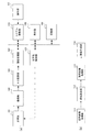
図1(a)は本実施形態の画像処理装置の適用例である撮像装置の概略的なハードウェア構成を示した図であり、図1(b)は本実施形態の撮像装置において広角画像の撮影から高解像度画像の生成までの各機能を示した機能ブロック図である。
先ず図1(a)を参照しながら、本実施形態の撮像装置の構成について説明する。
Hereinafter, preferred embodiments of the present invention will be described in detail with reference to the accompanying drawings. Note that the configurations shown in the following embodiments are merely examples, and the present invention is not limited to the illustrated configurations.
<First embodiment>
In the first embodiment, a region to be increased in resolution is determined based on a wide-angle image acquired by shooting, and a narrow-angle image captured with a narrower angle of view than when a wide-angle image is shot is determined based on the determined region. An example in which a high-resolution image is generated by acquiring a high-resolution image will be described.
FIG. 1A is a diagram illustrating a schematic hardware configuration of an imaging apparatus as an application example of the image processing apparatus according to the present embodiment, and FIG. 1B is a diagram illustrating a wide-angle image of the imaging apparatus according to the present embodiment. FIG. 3 is a functional block diagram illustrating functions from photographing to generation of a high-resolution image.
First, the configuration of the imaging apparatus according to the present embodiment will be described with reference to FIG.

図1(a)において、光学系101は、ズームレンズとフォーカスレンズとシフトレンズとを有して構成されるレンズ群、絞り調整機構、および、シャッター機構等を備えている。この光学系101は、撮像部102に到達する被写体像の倍率やピント位置、光量等を調整する。撮像部102は、光学系101を通過して撮像面上に形成された被写体像を光電変換して電気信号に変換するCCDやCMOSセンサ等の光電変換素子を有する。A/D変換部103は、撮像部102から入力されたアナログ撮像信号をデジタルの画像データに変換する。   In FIG. 1A, the optical system 101 includes a lens group including a zoom lens, a focus lens, and a shift lens, an aperture adjustment mechanism, a shutter mechanism, and the like. The optical system 101 adjusts the magnification, focus position, light amount, and the like of a subject image that reaches the imaging unit 102. The imaging unit 102 includes a photoelectric conversion element such as a CCD or a CMOS sensor that photoelectrically converts a subject image formed on an imaging surface through the optical system 101 and converts the image into an electric signal. The A / D conversion unit 103 converts the analog imaging signal input from the imaging unit 102 into digital image data.

画像処理部104は、通常の画像信号処理の他に、本実施形態に係る高解像度化領域の決定処理、高解像度画像の生成に用いる狭角画像を取得するのに適切な焦点距離の算出、および高解像度画像の生成処理等を行う。これら高解像度化領域の決定処理、適切な焦点距離の算出処理、高解像度画像の生成処理の詳細については後述する。
光学系制御部105は、光学系101のレンズ群に対する駆動制御、絞り調整機構の駆動制御、シャッター機構の駆動制御等を行う。詳細については後述するが、特に本実施形態の場合、光学系制御部105は、システム制御部106による制御の下で、光学系101のズームレンズに対するズームポジション(焦点距離)の制御、シフトレンズに対するシフト駆動制御等を行う。
The image processing unit 104 performs, in addition to the normal image signal processing, the determination processing of the high-resolution area according to the present embodiment, the calculation of the focal length appropriate for acquiring the narrow-angle image used for generating the high-resolution image, And a process of generating a high-resolution image. The details of the processing for determining the high-resolution area, the processing for calculating the appropriate focal length, and the processing for generating the high-resolution image will be described later.
The optical system control unit 105 performs drive control for the lens group of the optical system 101, drive control for the aperture adjustment mechanism, drive control for the shutter mechanism, and the like. Although details will be described later, especially in the case of the present embodiment, the optical system control unit 105 controls the zoom position (focal length) of the optical system 101 with respect to the zoom lens and controls the shift lens under the control of the system control unit 106. It performs shift drive control and the like.

システム制御部106は、本実施形態の装置全体の動作を制御、統括する制御機能部であり、操作部107から送信された指示に基づいて、光学系101や撮像部102の駆動制御、画像処理部104における所定の画像処理の制御を行う。
表示部108は、液晶ディスプレイや有機EL(Electro Luminescence)ディスプレイで構成され、撮像部102で生成された画像や、記録部109から読み出された画像、各種設定メニュー等のユーザインターフェース画面等を表示する。
記録部109は、画像を記録する機能を有し、例えば半導体メモリが搭載されたメモリカードや光磁気ディスク等の回転記録体を収容したパッケージなどを用いた情報記録媒体を含んでもよく、この情報記録媒体が着脱可能になされていてもよい。
画像処理部104、光学系制御部105、システム制御部106、表示部108、および、記録部109は、バスにより接続されており、バスを介して、それらの間で画像データや各種情報のやり取りが行われる。
A system control unit 106 is a control function unit that controls and controls the operation of the entire apparatus according to the present embodiment. Based on an instruction transmitted from the operation unit 107, drive control of the optical system 101 and the imaging unit 102, image processing Control of predetermined image processing in the unit 104 is performed.
The display unit 108 includes a liquid crystal display or an organic EL (Electro Luminescence) display, and displays an image generated by the imaging unit 102, an image read from the recording unit 109, a user interface screen such as various setting menus, and the like. I do.
The recording unit 109 has a function of recording an image, and may include an information recording medium using a package containing a rotating recording body such as a memory card or a magneto-optical disk on which a semiconductor memory is mounted. The recording medium may be detachable.
The image processing unit 104, the optical system control unit 105, the system control unit 106, the display unit 108, and the recording unit 109 are connected by a bus, and exchange image data and various information between them via the bus. Is performed.

次に図1(b)を参照しながら、本実施形態の撮像装置において広角画像の取得から高解像度画像の生成までの各機能ブロックについて説明する。
図1(b)に示した機能ブロックは、広角画像取得部111、領域決定部112、狭角画像取得部113、画像生成部114からなる。本実施形態において、広角画像取得部111と狭角画像取得部113の機能は、例えばシステム制御部106が光学系制御部105を介して光学系101を制御することにより実現される。また、領域決定部112と画像生成部114の機能は、例えば画像処理部104により実行される。
Next, with reference to FIG. 1B, each functional block from the acquisition of a wide-angle image to the generation of a high-resolution image in the imaging device of the present embodiment will be described.
The functional block illustrated in FIG. 1B includes a wide-angle image acquisition unit 111, an area determination unit 112, a narrow-angle image acquisition unit 113, and an image generation unit 114. In the present embodiment, the functions of the wide-angle image acquisition unit 111 and the narrow-angle image acquisition unit 113 are realized, for example, by the system control unit 106 controlling the optical system 101 via the optical system control unit 105. The functions of the area determination unit 112 and the image generation unit 114 are executed by the image processing unit 104, for example.

広角画像取得部111は、本実施形態に係る画像処理において基準画像として用いられる広角画像を取得する。本実施形態の撮像装置において、広角画像取得部111の機能は例えばシステム制御部106により実現される。例えば、システム制御部106は、広角画像取得部111の機能として、光学系制御部105を介して光学系101のズームレンズを制御して焦点距離を短く調整して広角撮影がなされるように制御する。なお、このときの焦点距離は、例えば操作部107を介したユーザからの指示に応じて設定される。そして、この状態で撮像部102により撮像されてA/D変換部103から出力された画像データは、広角画像の情報として画像処理部104に送られる。   The wide-angle image acquisition unit 111 acquires a wide-angle image used as a reference image in the image processing according to the present embodiment. In the imaging device according to the present embodiment, the function of the wide-angle image acquisition unit 111 is realized by the system control unit 106, for example. For example, as a function of the wide-angle image acquisition unit 111, the system control unit 106 controls the zoom lens of the optical system 101 via the optical system control unit 105 to adjust the focal length to be short so that wide-angle shooting is performed. I do. The focal length at this time is set according to, for example, an instruction from the user via the operation unit 107. Then, in this state, the image data captured by the imaging unit 102 and output from the A / D conversion unit 103 is sent to the image processing unit 104 as wide-angle image information.

領域決定部112は、広角画像取得部111にて取得された広角画像の情報を基に、高解像度化する領域を決定する処理を実行する。本実施形態の撮像装置において、領域決定部112の機能は例えば画像処理部104により実現される。なお、高解像度化領域の決定処理の詳細は後述する。同じく詳細は後述するが、高解像度化するとして決定される領域は一つに限らず複数になることが多い。画像処理部104の領域決定部112により決定された高解像度化領域を表す領域情報は、システム制御部106に送られる。   The area determination unit 112 executes a process of determining an area to be increased in resolution based on information of the wide-angle image acquired by the wide-angle image acquisition unit 111. In the imaging device according to the present embodiment, the function of the region determination unit 112 is realized by, for example, the image processing unit 104. The details of the process for determining the high resolution area will be described later. Similarly, the details will be described later, but the number of regions determined to increase the resolution is not limited to one, but is often plural. The area information indicating the high-resolution area determined by the area determining unit 112 of the image processing unit 104 is sent to the system control unit 106.

狭角画像取得部113は、領域決定部112により決定された領域情報を基に狭角画像の撮影を行う。本実施形態の撮像装置において、狭角画像取得部113の機能は例えばシステム制御部106により実現される。例えば、システム制御部106は、先ず、領域決定部112からの領域情報を基に、高解像度化に用いる狭角画像を撮影するための適切な焦点距離を算出する。そして、システム制御部106は、その焦点距離になるように、光学系制御部105を介して光学系101のズームレンズを制御することで高解像度化に用いる狭角画像の撮影を行わせる制御を実行、つまり狭角画像の取得処理を実行する。この狭角画像取得処理の詳細については後述する。なお、領域決定部112によって高解像度化する領域として複数の領域が決定された場合、狭角画像取得部113は、それら複数の各領域に対応した複数の狭角画像を取得する。この狭角画像取得処理において、撮像部102により撮像されてA/D変換部103から出力された画像データは、狭角画像の情報として画像処理部104に送られる。   The narrow-angle image acquisition unit 113 captures a narrow-angle image based on the area information determined by the area determination unit 112. In the imaging device according to the present embodiment, the function of the narrow-angle image acquisition unit 113 is realized by the system control unit 106, for example. For example, the system control unit 106 first calculates an appropriate focal length for photographing a narrow-angle image used for high resolution based on the area information from the area determination unit 112. Then, the system control unit 106 controls the zoom lens of the optical system 101 via the optical system control unit 105 to control the zoom lens of the narrow-angle image to be used for high resolution so as to have the focal length. Execute, that is, execute a narrow-angle image acquisition process. Details of the narrow-angle image acquisition processing will be described later. When a plurality of regions are determined as the regions to be increased in resolution by the region determining unit 112, the narrow-angle image acquiring unit 113 acquires a plurality of narrow-angle images corresponding to the plurality of regions. In the narrow-angle image acquisition process, image data captured by the imaging unit 102 and output from the A / D conversion unit 103 is sent to the image processing unit 104 as information on a narrow-angle image.

画像生成部114は、広角画像取得部111にて取得された広角画像を参照し、狭角画像取得部113で取得した狭角画像を用いて高解像度画像を生成して出力する。本実施形態の撮像装置において、画像生成部114の機能は例えば画像処理部104により実現される。高解像度画像の生成処理の詳細については後述する。画像処理部104の画像生成部114により生成された高解像度画像のデータは、その後、システム制御部106による制御の下で、例えば記録部109に記録されたり、表示部108に表示されたりする。   The image generation unit 114 refers to the wide-angle image acquired by the wide-angle image acquisition unit 111, and generates and outputs a high-resolution image using the narrow-angle image acquired by the narrow-angle image acquisition unit 113. In the imaging device according to the present embodiment, the function of the image generation unit 114 is realized by the image processing unit 104, for example. Details of the high-resolution image generation processing will be described later. The data of the high-resolution image generated by the image generation unit 114 of the image processing unit 104 is then recorded, for example, in the recording unit 109 or displayed on the display unit 108 under the control of the system control unit 106.

図2は、本実施形態の撮像装置における前述した広角画像の取得処理から高解像度画像の生成処理までの処理手順の流れを示したフローチャートである。なお、以下の説明では、各処理のステップS201〜ステップS204をS201〜S204と略記し、このことは後述する他のフローチャートでも同様とする。
以下、本実施形態の撮像装置における広角画像取得処理から高解像度画像生成処理までの各処理の詳細を、図1(b)の機能ブロックと図2のフローチャート等を参照しながら説明する。
FIG. 2 is a flowchart illustrating a flow of a processing procedure from the above-described wide-angle image acquisition processing to the high-resolution image generation processing in the imaging apparatus according to the present embodiment. In the following description, steps S201 to S204 of each process are abbreviated as S201 to S204, and the same applies to other flowcharts described later.
Hereinafter, the details of each process from the wide-angle image acquisition process to the high-resolution image generation process in the imaging apparatus of the present embodiment will be described with reference to the functional blocks of FIG. 1B and the flowchart of FIG.

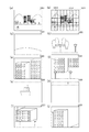
S201において、広角画像取得部111は、撮影したいシーンに対して、本実施形態に係る画像処理において基準画像として用いられる広角画像を撮影することにより取得し、その取得した広角画像のデータを領域決定部112に送る。図3(a)は、広角画像取得部111によりS201において撮影されたシーンの広角画像301の一例を示した図である。   In step S201, the wide-angle image acquisition unit 111 acquires a scene to be photographed by photographing a wide-angle image used as a reference image in image processing according to the present embodiment, and determines data of the acquired wide-angle image in area determination. To the unit 112. FIG. 3A is a diagram illustrating an example of the wide-angle image 301 of the scene captured by the wide-angle image acquisition unit 111 in step S201.

次にS202において、領域決定部112は、広角画像取得部111により取得された広角画像を基に、高解像度化を行う領域を決定する。
ここで、広角画像として撮影されたシーンの情報を使用して高解像度化する領域を決定する際、領域決定部112は、先ず、広角画像301を複数のブロック領域(以下、単にブロックとする。)に分割する。広角画像301のブロック分割する際のブロックサイズと分割数は任意に設定可能であり、図3(b)は、図3(a)の広角画像301を例えばM×Nの複数ブロックに分割した状態の広角画像311の例を示した図である。そして、領域決定部112は、広角画像311のブロック毎に後述する優先度を求め、それらブロック毎の優先度に基づいて高解像度化する領域を決定する。図3(c)は、図3(b)の広角画像311と同様のブロック分割された広角画像321を示しており、高解像度化する領域の一例として領域322と領域323とが決定された例を示している。
Next, in step S <b> 202, the region determination unit 112 determines a region for which the resolution is to be increased based on the wide-angle image acquired by the wide-angle image acquisition unit 111.
Here, when determining an area to be increased in resolution using information of a scene captured as a wide-angle image, the area determination unit 112 first sets the wide-angle image 301 to a plurality of block areas (hereinafter simply referred to as blocks). ). The block size and the number of divisions when the wide-angle image 301 is divided into blocks can be arbitrarily set. FIG. 3B shows a state in which the wide-angle image 301 in FIG. 3A is divided into a plurality of M × N blocks, for example. FIG. 3 is a diagram showing an example of a wide-angle image 311. Then, the area determination unit 112 obtains a priority, which will be described later, for each block of the wide-angle image 311 and determines an area to be increased in resolution based on the priority for each block. FIG. 3C shows a wide-angle image 321 divided into blocks similar to the wide-angle image 311 in FIG. 3B, in which an area 322 and an area 323 are determined as an example of an area to be increased in resolution. Is shown.

図4は、図2のS202で行われるブロック分割からブロック毎の優先度に基づく高解像度化領域の決定処理までの詳細を示したフローチャートである。
先ず、S401において、領域決定部112は、図3(b)に示したように広角画像311を例えばM×Nの複数ブロックに分割する。
次に、S402において、領域決定部112は、ブロック毎に画像の特徴に応じた評価値を求め、それらブロック毎の評価値を基に、高解像化する領域を決定する際の優先度を算出する。本実施形態の場合、各ブロックの画像の特徴に応じた評価値としては、コントラスト情報、顕著度情報、特定の被写体の認識結果の信頼度情報等を用いるとする。
FIG. 4 is a flowchart showing details from the block division performed in S202 of FIG. 2 to the process of determining a high-resolution area based on the priority of each block.
First, in S401, the area determination unit 112 divides the wide-angle image 311 into a plurality of M × N blocks, for example, as shown in FIG.
Next, in S402, the area determination unit 112 obtains an evaluation value corresponding to the feature of the image for each block, and determines a priority when determining a high-resolution area based on the evaluation value for each block. calculate. In the case of the present embodiment, it is assumed that contrast information, saliency information, reliability information of a recognition result of a specific subject, and the like are used as evaluation values according to the characteristics of the image of each block.

それぞれ詳細については後述するが、本実施形態において、領域決定部112は、ブロック毎のコントラスト情報として、エッジ強度特性を表す情報を取得する。エッジ強度特性は被写体領域のテクスチャの有無を判定するために用いられ、領域決定部112は、エッジ強度が大きい領域ほどテクスチャが多い領域であると判断する。また本実施形態において、顕著度情報は、視覚的に目立つ度合いを表す情報である。領域決定部112は、顕著度情報として、例えば画像内の被写体領域の特徴とその周辺の被写体領域の特徴との差分情報を取得する。顕著度情報としての差分情報は、視覚的に目立つ領域かどうかの判定に用いられ、領域決定部112は、顕著度情報(差分情報)が大きくなるほど、視覚的に目立つ領域であると判断する。また、認識結果の信頼度情報としては、特定の被写体の検出及び認識においてその認識結果の信頼度を表す情報が取得される。なお本実施形態では、特定の被写体として例えば空の領域を検出および認識する例を挙げており、領域決定部112は、画像から検出した被写体領域が空領域であると認識した際の認識結果の信頼度情報を取得する。   Although details will be described later, in the present embodiment, the region determination unit 112 acquires information representing edge intensity characteristics as contrast information for each block. The edge strength characteristic is used to determine the presence or absence of a texture in the subject area, and the area determination unit 112 determines that an area with a higher edge strength is an area with more texture. Further, in the present embodiment, the saliency information is information indicating a degree of visually conspicuousness. The region determination unit 112 acquires, for example, difference information between the feature of the subject region in the image and the features of the subject regions in the vicinity thereof as the saliency information. The difference information as the saliency information is used to determine whether or not the area is a visually conspicuous area, and the area determination unit 112 determines that the greater the saliency information (difference information), the more visually the area is prominent. In addition, as the reliability information of the recognition result, information representing the reliability of the recognition result in the detection and recognition of the specific subject is obtained. In the present embodiment, an example is described in which an empty area is detected and recognized as a specific subject, for example. The area determination unit 112 determines the recognition result when the subject area detected from the image is recognized as a sky area. Get reliability information.

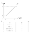
図5(a)は、領域決定部112において、コントラスト情報に応じた優先度を求める際に用いられるグラフ501を示した図である。グラフ501は、下限値から上限値までの間で、コントラスト情報の値が高くなるほど優先度の値も高くなる特性となされている。下限値以下のコントラスト情報に対しては優先度の下限値が設定され、上限値以上のコントラスト情報に対しては優先度の上限値が設定される。また、図5(b)は、領域決定部112において、顕著度情報に応じた優先度を求める際に用いられるグラフ502を示した図である。グラフ502は、下限値から上限値までの間で、顕著度情報の値が高くなるほど優先度の値も高くなる特性となされている。下限値以下の顕著度情報に対しては優先度の下限値が設定され、上限値以上の顕著度情報に対しては優先度の上限値が設定される。また、図5(c)は、領域決定部112において、例えば空領域の検出および認識が行われた場合の認識結果の信頼度情報に応じた優先度を求める際に用いられるグラフ503を示した図である。グラフ503は、下限値から上限値までの間で、空領域の認識結果の信頼度情報の値が高くなるほど優先度の値が低くなる特性となされている。下限値以下の信頼度情報に対しては優先度の上限値が設定され、上限値以上の信頼度情報に対しては優先度の下限値が設定される。なお図5(c)は画像の特徴の変化が少ない空領域が対象となされた場合の例であり、逆に、画像の特徴の変化が大きい他の被写体(例えば人物の顔等)が認識対象である場合には信頼度情報の値が高くなるほど優先度の値が高くなる特性となされてもよい。また、図5(d)は、コントラスト情報、顕著度情報、空領域の認識結果の信頼度情報に対してそれぞれ付与される重みを示した表540である。領域決定部112は、コントラスト情報、顕著度情報、空領域の認識結果の信頼度情報に対しては、それぞれ表540に示した重みを付与する。   FIG. 5A is a diagram showing a graph 501 used when the area determination unit 112 obtains a priority according to contrast information. The graph 501 has a characteristic in which the higher the value of the contrast information, the higher the priority value between the lower limit and the upper limit. A lower limit of the priority is set for contrast information lower than the lower limit, and an upper limit of priority is set for contrast information higher than the upper limit. FIG. 5B is a diagram showing a graph 502 used when the area determination unit 112 obtains a priority according to saliency information. The graph 502 has such a characteristic that, from the lower limit value to the upper limit value, the priority value increases as the value of the saliency information increases. A lower limit value of priority is set for saliency information equal to or less than the lower limit value, and an upper limit value of priority is set for saliency information equal to or more than the upper limit value. FIG. 5C shows a graph 503 used when the area determination unit 112 obtains a priority according to the reliability information of the recognition result when the sky area is detected and recognized, for example. FIG. The graph 503 has a characteristic that, from the lower limit value to the upper limit value, the priority value decreases as the value of the reliability information of the recognition result of the sky region increases. An upper limit of the priority is set for reliability information equal to or lower than the lower limit, and a lower limit of priority is set for reliability information equal to or higher than the upper limit. Note that FIG. 5C shows an example in which a sky region with little change in image features is targeted. Conversely, another subject (for example, a person's face, etc.) with large changes in image features is to be recognized. In the case of, the characteristic may be such that the higher the value of the reliability information, the higher the value of the priority. FIG. 5D is a table 540 showing weights respectively given to the contrast information, the saliency information, and the reliability information of the recognition result of the sky area. The region determining unit 112 assigns the weights shown in Table 540 to the contrast information, the saliency information, and the reliability information of the recognition result of the sky region.

以下、領域決定部112において、コントラスト情報、顕著度情報、特定の被写体の認識結果の信頼度情報等に応じてそれぞれ優先度を設定する処理について、詳細に説明する。
コントラスト情報を基に優先度を設定する場合、領域決定部112は、広角画像311に対してバンドパスフィルタ処理を行うことでエッジ強度を検出し、式(1)を用いて、各ブロックのエッジ強度の積分値Frを、コントラスト情報として算出する。なお、式中の(i,j)はブロック内の座標であり、fr(i,j)は注目ブロック内の各座標におけるエッジ強度値、Frは注目ブロックの各座標のエッジ強度の積分値(コントラスト情報)である。
Hereinafter, the process of setting the priorities in the region determining unit 112 according to the contrast information, the saliency information, the reliability information of the recognition result of the specific subject, and the like will be described in detail.
When setting the priority based on the contrast information, the area determination unit 112 detects the edge strength by performing band-pass filter processing on the wide-angle image 311, and uses the equation (1) to detect the edge strength of each block. The integrated value Fr of the intensity is calculated as contrast information. In the expression, (i, j) is a coordinate in the block, fr (i, j) is an edge intensity value at each coordinate in the target block, and Fr is an integral value of an edge intensity of each coordinate in the target block ( Contrast information).
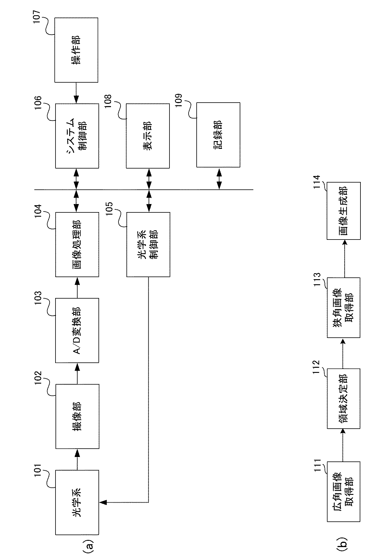
Figure 2020009099
Figure 2020009099

ここで、エッジ強度が大きくテクスチャが多い被写体領域の場合には、エッジ強度の積分値が大きくなり、コントラスト情報の値が大きくなる。また、広角画像311内にテクスチャが多い被写体がある場合、その被写体領域は高解像度な画像であることが望ましい。このため、領域決定部112は、図5(a)に示したグラフ501を用いることにより、広角画像311内でテクスチャが多い被写体領域、つまりコントラスト情報の値が高い領域については高い優先度を設定する。一方、エッジ強度が小さくテクスチャが少ない被写体領域の場合には、エッジ強度の積分値が小さくなり、コントラスト情報の値が小さくなる。また、広角画像311内でテクスチャが少ない被写体がある場合、その被写体領域は高解像度な画像である必要性は低いと考えて差し支えない。このため、領域決定部112は、図5(a)に示したグラフ501を用いることにより、広角画像311内でテクスチャが少ない被写体領域、つまりコントラスト情報の値が低い領域については低い優先度を設定する。   Here, in the case of a subject region having a large edge strength and a large amount of texture, the integral value of the edge strength increases, and the value of the contrast information increases. When there is a subject having many textures in the wide-angle image 311, it is preferable that the subject region is a high-resolution image. For this reason, the area determination unit 112 sets a high priority for a subject area having a large number of textures in the wide-angle image 311, that is, an area having a high contrast information value by using the graph 501 shown in FIG. I do. On the other hand, in the case of a subject area having a small edge strength and a small texture, the integrated value of the edge strength is small and the value of the contrast information is small. Further, when there is a subject having a small texture in the wide-angle image 311, it may be considered that the subject region is not necessarily required to be a high-resolution image. For this reason, the area determination unit 112 sets a low priority for a subject area having a small texture in the wide-angle image 311, that is, an area having a low contrast information value by using the graph 501 shown in FIG. I do.

また被写体の顕著度情報を基に優先度を設定する場合、領域決定部112は、顕著度情報として、着目ブロックの特徴量とその周辺のブロックの特徴量との差分を算出する。本実施形態において、ブロックの特徴量は、ブロック内の輝度値、色相値、エッジ強度の少なくとも一つ以上を含むものとする。領域決定部112は、これらの特徴量に対し、下記の式(2)により各ブロックの特徴量の差の絶対値(SAD:Sum of Abusolute Difference)を算出する。なお、式中のfvA(i,j)は注目ブロック内の各座標における特徴量、fvB(i,j)は周辺ブロック内の各座標の特徴量、Fvは特徴量の差分の絶対値である。 When the priority is set based on the saliency information of the subject, the area determination unit 112 calculates, as the saliency information, a difference between the feature amount of the block of interest and the feature amounts of blocks around the block. In the present embodiment, it is assumed that the feature amount of a block includes at least one of a luminance value, a hue value, and an edge strength in the block. The area determination unit 112 calculates an absolute value (SAD: Sum of Absolute Difference) of the difference between the feature amounts of each block with respect to these feature amounts according to the following equation (2). In the expression, fv A (i, j) is a feature amount at each coordinate in the target block, fv B (i, j) is a feature amount at each coordinate in the peripheral block, and Fv is an absolute value of a difference between the feature amounts. It is.

Figure 2020009099
Figure 2020009099

ここで、着目ブロックとその周辺ブロックの特徴量の差分が大きい場合には、それらブロック間の相関が低いと考えられる。そして、ブロック間の相関が低い場合、それらブロックを含む被写体領域は、視覚的に目立つ被写体の領域であると考えられ、その被写体領域については高解像度な画像を生成することが望ましい。このため、領域決定部112は、図5(b)に示したグラフ502を用いることで、ブロック間の相関が低い被写体領域、つまり着目ブロックと周辺ブロックの特徴量の差分絶対値である顕著度情報の値が高い領域には高い優先度を設定する。一方、着目ブロックと周辺ブロックの特徴量の差分が小さい場合には、それらブロック間の相関が高いと考えられる。この場合、それらブロックを含む被写体領域は視覚的にさほど目立つ被写体の領域でないと考えられ、その被写体領域は高解像度な画像である必要性は低いと考えて差し支えない。したがって、領域決定部112は、図5(b)のグラフ502を基に、ブロック間の相関が高い被写体領域、つまり顕著度情報の値が低い領域には低い優先度を設定する。なお前述の説明では、差分絶対値であるSADを用いた相関の算出方法の例を挙げたが、これに限定されるものではなく、他の方式を使用してもよい。   Here, when the difference between the feature amounts of the target block and its surrounding blocks is large, the correlation between those blocks is considered to be low. When the correlation between the blocks is low, the subject area including the blocks is considered to be a visually prominent subject area, and it is desirable to generate a high-resolution image of the subject area. For this reason, the region determination unit 112 uses the graph 502 shown in FIG. 5B to calculate the saliency, which is the absolute value of the difference between the feature amounts of the subject region having a low correlation between the blocks, ie, the target block and the peripheral blocks. A high priority is set for an area having a high information value. On the other hand, when the difference between the feature amounts of the target block and the peripheral blocks is small, it is considered that the correlation between the blocks is high. In this case, the subject area including these blocks is not considered to be a visually prominent subject area, and the subject area need not be a high-resolution image. Therefore, based on the graph 502 of FIG. 5B, the region determination unit 112 sets a low priority to a subject region having a high correlation between blocks, that is, a region having a low value of saliency information. In the above description, an example of the method of calculating the correlation using the SAD, which is the absolute difference value, has been described. However, the present invention is not limited to this, and another method may be used.

また、特定の被写体の認識結果の信頼度情報を基に優先度を設定する場合、領域決定部112は、先ず、各ブロックにおける特徴量として輝度、色相、エッジ量を算出する。さらに、領域決定部112は、それらブロックの各特徴量を基に、認識対象となされている領域が特定の被写体領域とみなす範囲に合致するかどうかを特徴量毎に判定し、それぞれ合致の度合いに応じた信頼度情報を算出する。そして、領域決定部112は、それら特徴量毎に算出した信頼度情報を例えば乗算し、その乗算後の情報を最終的な信頼度情報として取得する。本実施形態の場合、認識対象の特定の被写体領域として空領域を例に挙げている。なお、空領域等を認識する技術としては、例えば特開2015−32966号公報等に記載された技術を用いることができる。ここで、空領域は、一般に、輝度が高いことが多く、色相としては空の青や雲の白等の所定の色相範囲であることが多く、またエッジ量は少ないことが多い。このため、空領域が認識対象となされている場合、認識結果の信頼度情報としては、輝度値が高く、色相が所定の色相範囲であり、エッジ量が少ないほど高くなる値が設定される。そして、空領域は高解像度な画像である必要性が低いと考えられる。したがって、領域決定部112は、図5(c)に示したグラフ503を基に、空領域とみなす範囲に合致する度合いが高い領域、つまり空領域の認識結果の信頼度情報が高い領域については、低い優先度を設定する。一方、領域決定部112は、図5(c)のグラフ503を基に、空領域とみなす範囲に合致する度合いが低い領域、つまり空領域の認識結果の信頼度情報が低い領域については、高い優先度を設定する。   When setting the priority based on the reliability information of the recognition result of the specific subject, the area determination unit 112 first calculates the luminance, the hue, and the edge amount as the feature amount in each block. Further, the region determination unit 112 determines, for each feature amount, whether or not the region to be recognized matches a range considered as a specific subject region based on the feature amounts of the blocks. Is calculated in accordance with. Then, the area determination unit 112 multiplies, for example, the reliability information calculated for each of the feature amounts, and acquires the information after the multiplication as final reliability information. In the case of the present embodiment, a sky area is taken as an example of a specific subject area to be recognized. In addition, as a technique for recognizing a sky area or the like, a technique described in, for example, JP-A-2015-32966 can be used. Here, the sky area generally has high luminance in many cases, has a hue in a predetermined hue range such as blue in the sky or white in clouds, and has a small edge amount in many cases. Therefore, when the sky area is a recognition target, a value that is higher as the luminance value is higher, the hue is within a predetermined hue range, and the edge amount is smaller is set as the reliability information of the recognition result. Then, it is considered that the necessity of the sky region is not a high-resolution image. Therefore, based on the graph 503 shown in FIG. 5C, the region determining unit 112 determines, for a region having a high degree of matching with the range regarded as a sky region, that is, a region having high reliability information of the recognition result of the sky region. , Set a lower priority. On the other hand, based on the graph 503 in FIG. 5C, the area determination unit 112 sets a high degree for an area having a low degree of matching with a range regarded as a sky area, that is, an area having low reliability information of the recognition result of the sky area. Set the priority.

前述したように、図4のS402において、領域決定部112は、コントラスト情報、顕著度情報、認識結果の信頼度情報を、それぞれ優先度を設定する際の評価値として求め、それら評価値毎に優先度を算出する。
次にS403において、領域決定部112は、下記の式(3)を用い、S402で評価値毎に算出した優先度に重み付けを行って、ブロック毎の優先度W(M,N)を算出する。なお式中のnは取得された評価値の数を表し、anは評価値毎に設定された優先度である。また式中のαnは、評価値毎の優先度に対して設定された重みであり、例えば図5(d)の表504に示した重みが用いられる。被写体のテクスチャの有無を表しているコントラスト情報は高解像度化する領域を決定する際に重要であるため、図5(d)の表504では、当該コントラスト情報に対する重みが一番大きい値に設定されている。なお、重みはユーザが指定して決めてもよい。
As described above, in S402 of FIG. 4, the region determination unit 112 obtains the contrast information, the saliency information, and the reliability information of the recognition result as evaluation values when setting priorities, and for each of these evaluation values. Calculate the priority.
Next, in S403, the area determination unit 112 calculates the priority W (M, N) for each block by weighting the priority calculated for each evaluation value in S402 using the following equation (3). . Note wherein n represents the number of the obtained evaluation value, a n is the priority set for each evaluation value. Further, α n in the expression is a weight set for the priority for each evaluation value, and for example, the weight shown in a table 504 in FIG. 5D is used. Since the contrast information indicating the presence / absence of the texture of the subject is important in determining the area to be increased in resolution, the weight for the contrast information is set to the largest value in the table 504 in FIG. ing. The weight may be specified by the user.

Figure 2020009099
Figure 2020009099

次にS404において、領域決定部112は、S403で式(3)によりブロック毎に決定した優先度W(M,N)の中から、優先度W(M,N)の値が例えば所定の閾値以上となっている優先度W(M,N)の高いブロックを選択する。そして、領域決定部112は、選択したブロックに対応した領域を、狭角画像を撮影して高解像度化する領域として決定する。例えば図3(c)の例に示したように、広角画像321の中で例えば領域322や領域323が高解像度化する領域として決定される。   Next, in S404, the region determination unit 112 determines that the value of the priority W (M, N) is, for example, a predetermined threshold value from among the priorities W (M, N) determined for each block by Expression (3) in S403. The block having the higher priority W (M, N) is selected. Then, the region determining unit 112 determines a region corresponding to the selected block as a region to be photographed with a narrow-angle image to increase the resolution. For example, as shown in the example of FIG. 3C, in the wide-angle image 321, for example, the region 322 and the region 323 are determined as the regions to be increased in resolution.

前述したようにして、領域決定部112では、コントラスト情報、顕著度情報、特定の被写体の認識結果の信頼度情報等の評価値に応じて設定した優先度を基に、狭角画像を撮影して高解像度化する領域を決定する。具体例として、被写体のテクスチャが多く、顕著度も高い被写体領域を挙げて説明する。例えばテクスチャが多い被写体領域は狭角画像を撮影して高解像度化することに効果のある領域であると考えられる。また、顕著度が高い被写体領域は目立つ領域であり、ユーザの目に留まる可能性が高く、狭角画像を撮影して高解像度化することに効果のある領域であると考えられる。したがって、領域決定部112では、被写体のテクスチャが多い被写体領域や、顕著度の高い被写体領域について優先度を高く設定して、高解像化する領域として決定する。一方、テクスチャが少なく、顕著度も低い領域の場合、広角画像と狭角画像での差が少なく、ユーザの目にも留まりにくい領域であると考えられる。このため、領域決定部112では、テクスチャが少なく、顕著度も低い領域について優先度を低く設定して、高解像度化する領域として決定しないようにする。   As described above, the area determination unit 112 captures a narrow-angle image based on a priority set according to an evaluation value such as contrast information, saliency information, and reliability information of a recognition result of a specific subject. To determine the area to be increased in resolution. As a specific example, a description will be given of a subject region in which the texture of the subject is large and the degree of saliency is high. For example, a subject region with many textures is considered to be a region that is effective in capturing a narrow-angle image and increasing the resolution. In addition, the subject region having a high degree of saliency is a conspicuous region, is likely to be noticed by the user, and is considered to be a region that is effective in capturing a narrow-angle image and increasing the resolution. Therefore, the region determination unit 112 sets a high priority for a subject region having a large texture of the subject or a subject region with a high degree of saliency, and determines the region to be a high resolution region. On the other hand, in the case of an area having a small texture and a low saliency, the difference between the wide-angle image and the narrow-angle image is small, and it is considered that the area is difficult for the user to see. For this reason, the area determination unit 112 sets a low priority for an area having a small texture and a low saliency, so that the area is not determined as a high resolution area.

図2のフローチャートに説明を戻す。S202の後、撮像装置の処理はS203に進む。
S203に進むと、狭角画像取得部113は、前述のようにS202で決定された高解像度化する領域を基に狭角画像の撮影を行う。本実施形態において、狭角画像を撮影する際には、光学系101のズームレンズの焦点距離を調整して撮影画角を狭角にした上でシフトレンズのシフト駆動を行って撮影画角の撮影位置を移動させるようして撮影を行う。
The description returns to the flowchart of FIG. After S202, the process of the imaging device proceeds to S203.
In step S203, the narrow-angle image acquisition unit 113 captures a narrow-angle image based on the region to be increased in resolution determined in step S202 as described above. In the present embodiment, when shooting a narrow-angle image, the focal length of the zoom lens of the optical system 101 is adjusted to reduce the shooting angle of view, and then the shift lens is shifted to perform the shift operation. Shooting is performed by moving the shooting position.

図6(a)〜図6(h)は、広角画像を参照して高解像度化する領域の狭角画像を撮影する様子を説明する図である。図6(a)は図3(a)に示したのと同様の広角画像601を示した図である。図6(b)はS203においてズームアップにより狭角にした後にレンズのシフト駆動により狭角の撮影画角を移動させる際の移動順序(図中に矢印で示す移動順序)の一例を示した図である。なお、図6(b)では図3(b)の例と同様にブロック分割された広角画像611を示し、図中に矢印で示したように、移動順序は各ブロックの配列に応じた順序になされているが、移動順序はこの例に限定されるものではない。また、図6(c)は図3(c)と同様の広角画像621及びその広角画像621内で高解像化するとして決定された領域622,623と、例えば高解像度化する領域622を取得する際に狭角の撮影画角で写っている狭角画像631とを示した図である。なお、図6(c)において広角画像621内の特徴点624と狭角画像631内の特徴点632については後述する。図6(c)の領域622に対応した高解像度画像を生成する場合には、例えば図6(d)に示す狭角画像641、図6(f)に示す狭角画像643、図6(g)に示す狭角画像644が取得される。また、図6(c)の領域623に対応した高解像度画像を生成する場合には、例えば図6(e)に示す狭角画像642、図6(h)に示す狭角画像645が取得される。なお、図6(d)〜図6(h)の各図の並び順は、狭角画像が取得される順番に応じている。   FIGS. 6A to 6H are diagrams illustrating a state in which a narrow-angle image of a region to be increased in resolution is captured with reference to a wide-angle image. FIG. 6A is a diagram showing a wide-angle image 601 similar to that shown in FIG. FIG. 6B is a diagram illustrating an example of a moving order (moving order indicated by an arrow in the drawing) when the narrow angle of view is moved by shift driving of the lens after narrowing the angle by zooming up in S203. It is. Note that FIG. 6B shows a wide-angle image 611 divided into blocks in the same manner as the example of FIG. 3B, and as shown by arrows in the figure, the moving order is an order according to the arrangement of each block. However, the order of movement is not limited to this example. 6C shows a wide-angle image 621 similar to that shown in FIG. 3C and regions 622 and 623 determined to be high-resolution within the wide-angle image 621, and a region 622 to be increased in resolution, for example. FIG. 6 is a diagram showing a narrow-angle image 631 which is captured at a narrow-angle shooting angle of view when performing the operation. Note that, in FIG. 6C, a feature point 624 in the wide-angle image 621 and a feature point 632 in the narrow-angle image 631 will be described later. When generating a high-resolution image corresponding to the region 622 in FIG. 6C, for example, a narrow-angle image 641 shown in FIG. 6D, a narrow-angle image 643 shown in FIG. The narrow-angle image 644 shown in FIG. When generating a high-resolution image corresponding to the area 623 in FIG. 6C, for example, a narrow-angle image 642 shown in FIG. 6E and a narrow-angle image 645 shown in FIG. You. Note that the order of arrangement in each of FIGS. 6D to 6H depends on the order in which narrow-angle images are acquired.

このように、狭角画像取得部113は、光学系101のズームレンズを制御して撮影画角を狭角にした上で、その狭角の撮影画角が、図6(b)の広角画像611に対応した撮影範囲をカバーする移動順序で移動するようにシフトレンズをシフト駆動させる。そして、狭角画像取得部113は、狭角の撮影画角の移動させている際に、領域決定部112にて決定された高解像度化する領域が撮影画角内に写っている画像を撮影するようにする。ここで高解像度化する領域が狭角画像に写っているか否かの判定は、例えば図6(c)の広角画像621の高解像度化する領域の特徴点(例えば領域622の特徴点624)と、狭角画像631の特徴点(例えば特徴点632)との類似度を比較することで行う。類似度としては、広角画像621の高解像度化する領域622内の特徴点624と、狭角画像631に写っている特徴点632とで、対応した特徴情報が所定の割合以上ある場合に類似度が高いと判断する。また高解像度化する領域が狭角画像内にあるか否かを判定する際の特徴点としては、広角画像621と狭角画像631の各々でバンドパスフィルタやエッジ検出器等により検出される信号の変化が大きい領域やエッジの強度が大きい領域等を用いることができる。   As described above, the narrow-angle image acquisition unit 113 controls the zoom lens of the optical system 101 to narrow the shooting angle of view, and then changes the narrow angle of view to the wide-angle image in FIG. The shift lens is driven to shift so as to move in a moving order covering the photographing range corresponding to 611. Then, the narrow-angle image acquisition unit 113 captures an image in which the region to be increased in resolution determined by the region determination unit 112 is included in the shooting angle of view while moving the narrow-angle shooting angle of view. To do it. Here, it is determined whether or not the region to be increased in resolution is included in the narrow-angle image, for example, by determining the feature point of the region to be increased in resolution of the wide-angle image 621 in FIG. This is performed by comparing the similarity with a feature point (for example, feature point 632) of the narrow-angle image 631. As the similarity, the feature point 624 in the area 622 of the wide-angle image 621 to be increased in resolution and the feature point 632 in the narrow-angle image 631 have a similarity when the corresponding feature information has a predetermined ratio or more. Is determined to be high. The characteristic points for determining whether or not the region to be increased in resolution is in the narrow-angle image include a signal detected by a band-pass filter, an edge detector, or the like in each of the wide-angle image 621 and the narrow-angle image 631. And a region having a large edge strength can be used.

具体的には、狭角画像取得部113は、広角画像611内で高解像度化する領域の特徴点624と、狭角画像631内の特徴点632との間で相関の度合いを計算することで画像間の対応関係の有無の検出を行う。相関の度合いとしては、例えば式(4)により算出される相関値RSADを用いる。なお、式中のf(i,j)は広角画像内の各座標の画素値、g(i,j)は狭角画像内の各座標の画素値である。 Specifically, the narrow-angle image acquisition unit 113 calculates the degree of correlation between the feature point 624 of the region to be increased in resolution in the wide-angle image 611 and the feature point 632 in the narrow-angle image 631. The presence or absence of the correspondence between the images is detected. As the degree of correlation, for example, a correlation value R SAD calculated by equation (4) is used. In the expression, f (i, j) is a pixel value of each coordinate in the wide-angle image, and g (i, j) is a pixel value of each coordinate in the narrow-angle image.

Figure 2020009099
Figure 2020009099

そして、狭角画像取得部113は、算出した相関値RSADが閾値以下となる特徴点の組を対応点と判定し、類似度が高いと判断する。図6(c)の例では、広角画像621の高解像度化する領域の特徴点624と、狭角画像631内の特徴点632とが相関の高い点を示しており、これらの類似度が高いと判断される。狭角画像取得部113は、このような類似度の高い特徴点が所定の割合以上含まれる場合に、狭角画像には高解像度化する領域が写っていると判定し、その狭角画像を取得して記録する。前述した図6(d)〜図6(h)に示した各狭角画像641〜645が、記録される狭角画像となる。 Then, the narrow-angle image acquisition unit 113 determines that a set of feature points for which the calculated correlation value R SAD is equal to or smaller than the threshold is a corresponding point, and determines that the similarity is high. In the example of FIG. 6C, the feature point 624 of the region of the wide-angle image 621 whose resolution is to be increased and the feature point 632 in the narrow-angle image 631 have a high correlation, and the similarity is high. Is determined. When such a high similarity feature point is included in a predetermined ratio or more, the narrow-angle image acquisition unit 113 determines that the narrow-angle image includes an area to be increased in resolution, and determines that narrow-angle image. Obtain and record. The narrow-angle images 641 to 645 shown in FIGS. 6D to 6H are recorded narrow-angle images.

前述した例では、シフトレンズをシフト駆動させる撮影方法により、広角画像内の高解像度化する領域に対応した狭角画像の撮影を実現したが、他の手法により高解像度化する領域に対応した狭角画像の撮影を実現してもよい。例えばいわゆる手持ち撮影がなされている際の手振れ量を基に、狭角時の撮影画角の移動方向と移動量を算出して、それら移動方法と移動量を基に、高解像度化する領域に対応した狭角画像の撮影を行うようにしてもよい。この場合、狭角画像取得部113は、例えば、光学系101の焦点距離と、図1には不図示の手振れ検出センサ等により検出される手振れ量とを基に、狭角時の撮影画角の移動方向と移動量を算出する。さらに、狭角画像取得部113は、狭角時の撮影画角の移動方法と移動量を基に、狭角時の撮影画角により撮影される範囲が、広角画像が撮影された範囲内の何れの範囲に対応しているかを算出する。そして、狭角画像取得部113は、狭角の撮影画角が手振れにより移動した撮影範囲が、広角画像の撮影範囲内で高解像度化する領域に対応した範囲になった時に狭角画像の撮影を実行する。またこの例の場合も、前述同様の特徴点の比較に基づく類似度判定を行って、広角画像の高解像度化する領域が狭角画像に写っているか否かの判定を行ってもよい。また手持ち撮影が行われる場合、手振れによる画質劣化が生ずる虞があり、手振れによって撮像部102の撮像面上で光学像が移動する移動量は例えば被写体までの距離と、光学系101の焦点距離と、手振れ量とから算出可能である。このため、狭角画像取得部113は、狭角画像を撮影する際には、手振れによる画質への影響を極力少なくできるシャッター速度で撮影を実行する。一般に、下記の式(5)で算出されるシャッター速度Tvより速い速度で撮影すれば、手振れによる画質劣化が略々見えなくなるため、狭角画像取得部113は、式(5)の算出値を基準値とし、それより速いシャッター速度で狭角画像の撮影を行うようにする。なお式中のfは光学系101の焦点距離である。   In the above-described example, the narrow-angle image corresponding to the region where the resolution is increased in the wide-angle image is realized by the imaging method in which the shift lens is shift-driven, but the narrow-angle image corresponding to the region where the resolution is increased by another method is realized. Shooting of a corner image may be realized. For example, based on the amount of camera shake when so-called hand-held shooting is being performed, the moving direction and moving amount of the shooting angle of view at the time of a narrow angle are calculated, and based on the moving method and the moving amount, an area for higher resolution is calculated. A corresponding narrow-angle image may be captured. In this case, for example, the narrow-angle image acquisition unit 113 determines the shooting angle of view at the narrow angle based on the focal length of the optical system 101 and the amount of camera shake detected by a camera shake detection sensor (not shown in FIG. 1). The movement direction and the movement amount of the are calculated. Further, the narrow-angle image acquisition unit 113 determines whether the range captured by the narrow-angle shooting angle of view is within the range where the wide-angle image is captured, based on the method and amount of movement of the narrow-angle shooting angle of view. Calculate which range corresponds to which range. Then, the narrow-angle image acquisition unit 113 captures a narrow-angle image when the shooting range in which the narrow-angle shooting angle of view has moved due to camera shake becomes a range corresponding to an area for increasing the resolution within the shooting range of the wide-angle image. Execute Also in this example, the similarity determination based on the comparison of the feature points as described above may be performed to determine whether or not the area of the wide-angle image to be increased in resolution is shown in the narrow-angle image. When hand-held shooting is performed, image quality may be degraded due to camera shake, and the amount of movement of the optical image on the imaging surface of the imaging unit 102 due to camera shake is, for example, the distance to the subject, the focal length of the optical system 101, and the like. , And the amount of camera shake. For this reason, when capturing a narrow-angle image, the narrow-angle image acquisition unit 113 performs capturing at a shutter speed that minimizes the effect on image quality due to camera shake. In general, if the image is taken at a speed higher than the shutter speed Tv calculated by the following equation (5), the image quality deterioration due to camera shake becomes almost invisible, so the narrow-angle image acquisition unit 113 calculates the value calculated by the equation (5). The reference value is set, and a narrow-angle image is shot at a faster shutter speed. Note that f in the equation is the focal length of the optical system 101.

Tv=1/f 式(5)   Tv = 1 / f Equation (5)

前述のようにして、S203において高解像度化する領域に対応した狭角画像の取得がなされた後、撮像装置の処理は図2のS204に進む。
S204において、画像生成部114は、広角画像取得部111が取得した広角画像を参照し、狭角画像取得部113が取得した狭角画像を用いて高解像度画像を生成する。この高解像度画像を生成する処理を図7、図8(a)〜図8(c)を使用して説明する。図7はS204の処理の詳細を示したフローチャートである。図8(a)は広角画像取得部111により取得された前述の図3(a)と同様の広角画像801を示し、図8(b)は狭角画像取得部113により高解像化する領域に対応して取得された狭角画像811の一つを示した図である。図8(c)は図8(a)の広角画像801を拡大した広角画像821と、狭角画像取得部113により取得された狭角画像831との対応関係の説明に用いる図である。なお、図8(c)は拡大された広角画像の一部のみを抜き出して示しており、実際には図8(a)の広角画像801と同じ絵柄が写っている拡大された広角画像である。
As described above, after the narrow-angle image corresponding to the area whose resolution is to be increased is obtained in S203, the process of the imaging apparatus proceeds to S204 in FIG.
In S204, the image generation unit 114 refers to the wide-angle image acquired by the wide-angle image acquisition unit 111, and generates a high-resolution image using the narrow-angle image acquired by the narrow-angle image acquisition unit 113. The process of generating the high-resolution image will be described with reference to FIGS. 7, 8A to 8C. FIG. 7 is a flowchart showing the details of the process of S204. FIG. 8A shows a wide-angle image 801 similar to that of FIG. 3A acquired by the wide-angle image acquisition unit 111, and FIG. 8B shows a region where high resolution is obtained by the narrow-angle image acquisition unit 113. FIG. 13 is a diagram showing one of the narrow-angle images 811 acquired corresponding to FIG. FIG. 8C is a diagram used to explain the correspondence between the wide-angle image 821 obtained by enlarging the wide-angle image 801 in FIG. 8A and the narrow-angle image 831 acquired by the narrow-angle image acquisition unit 113. Note that FIG. 8C shows only a part of the enlarged wide-angle image, which is actually an enlarged wide-angle image showing the same pattern as the wide-angle image 801 in FIG. 8A. .

画像生成部114は、先ず図7のフローチャートのS701において、図8(b)に示した狭角画像811内の被写体の大きさと、図8(a)に示した広角画像801内の被写体の大きさとを合わせるために、図8(c)に示すように広角画像を拡大する。図8(c)の広角画像821は、図8(a)の広角画像801を拡大した広角画像の一部のみを抜き出して示した画像であり、その中の被写体の大きさが、狭角画像831内の被写体の大きさと一致するようになされている。   First, in S701 of the flowchart in FIG. 7, the image generation unit 114 determines the size of the subject in the narrow-angle image 811 shown in FIG. 8B and the size of the subject in the wide-angle image 801 shown in FIG. The wide-angle image is enlarged as shown in FIG. A wide-angle image 821 in FIG. 8C is an image in which only a part of the wide-angle image obtained by enlarging the wide-angle image 801 in FIG. 8A is extracted and the size of the subject in the wide-angle image 801 is a narrow-angle image. 831 so as to match the size of the subject.

次にS702において、画像生成部114は、図8(c)のように拡大した広角画像821と、狭角画像831とに対し、画像内の特徴点を抽出する処理を行う。特徴点抽出は、前述したS203で説明したのと同様の手法を用いるとする。
次に、S703において、画像生成部114は、拡大した広角画像821と、狭角画像831とからそれぞれ抽出した特徴点間の相関の度合いを算出することで、それら画像間で対応関係を有する対応点を探索する。相関の度合いの算出の際には、前述した式(4)を用いる。そして対応点探索処理の結果、図8(c)の拡大した広角画像821内の特徴点822と狭角画像831内の特徴点832、同様に広角画像821内の特徴点823と狭角画像831内の特徴点833とが、各々対応関係を有する対応点として探索されたとする。
Next, in step S702, the image generation unit 114 performs a process of extracting a feature point in the image from the wide-angle image 821 and the narrow-angle image 831 that are enlarged as illustrated in FIG. It is assumed that the feature point extraction uses the same method as that described in S203 described above.
Next, in step S703, the image generation unit 114 calculates the degree of correlation between the feature points extracted from the enlarged wide-angle image 821 and the narrow-angle image 831 to obtain a correspondence having a correspondence between the images. Search for points. In calculating the degree of correlation, the above-described equation (4) is used. Then, as a result of the corresponding point search processing, the feature point 822 and the feature point 832 in the enlarged wide-angle image 831 of FIG. 8C, and similarly, the feature point 823 and the narrow-angle image 831 in the wide-angle image 821 are obtained. It is assumed that the feature points 833 within are searched as corresponding points each having a corresponding relationship.

次に、S704において、画像生成部114は、S703で探索した画像間の対応点を基に、広角画像801と狭角画像811との位置合わせを行い、それら広角画像801と狭角画像811を合成して高解像度画像を生成する。なお、画像合成による高解像度画像の生成処理としては、例えば特開2007−164258号公報に記載される手法を用いることができる。この場合、画像生成部114は、合成する両画像の対応する4点以上の特徴点の組み合わせを用いて射影変換式を算出し、その射影変換式を用いて狭角画像を変形した上で、広角画像に対する位置合わせを行う。そして、画像生成部114は、前述のよう射影変換式による変形および位置合わせを行った狭角画像を、広角画像に合成して高解像度画像を生成する。なお、高解像度画像を生成する際に、高解像度化する領域であるにも関わらず、対応する狭角画像が取得されていない場合には、広角画像をそのまま使用して画像を生成する。画像生成部114は、前述のような処理により生成した高解像度画像を出力する。   Next, in step S704, the image generation unit 114 performs positioning between the wide-angle image 801 and the narrow-angle image 811 based on the corresponding points between the images searched in step S703, and generates the wide-angle image 801 and the narrow-angle image 811. Combine to generate a high-resolution image. As a process for generating a high-resolution image by image synthesis, for example, a method described in JP-A-2007-164258 can be used. In this case, the image generation unit 114 calculates a projective transformation formula using a combination of four or more corresponding feature points of both images to be combined, and transforms the narrow-angle image using the projective transform formula. Performs positioning for the wide-angle image. Then, the image generation unit 114 generates a high-resolution image by synthesizing the narrow-angle image, which has been subjected to the transformation and alignment by the projection conversion formula as described above, with a wide-angle image. When a high-resolution image is generated, if a corresponding narrow-angle image is not acquired in spite of an area to be increased in resolution, the image is generated using the wide-angle image as it is. The image generator 114 outputs the high-resolution image generated by the above-described processing.

なお前述の説明では、広角画像に狭角画像を合成して高解像度画像を生成する例を挙げたが、広角画像との合成を行わずに、広角画像を参照して、狭角画像のみを繋ぐように合成することで高解像度画像を生成してもよい。この場合、画像生成部114は、広角画像と狭角画像との間の対応関係を基に、複数の狭角画像の位置関係を算出し、それらの位置関係を基に狭角画像を繋ぎ合わせるように合成することで、高解像度画像を生成する。
その他にも、前述のような広角画像と狭角画像の合成、狭角画像を繋ぎ合わせる合成の処理を行わず、広角画像と狭角画像の対応関係を保持しておき、広角画像の拡大指示がなされた際に、その拡大指示に対応する狭角画像を表示させるようにしてもよい。
In the above description, an example in which a high-resolution image is generated by combining a narrow-angle image with a wide-angle image has been described. However, without combining with the wide-angle image, only the narrow-angle image is referred to by referring to the wide-angle image. A high-resolution image may be generated by combining them so that they are connected. In this case, the image generation unit 114 calculates the positional relationship between the plurality of narrow-angle images based on the correspondence between the wide-angle image and the narrow-angle image, and connects the narrow-angle images based on the positional relationship. To generate a high-resolution image.
In addition, without performing the processing of combining the wide-angle image and the narrow-angle image and the combining processing of joining the narrow-angle images as described above, the correspondence relationship between the wide-angle image and the narrow-angle image is maintained, and an instruction to enlarge the wide-angle image is issued. , A narrow-angle image corresponding to the enlargement instruction may be displayed.

また本実施形態では、高解像度画像を生成する際に、対応する狭角画像がない場合に広角画像を使用して画像を生成する例を挙げたが、広角画像を使用せずに、再度、狭角画像の取得処理を行い、その取得した狭角画像を用いて高解像度画像を生成してもよい。
また本実施形態では、高解像度画像生成の際に、広角画像と狭角画像の対応した特徴点を算出して位置合わせ行ったが、特徴点を使用せず、着目画素周辺の任意の範囲のテンプレートを使用し、ブロック単位で対応する領域を算出して位置合わせを行ってもよい。
Further, in the present embodiment, when generating a high-resolution image, an example is described in which an image is generated using a wide-angle image when there is no corresponding narrow-angle image, but without using a wide-angle image, A narrow-angle image acquisition process may be performed, and a high-resolution image may be generated using the acquired narrow-angle image.
Further, in the present embodiment, when generating a high-resolution image, the corresponding feature points of the wide-angle image and the narrow-angle image are calculated and aligned. However, the feature points are not used, and an arbitrary range around the pixel of interest is used. A template may be used to calculate a corresponding area in block units and perform positioning.

以上説明したように第1実施形態の撮像装置においては、撮影した広角画像を基に高解像度化する領域を決定し、その領域に対応した狭角画像を取得して、高解像度画像を生成している。これにより第1の実施形態の撮像装置によれば、広角画像の中で高解像度化する領域に対応した狭角画像を効率よく取得でき、ユーザの負担が少なく、高解像度画像を取得することができる。   As described above, in the imaging apparatus according to the first embodiment, a region to be increased in resolution is determined based on a captured wide-angle image, a narrow-angle image corresponding to the region is acquired, and a high-resolution image is generated. ing. Thus, according to the imaging apparatus of the first embodiment, a narrow-angle image corresponding to a region to be increased in resolution in a wide-angle image can be efficiently acquired, and a burden on a user is reduced, and a high-resolution image can be acquired. it can.

<第2実施形態>
第2実施形態では、撮影した広角画像と狭角画像とを基に高解像度化する領域を決定し、その決定された領域の高解像度画像を生成するために使用する狭角画像を選択して高解像度画像を生成する例について説明する。第2実施形態に係る撮像装置の構成は前述した図1(a)と同様であるため図示は省略する。
図9は第2実施形態の撮像装置において広角画像と狭角画像を撮像して、高解像度画像を生成するまでの機能ブロックを示した図である。
<Second embodiment>
In the second embodiment, a region to be increased in resolution is determined based on a captured wide-angle image and a narrow-angle image, and a narrow-angle image used to generate a high-resolution image of the determined region is selected. An example of generating a high-resolution image will be described. The configuration of the imaging apparatus according to the second embodiment is the same as that of FIG.
FIG. 9 is a diagram showing functional blocks from capturing a wide-angle image and a narrow-angle image to generating a high-resolution image in the imaging device according to the second embodiment.

図9に示すように、第2実施形態における機能ブロックは、広角画像取得部901、狭角画像取得部902、領域決定部903、画像生成部904からなる。第2実施形態においても、第1実施形態の場合と同様に、広角画像取得部901と狭角画像取得部902の機能は、例えばシステム制御部106が光学系制御部105を介して光学系101を制御することにより実現される。また、領域決定部903と画像生成部904の機能は、例えば画像処理部104により実行される。   As shown in FIG. 9, the functional blocks in the second embodiment include a wide-angle image acquisition unit 901, a narrow-angle image acquisition unit 902, an area determination unit 903, and an image generation unit 904. In the second embodiment, as in the case of the first embodiment, the functions of the wide-angle image acquisition unit 901 and the narrow-angle image acquisition unit 902 are performed by, for example, the system control unit 106 via the optical system control unit 105 and the optical system 101. Is realized by controlling Further, the functions of the region determination unit 903 and the image generation unit 904 are executed by the image processing unit 104, for example.

広角画像取得部901は、第1実施形態の場合と同様に、基準画像として用いられる広角画像を取得する。
狭角画像取得部902は、広角画像取得部901にて広角画像が取得された際の画角の範囲内で複数の狭角画像を取得する。
領域決定部903は、広角画像取得部901で取得された広角画像および狭角画像取得部902で取得された狭角画像の情報を基に、高解像度化する領域を決定する処理を実行する。
画像生成部904は、領域決定部903にて決定された高解像度化する領域の情報を基に、狭角画像取得部902で取得された複数の狭角画像の中から、高解像度化する領域に対応した狭角画像を選択する。そして、画像生成部904は、選択した狭角画像を用い、広角画像取得部901で取得された広角画像を参照して高解像度画像を生成して出力する。
The wide-angle image acquisition unit 901 acquires a wide-angle image used as a reference image, as in the case of the first embodiment.
The narrow-angle image acquisition unit 902 acquires a plurality of narrow-angle images within the range of the angle of view when the wide-angle image acquisition unit 901 acquires a wide-angle image.
The region determination unit 903 executes a process of determining a region to be increased in resolution based on information on the wide-angle image acquired by the wide-angle image acquisition unit 901 and the narrow-angle image acquired by the narrow-angle image acquisition unit 902.
The image generation unit 904 selects a region to be increased in resolution from among the plurality of narrow-angle images acquired by the narrow-angle image acquisition unit 902 based on the information on the region to be increased in resolution determined by the region determination unit 903. Select a narrow-angle image corresponding to. Then, the image generation unit 904 generates and outputs a high-resolution image with reference to the wide-angle image acquired by the wide-angle image acquisition unit 901 using the selected narrow-angle image.

図10は、第2実施形態の撮像装置における広角画像および狭角画像の取得から高解像度画像の生成処理までの処理手順の流れを示したフローチャートである。以下、第2実施形態の撮像装置における広角画像および狭角画像の取得処理から高解像度画像生成処理までの各処理の詳細を、図9の機能ブロックと図10のフローチャート等を参照しながら説明する。   FIG. 10 is a flowchart illustrating a flow of a processing procedure from acquisition of a wide-angle image and a narrow-angle image to generation of a high-resolution image in the imaging apparatus according to the second embodiment. Hereinafter, details of each processing from the acquisition processing of the wide-angle image and the narrow-angle image to the high-resolution image generation processing in the imaging device of the second embodiment will be described with reference to the functional blocks of FIG. 9 and the flowchart of FIG. .

S1001において、広角画像取得部901は、前述した図2のS201と同様にして広角画像を取得する。この広角画像のデータは、狭角画像取得部902を介して領域決定部903に送られる。
次にS1002において、狭角画像取得部902は、撮影したいシーンに対して、高解像度画像を生成するために使用する狭角画像を撮影し、その狭角画像のデータを領域決定部903に送る。第2実施形態においても、前述した第1実施形態で説明したのと同様に、狭角画像の撮影方法としては、シフトレンズのシフト駆動により狭角の撮影画角を移動させる撮影方法や、手持ち撮影時の手振れ量に基づく撮影方法を用いることができる。
In step S1001, the wide-angle image acquisition unit 901 acquires a wide-angle image in the same manner as in step S201 in FIG. The data of the wide-angle image is sent to the area determination unit 903 via the narrow-angle image acquisition unit 902.
Next, in step S1002, the narrow-angle image acquisition unit 902 captures a narrow-angle image used to generate a high-resolution image for a scene to be captured, and sends the data of the narrow-angle image to the region determination unit 903. . In the second embodiment, as described in the first embodiment, as a method for photographing a narrow-angle image, a photographing method in which a narrow-angle photographing field of view is moved by shift driving of a shift lens, a hand-held method, and the like. A shooting method based on the amount of camera shake at the time of shooting can be used.

次にS1003において、領域決定部903は、広角画像取得部901により取得された広角画像と、狭角画像取得部902により取得された狭角画像とを基に、高解像度化を行う領域を決定する。第2実施形態における領域決定部903は、第1実施形態のS202において優先度を設定するのに用いた各情報に加え、広角画像と狭角画像の中の同一被写体領域を比較した際のエッジ強度の差をも用いて優先度を設定して、高解像度化する領域を決定する。すなわち第2実施形態では、第1実施形態で用いたコントラスト情報、顕著度情報、特定の被写体の認識結果の信頼度情報の各評価値に加え、さらにエッジ強度の差分値をも評価値として用いて、優先度が設定される。   Next, in step S <b> 1003, the region determination unit 903 determines a region for which resolution is to be increased based on the wide-angle image acquired by the wide-angle image acquisition unit 901 and the narrow-angle image acquired by the narrow-angle image acquisition unit 902. I do. The region determination unit 903 according to the second embodiment determines an edge when comparing the same subject region in the wide-angle image and the narrow-angle image in addition to the information used to set the priority in S202 of the first embodiment. The priority is set using the difference in the intensity, and the area to be increased in resolution is determined. That is, in the second embodiment, in addition to the evaluation values of the contrast information, the saliency information, and the reliability information of the recognition result of the specific subject used in the first embodiment, a difference value of the edge strength is used as the evaluation value. Priority is set.

以下、エッジ強度の差分値を評価値として用いて優先度を設定する処理について、図11(a)と図11(b)を参照しながら説明する。コントラスト情報、顕著度情報、特定の被写体の認識結果の信頼度情報等の各評価値に応じた優先度の設定は第1実施形態と同様であるため、それらの説明は省略する。
図11(a)は、領域決定部903において、エッジ強度の差分値に応じた優先度を設定する際に用いられるグラフ1101を示した図である。グラフ1101は、下限値から上限値までの間で、エッジ強度の差分値が高くなるほど優先度の値も高くなる特性となされている。下限値以下のエッジ強度の差分値に対しては優先度の下限値が設定され、上限値以上のエッジ強度の差分値に対しては優先度の上限値が設定される。図11(b)は、コントラスト情報、顕著度情報、空領域の認識結果の信頼度情報に対する各重みの値に、さらにエッジ強度の差分に付与される重みの値を加えた表1102である。第2実施形態においても第1実施形態の例と同様に、各優先度は0〜1の範囲で表される値であり、各評価値に結果に対して優先度の値が割り振られている。
Hereinafter, the process of setting the priority using the difference value of the edge strength as the evaluation value will be described with reference to FIGS. 11 (a) and 11 (b). The setting of the priority according to each evaluation value such as contrast information, saliency information, and reliability information of the recognition result of a specific subject is the same as in the first embodiment, and a description thereof will be omitted.
FIG. 11A is a diagram illustrating a graph 1101 used when the area determination unit 903 sets a priority according to a difference value of edge strength. The graph 1101 has such a characteristic that, from the lower limit value to the upper limit value, the priority value increases as the difference value of the edge strength increases. A lower limit value of the priority is set for the difference value of the edge strength equal to or smaller than the lower limit value, and an upper limit value of the priority is set for the difference value of the edge strength equal to or larger than the upper limit value. FIG. 11B is a table 1102 in which the values of the weights for the contrast information, the saliency information, and the reliability information of the recognition result of the sky region are further added with the value of the weight given to the difference in the edge strength. In the second embodiment, similarly to the example of the first embodiment, each priority is a value expressed in a range of 0 to 1, and a priority value is assigned to each evaluation value for the result. .

第2実施形態の領域決定部903は、広角画像と狭角画像との間でエッジ強度の差分値を算出するが、それら画像内に写っている被写体の大きさが異なるため、先ず、広角画像を拡大して被写体と大きさを合わせるようにする。次に、領域決定部903は、拡大した広角画像と狭角画像の各画像に対して特徴点の抽出を行い、その抽出した特徴点の対応関係を求めて位置合わせを行う。位置合わせの処理としては、第1実施形態のS702〜S704と同様の手法を使用する。さらに、領域決定部903は、位置合わせを行った両画像に対してそれぞれバンドパスフィルタ処理を施すことでエッジ強度を検出し、下記の式(6)を用いて、それら両画像間のエッジ強度の差分値E(絶対値)を算出する。なお式中のeA(i,j)は拡大した広角画像の各座標のエッジ強度、eB(i,j)は狭角画像の各座標のエッジ強度である。 The region determining unit 903 of the second embodiment calculates the difference value of the edge strength between the wide-angle image and the narrow-angle image. However, since the size of the subject shown in those images is different, first, the wide-angle image Is enlarged so that it is the same size as the subject. Next, the region determination unit 903 extracts a feature point from each of the enlarged wide-angle image and the narrow-angle image, obtains a correspondence relationship between the extracted feature points, and performs alignment. As the alignment processing, a method similar to S702 to S704 of the first embodiment is used. Further, the region determining unit 903 detects the edge strength by performing band-pass filtering on each of the aligned images, and uses the following equation (6) to determine the edge strength between the two images. Is calculated (absolute value). In the expression, e A (i, j) is the edge strength of each coordinate of the enlarged wide-angle image, and e B (i, j) is the edge strength of each coordinate of the narrow-angle image.

Figure 2020009099
Figure 2020009099

そして、領域決定部903は、図11(a)のグラフ1101を用い、式(6)で算出されたエッジ強度の差分値E(絶対値)に応じた優先度を設定する。すなわち、領域決定部903は、エッジ強度の差分値Eが大きくなるほど高い優先度を設定し、逆に、エッジ強度の差分値Eが小さくなるほど低い優先度を設定する。   Then, using the graph 1101 in FIG. 11A, the area determination unit 903 sets a priority according to the difference value E (absolute value) of the edge strength calculated by the equation (6). That is, the region determining unit 903 sets a higher priority as the edge strength difference value E increases, and conversely, sets a lower priority as the edge strength difference value E decreases.

また第2実施形態においても、前述した第1実施形態と同様に、領域決定部903は、下記の式(7)を用い、各ブロックにおける評価値毎の優先度に重み付けを行って、ブロック毎の優先度W(M,N)を算出する。なお式中のnは取得された評価値の数、bnは評価値毎の優先度である。また式中のαnは評価値毎の優先度に対して設定された重みであり、例えば図11(b)の表1102に示した重みが用いられる。第2実施形態の場合、コントラスト情報とエッジ強度の差分値とが、高解像度化する領域を決定する際に重要であるため、表1102ではそれらコントラスト情報とエッジ強度差分に対する重みが大きい値に設定されている。なお、重みはユーザが指定して決めてもよい。 Also in the second embodiment, as in the first embodiment described above, the area determination unit 903 weights the priority of each evaluation value in each block using the following equation (7), and Priority W (M, N) is calculated. Note that n in the expression is the number of acquired evaluation values, and b n is the priority for each evaluation value. Further, α n in the expression is a weight set for the priority for each evaluation value, and for example, the weight shown in the table 1102 in FIG. 11B is used. In the case of the second embodiment, since the difference value between the contrast information and the edge strength is important when determining the area to be increased in resolution, the weight for the contrast information and the edge strength difference is set to a large value in Table 1102. Have been. The weight may be specified by the user and determined.

Figure 2020009099
Figure 2020009099

また第2実施形態の領域決定部903では、前述したようなエッジ強度の差分値を加えた各評価値に基づいて設定した優先度を基に、高解像度化する領域を決定する。具体例として、コントラスト情報とエッジ強度の差分値の二つの評価値を例に挙げ、それら評価値を基に設定される優先度について説明する。コントラスト情報は、前述したようにエッジ強度の積分値であり、これは被写体領域のテクスチャが多いか否かを表す評価値となされている。そして、テクスチャが多い被写体領域は第1実施形態で説明したように高解像度化を行うことに効果のある領域である。また、第2実施形態におけるエッジ強度の差分値が大きい場合、狭角画像を使用することで高解像度な画像を生成することができる。このため、領域決定部903は、被写体領域のテクスチャが多く、エッジ強度の差分値が大きい場合には、優先度を高く設定する。一方、被写体領域のテクスチャが少なく、エッジ強度の差分値が小さい場合には、高解像度な画像を生成してもさほど効果が得られないと考えられるため、領域決定部903は、優先度を低く設定する。   In addition, the region determining unit 903 of the second embodiment determines a region to be increased in resolution based on the priority set based on each evaluation value to which the above-described edge strength difference value is added. As specific examples, two evaluation values of contrast information and a difference value of edge strength will be described as an example, and a priority set based on these evaluation values will be described. The contrast information is an integral value of the edge strength as described above, and is an evaluation value indicating whether or not the texture of the subject area is large. The subject area having many textures is an area that is effective in increasing the resolution as described in the first embodiment. When the difference value of the edge strength in the second embodiment is large, a high-resolution image can be generated by using a narrow-angle image. Therefore, when the texture of the subject area is large and the difference value of the edge strength is large, the area determination unit 903 sets the priority to be high. On the other hand, when the texture of the subject region is small and the difference value of the edge strength is small, it is considered that a high-resolution image is not so effective, so the region determining unit 903 sets the priority to low. Set.

図10のフローチャートに説明を戻す。
画像生成部904は、前述のようにしてS1003で決定された領域の情報を基に、高解像度画像の生成の際に使用する狭角画像を選択する。
図12(a)〜図12(j)は、それぞれ撮影して取得された広角画像と狭角画像を基に、高解像度画像の生成に使用する狭角画像を選択する様子を説明する図である。図12(a)は広角画像取得部901により取得された広角画像1201を示した図である。図12(b)は領域決定部903において広角画像1211の中で高解像度化するとして決定された領域の一例を示した図であり、領域1212と領域1213が高解像化するとして決定された領域であるとする。図12(c)〜図12(j)に示した各画像はそれぞれ狭角画像取得部902により取得された複数の狭角画像の中の一部の狭角画像1221〜1228を示した図である。
The description returns to the flowchart of FIG.
The image generation unit 904 selects a narrow-angle image to be used when generating a high-resolution image, based on the information on the area determined in S1003 as described above.
FIGS. 12A to 12J are diagrams illustrating a state in which a narrow-angle image to be used for generating a high-resolution image is selected based on a wide-angle image and a narrow-angle image captured and acquired, respectively. is there. FIG. 12A is a diagram illustrating a wide-angle image 1201 obtained by the wide-angle image obtaining unit 901. FIG. 12B is a diagram illustrating an example of a region determined to have a higher resolution in the wide-angle image 1211 by the region determination unit 903. The region 1212 and the region 1213 are determined to have a higher resolution. Let it be an area. Each of the images illustrated in FIGS. 12C to 12J is a diagram illustrating a part of the narrow-angle images 1221 to 1228 among the plurality of narrow-angle images acquired by the narrow-angle image acquiring unit 902. is there.

画像生成部904は、前述した式(7)によりブロック毎に決定した優先度W(M,N)の中から、優先度W(M,N)の値が例えば所定の閾値以上となっている優先度W(M,N)の高いブロックを選択する。そして、画像生成部904は、選択したブロックを含んでいる狭角画像を高解像度画像の生成に使用する画像として選択する。具体的には、図12(c)〜図12(j)の狭角画像1221〜1228のうち、図12(b)で高解像度化すると決定された領域1212,1213に応じて選択されるのは、狭角画像1222、1223、1224、1225、1227、1228となる。なお、狭角画像1221と1226は、高解像度化を行う領域が含まれていないため、これらの狭角画像は選択されず、高解像度画像の生成時には使用されないことになる。   The image generation unit 904 determines that the value of the priority W (M, N) among the priorities W (M, N) determined for each block by the above-described equation (7) is equal to or more than a predetermined threshold, for example. A block having a high priority W (M, N) is selected. Then, the image generation unit 904 selects a narrow-angle image including the selected block as an image used for generating a high-resolution image. Specifically, of the narrow-angle images 1221 to 1228 in FIGS. 12C to 12J, the images are selected in accordance with the regions 1212 and 1213 determined to have a higher resolution in FIG. 12B. Are narrow-angle images 1222, 1223, 1224, 1225, 1227, and 1228. It should be noted that the narrow-angle images 1221 and 1226 do not include a region for which the resolution is to be increased, and thus these narrow-angle images are not selected and are not used when generating a high-resolution image.

そして、次のS1005において、画像生成部904は、広角画像取得部111が取得した広角画像を参照し、S1004で選択した狭角画像を用いて高解像度画像を生成する。高解像度画像を生成する処理については、前述した第1実施形態の場合と同様であるため、その説明は省略する。   In step S1005, the image generation unit 904 generates a high-resolution image using the narrow-angle image selected in step S1004 with reference to the wide-angle image acquired by the wide-angle image acquisition unit 111. The process for generating a high-resolution image is the same as that in the first embodiment, and a description thereof will not be repeated.

前述したように第2実施形態では、広角画像だけでなく、予め狭角画像も取得しておき、高解像度化するとして決定された領域に対応した狭角画像を選択して、その選択した狭角画像を基に高解像度画像を生成する。これにより第1の実施形態の撮像装置によれば、広角画像の中で高解像度化する領域に対応した狭角画像を効率よく取得でき、ユーザの負担が少なく、高解像度画像を取得することができる。   As described above, in the second embodiment, not only a wide-angle image but also a narrow-angle image is acquired in advance, and a narrow-angle image corresponding to a region determined to have higher resolution is selected, and the selected narrow-angle image is obtained. Generate a high-resolution image based on the corner image. Thus, according to the imaging apparatus of the first embodiment, a narrow-angle image corresponding to a region to be increased in resolution in a wide-angle image can be efficiently acquired, and a burden on a user is reduced, and a high-resolution image can be acquired. it can.

なお、画像生成部904は、高解像度画像に使用しなかった狭角画像は削除してもよいし、狭角画像の選択を行わずに全ての狭角画像を使用して高解像度画像を生成してもよい。
また、高解像度画像を生成する際に、高解像度化する領域に対応した狭角画像が取得されていない場合には、広角画像をそのまま使用して画像を生成してもよい。
Note that the image generation unit 904 may delete the narrow-angle image not used for the high-resolution image, or generate the high-resolution image using all the narrow-angle images without selecting the narrow-angle image. May be.
In addition, when a high-resolution image is generated, if a narrow-angle image corresponding to a region to be increased in resolution is not obtained, the image may be generated using the wide-angle image as it is.

前述した各実施形態の機能ブロックにおける各機能は、ハードウェア構成のみで実現されてもよいし、CPU等がプログラムを実行することによるソフトウェア構成により実現されてもよい。また、一部がハードウェア構成で残りがソフトウェア構成により実現されてもよい。このソフトウェア構成のためのプログラムは、予め用意されている場合だけでなく、不図示の外部メモリ等の記録媒体から取得されたり、不図示のネットワーク等を介して取得されたりしてもよい。   Each function in the functional block of each embodiment described above may be realized only by a hardware configuration, or may be realized by a software configuration by a CPU or the like executing a program. Further, a part may be realized by a hardware configuration and the rest may be realized by a software configuration. The program for this software configuration is not limited to the case where it is prepared in advance, but may be obtained from a recording medium such as an external memory (not shown) or obtained via a network (not shown).

また前述の実施形態では、撮像装置の一例としてデジタルカメラを想定しているが、例えばスマートフォンやタブレット端末等、監視カメラ、工業用カメラ、車載カメラ、医療用カメラなど画像の撮像が可能な各種機器にも適用可能である。   In the above-described embodiment, a digital camera is assumed as an example of the imaging device. However, various devices capable of capturing an image, such as a monitoring camera, an industrial camera, a vehicle-mounted camera, and a medical camera, such as a smartphone and a tablet terminal, are used. Is also applicable.

本発明に係る信号処理における1以上の機能を実現するプログラムは、ネットワーク又は記憶媒体を介してシステム又は装置に供給可能であり、そのシステム又は装置のコンピュータの1つ以上のプロセッサにより読また出し実行されることで実現可能である。また、1以上の機能を実現する回路(例えば、ASIC)によっても実現可能である。   The program for realizing one or more functions in the signal processing according to the present invention can be supplied to a system or an apparatus via a network or a storage medium, and is read and executed by one or more processors of a computer of the system or the apparatus. It can be realized by doing. Further, it can be realized by a circuit (for example, an ASIC) that realizes one or more functions.

前述の実施形態は、何れも本発明を実施するにあたっての具体化の例を示したものに過ぎず、これらによって本発明の技術的範囲が限定的に解釈されてはならないものである。即ち、本発明は、その技術思想、又はその主要な特徴から逸脱することなく、様々な形で実施することができる。   Each of the above-described embodiments is merely an example of an embodiment for carrying out the present invention, and the technical scope of the present invention should not be interpreted in a limited manner. That is, the present invention can be implemented in various forms without departing from the technical idea or the main features.

101:光学系、102:撮像部、104:現像処理部、105:光学系制御部、106:システム制御部、109:記録部、111:広角画像取得部、112:領域決定部、113:狭角画像取得部、114:画像生成部   101: optical system, 102: imaging unit, 104: development processing unit, 105: optical system control unit, 106: system control unit, 109: recording unit, 111: wide-angle image acquisition unit, 112: area determination unit, 113: narrow Corner image acquisition unit 114: Image generation unit

Claims (22)

第1の画像を取得する第1の取得手段と、
前記第1の画像を基に、前記第1の画像のなかで高解像度化する領域を決定する決定手段と、
前記高解像度化すると決定された領域を基に、前記第1の画像よりも画角が狭い領域を撮像することで第2の画像を取得する第2の取得手段と、
前記第1の画像を参照し、前記第2の画像を用いて高解像度の画像を生成する生成手段と、
を有することを特徴とする画像処理装置。
First acquisition means for acquiring a first image;
Determining means for determining, based on the first image, a region to be increased in resolution in the first image;
A second acquisition unit configured to acquire a second image by imaging an area having a smaller angle of view than the first image based on the area determined to have a higher resolution;
Generating means for referring to the first image and generating a high-resolution image by using the second image;
An image processing apparatus comprising:
第1の画像を取得する第1の取得手段と、
前記第1の画像よりも画角が狭い第2の画像を取得する第2の取得手段と、
前記第1の画像と前記第2の画像とを基に、前記第1の画像のなかで高解像度化する領域を決定する決定手段と、
前記第2の取得手段が取得した複数の第2の画像のなかから、前記高解像度化すると決定された領域に応じた第2の画像を選択して、前記選択した第2の画像を用いて高解像度の画像を生成する生成手段と、
を有することを特徴とする画像処理装置。
First acquisition means for acquiring a first image;
Second acquisition means for acquiring a second image having a smaller angle of view than the first image;
Determining means for determining, based on the first image and the second image, an area in the first image to be increased in resolution;
From among the plurality of second images acquired by the second acquisition means, a second image corresponding to the area determined to be increased in resolution is selected, and the second image is selected using the selected second image. Generating means for generating a high-resolution image;
An image processing apparatus comprising:
前記生成手段は、前記複数の第2の画像のうち、前記選択されなかった第2の画像を削除することを特徴とする請求項2に記載の画像処理装置。   The image processing apparatus according to claim 2, wherein the generation unit deletes the unselected second image from the plurality of second images. 前記決定手段は、前記第1の画像からコントラストの情報を取得し、前記コントラストの情報を基に前記高解像度化する領域を決定することを特徴とする請求項1から3のいずれか1項に記載の画像処理装置。   4. The image processing apparatus according to claim 1, wherein the determining unit obtains information on contrast from the first image, and determines the area to be increased in resolution based on the information on contrast. 5. The image processing apparatus according to any one of the preceding claims. 前記決定手段は、前記第1の画像のなかで前記コントラストの高い領域ほど、優先するようにして前記高解像度化する領域に決定することを特徴とする請求項4に記載の画像処理装置。   5. The image processing apparatus according to claim 4, wherein the determination unit determines the higher-resolution area in the first image as the higher-resolution area by giving priority to the higher-resolution area. 6. 前記決定手段は、前記コントラストの情報として、領域ごとにエッジ強度の積分値を取得することを特徴とする請求項4または5に記載の画像処理装置。   The image processing apparatus according to claim 4, wherein the determination unit acquires an integrated value of edge strength for each region as the contrast information. 前記決定手段は、前記第1の画像から、視覚的に目立つ度合いを表す顕著度の情報を取得し、前記顕著度の情報を基に前記高解像度化する領域を決定することを特徴とする請求項1から3のいずれか1項に記載の画像処理装置。   The said determination means acquires the information of the saliency which represents the degree of visual prominence from the said 1st image, and determines the area | region which raises the resolution based on the information of the saliency. Item 4. The image processing device according to any one of Items 1 to 3. 前記決定手段は、前記第1の画像のなかで前記顕著度の高い領域ほど、優先するようにして前記高解像度化する領域に決定することを特徴とする請求項7に記載の画像処理装置。   The image processing apparatus according to claim 7, wherein the determination unit determines the region to be made higher in resolution by giving priority to the region with the higher saliency in the first image. 前記決定手段は、前記顕著度として、前記第1の画像のなかの被写体領域の特徴とその周辺の被写体領域の特徴との差分に基づく相関を求めることを特徴とする請求項7または8に記載の画像処理装置。   9. The method according to claim 7, wherein the determining unit obtains, as the saliency, a correlation based on a difference between a feature of a subject area in the first image and a feature of a subject area around the subject area. 10. Image processing device. 前記決定手段は、前記第1の画像のなかで前記相関が低い領域ほど、優先するようにして前記高解像度化する領域に決定することを特徴とする請求項9に記載の画像処理装置。   The image processing apparatus according to claim 9, wherein the determining unit determines an area having a higher resolution in the first image such that an area having a lower correlation is prioritized. 前記決定手段は、前記第1の画像から特定の領域を認識した結果の信頼度を取得し、前記信頼度に基づいて前記高解像度化する領域を決定することを特徴とする請求項1から3のいずれか1項に記載の画像処理装置。   4. The method according to claim 1, wherein the determining unit obtains reliability of a result of recognizing a specific region from the first image, and determines the region to be increased in resolution based on the reliability. 5. The image processing device according to any one of claims 1 to 4. 前記決定手段は、前記第1の画像のなかで前記信頼度が高い領域ほど、優先するようにして前記高解像度化する領域として決定しないことを特徴とする請求項11に記載の画像処理装置。   The image processing apparatus according to claim 11, wherein the determination unit does not determine an area having a higher degree of reliability in the first image as an area for which the resolution is to be increased so as to be prioritized. 前記決定手段は、前記特定の領域を認識した結果の信頼度として、空の領域を認識した結果の信頼度を取得することを特徴とする請求項12に記載の画像処理装置。   The image processing apparatus according to claim 12, wherein the determination unit obtains, as the reliability of the result of recognition of the specific area, the reliability of the result of recognition of an empty area. 前記決定手段は、前記第1の画像のなかの被写体領域のエッジ強度と、前記第2の画像のなかで前記第1の画像の前記被写体領域と同一の被写体領域のエッジ強度との間の差分に基づいて、前記高解像度化する領域を決定することを特徴とする請求項2または3に記載の画像処理装置。   The determining means is configured to calculate a difference between an edge strength of a subject area in the first image and an edge strength of the same subject area in the second image as the subject area in the first image. The image processing apparatus according to claim 2, wherein the area for which the resolution is to be increased is determined on the basis of the following. 前記決定手段は、前記第1の画像のなかで前記エッジ強度の差分が大きい領域ほど、優先するようにして前記高解像度化する領域に決定することを特徴とする請求項14に記載の画像処理装置。   15. The image processing apparatus according to claim 14, wherein the determining unit determines the area to be increased in resolution by giving priority to an area having a larger difference in the edge strength in the first image. apparatus. 前記生成手段は、前記高解像度化する領域に対応した前記第2の画像が取得されていない場合、前記第1の画像のなかで前記取得されていない第2の画像に対応した領域の画像を用いて前記高解像度の画像を生成することを特徴とする請求項1から15のいずれか1項に記載の画像処理装置。   When the second image corresponding to the area whose resolution is to be increased has not been acquired, the generation unit generates an image of an area corresponding to the second image that has not been acquired among the first images. The image processing apparatus according to claim 1, wherein the high-resolution image is generated using the image processing apparatus. 前記第2の取得手段は、画像を撮像する際の撮影画角を前記第2の画像の画角にした状態で、前記第1の画像の画角のなかで、前記撮影画角をシフトさせるように移動させて撮影された画像を、前記第2の画像として取得することを特徴とする請求項1から16のいずれか1項に記載の画像処理装置。   The second acquisition unit shifts the shooting angle of view within the angle of view of the first image in a state where a shooting angle of view when capturing an image is set to the angle of view of the second image. The image processing apparatus according to any one of claims 1 to 16, wherein an image photographed by moving the image processing apparatus is acquired as the second image. 前記第2の取得手段は、画像を撮像する際の撮影画角を前記第2の画像の画角にした状態で、画像を撮影する撮像装置の振れにより前記第2の画像の撮影画角が移動した際に撮影された画像を、前記第2の画像として取得することを特徴とする請求項1から16のいずれか1項に記載の画像処理装置。   The second acquisition unit is configured to set a shooting angle of view of the second image by a shake of an imaging device that shoots an image in a state in which a shooting angle of view when capturing an image is set to the angle of view of the second image. The image processing apparatus according to claim 1, wherein an image captured when moving is acquired as the second image. 前記第2の取得手段は、前記撮像装置の焦点距離に応じて算出されるシャッター速度を使用して撮影した前記第2の画像を取得することを特徴とする請求項18に記載の画像処理装置。   19. The image processing apparatus according to claim 18, wherein the second obtaining unit obtains the second image captured using a shutter speed calculated according to a focal length of the imaging device. . 画像処理装置が実行する画像処理方法であって、
第1の画像を取得する第1の取得工程と、
前記第1の画像を基に、前記第1の画像のなかで高解像度化する領域を決定する決定工程と、
前記高解像度化すると決定された領域を基に、前記第1の画像よりも画角が狭い領域を撮像することで第2の画像を取得する第2の取得工程と、
前記第1の画像を参照し、前記第2の画像を用いて高解像度の画像を生成する生成工程と、
を有することを特徴とする画像処理方法。
An image processing method executed by the image processing device,
A first acquisition step of acquiring a first image;
A determining step of determining, based on the first image, a region to be increased in resolution in the first image;
A second acquisition step of acquiring a second image by imaging an area having a smaller angle of view than the first image, based on the area determined to have a higher resolution;
A generation step of generating a high-resolution image by using the second image with reference to the first image;
An image processing method comprising:
画像処理装置が実行する画像処理方法であって、
第1の画像を取得する第1の取得工程と、
前記第1の画像よりも画角が狭い第2の画像を取得する第2の取得工程と、
前記第1の画像と前記第2の画像とを基に、前記第1の画像のなかで高解像度化する領域を決定する決定工程と、
前記第2の取得工程で取得した複数の第2の画像のなかから、前記高解像度化すると決定された領域に応じた第2の画像を選択して、前記選択した第2の画像を用いて高解像度の画像を生成する生成工程と、
を有することを特徴とする画像処理方法。
An image processing method executed by the image processing device,
A first acquisition step of acquiring a first image;
A second acquisition step of acquiring a second image having a smaller angle of view than the first image;
Determining a region in the first image to be increased in resolution based on the first image and the second image;
From among the plurality of second images acquired in the second acquisition step, a second image corresponding to the region determined to be increased in resolution is selected, and the second image is selected using the selected second image. A generation step of generating a high-resolution image;
An image processing method comprising:
コンピュータを、請求項1から19のいずれか1項に記載の画像処理装置の各手段として機能させるためのプログラム。   A program for causing a computer to function as each unit of the image processing apparatus according to any one of claims 1 to 19.
JP2018129052A 2018-07-06 2018-07-06 Image processing device, image processing method, and program Pending JP2020009099A (en)

Priority Applications (1)

Application Number Priority Date Filing Date Title
JP2018129052A JP2020009099A (en) 2018-07-06 2018-07-06 Image processing device, image processing method, and program

Applications Claiming Priority (1)

Application Number Priority Date Filing Date Title
JP2018129052A JP2020009099A (en) 2018-07-06 2018-07-06 Image processing device, image processing method, and program

Publications (1)

Publication Number Publication Date
JP2020009099A true JP2020009099A (en) 2020-01-16

Family

ID=69151707

Family Applications (1)

Application Number Title Priority Date Filing Date
JP2018129052A Pending JP2020009099A (en) 2018-07-06 2018-07-06 Image processing device, image processing method, and program

Country Status (1)

Country Link
JP (1) JP2020009099A (en)

Cited By (3)

* Cited by examiner, † Cited by third party
Publication number Priority date Publication date Assignee Title
JPWO2021186999A1 (en) * 2020-03-19 2021-09-23
JP2023139821A (en) * 2022-03-22 2023-10-04 株式会社東芝 Image management system and method
EP4242961A4 (en) * 2021-06-24 2024-08-28 Honor Device Co., Ltd. Image processing method and apparatus, and electronic device

Cited By (9)

* Cited by examiner, † Cited by third party
Publication number Priority date Publication date Assignee Title
JPWO2021186999A1 (en) * 2020-03-19 2021-09-23
WO2021186999A1 (en) * 2020-03-19 2021-09-23 ソニーグループ株式会社 Information processing device, information processing method, and information processing program
US12081863B2 (en) 2020-03-19 2024-09-03 Sony Group Corporation Information processing with alignment of images of first and second imaging devices
JP7548294B2 (en) 2020-03-19 2024-09-10 ソニーグループ株式会社 Information processing device, information processing method, and information processing program
JP2024155990A (en) * 2020-03-19 2024-10-31 ソニーグループ株式会社 Information processing device, information processing method, and information processing program
JP7838608B2 (en) 2020-03-19 2026-04-01 ソニーグループ株式会社 Information processing device, information processing method, and information processing program
EP4242961A4 (en) * 2021-06-24 2024-08-28 Honor Device Co., Ltd. Image processing method and apparatus, and electronic device
JP2023139821A (en) * 2022-03-22 2023-10-04 株式会社東芝 Image management system and method
JP7739212B2 (en) 2022-03-22 2025-09-16 株式会社東芝 Image management system and image management method

Similar Documents

Publication Publication Date Title
CN109565551B (en) Synthesizing images aligned to a reference frame
JP4735742B2 (en) Imaging apparatus, strobe image generation method, and program
JP2024504270A (en) Image fusion of scenes with objects at multiple depths
JP5766077B2 (en) Image processing apparatus and image processing method for noise reduction
JP7223079B2 (en) IMAGE PROCESSING APPARATUS, CONTROL METHOD THEREOF, AND IMAGING APPARATUS
US9811909B2 (en) Image processing apparatus, distance measuring apparatus, imaging apparatus, and image processing method
KR20190068618A (en) Method and terminal for photographing a terminal
JP2015012480A (en) Image processing apparatus and image processing method
JP6091727B1 (en) Image processing apparatus, image processing method, and program
JP2018174502A (en) Imaging apparatus, image processing apparatus, control method of imaging apparatus, and program
JP7025237B2 (en) Image processing equipment and its control method and program
WO2018196854A1 (en) Photographing method, photographing apparatus and mobile terminal
CN108513057A (en) Image processing method and device
JP6590894B2 (en) Image processing apparatus, imaging apparatus, image processing method, and program
JP6961423B2 (en) Image processing equipment, imaging equipment, control methods for image processing equipment, programs and recording media
JP7458769B2 (en) Image processing device, imaging device, image processing method, program and recording medium
JP7409604B2 (en) Image processing device, imaging device, image processing method, program and recording medium
JP6645711B2 (en) Image processing apparatus, image processing method, and program
JP2020160773A (en) Image processing device, imaging device, image processing method, and program
JP6728020B2 (en) Image processing apparatus, image processing method and program
JP6579764B2 (en) Image processing apparatus, image processing method, and program
JP2014116789A (en) Photographing device, control method therefor, and program
JP7458723B2 (en) Image processing device, imaging device, control method, and program
JP6828069B2 (en) Imaging equipment, imaging methods and programs
JP2019125058A (en) Image processing apparatus, imaging apparatus, image processing method and program