JP2020009600A - Wire and terminal connection structure - Google Patents
Wire and terminal connection structure Download PDFInfo
- Publication number
- JP2020009600A JP2020009600A JP2018128696A JP2018128696A JP2020009600A JP 2020009600 A JP2020009600 A JP 2020009600A JP 2018128696 A JP2018128696 A JP 2018128696A JP 2018128696 A JP2018128696 A JP 2018128696A JP 2020009600 A JP2020009600 A JP 2020009600A
- Authority
- JP
- Japan
- Prior art keywords
- electric wire
- terminal
- wire
- connection structure
- elastic
- Prior art date
- Legal status (The legal status is an assumption and is not a legal conclusion. Google has not performed a legal analysis and makes no representation as to the accuracy of the status listed.)
- Granted
Links
Images






Classifications
-
- H—ELECTRICITY
- H01—ELECTRIC ELEMENTS
- H01R—ELECTRICALLY-CONDUCTIVE CONNECTIONS; STRUCTURAL ASSOCIATIONS OF A PLURALITY OF MUTUALLY-INSULATED ELECTRICAL CONNECTING ELEMENTS; COUPLING DEVICES; CURRENT COLLECTORS
- H01R4/00—Electrically-conductive connections between two or more conductive members in direct contact, i.e. touching one another; Means for effecting or maintaining such contact; Electrically-conductive connections having two or more spaced connecting locations for conductors and using contact members penetrating insulation
- H01R4/10—Electrically-conductive connections between two or more conductive members in direct contact, i.e. touching one another; Means for effecting or maintaining such contact; Electrically-conductive connections having two or more spaced connecting locations for conductors and using contact members penetrating insulation effected solely by twisting, wrapping, bending, crimping, or other permanent deformation
- H01R4/16—Electrically-conductive connections between two or more conductive members in direct contact, i.e. touching one another; Means for effecting or maintaining such contact; Electrically-conductive connections having two or more spaced connecting locations for conductors and using contact members penetrating insulation effected solely by twisting, wrapping, bending, crimping, or other permanent deformation by bending
Landscapes
- Connections Effected By Soldering, Adhesion, Or Permanent Deformation (AREA)
- Manufacturing Of Electrical Connectors (AREA)
Abstract
【課題】電線の芯線を断線させることなく、電線と端子を簡単かつ確実に接続することができ、かつ、狭ピッチのコネクタに対応できる電線と端子の接続構造を提供する。【解決手段】ベース板21の折り返し部23から電線挿通孔28を有する傾斜した弾性接続片25,26を形成した端子20と、絶縁被覆31から露出した芯線32を有する電線30とを備え、傾斜した弾性接続片25,26の電線挿通孔28に電線30の芯線32を挿通させて端子20に電線30を接続する電線と端子の接続構造10であって、ベース板21の折り返し部23から傾斜した弾性接続片25,26を山状に相対向させて傾斜するように一対設け、この一対の弾性接続片25,26の各電線挿通孔28に芯線32を挿通させた状態で、一対の弾性接続片25,26の頂上部25Aを加圧して、ベース板21と圧潰された各弾性接続片25′,26′間で電線30の芯線32を挟持して接続させた。【選択図】図3PROBLEM TO BE SOLVED: To provide a connection structure of an electric wire and a terminal which can easily and surely connect the electric wire and a terminal without breaking the core wire of the electric wire and can cope with a connector having a narrow pitch. SOLUTION: A terminal 20 having an inclined elastic connection piece 25, 26 having an electric wire insertion hole 28 from a folded portion 23 of a base plate 21 and an electric wire 30 having a core wire 32 exposed from an insulating coating 31 are provided and inclined. The wire-terminal connection structure 10 is such that the core wire 32 of the wire 30 is inserted into the wire insertion hole 28 of the elastic connection pieces 25 and 26 to connect the wire 30 to the terminal 20, and is inclined from the folded portion 23 of the base plate 21. A pair of elastic connection pieces 25, 26 are provided so as to be inclined so as to face each other in a mountain shape, and a pair of elastics are provided in a state where the core wire 32 is inserted into each electric wire insertion hole 28 of the pair of elastic connection pieces 25, 26. The top 25A of the connecting pieces 25 and 26 was pressurized, and the core wire 32 of the electric wire 30 was sandwiched and connected between the base plate 21 and the crushed elastic connecting pieces 25'and 26'. [Selection diagram] Fig. 3
Description
本発明は、素線が極細の芯線を有する電線と端子の接続構造に関する。 TECHNICAL FIELD The present invention relates to a connection structure between an electric wire having a fine core wire and a terminal.
この種の電線と端子の接続構造として、特許文献1に開示されたものがある。この特許文献1に記載された電線と端子の接続構造1は、図11及び図12に示すように、相手端子が接続される端子接続部3と電線5が接続される電線接続部4を有する端子2と、絶縁被覆6から露出した極細の芯線7を有する電線5と、を備えている。
As a connection structure of this kind of electric wire and terminal, there is one disclosed in
そして、端子2の電線接続部4のインシュレーションバレル4aに電線5の絶縁被覆6が圧着され、端子2の電線接続部4の前後側のワイヤバレル4b,4cに電線5の極細の芯線7が圧着されている。
Then, the
しかしながら、前記従来の電線と端子の接続構造1では、端子2のワイヤバレル4b,4cの先端を電線5の芯線7に突き刺すようにして加締め金型で圧着するため、芯線7の素線が極細の電線5の場合、芯線7が断線してしまう。また、端子2と電線5の接続品がクリンパやアンビル等から成る加締め金型の寸法に制限されてしまい、狭ピッチのコネクタに対応するこができない。
However, in the
そこで、本発明は、前記した課題を解決すべくなされたものであり、電線の芯線を断線させることなく、電線と端子を簡単かつ確実に接続することができ、かつ、狭ピッチのコネクタに対応することができる電線と端子の接続構造を提供することを目的とする。 Therefore, the present invention has been made to solve the above-described problem, and can easily and reliably connect an electric wire and a terminal without breaking a core wire of the electric wire, and is compatible with a narrow-pitch connector. It is an object of the present invention to provide a connection structure between an electric wire and a terminal that can be used.
本発明は、ベース板の折り返し部から該ベース板の長手方向に電線挿通孔を有する傾斜した弾性接続片を形成した端子と、絶縁被覆から露出した芯線を有する電線と、を備え、前記傾斜した弾性接続片の電線挿通孔に前記電線の絶縁被覆から露出した芯線を挿通させて前記端子に前記電線を接続する電線と端子の接続構造であって、前記ベース板の折り返し部から前記傾斜した弾性接続片を山状に相対向させて傾斜するように少なくとも一対設け、前記山状に相対向して傾斜した少なくとも一対の弾性接続片の各電線挿通孔に、前記電線の絶縁被覆から露出した芯線を挿通させた状態で、前記山状に相対向して傾斜した少なくとも一対の弾性接続片の頂上部を加圧して、前記ベース板と圧潰された前記各弾性接続片間で前記電線の絶縁被覆から露出した芯線を挟持して接続させたことを特徴とする。 The present invention includes a terminal formed with a slanted elastic connection piece having a wire insertion hole in a longitudinal direction of the base plate from a folded portion of the base plate, and a wire having a core wire exposed from an insulating coating. An electric wire-to-terminal connection structure for connecting the electric wire to the terminal by inserting a core wire exposed from the insulating coating of the electric wire into the electric wire insertion hole of the elastic connection piece, wherein the inclined elasticity is formed from a folded portion of the base plate. At least one pair of connection pieces are provided so as to be inclined in a mountain-like shape, and the core wire exposed from the insulating coating of the electric wire is provided in each wire insertion hole of at least a pair of elastic connection pieces inclined in a mountain-like shape. Is inserted, the tops of at least a pair of elastic connection pieces inclined in a mountain-like shape and opposed to each other are pressed to insulate the electric wire between the base plate and each of the crushed elastic connection pieces. Or The exposed core by sandwiching characterized in that is connected.
本発明によれば、山状に相対向して傾斜した少なくとも一対の弾性接続片の頂上部を加圧して、ベース板と圧潰された各弾性接続片間で電線の絶縁被覆から露出した芯線を挟持して接続させたことで、電線の芯線を断線させることなく、電線と端子を簡単かつ確実に接続することができ、かつ、狭ピッチのコネクタに対応することができる。 According to the present invention, the tops of at least a pair of elastic connection pieces inclined to face each other in a mountain shape are pressurized, and the core wire exposed from the insulating coating of the electric wire between the base plate and each of the crushed elastic connection pieces is formed. By sandwiching and connecting the wires, the wires and the terminals can be easily and reliably connected without breaking the core wire of the wires, and a narrow pitch connector can be accommodated.
以下、本発明の実施形態を図面に基づいて説明する。 Hereinafter, embodiments of the present invention will be described with reference to the drawings.
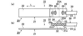
図1(a)は本発明の第1実施形態の電線と端子の接続構造の接続前の端子の平面図、図1(b)は同接続構造の接続前の端子の側面図、図2(a)は同接続構造の端子に電線を配置した状態を示す平面図、図2(b)は同接続構造の端子に電線を配置した状態を示す側面図、図3(a)は同接続構造の端子に電線を接続した状態を示す平面図、図3(b)は同接続構造の端子に電線を接続した状態を示す側面図である。 FIG. 1A is a plan view of a terminal before connection in a connection structure between an electric wire and a terminal according to a first embodiment of the present invention, FIG. 1B is a side view of the terminal before connection in the connection structure, and FIG. 2A is a plan view showing a state where electric wires are arranged on the terminals of the connection structure, FIG. 2B is a side view showing a state where electric wires are arranged on the terminals of the connection structure, and FIG. 3B is a plan view showing a state where an electric wire is connected to the terminal, and FIG. 3B is a side view showing a state where the electric wire is connected to the terminal having the same connection structure.
図2(a),(b)及び図3(a),(b)に示すように、電線と端子の接続構造10は、導電性の底板(ベース板)21の折り返し部23から該底板21の長手方向Lに電線挿通孔28を有する傾斜した第1と第2の一対の弾性接続片(バネ片)25,26を折り曲げ形成した端子20と、絶縁被覆31から露出した素線が極細の芯線32を有する電線30と、を備え、一対の弾性接続片25,26の各電線挿通孔28に電線30の絶縁被覆31から露出した素線が極細の芯線32を挿通させ、山状に相対向して傾斜した一対の弾性接続片25,26に圧力を加えて平坦面状に潰して底板21の上面21aに芯線32を接続するものである。
As shown in FIGS. 2 (a) and 2 (b) and FIGS. 3 (a) and 3 (b), the
図1(a),(b)及び図2(a),(b)に示すように、端子20の底板21は、金属製で矩形板状に形成してあり、その前側に図示しない相手端子が接続される端子接続部22を有している。また、底板21の基端側の折り返し部23から所定角度で傾斜した第1の弾性接続片25と第2の弾性接続片26を山状になって相対向するように折り曲げ形成してある。この一対の弾性接続片25,26の中央には、丸形の電線挿通孔28をそれぞれ形成してある。
As shown in FIGS. 1 (a) and 1 (b) and FIGS. 2 (a) and 2 (b), the
そして、図3(a),(b)に示すように、底板21の山状に相対向して傾斜した一対の弾性接続片25,26の各電線挿通孔28に、電線30の絶縁被覆31から露出した芯線32を挿通させた状態で、山状に相対向して傾斜した一対の弾性接続片25,26の頂上部25Aを加圧して、底板21の上面21aと圧潰された(圧力を加えて平面状に潰された)各弾性接続片25′,26′間で電線30の絶縁被覆31から露出した芯線32を挟持して接続するようになっている。
Then, as shown in FIGS. 3A and 3B, the
尚、第2の弾性接続片26の先端には、底板21の上面21aと平行なストレート部26aを折り曲げ形成してあり、山状に相対向して傾斜した一対の弾性接続片25,26の頂上部25Aを加圧した際に、圧力を加えて平面状に潰された一対の弾性接続片25′,26′とストレート部26aとが平坦面状になるようになっている。
A
以上第1実施形態の電線と端子の接続構造10によれば、端子20の山状に相対向して傾斜した一対の弾性接続片25,26の各電線挿通孔28に、電線30の絶縁被覆31から露出した芯線32を挿通させた状態で、山状に相対向して傾斜した一対の弾性接続片25,26の頂上部25Aを加圧して、底板21の上面21aと平坦状に圧潰された各弾性接続片25′,26′間で電線30の絶縁被覆31から露出した芯線32を挟持して接続するようにしたことにより、電線30の素線が極細の芯線32を断線させることなく、端子20と電線30を簡単かつ確実に接続することができる。
As described above, according to the
また、1枚の金属板である底板21に2つの電線挿通孔28を開け、この各電線挿通孔28が山の斜面に位置するように第1の弾性接続片25と第2の弾性接続片26を折り曲げ形成し、この各弾性接続片25,26の電線挿通孔28に電線30の絶縁被覆31から露出した芯線32を挿通させて、山状に相対向して傾斜した各弾性接続片25,26を圧潰させるだけであり、従来の圧着接続のように、クリンパやアンビル等から成る加締め金型の寸法に、端子20と電線30の接続品が制限されてしまうことがないため、狭ピッチのコネクタに対応することができる。また、加圧部品の共用も可能となるため、その分低コスト化を図ることができる。
Further, two electric
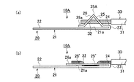
図4(a)は本発明の第2実施形態の電線と端子の接続構造の接続前の端子の平面図、図4(b)は同接続構造の接続前の端子の側面図、図5(a)は同接続構造の端子に電線を配置した状態を示す側面図、図5(b)は同接続構造の端子に電線を接続した状態を示す側面図である。 FIG. 4A is a plan view of a terminal before connection in a connection structure between an electric wire and a terminal according to a second embodiment of the present invention, FIG. 4B is a side view of the terminal before connection in the connection structure, and FIG. FIG. 5A is a side view showing a state where an electric wire is arranged on a terminal having the same connection structure, and FIG. 5B is a side view showing a state where an electric wire is connected to a terminal having the same connection structure.
この第2実施形態の電線と端子の接続構造10Aは、底板(ベース板)21の折り返し部23と該折り返し部23側に位置する傾斜した第1の弾性接続片25との間にストレート部24を設けた点が、前記第1実施形態のものとは異なる。尚、他の構成は、前記第1実施形態と同様であるため、同一構成部分には同一符号を付して詳細な説明は省略する。
The electric wire and
この第2実施形態の電線と端子の接続構造10Aでは、底板21の折り返し部23と第1の弾性接続片25との間にストレート部24を設けたことにより、山状に相対向して傾斜した一対の弾性接続片25,26の頂上部25Aを加圧して、底板21の上面21aと圧潰された各弾性接続片25′,26′間で電線30の絶縁被覆31から露出した芯線32を挟持して接続する際に、折り返し部23側のストレート部24上と第2の弾性接続片26の先端側のストレート部26a上とに電線30の芯線32を安定した状態で接触させて接続することができ、電線30の素線が極細の芯線32を断線させることなく、底板21の上面21aに端子20と電線30を簡単かつ確実に接続することができる。
In the
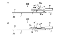
図6(a)は本発明の第3実施形態の電線と端子の接続構造の接続前の端子の平面図、図6(b)は同接続構造の端子に電線を配置した状態を示す側面図、図7(a)は同接続構造の端子に電線を配置した状態を示す側面図、図7(b)は同接続構造の端子に電線を接続した状態を示す側面図である。 FIG. 6A is a plan view of a terminal before connection in a connection structure between an electric wire and a terminal according to a third embodiment of the present invention, and FIG. 6B is a side view showing a state where the electric wire is arranged in the terminal of the connection structure. FIG. 7A is a side view showing a state in which an electric wire is arranged on a terminal having the same connection structure, and FIG. 7B is a side view showing a state in which an electric wire is connected to a terminal having the same connection structure.
この第3実施形態の電線と端子の接続構造10Bは、底板(ベース板)21の山状に相対向して傾斜した一対の弾性接続片25,26の各電線挿通孔28′を底板21の幅方向Hから互い違い開放されて貫通する長孔形状に形成した点が、前記第1実施形態のものとは異なる。尚、他の構成は、前記第1実施形態と同様であるため、同一構成部分には同一符号を付して詳細な説明は省略する。
The
この第3実施形態の電線と端子の接続構造10Bでは、底板21の幅方向Hから互い違い開放されて貫通する山状に相対向して傾斜した一対の弾性接続片25,26の各電線挿通孔28′に電線30の絶縁被覆31から露出した芯線32を簡単かつ確実に挿通させることができ、電線30の素線が極細の芯線32を断線させることなく、底板21の上面21aに端子20と電線30を簡単かつ確実に接続することができる。
In the
図8(a)は本発明の第4実施形態の電線と端子の接続構造の接続前の端子の平面図、図8(b)は同接続構造の接続前の端子の側面図、図9(a)は同接続構造の端子に電線を配置した状態を示す平面図、図9(b)は同接続構造の端子に電線を接続した状態を示す側面図である。 FIG. 8A is a plan view of a terminal before connection in a connection structure between an electric wire and a terminal according to a fourth embodiment of the present invention, FIG. 8B is a side view of the terminal before connection in the connection structure, and FIG. FIG. 9A is a plan view showing a state where electric wires are arranged on the terminals of the connection structure, and FIG. 9B is a side view showing a state where electric wires are connected to the terminals of the connection structure.
この第4実施形態の電線と端子の接続構造10Cは、底板(ベース板)21の山状に相対向して傾斜した一対の弾性接続片25,26の折り返し部23と反対側に位置する傾斜した第2の弾性接続片26の頂下端26B側に折り返し部23側に位置する第1の弾性接続片25と同じ角度で傾斜する第3の弾性接続片27を更に折り曲げ形成して、山状に相対向して傾斜した一対の弾性接続片25,26の頂上部25Aを加圧した際に、底板21と圧潰された第3の弾性接続片27′間で電線30の絶縁被覆31から露出した芯線32の先端32a側を挟持して接続させた点が、前記第1実施形態のものとは異なる。尚、他の構成は、前記第1実施形態と同様であるため、同一構成部分には同一符号を付して詳細な説明は省略する。
The electric wire and
即ち、この第4実施形態の電線と端子の接続構造10Cでは、山状に相対向して傾斜した一対の弾性接続片25,26の頂上部25Aを加圧する際に、第2の弾性接続片26の頂下端26Bから折り曲げ形成された弾性接続片27も平坦状に圧潰され、この圧潰された第3の弾性接続片27′と底板21と間で電線30の絶縁被覆31から露出した芯線32の先端32a側を挟持して接続するため、芯線32の先端32a側の跳ね上がりを確実に防止することができる。
That is, in the
図10(a)〜(d)は本発明の端子の電線の芯線との接続部分の変形例を示す部分平面図、図10(a′)〜(d′)は図10(a)〜(d)の断面図である。 10 (a) to 10 (d) are partial plan views showing modified examples of the connection portion of the terminal of the present invention with the core of the electric wire, and FIGS. 10 (a ') to 10 (d') are diagrams of FIGS. It is sectional drawing of d).
前記第1実施形態から第4実施形態に用いられる端子20の底板21の各弾性接続片に対向する上面21aは、フラットな平面に形成されているが、図10(a)〜(d)及び図10(a′)〜(d′)に示すように、底板(ベース板)21の電線30の絶縁被覆31から露出した芯線32と接触する箇所にセレーション(凹凸形状)29を設けても良い。
The
即ち、図10(a),(a′)に示すように、底板21の中央に3つの凹部29aを平行に形成したり、また、図10(b),(b′)に示すように、底板21の中央に両側まで貫通する3つの溝状凹部29bを形成したり、また、図10(c),(c′)に示すように、底板21の中央に2つの凸部29cとその間に1つの凹部29aを形成したり、さらに、図10(d),(d′)に示すように、底板21の中央に2つの凸部29cとその間に複数の丸形凹部29dを形成しても良い。
That is, as shown in FIGS. 10 (a) and (a '), three
尚、前記各実施形態において、電線挿通孔を有した弾性接続片を4つ以上折り曲げ形成しても良い。 In each of the above embodiments, four or more elastic connection pieces having electric wire insertion holes may be formed by bending.
10,10A,10B,10C 電線と端子の接続構造
20 端子
21 底板(ベース板)
23 折り返し部
24 ストレート部
25,26 第1と第2の一対の弾性接続片
25′,26′圧潰された一対の弾性接続片
25A 頂上部
26B 頂下端
27 第3の弾性接続片
27′圧潰された第3の弾性接続片
28 電線挿通孔
30 電線
31 絶縁被覆
32 芯線
L 底板の長手方向
H 底板の幅方向
10, 10A, 10B, 10C Wire and
23 Folded
Claims (5)
前記傾斜した弾性接続片の電線挿通孔に前記電線の絶縁被覆から露出した芯線を挿通させて前記端子に前記電線を接続する電線と端子の接続構造であって、
前記ベース板の折り返し部から前記傾斜した弾性接続片を山状に相対向させて傾斜するように少なくとも一対設け、
前記山状に相対向して傾斜した少なくとも一対の弾性接続片の各電線挿通孔に、前記電線の絶縁被覆から露出した芯線を挿通させた状態で、前記山状に相対向して傾斜した少なくとも一対の弾性接続片の頂上部を加圧して、前記ベース板と圧潰された前記各弾性接続片間で前記電線の絶縁被覆から露出した芯線を挟持して接続させたことを特徴とする電線と端子の接続構造。 A terminal having a bent elastic connection piece having an electric wire insertion hole in a longitudinal direction of the base plate from a folded portion of the base plate, and an electric wire having a core wire exposed from the insulating coating,
A wire and terminal connection structure for connecting the wire to the terminal by inserting a core exposed from the insulating coating of the wire into the wire insertion hole of the inclined elastic connection piece,
At least one pair is provided so that the inclined elastic connection pieces are opposed to each other in a mountain shape and inclined from the folded portion of the base plate,
In a state where the core wire exposed from the insulating coating of the electric wire is inserted into each of the wire insertion holes of at least one pair of elastic connection pieces inclined to face each other in the shape of the mountain, at least the face inclined to the shape of the mountain is at least inclined. By pressing the tops of the pair of elastic connection pieces, the base plate and the crushed elastic connection pieces sandwiched between the core wires exposed from the insulating coating of the wires and connected to the wire. Terminal connection structure.
前記山状に相対向して傾斜した一対の弾性接続片の前記折り返し部と反対側に位置する傾斜した弾性接続片の頂下端側に前記折り返し部側に位置する弾性接続片と同じ角度で傾斜する第3の弾性接続片を更に折り曲げ形成して、前記山状に相対向して傾斜した少なくとも一対の弾性接続片の頂上部を加圧した際に、前記ベース板と圧潰された前記第3の弾性接続片間で前記電線の絶縁被覆から露出した芯線の先端側を挟持して接続させたことを特徴とする電線と端子の接続構造。 It is a connection structure of the electric wire and terminal of Claim 1, Comprising:
The pair of elastic connection pieces that are inclined opposite to each other in the shape of a mountain are inclined at the same angle as the elastic connection pieces located on the side of the folded part at the top and lower ends of the inclined elastic connection pieces located on the opposite side to the folded part. The third elastic connecting piece is further bent and formed, and when the tops of at least a pair of elastic connecting pieces inclined opposite to each other in a mountain shape are pressed, the third plate crushed with the base plate. Characterized in that the distal end side of the core wire exposed from the insulating coating of the electric wire is sandwiched and connected between the elastic connection pieces of the electric wire and the terminal.
前記山状に相対向して傾斜した少なくとも一対の弾性接続片の各電線挿通孔を前記ベース板の幅方向から開放されて貫通する長孔形状に形成したことを特徴とする電線と端子の接続構造。 It is a connection structure of the electric wire and terminal of Claim 1, Comprising:
A connection between an electric wire and a terminal, wherein each of the electric wire insertion holes of at least one pair of elastic connection pieces inclined to face each other in the shape of a mountain is formed in a long hole shape which is opened from the width direction of the base plate and penetrates. Construction.
前記ベース板の前記電線の絶縁被覆から露出した芯線と接触する箇所に凹凸形状を設けたことを特徴とする電線と端子の接続構造。 It is a connection structure of an electric wire and a terminal according to any one of claims 1 to 3,
A connection structure between an electric wire and a terminal, wherein an uneven shape is provided at a portion of the base plate which comes into contact with a core wire exposed from an insulating coating of the electric wire.
前記ベース板の折り返し部と該折り返し部側に位置する傾斜した弾性接続片との間にストレート部を設けたことを特徴とする電線と端子の接続構造。 It is a connection structure of the electric wire and the terminal according to any one of claims 1 to 4,
A connection structure between an electric wire and a terminal, wherein a straight portion is provided between a folded portion of the base plate and an inclined elastic connecting piece located on the folded portion side.
Priority Applications (2)
| Application Number | Priority Date | Filing Date | Title |
|---|---|---|---|
| JP2018128696A JP6796621B2 (en) | 2018-07-06 | 2018-07-06 | Terminals used in the method of manufacturing the connection structure between electric wires and terminals and the method of manufacturing the connection structure between electric wires and terminals |
| US16/460,370 US10637162B2 (en) | 2018-07-06 | 2019-07-02 | Connection structure of the electric-wire and the terminal |
Applications Claiming Priority (1)
| Application Number | Priority Date | Filing Date | Title |
|---|---|---|---|
| JP2018128696A JP6796621B2 (en) | 2018-07-06 | 2018-07-06 | Terminals used in the method of manufacturing the connection structure between electric wires and terminals and the method of manufacturing the connection structure between electric wires and terminals |
Publications (2)
| Publication Number | Publication Date |
|---|---|
| JP2020009600A true JP2020009600A (en) | 2020-01-16 |
| JP6796621B2 JP6796621B2 (en) | 2020-12-09 |
Family
ID=69102475
Family Applications (1)
| Application Number | Title | Priority Date | Filing Date |
|---|---|---|---|
| JP2018128696A Active JP6796621B2 (en) | 2018-07-06 | 2018-07-06 | Terminals used in the method of manufacturing the connection structure between electric wires and terminals and the method of manufacturing the connection structure between electric wires and terminals |
Country Status (2)
| Country | Link |
|---|---|
| US (1) | US10637162B2 (en) |
| JP (1) | JP6796621B2 (en) |
Cited By (1)
| Publication number | Priority date | Publication date | Assignee | Title |
|---|---|---|---|---|
| KR20210094879A (en) * | 2020-01-22 | 2021-07-30 | 엘에스엠트론 주식회사 | Flexible flat cable busbar |
Citations (3)
| Publication number | Priority date | Publication date | Assignee | Title |
|---|---|---|---|---|
| JPS4817681U (en) * | 1971-07-06 | 1973-02-28 | ||
| JPS501424Y1 (en) * | 1970-01-30 | 1975-01-16 | ||
| JPS5577833U (en) * | 1978-11-21 | 1980-05-29 |
Family Cites Families (27)
| Publication number | Priority date | Publication date | Assignee | Title |
|---|---|---|---|---|
| US3594704A (en) * | 1969-10-02 | 1971-07-20 | Raychem Corp | In-line connector for electrical conductors or the like |
| US3697926A (en) * | 1970-07-23 | 1972-10-10 | Molex Products Co | Plural circuit board connecting arrangement and terminal therefor |
| GB1438657A (en) * | 1972-08-23 | 1976-06-09 | Post Office | Electrical connectors |
| US3852702A (en) * | 1973-07-27 | 1974-12-03 | Amp Inc | Electrical terminal having pyramid teeth thereon |
| US4560224A (en) * | 1982-01-15 | 1985-12-24 | Amp Incorporated | Flat cable termination |
| JPS5937859U (en) * | 1982-08-30 | 1984-03-09 | マブチモ−タ−株式会社 | brush device |
| US4555155A (en) * | 1983-11-28 | 1985-11-26 | Minnesota Mining And Manufacturing Company | Bioelectrode connector |
| US4875876A (en) * | 1988-08-31 | 1989-10-24 | Thomas & Betts Corporation | Electrical connector for overlapped conductors |
| US4948382A (en) * | 1988-12-06 | 1990-08-14 | Amp Incorporated | Miniature insulation displacement electrical contact |
| US5864090A (en) * | 1997-09-03 | 1999-01-26 | Osram Sylvania Inc. | Ground device and method of grounding a cable using same |
| JP2000260504A (en) * | 1999-03-11 | 2000-09-22 | Jst Mfg Co Ltd | FPC crimping terminal and core wire crimping structure using the same |
| JP3775557B2 (en) * | 1999-11-04 | 2006-05-17 | 住友電装株式会社 | connector |
| JP4668687B2 (en) * | 2005-05-27 | 2011-04-13 | 矢崎総業株式会社 | Piercing terminal, connection structure between flat circuit body and piercing terminal, and connection method between flat circuit body and piercing terminal |
| JP4520929B2 (en) * | 2005-10-25 | 2010-08-11 | 矢崎総業株式会社 | Terminal fitting and mounting method |
| JP4568210B2 (en) * | 2005-11-14 | 2010-10-27 | 矢崎総業株式会社 | Terminal metal fittings and flat circuit body with terminals |
| CA2573845C (en) * | 2006-04-20 | 2009-11-24 | Thomas & Betts International, Inc. | Electrical connector components |
| US7650914B2 (en) * | 2006-06-22 | 2010-01-26 | Autosplice, Inc. | Apparatus and methods for filament crimping and manufacturing |
| JP4728986B2 (en) | 2007-03-13 | 2011-07-20 | 古河電気工業株式会社 | Terminal crimping structure for ultra-fine wires for automobiles |
| EP2124295A3 (en) * | 2008-05-24 | 2011-03-30 | Lumberg Connect GmbH | Electrical contact |
| US7618279B1 (en) * | 2008-06-26 | 2009-11-17 | Thomas & Betts International, Inc. | One-piece push-in electrical contact terminal |
| JP5175897B2 (en) * | 2010-05-12 | 2013-04-03 | トヨタ自動車株式会社 | Electrical cable and electrical connector |
| BRPI1104452A2 (en) * | 2010-09-07 | 2014-01-14 | Framatome Connectors Int | ELECTRIC TERMINAL AND ELECTRICAL CONNECTOR ASSEMBLY |
| US20120309225A1 (en) * | 2011-06-01 | 2012-12-06 | Motomu Kajiura | Electrical connector having crimp-mounted electrical terminals |
| US9054430B2 (en) * | 2012-07-02 | 2015-06-09 | Yazaki Corporation | Connection terminal |
| JP2014044844A (en) * | 2012-08-27 | 2014-03-13 | Yazaki Corp | Conductor connection structure |
| US9935382B2 (en) * | 2012-12-17 | 2018-04-03 | Panasonic Intellectual Property Management Co., Ltd. | Connector, contact used in connector, housing, wired housing, and method for manufacturing wired housing |
| US9960504B2 (en) * | 2016-01-12 | 2018-05-01 | Yazaki Corporation | Shielded connector |
-
2018
- 2018-07-06 JP JP2018128696A patent/JP6796621B2/en active Active
-
2019
- 2019-07-02 US US16/460,370 patent/US10637162B2/en active Active
Patent Citations (3)
| Publication number | Priority date | Publication date | Assignee | Title |
|---|---|---|---|---|
| JPS501424Y1 (en) * | 1970-01-30 | 1975-01-16 | ||
| JPS4817681U (en) * | 1971-07-06 | 1973-02-28 | ||
| JPS5577833U (en) * | 1978-11-21 | 1980-05-29 |
Cited By (2)
| Publication number | Priority date | Publication date | Assignee | Title |
|---|---|---|---|---|
| KR20210094879A (en) * | 2020-01-22 | 2021-07-30 | 엘에스엠트론 주식회사 | Flexible flat cable busbar |
| KR102783312B1 (en) * | 2020-01-22 | 2025-03-17 | 엘에스엠트론 주식회사 | Flexible flat cable busbar |
Also Published As
| Publication number | Publication date |
|---|---|
| JP6796621B2 (en) | 2020-12-09 |
| US20200014125A1 (en) | 2020-01-09 |
| US10637162B2 (en) | 2020-04-28 |
Similar Documents
| Publication | Publication Date | Title |
|---|---|---|
| CN101569062B (en) | Connector | |
| US20100087105A1 (en) | Electrical connection system for use on aluminum wires | |
| US6447345B2 (en) | Receptacle terminal | |
| US20070270020A1 (en) | Electrical contact with stapled connection | |
| WO2011111138A1 (en) | Connecting structure of aluminum conductor and connector | |
| JP6011032B2 (en) | Pressure contact terminal | |
| JP2009245695A (en) | Crimp terminal | |
| JP2009259558A (en) | Crimping connection structure | |
| JP7102134B2 (en) | connector | |
| JP2005135757A (en) | Male terminal and male connector using the same | |
| JP6085709B2 (en) | Female terminal structure | |
| US10637162B2 (en) | Connection structure of the electric-wire and the terminal | |
| CN101373864A (en) | Low thickness USB plug connector and USB connector using the same | |
| JP2010010072A (en) | Contact carrier | |
| TWI569544B (en) | Wire connector | |
| JP2013118102A (en) | Female terminal structure | |
| JP6796619B2 (en) | Connection structure of electric wire and terminal | |
| JP2007059304A (en) | Electric wire with terminal and manufacturing method thereof | |
| JP2020004519A (en) | Connection structure of electric wire and terminal | |
| KR20010085190A (en) | Terminal connector and method of manufacturing the same | |
| JP5665533B2 (en) | Connector assembly | |
| JP2012038488A (en) | Crimp terminal | |
| JPH0621184Y2 (en) | Insulation displacement connector | |
| JP5074983B2 (en) | Crimp terminal | |
| KR100814926B1 (en) | Splice Terminal |
Legal Events
| Date | Code | Title | Description |
|---|---|---|---|
| A621 | Written request for application examination |
Free format text: JAPANESE INTERMEDIATE CODE: A621 Effective date: 20190919 |
|
| A977 | Report on retrieval |
Free format text: JAPANESE INTERMEDIATE CODE: A971007 Effective date: 20200717 |
|
| A131 | Notification of reasons for refusal |
Free format text: JAPANESE INTERMEDIATE CODE: A131 Effective date: 20200728 |
|
| A521 | Request for written amendment filed |
Free format text: JAPANESE INTERMEDIATE CODE: A523 Effective date: 20200923 |
|
| TRDD | Decision of grant or rejection written | ||
| A01 | Written decision to grant a patent or to grant a registration (utility model) |
Free format text: JAPANESE INTERMEDIATE CODE: A01 Effective date: 20201104 |
|
| A61 | First payment of annual fees (during grant procedure) |
Free format text: JAPANESE INTERMEDIATE CODE: A61 Effective date: 20201116 |
|
| R150 | Certificate of patent or registration of utility model |
Ref document number: 6796621 Country of ref document: JP Free format text: JAPANESE INTERMEDIATE CODE: R150 |
|
| S531 | Written request for registration of change of domicile |
Free format text: JAPANESE INTERMEDIATE CODE: R313531 |
|
| R350 | Written notification of registration of transfer |
Free format text: JAPANESE INTERMEDIATE CODE: R350 |
|
| R250 | Receipt of annual fees |
Free format text: JAPANESE INTERMEDIATE CODE: R250 |
|
| R250 | Receipt of annual fees |
Free format text: JAPANESE INTERMEDIATE CODE: R250 |
|
| R250 | Receipt of annual fees |
Free format text: JAPANESE INTERMEDIATE CODE: R250 |