JP2020009603A - Induction heating apparatus - Google Patents
Induction heating apparatus Download PDFInfo
- Publication number
- JP2020009603A JP2020009603A JP2018128861A JP2018128861A JP2020009603A JP 2020009603 A JP2020009603 A JP 2020009603A JP 2018128861 A JP2018128861 A JP 2018128861A JP 2018128861 A JP2018128861 A JP 2018128861A JP 2020009603 A JP2020009603 A JP 2020009603A
- Authority
- JP
- Japan
- Prior art keywords
- flange
- coil
- arm
- induction heating
- temperature
- Prior art date
- Legal status (The legal status is an assumption and is not a legal conclusion. Google has not performed a legal analysis and makes no representation as to the accuracy of the status listed.)
- Pending
Links
Images









Landscapes
- General Induction Heating (AREA)
Abstract
Description
本発明は、誘導加熱装置に関する。 The present invention relates to an induction heating device.
金属体を焼き戻す装置として、コイルを用いて金属体を加熱する装置が知られている。
例えば、特許文献1には、R部を形成される金属体の周囲に配置された環状のコイルを用いて金属体を加熱する装置が開示されている。特許文献1に開示されている技術では、R部の外側を形成する縁部におけるコイルの移動量を、R部の内側を形成する縁部におけるコイルの移動量に比較して、小さく設定し、R部の外側を形成する縁部の温度をR部の内側を形成する縁部の温度よりも高めている。
As an apparatus for tempering a metal body, an apparatus for heating a metal body using a coil is known.
For example,
ところで、金属体にR部を有するフランジを設けることがある。R部を有するフランジを焼き戻す際には、例えば、フランジを挟み込むように設けられた一対の突出部を有するコイルを用いてフランジを加熱する。しかしながら、一対の突出部を有するコイルを用いてR部を有するフランジを焼き戻す場合、以下の問題が発生する。以下、図17及び図18を参照して、本発明の課題について説明する。 Incidentally, a metal body may be provided with a flange having an R portion. When tempering the flange having the R portion, the flange is heated using, for example, a coil having a pair of protrusions provided so as to sandwich the flange. However, when tempering a flange having an R portion using a coil having a pair of projecting portions, the following problem occurs. Hereinafter, the problem of the present invention will be described with reference to FIGS.
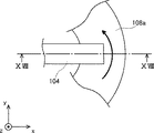
図17は、一対の突出部を有するコイルの平面図である。コイル104は、フランジ108を加熱する。図17に示すように、フランジ108は、R部を有する。図18は、図15のXVIII−XVIII線に沿う断面図である。図18に示すように、コイル104は、フランジ108を挟み込むように設けられた一対の突出部104aを有する。図17に示す矢印は、コイル104の送り方向を示す。
FIG. 17 is a plan view of a coil having a pair of protrusions. The
コイル104は、図示しないアームを用いて操作される。図示しないアームは、コイル104の軌跡が円弧となるようにコイル104を操作する。したがって、R部の外側におけるコイル104の単位時間当りの移動量は、R部の内側におけるコイル104の単位時間当りの移動量に比較して、大きい。そのため、R部の外側部は、R部の内側部に比較して、温度が上昇しやすい。したがって、R部の内側部及びR部の外側部において、温度差が発生する。つまり、フランジの幅方向において、温度ムラが発生する。
The
本発明は、このような課題に鑑みなされたものであり、フランジの幅方向における温度ムラの発生を抑制しつつ、R部を有するフランジを加熱可能な誘導加熱装置を提供することを目的とする。 The present invention has been made in view of such problems, and has as its object to provide an induction heating device capable of heating a flange having an R portion while suppressing the occurrence of temperature unevenness in the width direction of the flange. .
上記目的を達成する一態様は、端部にコイルが接続されたアームと、前記アームを操作するアーム制御部と、を備え、R部を有するフランジの表面に、前記コイルが沿うように前記アームを操作し、前記コイルを用いて前記フランジを加熱する誘導加熱装置であって、前記コイルの先端部には、磁性体である磁性コアが接続され、前記アーム制御部は、前記磁性コアを前記フランジの縁部よりも前記フランジの根元側に配置した状態、かつ、前記R部の内側から前記R部の外側に向かって、前記コイルが前記フランジに近づくように傾斜させた状態で、前記コイルが前記R部に沿うように前記アームを操作する。 One embodiment for achieving the above object includes an arm having a coil connected to an end thereof, and an arm control unit for operating the arm, wherein the arm is arranged so that the coil is along a surface of a flange having an R portion. Is an induction heating device that heats the flange by using the coil, wherein a magnetic core that is a magnetic material is connected to a distal end of the coil, and the arm control unit controls the magnetic core to In a state where the coil is inclined from the inside of the R portion to the outside of the R portion so as to be closer to the flange, the coil is disposed in a state where the coil is disposed closer to the base of the flange than an edge of the flange. Operates the arm so as to follow the R portion.
本発明に係る誘導加熱装置は、コイルの先端部が、磁性体である磁性コアが接続され、アーム制御部が、磁性コアをフランジの縁部よりもフランジの根元側に配置した状態で、コイルがR部に沿うようにアームを操作する。そのため、フランジの根元側を通過する磁束が増加する。したがって、フランジの縁部が過熱されにくい。 In the induction heating device according to the present invention, the tip of the coil is connected to a magnetic core, which is a magnetic material, and the arm control unit arranges the magnetic core closer to the base of the flange than the edge of the flange. Operate the arm so that it follows the R section. Therefore, the magnetic flux passing through the root of the flange increases. Therefore, the edge of the flange is less likely to be overheated.
さらに、本発明に係る誘導加熱装置は、アーム制御部が、前記R部の内側から前記R部の外側に向かって、前記コイルが前記フランジに近づくように傾斜させた状態で、前記コイルが前記R部に沿うように前記アームを操作する。つまり、R部の内側部におけるフランジの誘導加熱が抑制される。そのため、フランジの幅方向における温度ムラの発生を抑制しつつ、R部を有するフランジを加熱することができる。 Further, in the induction heating device according to the present invention, in a state where the arm control section is inclined from the inside of the R section to the outside of the R section so that the coil approaches the flange, The arm is operated so as to follow the R section. That is, induction heating of the flange in the inner portion of the R portion is suppressed. Therefore, the flange having the R portion can be heated while suppressing the occurrence of temperature unevenness in the width direction of the flange.
以下、本発明を適用した具体的な実施の形態について、図面を参照しながら詳細に説明する。ただし、本発明が以下の実施の形態に限定される訳ではない。また、説明を明確にするため、以下の記載及び図面は、適宜、簡略化されている。 Hereinafter, specific embodiments to which the present invention is applied will be described in detail with reference to the drawings. However, the present invention is not limited to the following embodiments. In addition, in order to clarify the description, the following description and drawings are simplified as appropriate.
まず、図1及び図2を参照して、本実施の形態に係る誘導加熱装置の構成について説明する。図1は、本実施の形態に係る誘導加熱装置の全体図である。図2は、金属体の斜視図である。図1に示すように、誘導加熱装置1は、アーム2、コイル4、磁性コア5、変位計6a、アーム制御部6b、温度計7a、温調器7b、及び発振器7cを備える。なお、図1には、フランジ8aも図示している。図2に示す金属体8は、フランジ8aを有する。なお、図1における矢印は、コイル4の送り方向を示す。
First, the configuration of the induction heating device according to the present embodiment will be described with reference to FIGS. FIG. 1 is an overall view of an induction heating device according to the present embodiment. FIG. 2 is a perspective view of the metal body. As shown in FIG. 1, the
アーム2は、アーム制御部6bを用いて操作される。アーム2の端部には、コイル4が接続されている。アーム制御部6bは、アーム2を操作することによって、コイル4の配置を3次元的に制御することができる。例えば、図1に示すように、アーム制御部6bは、コイル4がフランジ8aに沿うように、アーム2を操作することができる。
The
図2に示すように、フランジ8aは、金属体8に設けられている。金属体8は、フランジ8aを用いて他の金属部材等に連結される。フランジ8aが設けられる位置は、特に限定されない。フランジ8aは、金属体8の縁部に設けられてもよいし、金属体8の途中部に設けられてもよい。金属体8の形状は特に限定されない。金属体8は、例えば、筒状部材等であってもよい。
As shown in FIG. 2, the
図2に示す例では、金属体8は、溝部8bを有する形状である。具体的には、金属体8は、板部8c、側壁8d、及び側壁8eを有する。側壁8d及び側壁8eは、板部8cの対向する縁部に、板部8cに垂直な方向にそれぞれ接続されている。板部8c、側壁8d、及び側壁8eは、溝部8bを形成する。側壁8dの板部8cに接続されている端に対向する端には、フランジ8aが設けられている。側壁8eの対面に接続されている端に対向する端には、フランジ8fが設けられている。フランジ8a及びフランジ8fは、板部8cに平行な方向に設けられている。
In the example shown in FIG. 2, the metal body 8 has a shape having a
フランジ8aは、図2に示す地点Oを中心とするR部81aを有する。フランジ8aは、R部81aに加えて図8に図示する直線部82aを有していてもよい。フランジ8aは、金属材料等の電気伝導率が高い材料を用いて形成される。フランジ8aは、例えば鉄合金を用いて形成される。フランジ8aは、金属体8と同一の金属材料を用いて形成されてもよいし、異なる金属材料を用いて形成されてもよい。
The
以下、コイル4を用いてフランジ8aを誘導加熱する場合について説明する。なお、フランジ8fは、フランジ8aと同様にコイル4を用いて誘導加熱される。フランジ8aと側壁8dとが接合している辺の近傍を、フランジ8aの根元側とする。また、フランジ8aの根元側に対向する辺の近傍を、フランジ8aの縁部側とする。フランジ8aの根元側からフランジ8aの縁部側に向かう方向を幅方向とする。
Hereinafter, a case where the
コイル4は、発振器7cに接続されている。発振器7cは、コイル4に交流電流を流すことができる。コイル4は、例えば、断面矩形状の金属角線をU字状に折り曲げて形成される。コイル4は、例えば、銅や銅合金を用いて形成される。電流が流されているコイル4の周囲には、磁束が生じる。コイル4の周囲に磁束が生じた状態でコイル4がフランジ8aに沿うようにアーム2を操作すると、フランジ8aに渦電流が発生する。渦電流が発生すると、フランジ8aは発熱する。このようにフランジ8aは、コイル4を用いて誘導加熱される。
The
コイル4の先端部には、磁性コア5が接続されている。磁性コア5は、磁性体を用いて形成される。磁性コア5を形成する磁性体は、周辺の空気の比透磁率(≒1.0)に対し十分に透磁率が高く、かつ、自身が誘導加熱されないように十分高い電気抵抗を有する。磁性コア5は、例えばフランジ8aに比較して、電気抵抗が高い。したがって、磁性コア5は、フランジ8aに比較して、コイル4に交流電流を流しても渦電流が発生しにくい。そのため、磁性コア5は、フランジ8aに比較して、発熱しにくい。また、フランジ8aの磁性コア5直下は、磁性コア5が配置されていない部分に比較して、周辺の漏れ磁束が集中するため、磁束密度が高くなり、発熱されやすい。磁性コア5は、例えば、フェライトを用いて形成される。
A
コイル4は、フランジ8aに対向する面が露出している。つまり、磁性コア5は、コイル4のフランジ8aに対向する面が露出するように配置される。コイル4のフランジ8aに対向する面が露出するように磁性コア5を配置すると、磁性コア5とフランジ8aとの間隙近傍に磁束が集中する。そのため、磁性コア5が接続されたコイル4を用いると、磁性コア5を配置しない場合に比較して、フランジ8aの誘導加熱が、磁性コア5が配置された近傍において起こりやすい。
The surface of the
コイル4は、アーム2を用いて、図1の矢印に示す送り方向にフランジ8aに沿うように操作される。フランジ8aは、コイル4がフランジ8aに沿うように操作されると、誘導加熱される。フランジ8aは、コイル4を用いて誘導加熱されると、熱膨張する。したがって、コイル4がフランジ8aに沿うようにアーム2を操作すると、コイル4とフランジ8aとのギャップがフランジ8aの熱膨張によって変化する。
The
そこで、変位計6aを用いてコイル4とフランジ8aとのギャップを常時計測する。変位計6aは、例えば、レーザー変位計である。変位計6aは、コイル4と共に移動する。変位計6aは、図1に示す例では、コイル4の送り方向側に配置されている。しかしながら、変位計6aは、コイル4とフランジ8aとのギャップを測定可能であれば、どのような位置に配置されていてもよい。変位計6aは、例えば、磁性コア5よりもフランジ8aの根元側に配置されていてもよい。また、変位計6aは、1つ配置されていてもよいし、複数配置されていてもよい。
Therefore, the gap between the
変位計6aは、アーム制御部6bに接続されている。アーム制御部6bは、アーム2を操作する。アーム制御部6bは、変位計6aにおいて取得されたコイル4の位置情報に基づいて、コイル4の位置を補正する指令をアーム2に出す。このような構成によって、アーム制御部6bは、コイル4の位置を補正しつつ、コイル4がフランジ8aに沿うようにアーム2を操作することができる。
The displacement gauge 6a is connected to the
図1に示すように、コイル4の反送り方向側には、温度計7aが配置されている。温度計7aは、コイル4が通過後のフランジ8aの温度を常時計測する。温度計7aは、例えば、放射温度計である。温度計7aは、コイル4と共に移動する。温度計7aは、温調器7bに接続されている。温調器7bは、温度計7aにおいて取得されたフランジ8aの温度情報に基づいて、発振器7cの出力値を制御する。温調器7bは、PID制御(Proportional−Integral−Differential Controller)を用いて、発振器7cの出力値を制御する。
As shown in FIG. 1, a
温度計7aは、誘導加熱されたフランジ8aの温度を計測することができる位置であれば、どのような位置に配置されていてもよい。また、温度計7aは、1つ配置されていてもよいし、複数配置されていてもよい。例えば、フランジ8aの根元側及びフランジ8aの縁部側に温度計7aを配置すると、フランジ8aの幅方向における温度差を計測することができる。
The
発振器7cは、温調器7bに指令された出力値でコイル4に交流電流を流す。交流電流が流されたコイル4は、フランジ8aを誘導加熱することができる。つまり、誘導加熱装置1は、PID制御を用いたコイル4の温度制御及びコイル4の位置情報に基づくコイル4の位置補正を行いつつ、フランジ8aを誘導加熱する。
The oscillator 7c allows an alternating current to flow through the
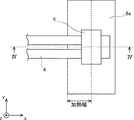
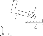
次に、図3〜図5を参照して、コイル4がフランジ8aの直線部82aに沿うようにアーム2を操作する場合について説明する。図3は、フランジの直線部に沿っているコイルの平面図である。図4は、図3のIV−IV線に沿う断面図である。図5は、図4のV−V線に沿う断面図である。なお、図4等では、説明の簡単のため、フランジ8aを、図2に示したフランジ8aと上下反対向きに示している。
Next, a case in which the
なお、当然のことながら、図3及びその他の図面に示した右手系xyz直交座標は、構成要素の位置関係を説明するための便宜的なものである。通常、z軸正方向が鉛直上向き、xy平面が水平面であり、図面間で共通である。 Needless to say, the right-handed xyz rectangular coordinates shown in FIG. 3 and other drawings are for convenience in describing the positional relationship of the components. Usually, the positive direction of the z-axis is vertically upward and the xy plane is the horizontal plane, which is common between the drawings.
図4に示すように、コイル4がフランジ8aの直線部82aに沿うようにアーム2を操作する際には、フランジ8aの縁部よりもフランジ8aの根元側に磁性コア5を配置する。図5に示すように、磁性コア5は、コイル4のフランジ8aに対向する面が露出するように配置されている。
As shown in FIG. 4, when operating the
コイル4がフランジ8aに沿うようにアーム2を操作する際に発生する渦電流は、表皮効果によって、フランジ8aの表面部に集中する。特に、フランジ8aの縁部には、渦電流が集中しやすい。渦電流が集中すると、フランジ8aの縁部は、電磁誘導によって、過熱される虞がある。
The eddy current generated when the
フランジ8aの縁部よりもフランジ8aの根元側に磁性コア5が配置された状態でコイル4がフランジ8aに沿うようにアーム2を操作すると、磁性コア5直下であるフランジ8aの根元側を通過する磁束が増加する。したがって、フランジ8aの根元側における誘導加熱が促進される。つまり、フランジ8aの縁部よりもフランジ8aの根元側に磁性コア5が配置された状態でコイル4がフランジ8aの直線部82aに沿うようにアーム2を操作すると、フランジ8aの縁部の過熱を抑制することができる。
When the
コイル4を用いて誘導加熱すると、図3に示すフランジ8aの加熱幅が加熱される。図3に示すように、コイル4がフランジ8aの直線部82aに沿うようにアーム2を操作する際には、磁性コア5の中心がフランジ8aの加熱幅の根元側端部に位置するように磁性コア5を配置する。磁性コア5の中心がフランジ8aの加熱幅の根元側端部に位置するように磁性コア5が配置された状態でコイル4がフランジ8aに沿うようにアーム2を操作すると、磁性コア5直下であるフランジ8aの根元側を通過する磁束を増加させることができる。したがって、フランジ8aの加熱幅を効率良く誘導加熱することができる。
When induction heating is performed using the
図4に示すように、フランジ8aのz軸正方向側にのみコイル4を配置している。つまり、コイル4は、フランジ8aの片側にのみ配置されている。コイル4がフランジ8aの片側にのみ配置されているため、コイルがフランジを挟み込むように設けられた一対の突出部を有する場合に比較して、フランジ8aの根元側に磁性コア5を配置することができる。したがって、フランジ8aの加熱幅を大きくすることができる。
As shown in FIG. 4, the
さらに、図4に示すように、コイル4がフランジ8aの直線部82aに沿うようにアーム2を操作する際には、コイル4とフランジ8aとを平行に配置する。コイル4とフランジ8aとを平行に配置することによって、コイル4とフランジ8aとのギャップを一定に保つことができる。
Further, as shown in FIG. 4, when operating the
磁性コア5とフランジ8aとのギャップを一定に保った状態でアーム2を操作すると、フランジ8aの縁部側とフランジ8aの根元側とにおける、通過する磁束のばらつきを抑制することができる。したがって、フランジ8aの縁部側とフランジ8aの根元側とにおける誘導加熱のばらつきを抑制することができる。つまり、コイル4とフランジ8aとを平行に配置した状態でコイル4がフランジ8aの直線部82aに沿うようにアーム2を操作すると、フランジ8aの幅方向における温度ムラの発生を抑制しつつフランジ8aの直線部82aを加熱することができる。
When the
次に、図6及び図7を参照して、コイル4がフランジ8aのR部81aに沿うようにアーム2を操作する場合について説明する。図6は、フランジのR部を沿っているコイルの平面図である。図7は、図6のVII−VII線に沿う断面図である。
Next, a case in which the
図6に示すように、コイル4がフランジ8aのR部81aに沿うようにアーム2を操作する際には、フランジ8aの縁部よりもフランジ8aの根元側に磁性コア5を配置する。また、図7に示すように、コイル4がフランジ8aのR部81aに沿うようにアーム2を操作する際には、フランジ8aのR部81aの内側からフランジ8aのR部81aの外側に向かって、コイル4がフランジ8aに近づくように、コイル4を傾斜させる。
As shown in FIG. 6, when operating the
図6に示す矢印は、コイル4の送り方向を示す。アーム2は、コイル4の軌跡がフランジ8aのR部81aの中心を中心とする円弧となるように、操作される。フランジ8aのR部81aの内側におけるコイル4の移動量は、フランジ8aのR部81aの外側におけるコイル4の移動量に比較して、少ない。したがって、フランジ8aのR部81aの内側は、フランジ8aのR部81aの外側に比較して、コイル4を用いた誘導加熱によって温度が上昇しやすい。
The arrow shown in FIG. 6 indicates the feed direction of the
磁性コア5とフランジ8aとのギャップを大きくすると、フランジ8aを通過する磁束が減少する。つまり、磁性コア5とフランジ8aとのギャップが大きいと、フランジ8aは加熱されにくい。したがって、フランジ8aのR部81aの内側からフランジ8aのR部81aの外側に向かって、コイル4がフランジ8aに近づくように、コイル4を傾斜させると、フランジ8aのR部81aの内側における誘導加熱を抑制することができる。このような構成によって、フランジ8aの幅方向における温度ムラの発生を抑制しつつフランジ8aのR部81aを加熱することができる。
When the gap between the
フランジ8aの幅方向における温度差が大きい場合、温度差を考慮して傾斜量を決定することが好ましい。例えば、フランジ8aのR部81aの内側における温度がフランジ8aのR部81aの外側における温度よりも低い場合、フランジ8aの幅方向における温度差がない場合に比較して、傾斜量を小さく設定することが好ましい。また、例えば、フランジ8aの直線部82aにおける根元側の温度がフランジ8aの直線部82aにおける縁部側の温度よりも低い場合、フランジ8aの直線部82aにおける温度差がない場合に比較して、傾斜量を大きく設定することが好ましい。
When the temperature difference in the width direction of the
以下、本発明について実施例を示して具体的に説明する。なお、これらの記載は、本発明を限定するものではない。 Hereinafter, the present invention will be described specifically with reference to examples. Note that these descriptions do not limit the present invention.
[実施例1]
(フランジの寸法)
図8は、実施例1において使用したフランジの平面図である。実施例1で使用したフランジ8aは、直線部82a及びR部81aを有する。図1に示すように、R部81aの内側端における半径は、47.5mmであった。また、フランジ8aの幅は、50mmであった。実施例1では、フランジ8aの加熱幅を16.5mmとした。
[Example 1]
(Flange dimensions)
FIG. 8 is a plan view of the flange used in the first embodiment. The
<コイルがフランジの直線部に沿うようにアームを操作する場合>
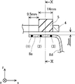
図9は、実施例1においてフランジの直線部に沿っているコイルの断面図である。図10は、図9のX−X線に沿う断面図である。図9に示すように、実施例1においてコイル4がフランジ8aの直線部82aに沿うようにアーム2を操作する場合、磁性コア5とフランジ8aとのギャップは、3mmであった。また、フランジ8aの端部から磁性コア5までの距離は、9.5mmであった。磁性コア5の奥行きは、14mmであった。
<When operating the arm so that the coil runs along the straight part of the flange>
FIG. 9 is a cross-sectional view of the coil along the straight portion of the flange in the first embodiment. FIG. 10 is a sectional view taken along line XX of FIG. As shown in FIG. 9, when the
図10に示すように、コイル4は、断面矩形状の銅製部材であった。磁性コア5は、フランジ8aに対向するコイル4の面が露出するように配置されていた。図10に示すように、磁性コア5の表面からコイル4までの距離(a、c、d)及びコイル4間の距離(b)は、全て6mmであった。
As shown in FIG. 10, the
[比較例1]
上記で説明した誘導加熱装置において、フランジを挟み込むように一対の突出部をコイルに設けた点及び磁性コアを設けない点以外は実施例1と同様とした装置を、比較例1とした。
[Comparative Example 1]
In the induction heating apparatus described above, a comparative example 1 is the same as the example 1 except that a pair of protrusions are provided on the coil so as to sandwich the flange and the magnetic core is not provided.
(温度ムラ測定)
実施例1の誘導加熱装置及び比較例1の誘導加熱装置を用いてフランジ8aの直線部82aを加熱した。図9に示す3つの地点(1)〜(3)におけるフランジ8aの温度を計測した。地点(1)は、フランジ8aの縁部から1mmの地点である。地点(2)は、フランジ8aの縁部から8mmの地点である。地点(3)は、フランジ8aの縁部から16.5mmの地点である。3つの地点(1)〜(3)にそれぞれ熱電対を配置し、フランジ8aの温度を計測した。計測結果を図11に示す。
(Temperature unevenness measurement)
The
図11は、フランジの直線部における温度を示すグラフである。図11に示すように、実施例1の誘導加熱装置では、3つの地点(1)〜(3)のうち、地点(1)が最も高温であった。また、実施例1の誘導加熱装置では、地点(2)が最も低温であった。 FIG. 11 is a graph showing the temperature at the linear portion of the flange. As shown in FIG. 11, in the induction heating device of Example 1, the point (1) had the highest temperature among the three points (1) to (3). In the induction heating device of Example 1, the point (2) had the lowest temperature.
以下、3つの地点(1)〜(3)のうち、最も高温であった地点の温度と最も低温であった地点の温度との差分を、フランジの幅方向における温度ムラと称する。実施例1の誘導加熱装置は、フランジの幅方向における温度ムラが、フランジ8aの直線部82aにおいて、約28℃であった。
Hereinafter, the difference between the temperature of the hottest point and the temperature of the coldest point among the three points (1) to (3) is referred to as temperature unevenness in the width direction of the flange. In the induction heating device of Example 1, the temperature unevenness in the width direction of the flange was about 28 ° C. in the
一方、比較例1の誘導加熱装置では、3つの地点(1)〜(3)のうち、地点(1)が最も高温であった。また、比較例1の誘導加熱装置では、地点(3)が最も低温であった。比較例1の誘導加熱装置は、フランジの幅方向における温度ムラが、フランジの直線部において、約180℃であった。このことから、実施例1は、比較例1に比較して、フランジの幅方向における温度ムラが、フランジ8aの直線部82aにおいて抑制されていることが確認された。
On the other hand, in the induction heating device of Comparative Example 1, the point (1) was the highest temperature among the three points (1) to (3). In the induction heating device of Comparative Example 1, the point (3) had the lowest temperature. In the induction heating device of Comparative Example 1, the temperature unevenness in the width direction of the flange was about 180 ° C. in the straight portion of the flange. From this, it was confirmed that in Example 1, the temperature unevenness in the width direction of the flange was suppressed in the
<コイルがフランジのR部に沿うようにアームを操作する場合>
図12は、実施例1においてフランジのR部に沿っているコイルの断面図である。図12に示すように、実施例1においてコイル4がフランジ8aのR部81aに沿うようにアーム2を操作する際には、コイル4とフランジ8aとのギャップは、フランジ8aの縁部において、6.5mmであった。また、コイル4とフランジ8aとのギャップは、コイル4の先端部において、5mmであった。
<When operating the arm so that the coil is along the R part of the flange>
FIG. 12 is a cross-sectional view of the coil along the R portion of the flange in the first embodiment. As shown in FIG. 12, when operating the
以下、フランジ8aの縁部におけるコイル4とフランジ8aとのギャップと、コイル4の縁部におけるコイル4とフランジ8aとのギャップと、の差分を傾斜量とする。実施例1の誘導加熱装置は、コイル4がフランジ8aのR部81aに沿うようにアーム2を操作する際に、傾斜量が1.5mmであった。
Hereinafter, the difference between the gap between the
図12に示すように、実施例1においてコイル4がフランジ8aのR部81aに沿うようにアーム2を操作する際には、アーム2は、磁性コア5の縁部とフランジ8aの縁部との距離が23.5mmとなるように操作されていた。
As shown in FIG. 12, when operating the
[比較例2]
上記で説明した誘導加熱装置において、コイル4がフランジ8aのR部81aに沿うようにアーム2を操作する際における傾斜量を0mmとした点以外は実施例1と同様とした装置を比較例2とした。
[Comparative Example 2]
In the induction heating device described above, a device which is the same as that of Example 1 except that the amount of inclination when the
(温度ムラ測定)
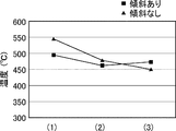
実施例1の誘導加熱装置及び比較例2の誘導加熱装置を用いてフランジ8aのR部81aを加熱した。図12に示す3つの地点(1)〜(3)におけるフランジ8aの温度を計測した。地点(1)は、フランジ8aの縁部から1mmの地点である。地点(2)は、フランジ8aの縁部から8mmの地点である。地点(3)は、フランジ8aの縁部から16.5mmの地点である。地点(1)〜(3)にそれぞれ熱電対を配置し、フランジ8aの温度を計測した。計測結果を図13に示す。
(Temperature unevenness measurement)
The
図13は、フランジのR部における温度を示すグラフである。図13に示すように、実施例1の誘導加熱装置では、3つの地点(1)〜(3)のうち、地点(1)が最も高温であった。また、実施例1の誘導加熱装置では、地点(2)が最も低温であった。実施例1の誘導加熱装置は、フランジの幅方向における温度ムラが、フランジ8aのR部81aにおいて約28℃であった。
FIG. 13 is a graph showing the temperature at the R portion of the flange. As shown in FIG. 13, in the induction heating device of Example 1, the point (1) was the highest temperature among the three points (1) to (3). In the induction heating device of Example 1, the point (2) had the lowest temperature. In the induction heating device of Example 1, the temperature unevenness in the width direction of the flange was about 28 ° C. in the
一方、比較例2の誘導加熱装置では、3つの地点(1)〜(3)のうち、地点(1)が最も高温であった。また、比較例2の誘導加熱装置では、地点(3)が最も低温であった。比較例2の誘導加熱装置は、フランジの幅方向における温度ムラが、フランジ8aのR部81aにおいて約93℃であった。このことから、実施例1は、比較例2に比較して、フランジの幅方向における温度ムラが抑制されていることが確認された。
On the other hand, in the induction heating device of Comparative Example 2, point (1) had the highest temperature among the three points (1) to (3). In the induction heating device of Comparative Example 2, the point (3) was the lowest temperature. In the induction heating device of Comparative Example 2, the temperature unevenness in the width direction of the flange was about 93 ° C. in the
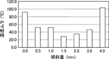
傾斜量を変化させて、コイル4がフランジ8aのR部81aに沿うようにアーム2を操作した場合における、フランジ8aの温度ムラを計測した。計測結果を図14に示す。図14は、フランジのR部81aにおける温度ムラと傾斜量との関係を示すグラフである。図14に示すように、傾斜量が1.5mmである場合に、フランジの幅方向における温度ムラは最も抑制された。
The temperature unevenness of the
(温度制御)
図15は、実施例1において使用したコイルの平面図である。図15に示すように、コイル4の反進行方向側に温度計7aが配置されている。温度計7aとコイル4との距離は、1mmであった。実施例1の誘導加熱装置では、PID制御によって、コイル4の出力を調節している。つまり、実施例1の誘導加熱装置では、コイル4をPID制御しつつ、コイル4とフランジ8aとのギャップを補正している。実施例1におけるPID制御は、以下の条件で行った。
(Temperature control)
FIG. 15 is a plan view of the coil used in the first embodiment. As shown in FIG. 15, a
・PID制御条件
係数KP:75、係数KI:3.0、係数KD:0.6
サンプリング周期:10msec
目標温度:500℃
-PID control conditions Coefficient K P : 75, Coefficient K I : 3.0, Coefficient K D : 0.6
Sampling cycle: 10 msec
Target temperature: 500 ° C
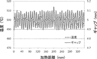
図16は、フランジの温度と加熱距離との関係を示すグラフである。図16におけるフランジの温度は、温度計7aを用いて計測した。図16に示すように、実施例1の誘導加熱装置は、温度変化量が12.6℃であった。また、実施例1の誘導加熱装置は、ギャップ変化量が0.25mmであった。フランジ8aの焼き戻しを行う際には、温度変化量が50℃以下となることが好ましい。つまり、実施例1の誘導加熱装置は、フランジ8aの焼き戻しに好適であることが確認された。
FIG. 16 is a graph showing the relationship between the temperature of the flange and the heating distance. The temperature of the flange in FIG. 16 was measured using the
以上で説明した本実施の形態に係る発明により、フランジの幅方向における温度ムラの発生を抑制しつつ、R部を有するフランジを加熱可能な誘導加熱装置を提供することができる。 According to the invention of the present embodiment described above, it is possible to provide an induction heating device capable of heating a flange having an R portion while suppressing the occurrence of temperature unevenness in the width direction of the flange.
なお、本発明は上記実施の形態に限られたものではなく、趣旨を逸脱しない範囲で適宜変更することが可能である。 The present invention is not limited to the above embodiment, and can be appropriately changed without departing from the gist.
1 誘導加熱装置
2 アーム
4 コイル
5 磁性コア
6a 変位計
6b アーム制御部
7a 温度計
7b 温調器
7c 発振器
8 金属体
8a フランジ
104 コイル
104a 突出部
108 フランジ
DESCRIPTION OF
Claims (1)
R部を有するフランジの表面に、前記コイルが沿うように前記アームを操作し、前記コイルを用いて前記フランジを加熱する誘導加熱装置であって、
前記コイルの先端部には、磁性体である磁性コアが接続され、
前記アーム制御部は、前記磁性コアを前記フランジの縁部よりも前記フランジの根元側に配置した状態、かつ、前記R部の内側から前記R部の外側に向かって、前記コイルが前記フランジに近づくように傾斜させた状態で、前記コイルが前記R部に沿うように前記アームを操作する、誘導加熱装置。 An arm having a coil connected to an end thereof, and an arm control unit for operating the arm,
An induction heating device that operates the arm so that the coil is along a surface of a flange having an R portion, and heats the flange using the coil,
A magnetic core which is a magnetic material is connected to a tip of the coil,
The arm control unit is in a state where the magnetic core is disposed closer to the root of the flange than the edge of the flange, and the coil is disposed on the flange from the inside of the R part to the outside of the R part. An induction heating device for operating the arm so that the coil is along the R portion in a state where the coil is inclined to approach.
Priority Applications (1)
| Application Number | Priority Date | Filing Date | Title |
|---|---|---|---|
| JP2018128861A JP2020009603A (en) | 2018-07-06 | 2018-07-06 | Induction heating apparatus |
Applications Claiming Priority (1)
| Application Number | Priority Date | Filing Date | Title |
|---|---|---|---|
| JP2018128861A JP2020009603A (en) | 2018-07-06 | 2018-07-06 | Induction heating apparatus |
Publications (1)
| Publication Number | Publication Date |
|---|---|
| JP2020009603A true JP2020009603A (en) | 2020-01-16 |
Family
ID=69152087
Family Applications (1)
| Application Number | Title | Priority Date | Filing Date |
|---|---|---|---|
| JP2018128861A Pending JP2020009603A (en) | 2018-07-06 | 2018-07-06 | Induction heating apparatus |
Country Status (1)
| Country | Link |
|---|---|
| JP (1) | JP2020009603A (en) |
Cited By (1)
| Publication number | Priority date | Publication date | Assignee | Title |
|---|---|---|---|---|
| WO2021149720A1 (en) | 2020-01-24 | 2021-07-29 | 三菱重工業株式会社 | Pole shoe device, magnetic gear, magnetic geared motor, and magnetic geared electric generator |
-
2018
- 2018-07-06 JP JP2018128861A patent/JP2020009603A/en active Pending
Cited By (1)
| Publication number | Priority date | Publication date | Assignee | Title |
|---|---|---|---|---|
| WO2021149720A1 (en) | 2020-01-24 | 2021-07-29 | 三菱重工業株式会社 | Pole shoe device, magnetic gear, magnetic geared motor, and magnetic geared electric generator |
Similar Documents
| Publication | Publication Date | Title |
|---|---|---|
| KR100899253B1 (en) | Induction heating device for metal plate | |
| RU2418075C1 (en) | System of induction heating (versions) and procedure for metal sheet induction heating | |
| JP2009527891A (en) | Transverse magnetic flux inductor | |
| PH12021552595A1 (en) | Inductive heating arrangement comprising a temperature sensor | |
| CN106255249B (en) | Induction heating coil and heating method | |
| WO2005009082A1 (en) | Induction heating cooker | |
| JP6065743B2 (en) | Heating coil, heating apparatus and method for high frequency induction heating brazing | |
| BRPI0807653A2 (en) | induction heating apparatus | |
| US9888529B2 (en) | Induction heating device for a metal plate | |
| JP2009259588A (en) | Induction heating device and induction heating method of metal plate | |
| JP2020009603A (en) | Induction heating apparatus | |
| JP5842183B2 (en) | Induction heating device | |
| JP6331900B2 (en) | Induction heating device for metal strip | |
| CN101120617A (en) | Induction heating device for metal plate | |
| JPH0966358A (en) | Automatic brazing equipment | |
| JP6369109B2 (en) | Paint drying apparatus and paint drying method | |
| JP6880980B2 (en) | Induction heating device and induction heating method | |
| JP6143696B2 (en) | High frequency induction heating device | |
| Seifert et al. | Precise temperature calibration for laser heat treatment | |
| JP4893462B2 (en) | Induction heating device | |
| JP6630195B2 (en) | Induction heating apparatus, joining method, joined parts, and rotating electric machine having the same | |
| JP3785569B2 (en) | Induction heating cooker | |
| JP2016097427A (en) | Ultrasonic soldering iron device and control method of the same | |
| JP6830776B2 (en) | Induction heating device and induction heating method | |
| CN106489299A (en) | Heating coil |