JP2020032013A - Game machine - Google Patents
Game machine Download PDFInfo
- Publication number
- JP2020032013A JP2020032013A JP2018162727A JP2018162727A JP2020032013A JP 2020032013 A JP2020032013 A JP 2020032013A JP 2018162727 A JP2018162727 A JP 2018162727A JP 2018162727 A JP2018162727 A JP 2018162727A JP 2020032013 A JP2020032013 A JP 2020032013A
- Authority
- JP
- Japan
- Prior art keywords
- screen
- light
- gaming machine
- led
- image
- Prior art date
- Legal status (The legal status is an assumption and is not a legal conclusion. Google has not performed a legal analysis and makes no representation as to the accuracy of the status listed.)
- Pending
Links
- 230000007423 decrease Effects 0.000 abstract description 5
- 239000007788 liquid Substances 0.000 description 208
- 230000007246 mechanism Effects 0.000 description 193
- 230000000694 effects Effects 0.000 description 157
- 230000003287 optical effect Effects 0.000 description 131
- 238000003860 storage Methods 0.000 description 131
- 238000009423 ventilation Methods 0.000 description 124
- 238000012986 modification Methods 0.000 description 31
- 230000004048 modification Effects 0.000 description 31
- 230000001681 protective effect Effects 0.000 description 31
- 238000003825 pressing Methods 0.000 description 29
- 230000011514 reflex Effects 0.000 description 20
- 239000011347 resin Substances 0.000 description 20
- 229920005989 resin Polymers 0.000 description 20
- NIXOWILDQLNWCW-UHFFFAOYSA-N acrylic acid group Chemical group C(C=C)(=O)O NIXOWILDQLNWCW-UHFFFAOYSA-N 0.000 description 19
- 230000001678 irradiating effect Effects 0.000 description 19
- 239000000463 material Substances 0.000 description 19
- 238000005034 decoration Methods 0.000 description 17
- 239000011521 glass Substances 0.000 description 17
- 238000012856 packing Methods 0.000 description 17
- 238000004519 manufacturing process Methods 0.000 description 16
- 230000004308 accommodation Effects 0.000 description 15
- 238000010586 diagram Methods 0.000 description 14
- 239000000758 substrate Substances 0.000 description 14
- 238000005452 bending Methods 0.000 description 13
- 230000004397 blinking Effects 0.000 description 13
- 230000008859 change Effects 0.000 description 13
- 238000001816 cooling Methods 0.000 description 12
- 238000003780 insertion Methods 0.000 description 12
- 230000037431 insertion Effects 0.000 description 12
- 239000004973 liquid crystal related substance Substances 0.000 description 12
- 210000005252 bulbus oculi Anatomy 0.000 description 11
- 230000006870 function Effects 0.000 description 11
- 238000011144 upstream manufacturing Methods 0.000 description 11
- 238000004891 communication Methods 0.000 description 10
- 238000012544 monitoring process Methods 0.000 description 8
- 238000001514 detection method Methods 0.000 description 7
- 230000002542 deteriorative effect Effects 0.000 description 7
- 230000006872 improvement Effects 0.000 description 7
- 239000003086 colorant Substances 0.000 description 6
- 238000000034 method Methods 0.000 description 6
- 238000009434 installation Methods 0.000 description 5
- 230000002093 peripheral effect Effects 0.000 description 5
- 230000000007 visual effect Effects 0.000 description 5
- 239000004925 Acrylic resin Substances 0.000 description 4
- 229920000178 Acrylic resin Polymers 0.000 description 4
- 238000013461 design Methods 0.000 description 4
- 238000009792 diffusion process Methods 0.000 description 4
- 238000007599 discharging Methods 0.000 description 4
- 235000011389 fruit/vegetable juice Nutrition 0.000 description 4
- NJPPVKZQTLUDBO-UHFFFAOYSA-N novaluron Chemical compound C1=C(Cl)C(OC(F)(F)C(OC(F)(F)F)F)=CC=C1NC(=O)NC(=O)C1=C(F)C=CC=C1F NJPPVKZQTLUDBO-UHFFFAOYSA-N 0.000 description 4
- 238000005192 partition Methods 0.000 description 4
- 230000000149 penetrating effect Effects 0.000 description 4
- 238000002834 transmittance Methods 0.000 description 4
- 238000012423 maintenance Methods 0.000 description 3
- 229910052751 metal Inorganic materials 0.000 description 3
- 239000002184 metal Substances 0.000 description 3
- 238000012545 processing Methods 0.000 description 3
- 238000013459 approach Methods 0.000 description 2
- 230000015572 biosynthetic process Effects 0.000 description 2
- 230000002844 continuous effect Effects 0.000 description 2
- 238000000151 deposition Methods 0.000 description 2
- 238000006073 displacement reaction Methods 0.000 description 2
- 238000013507 mapping Methods 0.000 description 2
- 238000007747 plating Methods 0.000 description 2
- 238000009751 slip forming Methods 0.000 description 2
- ATJFFYVFTNAWJD-UHFFFAOYSA-N Tin Chemical compound [Sn] ATJFFYVFTNAWJD-UHFFFAOYSA-N 0.000 description 1
- 230000005856 abnormality Effects 0.000 description 1
- 230000008901 benefit Effects 0.000 description 1
- 230000005540 biological transmission Effects 0.000 description 1
- 230000000903 blocking effect Effects 0.000 description 1
- 238000010276 construction Methods 0.000 description 1
- 230000008878 coupling Effects 0.000 description 1
- 238000010168 coupling process Methods 0.000 description 1
- 238000005859 coupling reaction Methods 0.000 description 1
- 230000003111 delayed effect Effects 0.000 description 1
- 230000005686 electrostatic field Effects 0.000 description 1
- 210000000887 face Anatomy 0.000 description 1
- 230000014509 gene expression Effects 0.000 description 1
- 230000012447 hatching Effects 0.000 description 1
- 238000005286 illumination Methods 0.000 description 1
- 238000003384 imaging method Methods 0.000 description 1
- 230000002452 interceptive effect Effects 0.000 description 1
- 239000000203 mixture Substances 0.000 description 1
- 238000000465 moulding Methods 0.000 description 1
- 239000011148 porous material Substances 0.000 description 1
- 239000002243 precursor Substances 0.000 description 1
- 238000007639 printing Methods 0.000 description 1
- 230000008569 process Effects 0.000 description 1
- 230000009467 reduction Effects 0.000 description 1
- 238000009877 rendering Methods 0.000 description 1
- 238000007789 sealing Methods 0.000 description 1
- 239000004065 semiconductor Substances 0.000 description 1
- 230000035939 shock Effects 0.000 description 1
- 229910052709 silver Inorganic materials 0.000 description 1
- 239000004332 silver Substances 0.000 description 1
- 230000037303 wrinkles Effects 0.000 description 1
Images






























Landscapes
- Slot Machines And Peripheral Devices (AREA)
Abstract
Description
本発明は、例えばパチスロ機やパチンコ機といった遊技機に関する。 The present invention relates to a gaming machine such as a pachislot machine and a pachinko machine.
従来の遊技機には、遊技用の映像等を表示する表示画面の大型化を図るために、液晶表示装置に代えて液晶プロジェクタを用いたものがある(特許文献1参照)。このような遊技機によれば、液晶プロジェクタから反射ミラーを介してスクリーンに映像を投影することで、液晶表示装置では得られ難い迫力のある演出を行うことができる。 2. Description of the Related Art Some conventional gaming machines use a liquid crystal projector instead of a liquid crystal display device in order to increase the size of a display screen for displaying video for games and the like (see Patent Document 1). According to such a gaming machine, by projecting an image on a screen from a liquid crystal projector via a reflection mirror, a powerful effect that cannot be obtained with a liquid crystal display device can be performed.
特許文献1に記載された遊技機は、遊技者に対して正面に設けられた第1のスクリーンと、この第1のスクリーンの周囲に設けられ、遊技者に向かって鉛直に延びる第2のスクリーンと、照射光装置とを備えている。照射光装置は、フロントプロジェクタであり、第1のスクリーンと第2のスクリーンに一体的な演出画像を投影する。
The gaming machine described in
しかしながら、特許文献1に記載されたような照射光装置(プロジェクタ)を用いた遊技機では、大画面のスクリーンに映像(画像)を表示する場合に、照射光装置とスクリーンとの距離をある程度の長さにする必要がある。このため、映像を投影するために確保するスペースが大きくなり、遊技機内に無駄な空間が形成されてしまう。
However, in a gaming machine using an irradiating light device (projector) as described in
本発明は、上記の事情に鑑みてなされたものであり、スクリーンの面積の大型化を図り、且つ、映像を投影するために必要なスペースの小型化を実現することができる遊技機を提供することを目的とする。 The present invention has been made in view of the above circumstances, and provides a gaming machine capable of realizing a large screen area and a small space required for projecting an image. The purpose is to:
上記目的を達成するために、本発明では、以下のような構成の遊技機を提供する。 In order to achieve the above object, the present invention provides a gaming machine having the following configuration.
プロジェクタ装置(例えば、後述のプロジェクタ装置B2)と、前記プロジェクタ装置から投影された画像を表示するスクリーン装置(例えば、後述のスクリーン装置X)とを有する遊技機において、
前記スクリーン装置は、前記プロジェクタ装置から投射された光が背面側から入射可能な第1スクリーン(例えば、後述の第1スクリーン501)と、
前記第1スクリーンに入射しない光が入射可能な第2スクリーン(例えば、後述の第2スクリーン502,503)と、を有し、
前記第2スクリーンは、前記第1スクリーンの前面よりも前方に突出している
ことを特徴とする遊技機。
In a gaming machine having a projector device (for example, a projector device B2 described later) and a screen device (for example, a screen device X described later) for displaying an image projected from the projector device,
The screen device includes: a first screen (for example, a
A second screen (for example,
A gaming machine, wherein the second screen protrudes forward from the front of the first screen.
プロジェクタ装置(例えば、後述のプロジェクタ装置B2)と、前記プロジェクタ装置から投影された画像を表示するスクリーン装置(例えば、後述のスクリーン装置X)とを有する遊技機において、
前記スクリーン装置は、前記プロジェクタ装置から投射された光が背面側から入射可能な第1スクリーン(例えば、後述の第1スクリーン501)と、
前記第1スクリーンに入射しない光が入射可能な第2スクリーン(例えば、後述の第2スクリーン502,503)と、を有し、
前記第2スクリーンは、前記第1スクリーンに入射しない光が入射しない第1の位置と前記第1スクリーンに入射しない光が入射する第2の位置との間を移動可能に設けられている
ことを特徴とする遊技機。
In a gaming machine having a projector device (for example, a projector device B2 described later) and a screen device (for example, a screen device X described later) for displaying an image projected from the projector device,
The screen device includes: a first screen (for example, a
A second screen (for example,
The second screen is provided so as to be movable between a first position where light not entering the first screen does not enter and a second position where light not entering the first screen enters. A gaming machine characterized by:
本発明によれば、スクリーンの面積の大型化を図り、且つ、映像を投影するために必要なスペースの小型化を実現することができる。 ADVANTAGE OF THE INVENTION According to this invention, the area of a screen can be enlarged and the space required for projecting an image can be reduced in size.
以下、図面を参照して、本発明の一実施の形態について説明する。 Hereinafter, an embodiment of the present invention will be described with reference to the drawings.
(第1の実施の形態)
図1〜図37は、本発明の第1の実施の形態に係る遊技機を示す図である。
(First Embodiment)
FIGS. 1 to 37 are diagrams showing a gaming machine according to a first embodiment of the present invention.
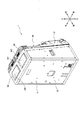
まず、構成を説明する。図1〜5に示すように、遊技機1は、いわゆるパチスロ機である。遊技機1は、コイン、メダル、遊技球又はトークン等の他、遊技者に付与された又は付与される、遊技価値の情報を記憶したカード等の遊技媒体を用いて遊技可能なものであるが、以下ではメダルを用いるものとして説明する。
First, the configuration will be described. As shown in FIGS. 1 to 5, the
なお、以後の説明において、遊技機1から遊技者に向かう側(方向)を遊技機1の前側(前方向)と称し、前側とは逆側を後側(後方向、奥行方向)と称し、遊技者から見て右側及び左側を遊技機1の右側(右方向)及び左側(左方向)とそれぞれ称する。また、前側及び後側を含む方向は、前後方向又は厚み方向と称し、右側及び左側を含む方向は、左右方向又は幅方向と称する。前後方向(厚み方向)及び左右方向(幅方向)に直交する方向を上下方向又は高さ方向と称する。
In the following description, the side (direction) from the
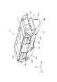
図1及び図2に示すように、遊技機1の外観は、矩形箱状の筐体2により構成されている。筐体2は、遊技機本体として前面側に矩形状の開口を有する金属製のキャビネットGと、キャビネットGの前面上部に配置された上ドア機構UDと、キャビネットGの前面下部に配置された下ドア機構DDとを有している。
As shown in FIGS. 1 and 2, the external appearance of the
キャビネットGは、2つの側面壁G2と、背面壁G3と、上面壁G4を有する。キャビネットGの上面壁G4には、左右方向に関して所定間隔隔てて、上下方向に貫通する2つの開口G41が形成されている。そして、この2つの開口G41それぞれを塞ぐように木製の板部材G42が上面壁G4に取付けられている。 The cabinet G has two side walls G2, a rear wall G3, and an upper wall G4. Two openings G41 penetrating vertically are formed in the upper surface wall G4 of the cabinet G at predetermined intervals in the left-right direction. A wooden plate member G42 is attached to the upper surface wall G4 so as to close each of the two openings G41.
図3及び図4に示すように、上ドア機構UD及び下ドア機構DDは、キャビネットGの開口の形状及び大きさに対応するように形成されている。上ドア機構UD及び下ドア機構DDは、キャビネットGにおける開口の上部及び下部を閉塞可能に設けられている。上ドア機構UDは、上側表示窓UD1を中央部に有している。上側表示窓UD1には、光を透過する透明パネルUD11が設けられている。 As shown in FIGS. 3 and 4, the upper door mechanism UD and the lower door mechanism DD are formed so as to correspond to the shape and size of the opening of the cabinet G. The upper door mechanism UD and the lower door mechanism DD are provided so that the upper part and the lower part of the opening in the cabinet G can be closed. The upper door mechanism UD has an upper display window UD1 at the center. A transparent panel UD11 that transmits light is provided in the upper display window UD1.
下ドア機構DDには、上部の略中央部に、矩形状の開口部として形成されたメイン表示窓DD4が設けられている。メイン表示窓DD4の裏面側には、キャビネットGの内部側から取付けられたリールユニットRUが装着されている。さらに、リールユニットRUの背面には、主制御基板71が取付けられている。 The lower door mechanism DD is provided with a main display window DD4 formed as a rectangular opening substantially at the center of the upper part. A reel unit RU attached from the inside of the cabinet G is mounted on the back side of the main display window DD4. Further, a main control board 71 is mounted on the back surface of the reel unit RU.
リールユニットRUは、複数種類の図柄が各々の外周面に描かれた3個のリールRL(左リール),RC(中リール),RR(右リール)を主体に構成されている。これらのリールRL,RC,RRは、それぞれが縦方向に一定の速度で回転できるように並列状態(横一列)に配設される。リールRL,RC,RRは、メイン表示窓DD4を通じて、各リールRL,RC,RRの動作や各リールRL,RC,RR上に描かれている図柄が視認可能となる。 The reel unit RU mainly includes three reels RL (left reel), RC (middle reel), and RR (right reel) in which a plurality of types of symbols are drawn on each outer peripheral surface. These reels RL, RC, RR are arranged in a side-by-side state (horizontal one row) so that they can rotate at a constant speed in the vertical direction. On the reels RL, RC, RR, the operations of the reels RL, RC, RR and the symbols drawn on the reels RL, RC, RR can be visually recognized through the main display window DD4.
メイン表示窓DD4には、その表面部に、矩形状のアクリル板等からなる透明パネルが取付け固定されており、遊技者等がリールユニットRUに触れることができないようになっている。メイン表示窓DD4の下方には、略水平面の第1,第2,第3台座部DD2a,DD2b,DD2cが形成されている。メイン表示窓DD4の右側に位置する第1台座部DD2aには、メダルを投入するためのメダル投入口DD5が設けられている。メダル投入口DD5は、遊技者によりメダルが投入される開口である。メダル投入口DD5から投入されたメダルは、クレジットされるか又はゲームにけられる。 A transparent panel made of a rectangular acrylic plate or the like is attached and fixed to the surface of the main display window DD4 so that a player or the like cannot touch the reel unit RU. Below the main display window DD4, first, second, and third pedestals DD2a, DD2b, DD2c that are substantially horizontal are formed. A medal insertion slot DD5 for inserting medals is provided in the first pedestal portion DD2a located on the right side of the main display window DD4. The medal insertion slot DD5 is an opening through which medals are inserted by the player. The medals inserted from the medal insertion slot DD5 are credited or played in the game.
メイン表示窓DD4の左側に位置する第2台座部DD2bには、クレジットされているメダルをけるための、有効ライン設定手段としての最大BETボタンDD8(MAXBETボタンともいう)が設けられている。最大BETボタンDD8が押されると、メダルの投入枚数として「3」が選択される。 The second pedestal portion DD2b located on the left side of the main display window DD4 is provided with a maximum BET button DD8 (also referred to as a MAXBET button) as an active line setting means for accepting credited medals. When the maximum BET button DD8 is pressed, “3” is selected as the number of inserted medals.
最大BETボタンDD8の前面側には、遊技者の操作によりリールRL,RC,RRを回転駆動させるとともに、メイン表示窓DD4内で図柄の変動表示を開始させるスタートレバーDD6が設けられている。スタートレバーDD6は、所定の角度範囲で傾動自在に取付けられる。 On the front side of the maximum BET button DD8, there is provided a start lever DD6 for rotating the reels RL, RC, RR by operation of the player and for starting the variable display of symbols in the main display window DD4. The start lever DD6 is attached to be freely tilted within a predetermined angle range.
スタートレバーDD6の右側で、第3台座部DD2cの前面側には、遊技者の押下操作(停止操作)により3個のリールRL,RC,RRの回転をそれぞれ停止させるための3個のストップボタンDD7L,DD7C,DD7Rが設けられている。 On the right side of the start lever DD6, on the front side of the third pedestal portion DD2c, three stop buttons for stopping the rotation of the three reels RL, RC, RR by a pressing operation (stop operation) of the player, respectively. DD7L, DD7C, DD7R are provided.
最大BETボタンDD8の近傍には、図示しないC/Pボタンが設けられている。C/Pボタンは、遊技者がゲームで獲得したメダルのクレジット/払出しを押しボタン操作で切り換えるものである。このC/Pボタンの切り換えにより払出しが選択されている状態(非クレジット状態)においては、下ドア機構DDの下部側のコインガードプレート部に設けたメダル払出口DD14(キャンセルシュート)からメダルが払出され、払出されたメダルは、メダル受け部DD15に溜められる。 A C / P button (not shown) is provided near the maximum BET button DD8. The C / P button is used to switch credit / payout of medals obtained by the player in the game by a push button operation. In a state in which payout is selected by switching the C / P button (non-credit state), medals are paid out from a medal payout opening DD14 (cancel chute) provided in a coin guard plate portion below the lower door mechanism DD. The paid-out medals are stored in the medal receiving section DD15.
スタートレバーDD6、及び、ストップボタンDD7L,DD7C,DD7Rの下部側には、腰部パネルDD18(腰部導光板)が配置されている。図6において、腰部パネルDD18は、アクリル板等を使用した化粧用パネルとして構成される。腰部パネルDD18には、遊技機1の機種を表す名称や種々の模様等が表示される。
A waist panel DD18 (waist light guide plate) is arranged below the start lever DD6 and the stop buttons DD7L, DD7C, DD7R. In FIG. 6, the waist panel DD18 is configured as a decorative panel using an acrylic plate or the like. On the waist panel DD18, a name indicating the model of the
また、メダル払出口DD14の左側にはスピーカDD25Lが、右側にはスピーカDD25Rが、それぞれ設けられている。スピーカDD25L,DD25Rは、遊技者に遊技に関する種々の情報を声や音楽等の音により報知する。また、メイン表示窓DD4の左側及び右側には、サブ表示装置DD19が配置されている。このサブ表示装置DD19は、例えば入賞成立時のメダルの払出枚数やクレジットされている残メダル枚数を表示する。通常は、遊技機1にクレジットされるメダルの最大枚数は50枚であるため、50以下のクレジット枚数が表示される。なお、最大枚数の50枚のメダルがクレジシットされている状態では、投入されたメダルはそのままメダル払出口DD14より払出される。また、サブ表示装置DD19は、タッチパネルを前面に備えていてもよい。
Further, a speaker DD25L is provided on the left side of the medal payout exit DD14, and a speaker DD25R is provided on the right side. The speakers DD25L and DD25R notify the player of various information related to the game by sounds such as voices and music. A sub display device DD19 is arranged on the left and right sides of the main display window DD4. The sub-display device DD19 displays, for example, the number of paid-out medals and the remaining number of credited medals at the time of winning. Normally, the maximum number of medals to be credited to the
図4に示すように、キャビネットG内は、中間支持板G1を挟んで上側に、前方に開口する上側開口部G101が形成されており、中間支持板G1を挟んで下側に、前方に開口する下側開口部G102が形成されている。本実施の形態の上側開口部G101は、本発明の開口部を構成する。キャビネットG内は、中間支持板G1を挟んで上部空間と下部空間とに仕切られており、すなわち、中間支持板G1は、キャビネットG内を上部空間と下部空間とに仕切る仕切板として機能している。上部空間は、キャビネットG内の上ドア機構UDの後側となる空間であり、表示ユニットA等が収容される。また、下部空間は、キャビネットG内の下ドア機構DDの後側となる空間であり、リールユニットRUや、遊技機1全体の動作を司る主制御基板71、サブ制御装置SS(図36参照)等が収容される。主制御基板71は、内部当籤役の決定、リールRL,RC,RRの回転及び停止、入賞の有無の判定といった、遊技機1における遊技の主な流れを制御する回路(主制御回路)を構成する。サブ制御装置SSは、画像の表示等による演出の実行を制御する回路(副制御回路)を構成する。
As shown in FIG. 4, inside the cabinet G, an upper opening G101 that opens forward is formed on the upper side with the intermediate support plate G1 interposed therebetween. A lower opening G102 is formed. The upper opening G101 of the present embodiment constitutes the opening of the present invention. The interior of the cabinet G is partitioned into an upper space and a lower space with the intermediate support plate G1 interposed, that is, the intermediate support plate G1 functions as a partition plate that partitions the interior of the cabinet G into an upper space and a lower space. I have. The upper space is a space behind the upper door mechanism UD in the cabinet G, and accommodates the display unit A and the like. The lower space is a space behind the lower door mechanism DD in the cabinet G, and includes a reel unit RU, a main control board 71 for controlling the entire operation of the
また、上ドア機構UDは、上側開口部G101を閉鎖又は開放可能であり、本発明の開閉部材を構成する。下側開口部G102は、下ドア機構DDによって閉鎖又は開放可能である。本実施の形態の上ドア機構UDは、本発明の開閉部材を構成し、キャビネットGは、本発明の遊技機本体を構成する。 Further, the upper door mechanism UD can close or open the upper opening G101, and constitutes the opening / closing member of the present invention. The lower opening G102 can be closed or opened by the lower door mechanism DD. The upper door mechanism UD of the present embodiment constitutes the opening / closing member of the present invention, and the cabinet G constitutes the gaming machine body of the present invention.
図6に示すように、下ドア機構DDは、下ドア機構DDの骨格となるベース部材160を有し、腰部パネルDD18は、ベース部材160の前面に形成されている。
As shown in FIG. 6, the lower door mechanism DD has a
図7に示すように、腰部パネルDD18の背面には腰部フィルム161、腰部ベースフィルム162、導光板163、腰部ベース部材164が設置されている。腰部フィルム161は、例えば、樹脂フィルムから構成されて腰部パネルDD18の背面に設けられており、腰部フィルム161には遊技機1の機種を表す名称や種々の模様等が印刷等により描かれている。
As shown in FIG. 7, a
腰部ベースフィルム162は、腰部フィルム161の背面に設けられている。腰部フィルム161は、腰部ベースフィルム162と腰部パネルDD18との間の空間に挿入されることにより、撓むことが防止され、平面状に設置される。
The
導光板163は、腰部ベースフィルム162の背面に設置されている。導光板163の側面には腰部パネルLED基板165が設置されており、腰部パネルLED基板165には上下方向に複数のLED165Aが並んで設置されている。
The
LED165Aは、導光板163の側方から導光板163に光を照射(投射)する。導光板163は、LED165Aから照射された光を前方に導くことにより、腰部フィルム161に描かれた遊技機1の機種を表す名称や種々の模様等を腰部パネルDD18に表示する。これにより、遊技者は、腰部パネルDD18によって遊技機1の機種を表す名称や種々の模様等を視認可能となる。
The
腰部ベース部材164は、導光板163を保持しており、腰部ベースフィルム162は、ネジ162aによって腰部ベース部材164に固定されている。これにより、導光板163は、腰部ベースフィルム162と腰部ベース部材164とに挟持される。腰部パネルLED基板165は、導光板163の側方に位置するようにして腰部ベース部材164に取付けられている。
The
図6に示すように、腰部ベースフィルム162、導光板163及び腰部ベース部材164は、一体でベース部材160に固定されている。ベース部材160の右側面には開口部168が形成されている。
As shown in FIG. 6, the
遊技機1の左右方向に延びる腰部パネルDD18と、腰部パネルDD18の背面に位置して腰部ベース部材164に保持される腰部ベースフィルム162との間には、遊技機1の前後方向に微小な隙間が形成されている。開口部168は、腰部パネルDD18と腰部ベースフィルム162の間の微小な隙間の開口端からなる。
A minute gap in the front-rear direction of the
腰部ベースフィルム162と腰部パネルDD18との間の隙間には腰部フィルム161が収容可能となっている。図7に示すように、腰部フィルム161の右端部の下部には突出部161Aが形成されており、突出部161Aは、腰部フィルム161の開口部168側の端部に形成され、腰部フィルム161の右端部から開口部168の方向に向けて突出している。
The
図6に示すように、ベース部材160の側方である右側面には腰部パネルカバー167が設けられており、腰部パネルカバー167は、ベース部材160の右側面に着脱自在に設けられている。
As shown in FIG. 6, a
図8に示すように、腰部パネルカバー167は、カバー部167Aと、突出部167Bとを備えている。図6に示すように、カバー部167Aは、ベース部材160の右側面を覆い、突出部167Bは、カバー部167Aの上端からベース部材160の左右方向中央部に向かって延びている。
As shown in FIG. 8, the
図8に示すように、カバー部167Aの下端部には係合部167aが設けられており、カバー部167Aの裏面には上下方向に離隔して係合部167b、167cが設けられている。突出部167Bの突出方向先端部には係合部167dが設けられている。
As shown in FIG. 8, an engaging
図6に示すように、ベース部材160には係合部169a〜169dが形成されている。係合部169aにはカバー部167Aの係合部167aが係合し、係合部169b、169cにはカバー部167Aの係合部167b、167cが係合する。係合部169dには突出部167Bの係合部167dが係合する。これにより、腰部パネルカバー167は、ベース部材160の右側面に位置決めされる。
As shown in FIG. 6,
図8に示すように、腰部パネルカバー167には上下方向に離隔して複数のボス部167e、167fが設けられている。腰部パネルカバー167は、キャビネットGに対して下ドア機構DDを開放した状態で、ベース部材160に設けられた図示しないネジ締結用のボス部に下ドア機構DDの背面側から図示しないネジを挿通し、挿通したネジをボス部167e、167fに螺合することで、ベース部材160に固定される。これにより、開口部168が閉鎖された状態となる。
As shown in FIG. 8, a plurality of
腰部パネルカバー167を取り外す際には、キャビネットGに対して下ドア機構DDを開放した状態で、ボス部167e、167fに螺合されているネジを外した後、各係合部の係合を解除して腰部パネルカバー167を下ドア機構DDの右方向又は前方に引き抜く。これにより、開口部168が開放された状態となる。
When removing the
このように、腰部パネルカバー167は、開口部168を閉鎖可能で、かつ開放可能に開口部168に着脱自在に設けられている。本実施の形態の腰部フィルム161は、本発明の装飾部材を構成し、腰部フィルム161を収容可能な隙間を形成する腰部ベース部材164及び腰部パネルDD18は、本発明の収容部材を構成する。腰部パネルカバー167は、本発明の閉鎖部材を構成する。
Thus, the
本実施の形態の遊技機1において、腰部フィルム161を交換する際には、キャビネットGに対して下ドア機構DDを開放した状態でベース部材160の右側面から腰部パネルカバー167を取り外し、腰部フィルム161の突出部161Aを、工具あるいは作業者の手によって把持し、腰部ベース部材164及び腰部パネルDD18をベース部材160に固定した状態で、腰部ベースフィルム162と腰部パネルDD18との間の隙間から腰部フィルム161を下ドア機構DDの右方向に引き抜くように取り出す。
In the
次いで、交換後の腰部フィルム161を腰部ベースフィルム162と腰部パネルDD18との間の隙間に挿入した後、ベース部材160の右側面に腰部パネルカバー167を固定する。
Next, after the replaced
このように、本実施の形態の遊技機1において、腰部パネルカバー167は、ベース部材160から腰部ベース部材164及び腰部パネルDD18を外すことなくベース部材160に対して着脱自在である。また、腰部パネルカバー167を開口部168から取り外した状態で、開口部168を通して腰部ベースフィルム162と腰部パネルDD18との間の隙間から腰部フィルム161を抜き出し可能、あるいは開口部168を通して腰部ベースフィルム162と腰部パネルDD18との間の隙間に挿入可能である。これにより、遊技機1に対して腰部フィルム161を容易に変更でき、遊技機1の製造コストが増大することを防止できる。
Thus, in
ここで、取り外した腰部パネルカバー167を再び取り付ける場合は、爪状の係合部167dを係合部169dにひっかけてからベース部材160に向けて近づくように回動させ、その後、軽く前方からベース部材160に向けて押し込むことで容易に取付位置を決めることができる。
Here, when reattaching the removed
腰部パネルカバー167の突出部167Bには、後方に突出した突出片167hが形成されている。この突出片167hは、上記の回動動作の妨げにならない位置に設けられており、位置決めの役割を果たすものである。
A projecting
腰部パネルカバー167のカバー部167Aの裏面には、ベース部材160(図6参照)の左右方向中央部に向かって突出した凸部167jが形成されており、この凸部167jの後方先端に緩衝材167gが設けられている。緩衝材167gは、取付時に腰部パネルカバー167が破損しないように取付時の衝撃を吸収する機能を有する。
A
また、係合部167b、167cには、前方から後方に向けて傾斜する傾斜面が設けられており、当該傾斜面は、腰部パネルカバー167の取り付けの際に前方から押し込みやすいように設けられたものである。
In addition, the engaging
さらに、腰部パネルカバー167のカバー部167Aの前方端部には、後方に突出したリブ167iが設けられている。このリブ167iは、収容された腰部フィルム161の位置がずれないように開口部168(図6参照)の少なくとも一部を閉鎖する役割を果たすものである。
Further, a rib 167i projecting rearward is provided at a front end of the
また、遊技機1の機種を変更する場合には、腰部フィルム161を変更するだけで遊技機本体を再利用できるため、遊技機1の製造コストを容易に低減することが可能となる。また、腰部パネルカバー167がヒンジ機構を用いずベース部材160に対して着脱自在であるため、ヒンジ機構を用いる場合と比較して遊技機1の製造コストを低減することができる。
When the model of the
また、本実施の形態の遊技機1によれば、腰部フィルム161は、腰部フィルム161の開口部168側の端部に、開口部168の方向に向けて突出する突出部161Aを有するので、突出部161Aを工具あるいは作業者の手によって把持することで、腰部フィルム161を腰部ベース部材164と腰部パネルDD18との間の隙間に対して容易に着脱することができ、装飾部材を容易に変更できる。
According to the
なお、突出部161Aは、腰部フィルム161の右端部の下部に限らず、例えば腰部フィルム161の右端部の上部等、任意の場所に設けることができる。また、本実施の形態では、突出部161Aは、1つとしたが、2つ以上形成されていてもよい。
The protruding
(表示ユニットA)
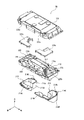
図5に示すように、表示ユニットAは、キャビネットG内の中間支持板G1上に交換可能に載置される。表示ユニットAは、画像を表示用の照射光を出射する照射ユニットBと、照射ユニットBからの照射光が照射されることにより画像を出現させるスクリーン装置Cとを有したいわゆるプロジェクションマッピング装置である。
(Display unit A)
As shown in FIG. 5, the display unit A is exchangeably mounted on the intermediate support plate G1 in the cabinet G. The display unit A is a so-called projection mapping device that includes an irradiation unit B that emits irradiation light for displaying an image, and a screen device C that causes an image to appear by being irradiated with the irradiation light from the irradiation unit B. .
ここで、プロジェクションマッピング装置は、構造物や自然物等の立体物の表面に画像を投影するためのものであって、例えば、後述のスクリーンである役物に対して、その位置(投影距離や角度等)や形状に基づいて生成される、演出情報に応じた画像を投影することにより、高度で、かつ迫力のある演出を可能とする。 Here, the projection mapping device is for projecting an image on the surface of a three-dimensional object such as a structure or a natural object. For example, a projection (projection distance or angle) Etc.) and an image corresponding to the effect information generated based on the shape and the like, thereby enabling an advanced and powerful effect.
図5に示すように、表示ユニットAは、前方に開口が形成された筐体A1を有する。この筐体A1は、照射ユニットBの上部を形成するプロジェクタカバーB1、及び、ミラー機構B3を備えたプロジェクタ筐体C10とで構成されている。プロジェクタ筐体C10は、底板C1、右側板C2、左側板C3、及び背板C4を有した箱方形状をなしている。プロジェクタカバーB1は、プロジェクタ筐体C10の上面に交換可能に取付けられる。 As shown in FIG. 5, the display unit A has a housing A1 having an opening formed in the front. This housing A1 is composed of a projector cover B1 forming the upper part of the irradiation unit B, and a projector housing C10 provided with a mirror mechanism B3. The projector housing C10 has a box shape having a bottom plate C1, a right plate C2, a left plate C3, and a back plate C4. The projector cover B1 is exchangeably mounted on the upper surface of the projector housing C10.
(表示ユニットA:照射ユニットB)
図9に示すように、照射ユニットBは、照射光を下方に向かって出射するプロジェクタ装置B2を有する。本実施の形態のプロジェクタ装置B2は、本発明のプロジェクタ及び電子機器を構成する。プロジェクタ装置B2からは静止画と動画とを含む画像や映像を含んだ光が投射されるので、説明の便宜上、プロジェクタ装置B2から投射される像を「画像」に統一して説明を行う。
(Display unit A: irradiation unit B)
As shown in FIG. 9, the irradiation unit B has a projector device B2 that emits irradiation light downward. Projector device B2 of the present embodiment constitutes the projector and the electronic device of the present invention. Since light including an image and a video including a still image and a moving image is projected from the projector device B2, the image projected from the projector device B2 is unified into an "image" for the sake of convenience of the description.
(表示ユニットA:照射ユニットB:プロジェクタ装置B2)
図9に示すように、プロジェクタ装置B2は、プロジェクタカバーB1に取付けられ、キャビネットG内の後部に配置されている(図4参照)。プロジェクタカバーB1は、プロジェクタ筐体C10の右側板C2及び左側板C3に取付けられており、上側カバー171及び下側カバー172を有する。
(Display unit A: Irradiation unit B: Projector device B2)
As shown in FIG. 9, the projector device B2 is attached to the projector cover B1, and is arranged at the rear of the cabinet G (see FIG. 4). The projector cover B1 is attached to the right side plate C2 and the left side plate C3 of the projector housing C10, and has an
プロジェクタカバーB1の内部には図示しないレンズユニットや光学機構B24(図36参照)が設けられている。 A lens unit (not shown) and an optical mechanism B24 (see FIG. 36) are provided inside the projector cover B1.
レンズユニットは、光学機構B24の複数のLED光源から出射してDMD(Digital Micromirror Device)で反射した照射光を、レンズ等を介して下方のミラー機構B3に向けて出射するように配置されている。 The lens unit is arranged so that irradiation light emitted from a plurality of LED light sources of the optical mechanism B24 and reflected by a DMD (Digital Micromirror Device) is emitted toward a lower mirror mechanism B3 via a lens or the like. .
(表示ユニットA:照射ユニットB:ミラー機構B3)
図10、図11に示すように、プロジェクタ筐体C10は、底板C1、右側板C2、左側板C3、及び背板C4を有した箱方形状をなしている。
(Display unit A: irradiation unit B: mirror mechanism B3)
As shown in FIGS. 10 and 11, the projector housing C10 has a box-like shape having a bottom plate C1, a right plate C2, a left plate C3, and a back plate C4.
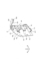
図9に示すように、プロジェクタ装置B2の下方(照射光の出射方向)には、ミラー機構B3が配置されている。ミラー機構B3は、ミラーホルダ173と、ミラーホルダ173に支持される光学ミラー174と、ミラーホルダ173及び光学ミラー174を支持するミラーホルダブラケット175とから構成されている。ミラーホルダブラケット175は、プロジェクタ筐体C10の底板C1に固定されている。
As shown in FIG. 9, a mirror mechanism B3 is disposed below the projector device B2 (in the emission direction of the irradiation light). The mirror mechanism B3 includes a
図12に示すように、ミラーホルダブラケット175は、上面から見た場合にコの字形の傾斜面175Aを有する。図9に示すように、傾斜面175Aは、プロジェクタ筐体C10の背面側である背板C4から前面側に向かって下方に傾斜している。本発明のプロジェクタ筐体C10は、本発明のユニットを構成する。
As shown in FIG. 12, the
ミラーホルダ173及び光学ミラー174は、傾斜面175Aに支持されている。これにより、プロジェクタ装置B2から下方に照射された光は、光学ミラー174によって前方に反射される。
The
本実施の形態のミラーホルダ173は、本発明の保持部材を構成し、光学ミラー174は、本発明の光学部材を構成する。ミラーホルダブラケット175は、本発明の傾斜部を構成する。
The
図10に示すように、プロジェクタ筐体C10の背面側に設けられたミラーホルダブラケット175の後部175B、175Cは、背板C4から斜め上後方に突出している。
As shown in FIG. 10, the
背板C4には左右方向に開口する開口部176Aが形成されており、ミラーホルダブラケット175の後部175B、175Cは、開口部176Aを通して背板C4の後方に突出している。これにより、ミラーホルダブラケット175に保持されているミラーホルダ173及び光学ミラー174の上端が開口部176Aを通して背板C4の後方に突出している。
An
図9に示すように、底板C1には溝部176Bが形成されている。溝部176Bは、ミラーホルダブラケット175の前端に対して前方に形成されており、溝部176Bには光学ミラー174の傾斜方向の下端部が挿入可能となっている。光学ミラー174の傾斜方向の下端部を受け入れる構成としては、溝部176Bに代えて底板C1を貫通する開口部であってもよいし、例えば溝部176Bの底面が開口された構成等、溝部176Bと開口部とを組み合わせた構成であってもよい。
As shown in FIG. 9, a
図12に示すように、ミラーホルダブラケット175の左右方向の中央部及び後部175B、175Cの傾斜面175Aには凹部175a〜175cが形成されており、凹部175a〜175cの底部には貫通穴175d〜175fが形成されている。
As shown in FIG. 12,
ミラーホルダ173の下面には3つのねじ173aが形成されている(図11参照)。ねじ173aは、ミラーホルダ173をミラーホルダブラケット175に取り付けた状態でミラーホルダ173の下面から斜め下後方に突出している。すなわち、ねじ173aは、ミラーホルダ173対して垂直な方向に突出するよう立設されている。
Three
図14に示すように、ねじ173aは、それぞれミラーホルダ173の貫通穴175d〜175fを貫通して突出方向先端部がミラーホルダブラケット175から斜め下後方に突出している。
As shown in FIG. 14, the
ねじ173aの突出方向先端部にはワッシャ177Aを介してナット177が螺合されている。ミラーホルダ173の下面とミラーホルダブラケット175の傾斜面175Aとの間にはコイルばね178が介装されており、コイルばね178は、ねじ173aの周囲を覆っている。コイルばね178の下端部は、凹部175a〜175cに挿入されており、傾斜面175Aよりも下方に位置している。コイルばね178は、ミラーホルダ173をミラーホルダブラケット175から離れる方向に付勢している。
A
図10に示すように、ミラーホルダブラケット175の後部175B、175Cは、背板C4から後方に突出しており、後部175B、175Cの下方にねじ173aの突出方向先端部及びナット177が設けられている。このため、ねじ173aの突出方向先端部及びナット177は、背板C4からプロジェクタ筐体C10の外部に露出している。
As shown in FIG. 10, the
図11に示すように、底板C1には開口部176Cが形成されており、ねじ173aの突出方向先端部及びナット177は、開口部176Cを通して底板C1からプロジェクタ筐体C10の外部に露出している。
As shown in FIG. 11, an opening 176C is formed in the bottom plate C1, and a tip end of the
ミラーホルダブラケット175の下面(ミラー取付面と反対側の面)は、同一方向に傾斜する傾斜面となっており、3つのねじ173aは、ミラーホルダブラケット175の下面から同一方向に突出している。
The lower surface of mirror holder bracket 175 (the surface opposite to the mirror mounting surface) is an inclined surface that is inclined in the same direction, and three
本実施の形態の遊技機1において、ねじ173a及びナット177が底板C1及び背板C4からプロジェクタ筐体C10の外部に露出しているので、プロジェクタ筐体C10の外部から図示しない調整装置がナット177を操作可能となる。
In the
これにより、調整装置によって3つのナット177を同時に、あるいは個々に操作し、ねじ173aに対してナット177が緩む方向に回転されると、コイルばね178にミラーホルダ173が付勢されてミラーホルダ173とミラーホルダブラケット175との間の距離が広がる。
Accordingly, when the three
一方、ねじ173aに対してナット177が締まる方向に回転されると、コイルばね178が縮んでミラーホルダ173とミラーホルダブラケット175との間の距離が縮まる。
On the other hand, when the
このようにしてミラーホルダ173とミラーホルダブラケット175との間の距離を調整することにより、プロジェクタ装置B2と光学ミラー174との距離や、光学ミラー174の姿勢又は角度を調整して、プロジェクタ装置B2から光学ミラー174までの光路長と、プロジェクタ装置B2から出射した照射光の進行方向に対する光学ミラー174の反射角度を微調整することができる。
By adjusting the distance between the
また、コイルばね178がミラーホルダ173をミラーホルダブラケット175から離れる方向に付勢することにより、ねじ173aとナット177との緩みが防止される。
Further, the
図13に示すように、ミラーホルダブラケット175には凹部175G,175H,175Iが形成されており、ねじ173aの突出方向先端部とナット177とは、凹部175G,175H,175Iに収容されている。
As shown in FIG. 13, recesses 175G, 175H, and 175I are formed in the
すなわち、ミラーホルダブラケット175には、凹部175G,175H,175Iを形成する壁部175g,175h,175iが設けられており、壁部175g,175h,175iは、ミラーホルダブラケット175から外方に突出したねじ173aの突出方向先端部よりもさらに外方(斜め下後方)に突出している。これにより、ねじ173aの一部とナット177とは、壁部175g,175h,175iによって覆われている。本実施の形態のねじ173a及びナット177は、本発明の固定部材を構成し、壁部175g,175h,175iは、本発明の突出部を構成する。コイルばね178は、本発明の付勢部材を構成する。
That is, the
図15に示すように、ミラーホルダブラケット175の下面には、ネジ穴175jを有する凹部175Jが形成されている。凹部175Jは、ミラーホルダブラケット175の下面から上方に窪んでいる。
As shown in FIG. 15, a
底板C1にはネジ溝176dを有する凸部176Dが形成されており、凸部176Dは、底板C1の上面176uから上方に突出し、凹部175Jに嵌合している。ネジ溝176dは、凸部176Dから底板C1を貫通するように形成されている。なお、底板C1の上面176uは、本発明のユニットの底面を構成する。
A convex portion 176D having a
凹部175J及び凸部176Dは、ミラーホルダブラケット175及び底板C1の左端部及び右端部にそれぞれ2か所ずつ設けられている。ミラーホルダブラケット175及び底板C1の左端部及び右端部のそれぞれに設けられた2つの凹部175J及び凸部176Dは、ミラーホルダブラケット175及び底板C1の前後方向に所定の距離だけ離れた位置に配置されている。
The
図15では、ミラーホルダブラケット175及び底板C1の右端部に形成された凹部175J及び凸部176Dを示しており、ミラーホルダブラケット175及び底板C1の左端部に形成された凹部175J及び凸部176Dの図示を省略している。
FIG. 15 shows the
ネジ溝176dにはネジ穴175jを通してネジ179が螺合されている。したがって、ミラーホルダブラケット175は、各凸部176Dが各凹部175Jに嵌合していることにより前後左右方向への移動が規制された状態(位置決めされた状態)で、ネジ179によって底板C1に固定されている。
A
(上ドア機構UD及びスクリーン装置C)
図16、図17に示すように、上ドア機構UDは、フロントパネル180とバックパネル181とを有する。フロントパネル180の前面にはスクリーン装置Cが取付けられている。スクリーン装置Cは、遊技者に対向しており、スクリーン装置Cの後方に光学ミラー174及びプロジェクタ装置B2が設置されている。
(Upper door mechanism UD and screen device C)
As shown in FIGS. 16 and 17, the upper door mechanism UD has a
スクリーン装置Cは、メインスクリーン182と、メインスクリーン182の背面に密着して取付けられた投影用シート183とを備えている(図20参照)。メインスクリーン182は、透光性を有するアクリル板等の樹脂又はガラス板等を主たる素材とし、全面に亘って均等な厚みを有するように形成されている。本実施の形態のメインスクリーン182は、本発明のスクリーンを構成し、投影用シート183は、本発明の被投影部材を構成する。メインスクリーン182及び投影用シート183は、本発明の表示部材を構成する。
The screen device C includes a
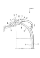
図20に示すように、メインスクリーン182は、左右方向の中央に位置し、平面形状の平面部182aと、平面部182aの左右両側の側縁から後方に向けて湾曲して延びる湾曲部182bとを有する。
As shown in FIG. 20, the
投影用シート183は、後方から画像が投影されることで表示される透過式のスクリーンであり、プロジェクタ装置B2から投射された光が入射する背面側の入射面と、入射面に入射した光が透過することで画像が投影される前面側の表示面と、を有する。
The
投影用シート183は、例えば、透光性を有するガラス板、アクリル板、樹脂製フィルムを主たる素材として、全面に亘って均等な厚みを有するように形成され、非投影時に乳白色、半透明、あるいはグレー色を呈する。
The
投影用シート183は、左右方向の中央に位置する平面部183aと、平面部183aの左右両側の側縁から後方に向けて湾曲する湾曲部183bと、を備えている。
The
投影用シート183の入射面(背面側の表面)に対して、プロジェクタ装置B2から投射された光が入射することによって、投影用シート183の表示面(前面側の表面)に、遊技に関する画像(静止画像や動画像を含む画像)が表示される。
When the light projected from the projector device B2 is incident on the incident surface (rear surface) of the
メインスクリーン182は、透明に形成されており、メインスクリーン182の前方には遊技者の視界を遮る構造が存在しないため、投影用シート183に画像が表示された場合、当該画像は、遊技者から視認可能となる。また、メインスクリーン182は、所定の色として黒色を有し、投影用シート183に投影される光の明度を低下可能となっている。実際には、メインスクリーン182は、投影用シート183に投影される明るい光のチラつきが抑えられる程度の所定の透過率となるような黒色を有している。これにより、投影用シート183に投影される明るい光のチラつきが抑えられ、投影用シート183に投影される画像が明瞭に視認される。
The
また、本実施の形態では、メインスクリーン182を、異なる透過率となる黒色を有するスクリーンに交換するだけで、共通の投影用シート183を用いつつ、投影用シート183に投影される画像の色味調整を行うことができる。
Further, in this embodiment, the color of the image projected on the
また、投影用シート183は、平面部183aと湾曲部183bとを有しており、平面部183aと湾曲部183bとでは奥行き方向の位置が異なるため、平面部183aと湾曲部183bの双方に画像を表示することによって、投影用シート183に表示された画像全体に立体感を付与することができる。
Further, the
また、メインスクリーン182及び投影用シート183は、それぞれ、湾曲部182b及び湾曲部183bがフォーミング(開放空間内成形)により形成されており、これにより、例えば、真空加工等により湾曲部を形成した場合と比較して、画像の変形を抑えることができる。
In the
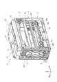
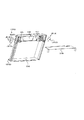
図17に示すように、フロントパネル180は、上側フレーム部185と下側フレーム部186とを備えている。下側フレーム部186は、底板187と、側板188、189とを備えている。底板187は、左右方向に延びており、側板188、189は、底板187の左右方向の両端から上方に延びている。
As shown in FIG. 17, the
図20に示すように、メインスクリーン182及び投影用シート183は、メインスクリーン182が底板187及び側板188、189に当接した状態で底板187に載置されている。
As shown in FIG. 20, the
メインスクリーン182及び投影用シート183の内周面には側板188、189に沿って上下方向に延びるシートサポート190A、190Bが設けられており(図20参照)、シートサポート190A、190Bは、図示しないネジによってメインスクリーン182及び投影用シート183を側板188、189に固定している。
Sheet supports 190A and 190B extending vertically along
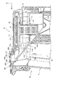
図18は、プロジェクタ装置B2から投射された光の照射範囲と上ドア機構UD側のスクリーン装置Cとの関係を示す図である。図18では、上ドア機構UD側のスクリーン装置Cの表示面を網掛けで示している。プロジェクタ装置B2から投射された光の照射範囲は、スクリーン装置Cよりも広くなっている。 FIG. 18 is a diagram showing the relationship between the irradiation range of light projected from the projector device B2 and the screen device C on the upper door mechanism UD side. In FIG. 18, the display surface of the screen device C on the side of the upper door mechanism UD is shaded. The irradiation range of the light projected from the projector device B2 is wider than that of the screen device C.
具体的には、プロジェクタ装置B2から投射された光は、スクリーン装置Cの全面(網掛けで示す領域)に入射するとともに、上ドア機構UD側のスクリーン装置Cの周縁領域を通過する。図18では、プロジェクタ装置B2から投射された光の照射範囲のうち、スクリーン装置Cの周縁領域を斜線で示している。 Specifically, the light projected from the projector device B2 is incident on the entire surface of the screen device C (the region indicated by hatching) and passes through the peripheral region of the screen device C on the upper door mechanism UD side. In FIG. 18, the peripheral area of the screen device C in the irradiation range of the light projected from the projector device B2 is indicated by oblique lines.
図19、図21に示すように、上側フレーム部185は、前壁185Aと、前壁185Aの左右方向の両側に形成された側壁185B、185Cと、前壁185Aの上端から後方に延びる上壁185Dと、後壁を構成するバックパネル181の上フレーム181Uとを有する。
As shown in FIGS. 19 and 21, the
図21、図22に示すように、前壁185Aの裏面にはスピーカ191A、191Bが設けられている。スピーカ191A、191Bは、左右方向に離隔して上側フレーム部185の収容空間192A、192Bに設置されており、ネジ194Aによって前壁185Aに固定されている。
As shown in FIGS. 21 and 22,
収容空間192A、192Bは、前壁185Aの裏面の左右方向の両側、上壁185Dの裏面の左右方向の両側及び側壁185B、185Cによってそれぞれ囲まれる空間である。
The
収容空間192A、192Bは、上側フレーム部185にスピーカ191A、191Bを設置するためのスペースに余裕を持たせるために確保される空間である。収容空間192A、192Bにおいて、スピーカ191A、191Bは、それぞれの間隔が離れるように、または、近づくように設置可能、若しくは、機種毎に異なる大きさのスピーカが設置可能である。
The
図16に示すように、バックパネル181は、フロントパネル180の後方に設置されている。バックパネル181の上フレーム181Uには左右方向に離隔するスピーカ収容部181A、181Bが設けられており、スピーカ収容部181A、181Bにはスピーカ191A、191Bが収容される。すなわち、スピーカ191A、191Bは、前後方向において前壁185Aとスピーカ収容部181A、181Bとに挟まれるようにして上側フレーム部185に収容されている。
As shown in FIG. 16, the
図21、図22に示すように、スピーカ191A、191Bの側方において収容空間192A、192Bには遮部材193A、193Bが設けられている。遮部材193A、193Bは、スピーカ191A、191Bの側方の所定の空間である中央空間192Cと収容空間192A、192Bとを仕切るように設置されており、図示しないネジによって前壁185Aに固定されている。これにより、収容空間192A、192Bは、遮部材193A、193Bによって中央空間192Cから遮られる。
As shown in FIGS. 21 and 22, shielding
遮部材193A、193Bは、スピーカ191A、191Bの設置位置や大きさ等によって収容空間192A、192Bに余分な空間がある場合に当該空間を占有するように設置可能である。図35に示すようにスピーカ191A、191Bが互いに近づくような位置に設置される場合や、スピーカ191A、191Bが大きい場合には、遮部材193A、193Bを取り外すことも可能である。本実施の形態の上側フレーム部185は、本発明の収容部材を構成する。
The shielding
図19及び図21に示すように、上側フレーム部185にはセンタスクリーンシート195及び一対のサブスクリーンシート196A、196Bが設けられており、センタスクリーンシート195及び一対のサブスクリーンシート196A、196Bは、前壁185Aの背面に取付けられている。
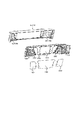
As shown in FIGS. 19 and 21, the
センタスクリーンシート195とサブスクリーンシート196A、196Bとは、それぞれの縁部(左右方向の端部)が隣接するように設置されており、隣接部195a、195bにおいて嵌合可能な形状を有している。
The
センタスクリーンシート195及びサブスクリーンシート196A、196Bは、後方から画像が投影されることにより、表示される透過式のスクリーンであり、投影用シート183と同様に、プロジェクタ装置B2から投射された光が入射する背面側の入射面と、入射面に入射した光が透過することで投影像が投影される前面側の表示面とを有する。
The
センタスクリーンシート195及びサブスクリーンシート196A、196Bは、例えば、透光性を有するガラス板、アクリル板、樹脂製フィルムを主たる素材として、全面に亘って均等な厚みを有するように形成され、非投影時に乳白色、半透明、あるいはグレー色を呈する。
The
センタスクリーンシート195及びサブスクリーンシート196A、196Bの入射面(背面側の表面)に対して、プロジェクタ装置B2から投射された光が入射することによって、センタスクリーンシート195及びサブスクリーンシート196A、196Bの表示面(前面側の表面)に、遊技に関する画像(静止画像や動画像を含む画像)が表示される。
The light projected from the projector device B2 is incident on the incident surface (the rear surface) of the
センタスクリーンシート195は、光を拡散するための拡散層、入射面側に凸となる形状を有する単位プリズムが複数配列されたプリズム層を有している。これにより、プロジェクタ装置B2から投射された光がセンタスクリーンシート195によって拡散され、センタスクリーンシート195の前面側に配置された造形物と相俟って、魅力的な演出を行うことができる。本実施の形態のサブスクリーンシート196A、196Bは、本発明の第1のシートを構成し、センタスクリーンシート195は、本発明の第2のシートを構成する。
The
図19及び図21に示すように、上側フレーム部185の前壁185Aには装飾部材197が設けられている。装飾部材197は、センタスクリーンシート195の縁部と、サブスクリーンシート196A、196Bの縁部、すなわち、隣接部195a、195bとに跨がるようにして、隣接部195a、195bの前方に設けられている。これにより、遊技者は、前方から隣接部195a、195bを視認困難となる。
As shown in FIGS. 19 and 21, a
装飾部材197には開口部197Aが形成されており、センタスクリーンシート195に投影される画像は、開口部197Aを通して遊技者に視認可能となる。
An
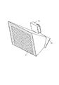
図23に示すように、装飾部材197には開口部197Aを塞ぐようにしてイルミネーションパネル(以下、単に導光パネルという)198が取付けられており、導光パネル198は、被投影部材としてのセンタスクリーンシート195と前後方向に重畳する位置、すなわち、センタスクリーンシート195に対して前方に設けられている。
As shown in FIG. 23, an illumination panel (hereinafter, simply referred to as a light guide panel) 198 is attached to the
図24に示すように、導光パネル198には顔を模した模様198aが形成されている。具体的には、導光パネル198に模様198aを描くように凹凸が形成されており、導光パネル198に光が照射されると、凹凸に光が反射して模様198aが浮かび上がるようになっている。
As shown in FIG. 24, a
図25に示すように、導光パネル198の上端には、後方に突出する山形形状の複数の突出部198Aが設けられており、これら複数の突出部198Aは、左右方向に並んでいる。
As shown in FIG. 25, at the upper end of the
図25、図26に示すように、上側フレーム部185にはLED基板199が設けられており、LED基板199は、導光パネル198の上端後方に設置されている。LED基板199には突出部198Aと対となるように複数のサイドビュータイプのLED199Aが設けられている。LED基板199は、基板保持部材199Bに保持された状態で上側フレーム部185に取り付けられている。
As shown in FIGS. 25 and 26, an
LED199Aから照射された光は、導光パネル198の突出部198Aに入射され、前方に向かった後、導光パネル198の上端において下方に反射し、導光パネル198内を下方又は側方に導かれる。このとき、導光パネル198内を下方又は側方に導かれる光が凹凸で反射して、模様198aが浮かび上がる。これにより、前方から模様198aが視認可能となる。すなわち、模様198aは、本発明の所定の識別表示を構成するものであり、突出部198Aが本発明の入射部を構成する。図23は、模様198aが視認可能(LED199Aが発光状態)な状態を示している。
The light emitted from the
また、導光パネル198にはプロジェクタ装置B2からセンタスクリーンシート195に投影される画像が表示される。図24に示すように、導光パネル198は、模様198aの一部に特定領域198bを有し、その特定領域198bの背面にあるセンタスクリーンシート195にプロジェクタ装置B2から画像が投影される。
Further, an image projected from the projector device B2 onto the
本実施の形態では、プロジェクタ装置B2から特定領域198bを介して視認可能となる画像を第1の表示態様から第2の表示態様に変化させる演出を実行可能となっている。特定領域198bを介して視認可能となる画像、すなわち、特定領域198bの背面にあるセンタスクリーンシート195にプロジェクタ装置B2から投影される画像としては、種々の画像を用いることができ、本実施の形態では後述する目玉画像241が用いられる。
In the present embodiment, an effect of changing an image that can be visually recognized from the projector device B2 via the
具体的には、導光パネル198に顔を模した模様198aが表示されている状態で、特定領域198bの背面にあるセンタスクリーンシート195に対して、第1の表示態様として正面を向いた目玉画像241がプロジェクタ装置B2から投影される(図27参照)。
More specifically, in the state where a
また、導光パネル198に顔を模した模様198aが表示されている状態で、特定領域198bの背面にあるセンタスクリーンシート195に対して、第2の表示態様として左上側を向いた目玉画像242がプロジェクタ装置B2から投影される(図28参照)。
In a state in which a
なお、第1の表示態様及び第2の表示態様としては、上述した画像に限らず、任意の画像を用いることができる。また、第3の表示態様として、例えば右上側を向いた目玉画像242を用いてもよい。
Note that the first display mode and the second display mode are not limited to the above-described images, and any images can be used. Further, as a third display mode, for example, an
図27に示す目玉画像241(第1の表示態様)から図28に示す目玉画像242(第2の表示態様)に表示態様を変化させることで、特定領域198bを介して視認可能となる画像を第1の表示態様から第2の表示態様に変化させる演出が実行可能である。
By changing the display mode from the center image 241 (first display mode) shown in FIG. 27 to the center image 242 (second display mode) shown in FIG. 28, an image that can be visually recognized through the
第1の表示態様から第2の表示態様に変化する演出を行う場合、あるいは第1の表示態様のみの演出を行う場合、さらに第2の表示態様のみによる演出を行う場合に、LED199A(図25参照)の発光により導光パネル198の模様198aが視認可能となるように表示演出を行う。LED199Aは、本発明の光源を構成し、導光パネル198は、本発明の導光部材を構成する。
The
また、センタスクリーンシート195は、プリズム層を有しているので、プロジェクタ装置B2からセンタスクリーンシート195に投影された画像(例えば、目玉画像241、242)は、キラキラ輝いているような画像として表示される。
Further, since the
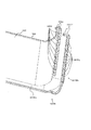
図25、図26に示すように、導光パネル198は、突出部198Aが設けられた上端部と異なる左右方向の端部に、導光パネル198から後方に向かって折り曲げられた折り曲げ部198B、198Cが形成されている。LED199Aから照射され突出部198Aを介して導光パネル198に入射された光は、導光パネル198内を下方又は側方に導かれるが、導光パネル198内を側方に導かれた光は、折り曲げ部198B、198Cを介して導光パネル198の後方に導かれた後、折り曲げ部198B、198Cの後方端部から外部に出射する。これにより、導光パネル198内を側方に導かれた光が導光パネル198の側方や前方に漏れることがない。
As shown in FIGS. 25 and 26, the
一方、導光パネル198の前面には、例えば、マジックミラー200(図25参照)が設けられている。
On the other hand, on the front surface of the
マジックミラー200は、ガラス板、アクリル、樹脂製フィルム等の透光性を有する透光性部材と、透光性部材の表面に設けられ、光を透過及び反射させる反射膜とを含んで構成されている。
The
反射膜は、例えば、透光性部材の表面に錫や銀のメッキや蒸着が施されることにより形成されている。マジックミラー200の反射率は、反射膜の厚みを調整することにより任意の反射率に設定することができる。
The reflection film is formed, for example, by plating or vapor-depositing tin or silver on the surface of the translucent member. The reflectance of the
導光パネル198の後方には本発明の発光部材を構成するプロジェクタ装置B2が設けられているので、マジックミラー200は、プロジェクタ装置B2からの光が導光パネル198に投射(照射)されないときには外方(前方及び側方)からの光が前方に反射して見える。これにより、導光パネル198の後方を前方から視認困難とすることが可能となる。
Behind the
一方、プロジェクタ装置B2から光が導光パネル198に投射(照射)されたときには前方から導光パネル198の後方側が視認可能となる。本実施の形態のマジックミラー200は、本発明の装飾部を構成する。
On the other hand, when light is projected (irradiated) from the projector device B2 to the
上記のような構成により、本実施の形態では、プロジェクタ装置B2からの光が導光パネル198に投射されないときにはマジックミラー200で光が反射して見える演出を実行可能である一方、プロジェクタ装置B2からの光が導光パネル198に投射されているときには導光パネル198の模様198aを視認可能としつつ、プロジェクタ装置B2から投影される画像が導光パネル198を通して視認可能となる。
With the above configuration, in the present embodiment, when the light from the projector device B2 is not projected on the
このように、本実施の形態の上側フレーム部185は、センタスクリーンシート195、サブスクリーンシート196A、196B及び導光パネル198によって多彩な演出を実行可能な装飾ユニットとして構成される。なお、導光パネル198に表示される表示態様は、模様198aに限定されるものではない。
As described above, the
<間接照明>
図20に示すように、側板189は、メインスクリーン182の湾曲部182bと投影用シート183の湾曲部183bに対して遊技機1の幅方向側方(左方)に設置されている。
<Indirect lighting>
As shown in FIG. 20, the
図29、図30に示すように、側板188は、湾曲部182bと湾曲部183bに対して遊技機1の幅方向側方(右方)に設置されている。
As shown in FIGS. 29 and 30, the
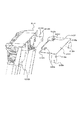
側板188は、第1の壁部188Aと、第1の壁部188Aに対して遊技機1の幅方向外側である幅方向の右方に設置される第2の壁部188Bとを備えている。
The
第1壁部188Aと第2の壁部188Bとの間には空間188Cが形成されている。第1の壁部188Aと第2の壁部188Bとは、上下方向に所定の間隔を隔てて複数設置される連結部188Dによって連結されている。
A space 188C is formed between the
側板188の後方には導光部材202及びLED基板203が設置されている。LED基板203には上下方向に並んで複数のトップビュータイプのLED203Aが設けられている。LED203Aは、導光部材202に向けて光を照射するようになっている。導光部材202は、LED203Aから入射された光を前方に導くようになっている。なお、導光部材202の前方端面側には、メインスクリーン182の右端部が重なるようにして配置されているが、メインスクリーン182が透光性を有するため、導光部材202の前方端面から前方に出射する光がメインスクリーン182の右端部によって遮られることはない。
The
このため、LED203Aから照射され、導光部材202によって導かれた光は、空間188Cによって前方の遊技者に視認可能となる。本実施の形態の空間188Cは、本発明の所定の空間を構成し、LED203Aは、本発明の発光部を構成する。導光部材202は、本発明の導光部を構成する。
For this reason, the light emitted from the
第2の壁部188Bの前方側の先端には、第1の壁部188Aの先端188aよりも後方側に凹んだ凹部188Eが形成されており、LED203Aから照射された光の少なくとも一部は、凹部188Eを通じて遊技機1の側方から視認可能となっている。なお、側板189の構成も側板188と同一であるので、説明を省略する。
At the front end on the front side of the
(プロジェクタユニットの通気構造と液体収容構造)
図16、図17に示すように、上側フレーム部185の上壁185Dには吸気口204aと排気口204bとが形成されており、吸気口204aと排気口204bとは、複数の貫通孔が集合したものから構成されている。本実施の形態の吸気口204a及び排気口204bは、本発明の通気孔を構成する。
(Ventilation structure and liquid storage structure of projector unit)
As shown in FIGS. 16 and 17, the
バックパネル181の上部には、吸気ダクト206及び排気ダクト207が設けられている。図17に示すように、吸気ダクト206は、上流側吸気口206aと下流側吸気口206bとを有し、上流側吸気口206aは、吸気口204aの真下に位置している。
An
排気ダクト207は、上流側排気口207aと下流側排気口207bとを有し、下流側排気口207bは、排気口204bの真下に位置している。ここで、上流、下流とは空気が流れる方向に対して上流、下流を示している。本実施の形態の吸気ダクト206及び排気ダクト207は、本発明の開閉部材側通気部を構成する。
The
図31、図32に示すように、キャビネットG(図5参照)に収容されるプロジェクタカバーB1にはプロジェクタ装置B2を冷却する本体側通気部209が形成されている。
As shown in FIGS. 31 and 32, a main body
本体側通気部209は、プロジェクタカバーB1の上側カバー171に形成された吸気口225aと、下側カバー172に形成された凹部225bと凹部225bを閉止するダクトカバー225cとによって吸気口225aから取り入れられた空気をプロジェクタ装置B2に流す吸気ダクト225を有する。
The main body
遊技機1の外部の空気は、吸気口204aから吸気ダクト206を通して吸気ダクト225に導入される。
Air outside the
本体側通気部209は、プロジェクタカバーB1の上側カバー171に形成された排気口226aと、下側カバー172に形成された凹部226bと凹部226bを閉止するダクトカバー226cとによってプロジェクタ装置B2を冷却した後の高温の空気を排気ダクト207に向かって流す排気ダクト226を有する。
The main body
吸気ダクト225と排気ダクト226とはプロジェクタ装置B2の後面に形成された連通路171a(図9、図32参照)と、プロジェクタ装置B2に形成された複数の開口部211(図9、図32参照)を通して連通しており、吸気ダクト225から連通路171a及び開口部211を通して流れる空気によってプロジェクタ装置B2が冷却される。
The
プロジェクタ装置B2と熱交換された高温の空気は、排気ダクト226から排気ダクト207に排出された後、排気ダクト207から排気口204bを通して遊技機1の外部に排出される。
The high-temperature air heat-exchanged with the projector device B2 is discharged from the
本実施の形態の吸気口225a及び排気口226aは、本発明の通気口を構成する。吸気口225aは、本発明の吸気部を構成し、排気口226aは、本発明の排気部を構成する。
The
図32に示すように、排気ダクト226には排気ファン208が設けられており、排気ファン208は、吸気口225aからプロジェクタカバーB1の内部に外気を吸引可能である。なお、排気ファン208に代えて吸気ダクト225に吸気ファンを設けてもよく、吸気ダクト225及び排気ダクト226のそれぞれに吸気ファン及び排気ファンを設けてもよい。
As shown in FIG. 32, the
図33に示すように、上ドア機構UDがキャビネットGの上側開口部G101(図4参照)を閉鎖した状態において、上ドア機構UD側の吸気ダクト206は、下流側吸気口206bがプロジェクタカバーB1側の吸気口225aに連通している。
As shown in FIG. 33, when the upper door mechanism UD closes the upper opening G101 (see FIG. 4) of the cabinet G, the
図34に示すように、上ドア機構UDがキャビネットGの上側開口部G101(図4参照)を閉鎖した状態において、上ドア機構UD側の排気ダクト207は、上流側排気口207aがプロジェクタカバーB1側の排気口226aに連通している。
As shown in FIG. 34, when the upper door mechanism UD closes the upper opening G101 (see FIG. 4) of the cabinet G, the
このように、吸気ダクト225及び排気ダクト226は、それぞれ遊技機1の外部と連通して、プロジェクタカバーB1の内部を通気する。本実施の形態の吸気ダクト225及び排気ダクト226は、本発明の通気部及び通気ダクトを構成する。
Thus, the
また、本実施の形態の上側カバー171と下側カバー172とからなるプロジェクタカバーB1とプロジェクタ装置B2とは、本発明のプロジェクタユニットを構成する。
In addition, the projector cover B1 and the projector device B2 including the
図17、図33に示すように、上ドア機構UD側の吸気ダクト206の上流側吸気口206aには、ゴムパッキン212が設けられている。ゴムパッキン212は、バックパネル181に設けられた吸気ダクト206と上側フレーム部185の上壁185Dに設けられた吸気口204aとの間の間隙が小さくなるよう、吸気ダクト206と吸気口204aとが連通する領域の近傍に設けられている。具体的には、ゴムパッキン212は、吸気ダクト206の上端と上壁185Dの下面との間に圧縮された状態で設置されており、ゴムパッキン212の内方に吸気口204aが設けられている。
As shown in FIGS. 17 and 33, a rubber packing 212 is provided at the
図17、図34に示すように、上ドア機構UD側の排気ダクト207の下流側排気口207bには、ゴムパッキン213が設けられている。ゴムパッキン213は、バックパネル181に設けられた排気ダクト207と上側フレーム部185の上壁185Dに設けられた排気口204bとの間の間隙が小さくなるよう、排気ダクト207と排気口204bとが連通する領域の近傍に設けられている。具体的には、ゴムパッキン213は、排気ダクト207の上端と上壁185Dの下面との間に圧縮された状態で設置されており、ゴムパッキン213の内方に排気口204bが設けられている。
As shown in FIGS. 17 and 34, a rubber packing 213 is provided at the
本実施の形態のゴムパッキン212、213は、本発明の緩衝部材を構成する。なお、吸気ダクト206と吸気口204aとの間の間隙、及び排気ダクト207と排気口204bとの間の間隙が小さくなるものであれば、ゴムパッキン212、213に限らず、他のシール部材を用いてもよい。
The
図31、図32に示すように、下側カバー172の下部には、吸気側液体収容部214と排気側液体収容部215とがそれぞれ別体で設けられている。
As shown in FIGS. 31 and 32, an intake-side
吸気側液体収容部214は、吸気ダクト225の下部に位置するように下側カバー172に取付けられており、下側カバー172に対して着脱可能となっている。
The suction-side
排気側液体収容部215は、排気ダクト226の下部に位置するように下側カバー172に取付けられており、下側カバー172に対して着脱可能となっている。
The exhaust-side
吸気側液体収容部214は、前側から後側に向かって下方に傾斜する傾斜部214Aと、傾斜部214Aの傾斜方向下端部に設けられた箱状の収容部214Bと、収容部214Bの背面側である後壁214bから後方に突出する部214Cとを有する。
The suction-side
排気側液体収容部215は、前側から後側に向かって下方に傾斜する傾斜部215Aと、傾斜部215Aの傾斜方向下端部に設けられた箱状の収容部215Bと、収容部215Bの背面側である後壁215bから後方に突出する部215Cとを有する。なお、後壁214b、215bは、本発明の所定の壁部を構成する。
The exhaust-side
図33に示すように、上ドア機構UDがキャビネットGの上側開口部G101(図4参照)を閉鎖した状態において、吸気側液体収容部214は、傾斜部214Aの上端が吸気ダクト206の下流側吸気口206bの下方で、かつ、下流側吸気口206bと上下方向で重なるように下側カバー172に取付けられている。
As shown in FIG. 33, when the upper door mechanism UD closes the upper opening G101 (see FIG. 4) of the cabinet G, the upper end of the
また、吸気側液体収容部214の傾斜部214Aの上端は、プロジェクタカバーB1の上側カバー171に形成された凹部225bの上流端よりも前方に位置している。これにより、吸気口204aから吸気ダクト206に導入された空気は吸気ダクト225に導かれる一方で、吸気口204aから吸気ダクト206に侵入したジュース等の液体は、吸気ダクト225に侵入せずに、吸気ダクト206の下流側吸気口206bから流下、あるいは滴下して吸気側液体収容部214の傾斜部214Aに流入するようになっている。
Further, the upper end of the
これにより、吸気側液体収容部214には、吸気口204aから吸気ダクト206を通してプロジェクタカバーB1に侵入したジュース等の液体が収容される。すなわち、吸気ダクト206を通してプロジェクタカバーB1に液体が侵入すると、液体は、傾斜部214Aに沿って下方に移動した後、収容部214Bに収容されて貯留される。収容部214Bに収容される液体が満杯になると、液体は、部214Cから後方に排出される。
Thus, the liquid such as juice that has entered the projector cover B1 from the
図34に示すように、上ドア機構UDがキャビネットGの上側開口部G101(図4参照)を閉鎖した状態において、排気側液体収容部215は、傾斜部215Aの上端が排気ダクト207の上流側排気口207aの下方で、かつ、上流側排気口207aと上下方向で重なるように下側カバー172に取付けられている。
As shown in FIG. 34, in a state where the upper door mechanism UD has closed the upper opening G101 (see FIG. 4) of the cabinet G, the upper end of the
また、排気側液体収容部215の傾斜部215Aの上端は、プロジェクタカバーB1の上側カバー171に形成された凹部226bの下流端よりも前方に位置している。これにより、排気口204bから排気ダクト207に侵入したジュース等の液体は、排気ダクト226に侵入せずに、排気ダクト207の上流側排気口207aから流下、あるいは滴下して排気側液体収容部215の傾斜部215Aに流入するようになっている。
Further, the upper end of the
これにより、排気側液体収容部215には、排気口204bから排気ダクト207を通してプロジェクタカバーB1に侵入したジュース等の液体が収容される。すなわち、排気ダクト207を通してプロジェクタカバーB1に液体が侵入すると、液体は、傾斜部215Aに沿って下方に移動した後、収容部215Bに収容されて貯留される。収容部215Bに収容される液体が満杯になると、液体は、部215Cから後方に排出される。
Thus, the liquid such as juice that has entered the projector cover B1 from the
本実施の形態の吸気側液体収容部214及び排気側液体収容部215は、本発明の液体収容部を構成する。吸気側液体収容部214は、本発明の吸気側液体収容部を構成し、排気側液体収容部215は、本発明の排気側液体収容部を構成する。部214C、215Cは、本発明の部を構成する。部214Cは、本発明の吸気側部を構成し、部215Cは、本発明の排気側部を構成する。
The intake-side
(表示ユニットA:照射ユニットB:プロジェクタ装置B2の電気的及び光学的構成)
図36に示すように、プロジェクタ装置B2は、電気的な構成要素として、プロジェクタ制御基板B23、光学機構B24、及び中継基板CKを備えている。プロジェクタ装置B2には、中継基板CKを介して後述するサブ制御装置SSが接続される。サブ制御装置SSは、スクリーンや役物の演出動作に応じて、プロジェクタ制御基板B23を制御し、光学機構B24を介して、スクリーンや役物に照射光を投影することにより、視覚的な演出として映像を表示する。また、表示ユニットAの組み立て工程等においては、プロジェクタ装置B2の中継基板CKに調整用PC(パーソナルコンピュータ)1000が接続される。この調整用PC(パーソナルコンピュータ)1000は、プロジェクタ装置B2により投影される照射光の位置調整やピント初期設定を行うために用いられる。
(Display unit A: Irradiation unit B: Electrical and optical configuration of projector device B2)
As shown in FIG. 36, the projector device B2 includes a projector control board B23, an optical mechanism B24, and a relay board CK as electrical components. A sub-control device SS described later is connected to the projector device B2 via a relay board CK. The sub-control device SS controls the projector control board B23 in accordance with the production operation of the screen or the accessory, and projects the irradiation light on the screen or the accessory via the optical mechanism B24, thereby providing a visual effect. Display video. Further, in the assembling process of the display unit A and the like, the adjustment PC (personal computer) 1000 is connected to the relay board CK of the projector device B2. The adjustment PC (personal computer) 1000 is used for adjusting the position of the irradiation light projected by the projector device B2 and performing initial setting of focus.
なお、本実施の形態においては、プロジェクタ装置B2の調整機器として調整用PC1000を採用しているが、プロジェクタ装置B2の調整機器としては、調整用プログラム(アプリケーションソフト)がインストールされたタブレットPCやいわゆるスマートフォン、あるいは専用の端末装置であってもよい。
In the present embodiment, the
プロジェクタ制御基板B23は、制御LSI881、EEPROM(登録商標)882、DLP(登録商標)制御回路883及びLEDドライバ884を備える。光学機構B24は、レンズユニットの周辺に配置される構成要素として、R(赤)、G(緑)、B(青)の各色光を発するLED光源、DMD、レンズユニットの投射についてフォーカス調整を行うためのフォーカス機構等を備える。
The projector control board B23 includes a
制御LSI881は、サブ制御装置SSの指令に基づいて、照射光を投影するようにDLP制御回路883を制御する。制御LSI881は、サブ制御装置SSの指令に基づいて、フォーカス機構を制御して投射レンズを光軸方向に移動させることにより、照射光の投影に際してフォーカス調整を行う。EEPROM882には、制御LSI881による制御プログラムやプロジェクタ装置B2の設定・調整に関わるデータが記憶されている。
The
プロジェクタ装置B2のDLPシステムは、主として、DLP制御回路883、LEDドライバ884、並びに光学機構B24のLED光源及びDMDにより構成される。
The DLP system of the projector device B2 mainly includes a
DMDは、半導体チップの主面上に、表示解像度に応じたピクセル相当のミラーを集積したものである。DMDは、各ミラーの直下にあるメモリー素子の静電界作用により、主面に対して各ミラーが対角線に沿う軸周りに+10°又は−10°傾くように構成されたものである。このような構成により、DMDの各ミラーは、ON状態(所定方向に光を反射する状態)とOFF状態(所定方向外に光を反射する状態)とに切り換えられる。すなわち、DMDの各ミラーは、ON状態のとき、LED光源から図示しないダイクロイックミラー等を介して入射した光を、再びダイクロイックミラー等を介してレンズユニットへと導く一方、OFF状態のとき、LED光源からダイクロイックミラー等を介して入射した光をレンズユニット以外の方向に向けて反射する。 The DMD is such that a mirror corresponding to a pixel corresponding to a display resolution is integrated on a main surface of a semiconductor chip. The DMD is configured such that each mirror is inclined + 10 ° or −10 ° around an axis along a diagonal line with respect to a main surface by an electrostatic field effect of a memory element immediately below each mirror. With such a configuration, each mirror of the DMD is switched between an ON state (a state in which light is reflected in a predetermined direction) and an OFF state (a state in which light is reflected outside a predetermined direction). That is, when each mirror of the DMD is in the ON state, the light incident from the LED light source through a dichroic mirror or the like (not shown) is guided again to the lens unit through the dichroic mirror or the like. From the lens via a dichroic mirror or the like, and is reflected toward a direction other than the lens unit.
DLP制御回路883は、LED光源を駆動するLEDドライバ884を制御し、LED光源からのRGB各色の光を図示しないダイクロイックミラー等を介して時分割方式でDMDに入射させる。このとき、DLP制御回路883は、投影する映像に応じて、どのタイミングでどのピクセルに対応したミラーをON状態又はOFF状態とするか、すなわち、RGB各色の光のうちどの色の光をどのタイミングで所定方向に反射させるかを判定し、DMDの各ミラーのON・OFF状態を制御する。
The
このようなDLP制御回路883の制御により、DMDで所定方向に反射した光は、レンズユニットへと進み、投射レンズを透過することでミラー機構B3に入射し、最終的にミラー機構B3(図5参照)で反射することによって投影対象へと導かれる。これにより、投影対象となるスクリーンや役物に対して照射光が投影され、演出に応じた映像が形成される。
Under the control of the
本実施の形態において、プロジェクタ装置B2は、いわゆるDLPプロジェクタとして構成される。また、プロジェクタ装置B2は、ミラー機構B3によって照射光を折り返すことにより投影対象までの投影距離を稼ぐとともに、例えばコントラスト比を1000:1とすることによって、照射光の投影距離をできるだけ短くするようにしている。これにより、プロジェクタ装置B2を備えた表示ユニットAは、より安価かつ小型に構成されるとともに、遊技機1のキャビネットGにおける限られたスペースに対して容易に搭載される。
In the present embodiment, projector device B2 is configured as a so-called DLP projector. In addition, the projector device B2 increases the projection distance to the projection target by turning back the irradiation light by the mirror mechanism B3, and shortens the projection distance of the irradiation light as much as possible by, for example, setting the contrast ratio to 1000: 1. ing. Accordingly, the display unit A including the projector device B2 is configured to be cheaper and smaller, and is easily mounted in a limited space in the cabinet G of the
[遊技機1の電気的構成]
次に、遊技機1の電気的構成について、図37を参照して説明する。図37は、遊技機1の電気的構成を示すブロック図である。
[Electrical configuration of gaming machine 1]
Next, an electrical configuration of the
図37に示すように、遊技機1は、キャビネットGに配設された主制御基板71と、下ドア機構DDに配設された副制御基板72とを有している。主制御基板71には、リール中継端子板51と、設定用鍵型スイッチ52と、キャビネット側中継基板53と、ドア中継端子板54と、電源装置44の電源基板44bとが電気的に接続されている。
As shown in FIG. 37, the
リール中継端子板51は、各リールRL、RC、RRのリール本体の内側に配設されている。このリール中継端子板51は、各リールRL、RC、RRのストップボタンDD7L、DD7C、DD7Rに電気的に接続されており、主制御基板71からストップボタンDD7L、DD7C、DD7Rに出力される信号を中継する。 The reel relay terminal plate 51 is disposed inside the reel body of each of the reels RL, RC, RR. The reel relay terminal plate 51 is electrically connected to the stop buttons DD7L, DD7C, DD7R of the reels RL, RC, RR, and outputs signals output from the main control board 71 to the stop buttons DD7L, DD7C, DD7R. Relay.
ステッピングモータ51L、51C、51Rは、所定の開始条件の成立、すなわちスタートレバーDD6が遊技者により操作されたこと(開始操作)に基づき、各リールRL、RC、RRを回転させることにより図柄を変動させる。ステッピングモータ51L、51C、51Rは、図柄変動手段を構成する。設定用鍵型スイッチ52は、遊技機1の設定を変更する際又は遊技機1の設定を確認する際に使用する。
The stepping
キャビネット側中継基板53には、外部集中端子板56と、ホッパ機構HPと、メダル補助収納庫スイッチ57とが電気的に接続されている。このキャビネット側中継基板53は、主制御基板71から外部集中端子板56、ホッパ機構HP、メダル補助収納庫スイッチ57に出力される信号を中継する。つまり、外部集中端子板56、ホッパ機構HP及びメダル補助収納庫スイッチ57は、キャビネット側中継基板53を介して主制御基板71に接続されている。
The cabinet
外部集中端子板56は、キャビネットGに取付けられており、メダル投入信号、メダル払出信号、外部信号1〜4及びセキュリティ信号等の信号を遊技機1の外部へ出力するために設けられている。
The external centralized terminal board 56 is attached to the cabinet G, and is provided for outputting signals such as a medal insertion signal, a medal payout signal,
メダル補助収納庫スイッチ57は、図示しないメダル補助収納庫を貫通している。このメダル補助収納庫スイッチ57は、メダル補助収納庫がメダルで満杯になっているか否かを検出する。 The medal auxiliary storage switch 57 penetrates a medal auxiliary storage not shown. The medal auxiliary storage switch 57 detects whether or not the medal auxiliary storage is full of medals.
電源装置44の電源基板44bには、電源スイッチ44aが接続されている。この電源スイッチ44aは、遊技機1に必要な電源を供給するときにONにする。
A
ドア中継端子板54には、メダル投入口DD5に繋がって下ドア機構DDの裏側に配置されたメダルセレクタ(図示せず)に配置されたメダルセンサ46、ドア開閉監視スイッチ61、BETスイッチ62、精算スイッチ63、スタートスイッチ64、ストップスイッチ基板65、遊技動作表示基板66及び副中継基板69が接続されている。
On the door
メダルセンサ46、ドア開閉監視スイッチ61、BETスイッチ62、精算スイッチ63、スタートスイッチ64、ストップスイッチ基板65、遊技動作表示基板66及び副中継基板69は、ドア中継端子板54を介して主制御基板71に接続されている。
The
メダルセンサ46は、メダルが図示しないセレクタ内を通過したことを検出して、その検出結果を主制御基板71に出力する。ドア開閉監視スイッチ61は、上ドア機構UD及び下ドア機構DDの開閉を報知するためのセキュリティ信号を遊技機1の外部へ出力する。
The
BETスイッチ62は、MAXベットボタンDD8及び1ベットボタンが遊技者により押されたことを検出して、その検出結果を主制御基板71に出力する。
The
精算スイッチ63は、精算ボタンが遊技者により押されたことを検出して、その検出結果を主制御基板71に出力する。スタートスイッチ64は、スタートレバーDD6が遊技者により操作されたこと(開始操作)を検出して、その検出結果を主制御基板71に出力する。
The
ストップスイッチ基板65は、回転しているリールを停止させるための回路と、停止可能なリールをLED等により表示するための回路を構成する基板である。このストップスイッチ基板65には、3つのリールRL、RC、RRに対応するストップスイッチ17Sが設けられている。ストップスイッチ17Sは、リールRL、RC、RRの回転を停止させるための停止操作、すなわち各ストップボタンDD7L、DD7C、DD7Rが遊技者により押されたことを検出する各ストップボタンDD7L、DD7C、DD7Rに対応するストップスイッチ17Sは、停止操作検出手段を構成する。
The
遊技動作表示基板66は、メダルの投入を受け付けるとき、3つのリールRL、RC、RRが回動可能なとき及び再遊技を行うときに、投入されたメダルの枚数を7セグ表示器28に表示させるための基板である。この遊技動作表示基板66には、7セグ表示器28とLED70が接続されている。LED70は、例えば、遊技の開始を表示するマークや再遊技を行うマーク等を点灯させる。
The game
副中継基板69は、副制御基板72と主制御基板71とを接続する配線を中継する。また、副中継基板69は、副制御基板72と副制御基板72の周辺に配設された複数の基板とを接続する配線を中継する。すなわち、副中継基板69には、副制御基板72と、サウンドI/O基板81と、LED基板82と、24hドア開閉監視ユニット74と、プロジェクタ装置B2と、操作ボタン271とが電気的に接続されている。
The sub relay board 69 relays wiring connecting the sub control board 72 and the main control board 71. The sub-relay board 69 relays wiring that connects the sub-control board 72 and a plurality of boards disposed around the sub-control board 72. That is, the sub relay board 69 is electrically connected to the sub control board 72, the sound I /
副制御基板72は、ドア中継端子板54と副中継基板69を介して主制御基板71に主制御基板71から副制御基板72に一方方向にシリアル通信で接続されている。また、副制御基板72は、副中継基板69を介して、サウンドI/O基板81と、LED基板82と、24hドア開閉監視ユニット74と、プロジェクタ装置B2と操作ボタン271とに電気的に接続されている。
The sub control board 72 is connected to the main control board 71 via the door
サウンドI/O基板81は、スピーカDD25L、DD25R及びスピーカ191A、191Bへの音声の出力を行う。LED基板82は、図示しない副制御回路の制御により実行される演出に応じて、LED群75に含まれるLEDを発光させて、点滅パターンを表示する。LED基板82には、腰部パネルLED基板165、LED基板199及びLED基板203が含まれる。
The sound I /
LED群75は、リールRL、RC、RRのそれぞれに描かれた図柄列を照射するために配置され複数のフルカラーLEDで構成されたリールバックランプ(図示せず)や、LED165A、LED199A及びLED203A等も含む。
The
24hドア開閉監視ユニット74は、下ドア機構DDのフレームに下ドア機構DDの開閉を検出するためのセンサ(図示せず)が取付けられ、センサの状態に基づいて(例えば、センサがオン状態であれば閉、オフ状態であれば開)、下ドア機構DDの開閉の履歴を保存する。
The 24h door opening /
また、24hドア開閉監視ユニット74は、下ドア機構DDが開放されたときに、表示ユニット161及び画像表示装置201aにエラー表示を行うために下ドア機構DDが開放された旨の信号を副制御基板72に出力する。
Further, when the lower door mechanism DD is opened, the 24h door opening /
なお、遊技機1のドア開閉構造上、必ず下ドア機構DDを開放しないと、上ドア機構UDを開放できないように、下ドア機構DDが閉鎖された状態で上ドア機構UDをロックしているため、ドアの開閉を検出するセンサを取付けていない。
In addition, due to the door opening / closing structure of the
このように、24hドア開閉監視ユニット74は、遊技機1の副制御回路でエラーにより検出し、ホッパ機構HPの異常を検出するセンサ(図示せず)及びメダルセンサ46は、主制御回路によりエラーを検出するエラー検出手段を構成する。
As described above, the 24h door opening /
副制御基板72には、ロムカートリッジ基板76と、画像中継基板77とが接続されている。ロムカートリッジ基板76は、サブCPUにより実行される制御プログラムと、演出用の画像(画像)、音声、光(LED群75)及び通信のデータを管理するための基板である。
The ROM board 76 and the
画像中継基板77は、副制御基板72からプロジェクタ装置B2に送信される画像信号をプロジェクタ装置B2の信号規格に合わせて変換して中継する基板である。
The
以上のように、本実施の形態の遊技機1によれば、プロジェクタ筐体C10に、プロジェクタ筐体C10の背板C4側から前面側に向かって下方に傾斜する傾斜面175Aを有し、傾斜面175Aに光学ミラー174を支持するミラーホルダブラケット175が設けられている。
As described above, according to the
これに加えて、ミラーホルダブラケット175に、ミラーホルダブラケット175に対する光学ミラー174の取付け位置を調整可能なねじ173a及びナット177が設けられている。
In addition, the
これにより、ナット177を緩めたり、締め付けたりすることで、ミラーホルダブラケット175に対する光学ミラー174の取付け位置を容易に調整して光学ミラー174をミラーホルダブラケット175に固定できる。このため、プロジェクタ装置B2と光学ミラー174との距離を遊技機毎に一定にできる。このため、スクリーン装置Cに表示される画像のばらつきが発生することを防止できる。
Thus, by loosening or tightening the
また、本実施の形態の遊技機1によれば、ミラーホルダブラケット175は、プロジェクタ筐体C10の背板C4側及び底板C1側にそれぞれ設けられており、ねじ173a及びナット177が、背板C4及び底板C1から露出することでプロジェクタ筐体C10の外部から調整可能である。
According to the
これにより、調整装置によって複数のナット177を同時に操作することが可能となり、ミラーホルダブラケット175に対する光学ミラー174の取付け位置を短時間で調整することができ、光学ミラー174の取付け位置の調整作業の作業性を向上できる。
Thereby, the plurality of
また、本実施の形態の遊技機1によれば、プロジェクタ筐体C10の底板C1に光学ミラー174の傾斜方向の下端部が挿入可能な溝部176Bが形成されているので、ミラーホルダブラケット175を底板C1に近づけることできる。
Further, according to the
このため、プロジェクタ装置B2と光学ミラー174との距離を大きくすることができ、プロジェクタ装置B2から光学ミラー174を介してスクリーン装置Cに投影される画像を大きくできる。この結果、視覚効果の高い画像を表示できる。
Therefore, the distance between the projector device B2 and the
また、本実施の形態の遊技機1によれば、光学ミラー174を保持するミラーホルダ173を備えている。
According to the
さらに、光学ミラー174をミラーホルダブラケット175に固定する固定部材が、ミラーホルダ173から下方に突出するとともに、ミラーホルダブラケット175を貫通して先端部がミラーホルダブラケット175から外方に突出するねじ173aと、ねじ173aの突出方向先端部に螺合されるナット177と、ミラーホルダ173とミラーホルダブラケット175との間に介装され、ミラーホルダ173をミラーホルダブラケット175から離れる方向に付勢するコイルばね178とを備えている。
Further, a fixing member for fixing the
これに加えて、ねじ173aの一部が、ミラーホルダブラケット175から外方に突出しており、ミラーホルダブラケット175に、ミラーホルダブラケット175から外方に突出したねじ173aの突出方向先端部よりもさらに外方(斜め下後方)に突出する壁部175g〜175iが形成されている。
In addition, a part of the
これにより、ねじ173a及びナット177の周辺を壁部175g〜175iによって覆うことができる。
Thus, the periphery of the
このため、ナット177が他の部材と接触することを防止して、ナット177によって調整されたミラーホルダブラケット175に対する光学ミラー174の取付け位置が変更されることを防止できる。この結果、プロジェクタ装置B2からスクリーン装置Cに投影される画像の表示性能が悪化することを防止できる。
For this reason, it is possible to prevent the
また、本実施の形態の遊技機1によれば、ミラーホルダブラケット175の傾斜面175Aに、コイルばね178の下端部が挿入される凹部175a〜175cが形成されている。
Further, according to
これにより、コイルばね178が凹部175a〜175cに挿入される分だけミラーホルダ173とミラーホルダブラケット175との間の距離を短くでき、光学ミラー174をプロジェクタ筐体C10の底板C1により一層近づけることできる。
Thereby, the distance between the
このため、プロジェクタ装置B2と光学ミラー174との距離をより大きくすることができ、プロジェクタ装置B2から光学ミラー174を介してスクリーン装置Cに投影される画像を大きくできる。この結果、視覚効果のより一層高い画像を表示できる。
Therefore, the distance between the projector device B2 and the
また、本実施の形態の遊技機1によれば、ミラーホルダブラケット175の下面に凹部175Jが形成されており、底板C1の上面176uに、凹部175Jに嵌合する凸部176Dが形成されているので、ミラーホルダブラケット175をプロジェクタ筐体C10に位置ずれすることなく取付けることができる。このため、ミラーホルダブラケット175に対する取付け位置が調整された光学ミラー174がプロジェクタ筐体C10に対して位置ずれすることを防止できる。
According to
この結果、プロジェクタ装置B2と光学ミラー174との距離を遊技機毎に一定にでき、スクリーン装置Cに表示される画像のばらつきが発生することを防止できる。
As a result, the distance between the projector device B2 and the
なお、ミラーホルダブラケット175の下面に凸部を形成し、底板C1の上面176uに、凸部に嵌合する凹部を形成してもよい。
Note that a convex portion may be formed on the lower surface of the
また、本実施の形態の遊技機1によれば、プロジェクタカバーB1の下側カバー172に、遊技機1の外部と連通し、プロジェクタカバーB1の内部を通気する吸気ダクト225及び排気ダクト226が設けられている。
According to the
吸気ダクト225の下部には、液体を収容する吸気側液体収容部214が設けられており、排気ダクト226の下部には、液体を収容する排気側液体収容部215が設けられている。吸気側液体収容部214及び排気側液体収容部215は、別体で構成され、それぞれ独立して下側カバー172に対して着脱可能に取付けられている。
A lower portion of the
このように、プロジェクタカバーB1に吸気ダクト225と排気ダクト226とを設けることにより、吸気ダクト225から導入された空気によってプロジェクタ装置B2を冷却することができる。また、プロジェクタ装置B2と熱交換された空気を、排気ダクト226を通してプロジェクタカバーB1から排出することができる。このため、プロジェクタ装置B2を効率よく冷却できる。
Thus, by providing the
また、別体で構成された吸気側液体収容部214及び排気側液体収容部215を下側カバー172に着脱可能に取付けることにより、遊技機1の外部から吸気口204aまたは排気口204bを通して吸気ダクト225や排気ダクト226に侵入した液体を吸気側液体収容部214や排気側液体収容部215に収容できる。
In addition, by separately attaching and detaching the intake side
このため、吸気ダクト225及び排気ダクト226を通してプロジェクタカバーB1の内部に液体が侵入することを防止できる。これにより、プロジェクタ装置B2や光学ミラー174等に液体が付着することを防止でき、画像の表示性能が悪化することを防止できる。
Therefore, it is possible to prevent liquid from entering the inside of the projector cover B1 through the
さらに、吸気側液体収容部214及び排気側液体収容部215を、それぞれ独立して下側カバー172に対して着脱可能としたので、吸気側液体収容部214及び排気側液体収容部215のうち、液体の収容された吸気側液体収容部214または排気側液体収容部215を下側カバー172から取り外すことができる。このため、液体の排出作業や吸気側液体収容部214及び排気側液体収容部215のメンテナンス、又は交換を効率的に行うことができる。
Furthermore, since the intake-side
また、本実施の形態の遊技機1によれば、吸気側液体収容部214に、吸気側液体収容部214の背面である後壁214bから後方に突出する部214Cが形成されており、排気側液体収容部215に、排気側液体収容部215の背面である後壁214bから後方に突出する部215Cが形成されている。
According to the
これにより、吸気側液体収容部214及び排気側液体収容部215に収容しきれなくなった液体を部214C又は部215Cを通して外部に排出できる。
Thus, the liquid that cannot be accommodated in the intake-side
このとき、部214C、215Cがそれぞれ後方に突出しているので、これら部214C、215Cを通して排出される液体を、プロジェクタカバーB1の直下に配置された電装部品から避けるように指向させることができる。これにより、電装部品が液体に晒されることを防止して、電装部品を保護できる。 At this time, since the portions 214C and 215C protrude rearward, the liquid discharged through these portions 214C and 215C can be directed so as to avoid the electrical components disposed immediately below the projector cover B1. This prevents the electrical components from being exposed to the liquid and protects the electrical components.
さらに、プロジェクタカバーB1を傾けるだけで、吸気側液体収容部214及び排気側液体収容部215に収容された液体を部214C、215Cを介して外部に排出できるので、液体の排出作業を効率的に行うことができる。
Further, the liquid stored in the intake-side
また、本実施の形態の吸気ダクト225及び排気ダクト226は、スクリーン装置B2を有するプロジェクタカバーB1に設けられているが、これに限定されるものではない。
In addition, the
例えば、遊技機1に通気口を設け、遊技機1の内部に通気口を通して外部と通気可能な通気部を設けることにより、遊技機1の内部に設置された電装部品や遊技機1の内部の所定空間を冷却してもよい。
For example, a ventilation port is provided in the
また、本実施の形態の液体収容構造は、プロジェクタカバーB1に2つの吸気側液体収容部214及び排気側液体収容部215が設けられているが、これに限定されるものではない。
In the liquid storage structure according to the present embodiment, the projector-side cover B1 is provided with the two intake-side
例えば、液体の侵入し易い箇所に合わせて液体収容部を設置し、液体の侵入し易い箇所が2つ以上であれば、その箇所に応じて液体収容部を2つ以上でもよい。また、液体が付着することを避けるために電装部品の位置に合わせて液体収容部を複数個、個別に設けもよい。 For example, a liquid storage portion may be provided in accordance with a location where liquid easily enters, and if there are two or more locations where liquid easily enters, two or more liquid storage portions may be provided depending on the location. Further, in order to avoid the liquid from adhering, a plurality of liquid storage portions may be individually provided in accordance with the positions of the electrical components.
また、プロジェクタカバーB1に液体収容部を設けることに限定されるものではない。例えば、遊技機1の内部に液体が侵入し易い場所に液体収容部を設けてもよく、液体収容部をその場所に応じた数だけ設けてもよい。
Further, the invention is not limited to providing the liquid container in the projector cover B1. For example, the liquid storage section may be provided in a place where the liquid easily enters the inside of the
また、本実施の形態の部214C、215Cは、それぞれ収容部214B、215Bの後壁214b、215bから後方に突出して設けられているが、これに限定されるものではなく、プロジェクタ装置B2や基板等を避ける方向に液体を排出可能なように、収容部214B、215Bの壁部(例えば背面以外の側面等)から外方に突出していればよい。
In addition, although the portions 214C and 215C of the present embodiment are provided to protrude rearward from the
遊技機1の内部に液体収容部が設けられている場合には、部214C、215Cは、遊技機1の内部に設置される基板や電源ボックス等の電装部品を避ける方向に液体を排出可能なように、収容部214B、215Bの所定の壁部から外方に突出していればよい。
When the liquid storage unit is provided inside the
また、本実施の形態の遊技機1によれば、LED199Aと、LED199Aから照射される光が上端部の突出部198Aに入射されたときに、模様198aを視認可能となる導光パネル198と、導光パネル198と重畳する位置に設けられたセンタスクリーンシート195と、導光パネル198に画像を表示するための光を投射するプロジェクタ装置B2とを備えている。
According to the
さらに、導光パネル198の模様198aが視認可能となる状態において、プロジェクタ装置B2から模様198aと関連する画像(本実施の形態では、目玉画像)を導光パネル198に投影する演出を実行可能である。
Further, in a state in which the
これにより、プロジェクタ装置B2を用いた斬新で、かつ多彩な演出を行うことができ、遊技の興趣を向上できる。また、プロジェクタ装置B2から投影される画像をセンタスクリーンシート195で結像して導光パネル198に表示することにより、導光パネル198に表示される目玉がキラキラと輝いているような画像として表示できる。この結果、より一層斬新で、かつより一層多彩な演出を行うことができ、遊技の興趣をより効果的に向上できる。
Thereby, a novel and various effects using the projector device B2 can be performed, and the interest of the game can be improved. Further, by forming an image projected from the projector device B2 on the
なお、本実施の形態では、プロジェクタ装置B2から投影される画像がセンタスクリーンシート195に結像される構成について説明したが、これに限らず、導光パネル198そのものに結像される構成であってもよい。
In the present embodiment, the configuration in which the image projected from projector device B2 is formed on
また、導光パネル198は、模様198aの一部に特定領域198bを有し、特定領域198bに投影される画像を第1の表示態様(目玉画像241)から第2の表示態様(目玉画像242)に変化させる演出を実行可能であるので、導光パネル198の模様198aと目玉画像241、242の変化によるより一層斬新、でかつより一層多彩な演出を実行でき、遊技の興趣をより効果的に向上できる。なお、表示態様は、目玉画像241、242に限定されるものではない。
The
また、演出としては、プロジェクタ装置B2から投影される画像と導光パネル198の点灯の有無によって多彩な演出が実行可能である。
In addition, various effects can be performed depending on the image projected from the projector device B2 and whether or not the
導光パネル198に対してLED199Aを非点灯とした状態で導光パネル198にプロジェクタ装置B2から画像を投影する演出、導光パネル198に対してLED199Aを点灯した後に、導光パネル198にプロジェクタ装置B2から画像を投影する演出、あるいは、導光パネル198に対するLED199Aの点灯と、導光パネル198に対するプロジェクタ装置B2からの画像投影のタイミングとを同じにする演出等が考えられる。
An effect of projecting an image from the projector device B2 on the
また、特定領域198bに表示される目玉が下を向いたときに、スクリーン装置Cに目玉が向いた先(視線の先)に何らかの画像を表示する演出や、スクリーン装置Cに表示される画像の移動に応じて目玉の向きを変えるような演出が考えられる。
Further, when the eyeball displayed in the
また、模様198aの輪郭を強調できるように模様198aの輪郭に沿った画像をプロジェクタ装置B2から導光パネル198に投影するようにしてもよい。
Further, an image along the contour of the
また、導光パネル198に対するLED199Aの点灯の有無と導光パネル198に投影される画像に応じて、導光パネル198の左右のサブスクリーンシート196A、196Bや導光パネル198の下方のスクリーン装置Cの表示態様を工夫してもよい。
In addition, the left and right
なお、本実施の形態の遊技機1は、導光パネル198と重畳するようにセンタスクリーンシート195を設けているが、センタスクリーンシート195を設けなくてもよい。
Note that, in the
また、本実施の形態の遊技機1によれば、導光パネル198は、LED199Aから照射される光が入射される突出部198Aを上端部に有し、LED199Aから突出部198Aに入射された光によって所定の識別表示が前面から視認可能となるよう構成されている。また、導光パネル198は、突出部199Aを有する上端部と異なる左右方向の端部に、導光パネル198から後方に向かって折り曲げられた折り曲げ部198B、198Cが形成されている。
Further, according to
これにより、導光パネル198に入射された光を、折り曲げ部198B、198Cから遊技者に視認され難い後方に導くことができ、導光パネル198の端部から前方あるいは側方に光が漏れることを防止できる。これにより、導光パネル198に入射された光が意図しない方向、例えば、スクリーン装置Cが設置される方向に漏れることを防止して、演出効果が低下することを防止できる。
Thereby, the light incident on the
また、本実施の形態の遊技機1によれば、導光パネル198の後方に導光パネル198に向かって光を投射(照射)するプロジェクタ装置B2が設置されており、導光パネル198の前面にマジックミラー200が設けられている。
According to
マジックミラー200は、プロジェクタ装置B2から光が導光パネル198に投射(照射)されないときには外方からの光が前方に反射して見え、かつプロジェクタ装置B2から光が導光パネル198に投射(照射)されたときには前方から導光パネル198の後方側が視認可能となるよう構成されている。
When light is not projected (irradiated) from the projector device B2 to the
これに加えて、マジックミラー200は、導光パネル198に所定の識別表示が視認可能となったときに、外方からの光が前方に反射して見える演出を実行可能である。
In addition, the
これにより、LED199Aから導光パネル198に光が入射され、所定の識別表示が視認可能な演出を実行する場合に、導光パネル198の後方を視認困難とすることもできる。このため、LED199Aから導光パネル198に光を入射したときに所定の識別表示のみを視認可能とする演出を実行することができる。
Accordingly, when light is incident on the
また、本実施の形態の遊技機1によれば、サブスクリーンシート196A、196Bと、サブスクリーンシート196A、196Bに隣接して設けられたセンタスクリーンシート195とを有し、サブスクリーンシート196A、196Bの縁部とサブスクリーンシート196A、196Bの縁部に隣接するセンタスクリーンシート195の縁部とに跨がるようにして、すなわち、サブスクリーンシート196A、196Bとセンタスクリーンシート195との連結部195a、195bに跨がるようにして隣接部195a、195bの前方に装飾部材197を設けて、装飾部材197によって隣接部195a、195bを前方から視認困難とした。
Further, according to
これにより、センタスクリーンシート195とサブスクリーンシート196A、196Bとの境目を遊技者から視認困難とすることができ、遊技機1の見栄えを向上できる。
Thereby, the boundary between the
また、本実施の形態の遊技機1によれば、装飾部材197が開口部197Aを有する。さらに、プロジェクタ装置B2によってサブスクリーンシート196A、196Bとセンタスクリーンシート195とにそれぞれ異なる画像を表示し、センタスクリーンシート195に表示される画像が開口部197Aを通して遊技者に視認可能である。
According to
これにより、センタスクリーンシート195、196A、196Bを用いた多彩な演出を実行できる。これに加えて、センタスクリーンシート195とサブスクリーンシート196A、196Bとの境目に装飾部材197を設けることにより、遊技者に対してセンタスクリーンシート195とサブスクリーンシート196A、196Bとが別デバイスかのような印象を与えることが可能となる。
Thereby, various effects using the
また、本実施の形態の遊技機1よれば、スクリーン装置Cが、遊技機1の前面側に設けられたメインスクリーン182と、メインスクリーン182の裏面に設けられた投影用シート183と、メインスクリーン182及び投影用シート183の背面から画像を表示するための光を投射するプロジェクタ装置B2とを有し、メインスクリーン182は、透光性を有し、かつ黒色を有することによりメインスクリーン182を通過する光の明度を低下可能である。
According to the
これにより、メインスクリーン182を通して遊技者に視認される画像を明瞭に表示できる。すなわち、メインスクリーン182に黒色を入れて濃くすると、メインスクリーン182が暗く見えて結果的に明るい色のちらつきを抑制でき、メインスクリーン182を通して遊技者に視認される画像を明瞭に表示できる。この結果、プロジェクタ装置B2を用いた斬新な演出を実行できる。また、黒色の割合(光の透過率)の異なるメインスクリーンを入れ替えることで色味調整を行うことができ、投影用シート183を異なる機種の遊技機1で共通して使用可能となり、遊技機1の製造コストを低減できる。
Thereby, the image visually recognized by the player through the
なお、所定の色は、黒色に限定されるものではなく、メインスクリーン182を通過する光の明度を低下可能な色であれば、その他の色でもよい。また、メインスクリーン182の黒色を濃くし過ぎると(透過率を下げ過ぎると)、投影用シート183に表示される画像が見え難くなるので、投影用シート183の濃さの度合いを調整する必要があることは、言うまでもない。
The predetermined color is not limited to black, and may be any other color as long as it can reduce the brightness of light passing through the
また、本実施の形態の遊技機1によれば、上側開口部G101を有するキャビネットGと、上側開口部G101を閉鎖又は開放可能な上ドア機構UDとを備えている。
Further, according to the
キャビネットGは、プロジェクタ装置B2と、プロジェクタ装置B2を冷却する空気を流通させる本体側通気部209とを有し、上ドア機構UDは、吸気口204a及び排気口204bと、吸気口204a及び排気口204bに連通する吸気ダクト206及び排気ダクト207とを有する。
The cabinet G has a projector device B2 and a main body
さらに、上ドア機構UDが上側開口部G101を閉鎖した状態のとき、本体側通気部209と吸気口204a及び排気口204bとが連通している。
Further, when the upper door mechanism UD closes the upper opening G101, the main body
これにより、吸気口204aから吸気ダクト206及び本体側通気部209を介してキャビネットGに取り入れられた空気によってプロジェクタ装置B2を冷却し、プロジェクタ装置B2と熱交換された空気を本体側通気部209及び排気ダクト207を介して排気口204bから外部に排出することができる。この結果、プロジェクタ装置B2を効果的に冷却できる。
Thus, the projector device B2 is cooled by the air taken into the cabinet G from the
さらに、上ドア機構UDの吸気口204a及び排気口204bと連通する通気部がキャビネットG側に設けられている場合には、遊技機1機種毎に異なる装飾の上ドア機構UDを同一のキャビネットGに用いる際にキャビネットG側に設けられた通気部の配置に合わせるように上ドア機構UDの装飾や通気孔の位置を設計しなければならず、設計の自由度がなかった。
Further, when a ventilation portion communicating with the
あるいは、機種毎に異なる装飾の上ドア機構UDに合わせて、機種毎にキャビネットGの通気部の配置を変更しなければならず、キャビネットGを共通化することが困難であった。 Alternatively, the arrangement of the ventilation portion of the cabinet G must be changed for each model in accordance with the upper door mechanism UD that is different for each model, and it has been difficult to share the cabinet G.
これに対して、本実施の形態に係る遊技機1は、吸気ダクト206及び排気ダクト207がキャビネットG側ではなく上ドア機構UDに設けられているので、機種毎にキャビネットGを共通化できるとともに、上ドア機構UDの設計の自由度を向上させることができる。
On the other hand, in the
また、本実施の形態の通気構造は、キャビネットGの上側開口部G101と下側開口部G102のうちの上側開口部G101を閉鎖及び開放可能な上ドア機構UD、すなわち、上側開口部G101と下側開口部G102の少なくとも一部を閉鎖及び開放可能を上ドア機構UDに適用しているが、これに限定されるものではない。 In addition, the ventilation structure of the present embodiment has an upper door mechanism UD capable of closing and opening the upper opening G101 of the upper opening G101 and the lower opening G102 of the cabinet G, that is, the upper opening G101 and the lower opening. Although at least a part of the side opening G102 can be closed and opened in the upper door mechanism UD, the invention is not limited to this.
例えば、キャビネットGに1つの開口部を設け、この開口部を1つのドア機構で閉鎖及び開放可能なドア機構に通気構造を適用してもよい。また、キャビネットGの閉鎖及び開放の方式も、ドア機構をキャビネットGに回動自在に連結して開口部を閉鎖及び開放可能にしてもよく、ドア機構をキャビネットGに着脱自在にして開口部を閉鎖及び開放可能にしてもよい。 For example, one opening may be provided in the cabinet G, and the ventilation structure may be applied to a door mechanism capable of closing and opening this opening with one door mechanism. Further, in the method of closing and opening the cabinet G, the door mechanism may be rotatably connected to the cabinet G so that the opening can be closed and opened. It may be capable of closing and opening.
また、本実施の形態の通気構造は、遊技機の製造時にドア機構が開閉可能であって、遊技場でドア機構が開閉できない仕様の遊技機に適用されてもよい。 Further, the ventilation structure of the present embodiment may be applied to a gaming machine having a specification in which a door mechanism can be opened and closed at the time of manufacturing a gaming machine, and a door mechanism cannot be opened and closed in a game arcade.
また、本実施の形態の遊技機1によれば、バックパネル181に設けられた吸気ダクト206と上側フレーム部185の上壁185Dに設けられた吸気口204aとの間の間隙が小さくなるよう、吸気ダクト206と吸気口204aとが連通する領域の近傍にゴムパッキン212が設けられている。
According to
これに加えて、バックパネル181に設けられた排気ダクト207と上側フレーム部185の上壁185Dに設けられた排気口204bとの間の間隙が小さくなるよう、排気ダクト207と排気口204bとが連通する領域の近傍にゴムパッキン213が設けられている。
In addition, the
これにより、吸気口204aと吸気ダクト206とが連通する領域をゴムパッキン212によって密閉することができるとともに、排気口204bと排気ダクト207とが連通する領域をゴムパッキン213によって密閉することができる。このため、吸気ダクト206及び排気ダクト207を流通する空気が吸気ダクト206及び排気ダクト207から外部に漏れることを防止して、プロジェクタ装置B2の冷却効率が悪化することを防止できる。
Thus, the region where the
また、吸気口204a及び排気口204bを介して吸気ダクト206及び排気ダクト207に液体が侵入した場合に、吸気ダクト206及び排気ダクト207を流れる液体が、吸気ダクト206と吸気口204aとが連通する領域から漏れることを防止できるとともに、排気ダクト207と排気口204bとが連通する領域から漏れることを防止できる。この結果、プロジェクタ装置B2や光学ミラー174等に液体が付着することを防止できる。
When liquid enters the
また、本実施の形態の遊技機1によれば、スピーカ191A、191Bと、スピーカ191A、191Bを収容する収容空間192A、192Bを有する上側フレーム部185と、収容空間192A、192Bに設置される遮部材193A、193Bとを備え、遮部材193A、193Bは、スピーカ191A、191Bの側方の所定の空間である中央空間192Cと収容空間192A、192Bとを仕切るように設置されている。
Further, according to
これにより、同一形状の上側フレーム部185を用いて、遮部材193A、193Bの位置を変更したり、遮部材193A、193Bを取り外したりすることにより、収容空間192A、192Bに設置されるスピーカ191A、191Bの配置を変更できる。また、遮部材193A、193Bを取り外して収容空間192A、193Aを大きく取ることで、大型なスピーカを収容空間192A、192Bに設置できる。
Thereby, by changing the position of the
このため、同一形状の上側フレーム部185を用いてスピーカ191A、191Bの設置の自由度を向上でき、遊技機1の製造コストを低減できる。
For this reason, the degree of freedom of installation of the
図35に示すように、スピーカ191A、191Bの配置を変更した一例として、遮部材193A、193Bを取り外すことにより、スピーカ191A、191Bを近づけて収容空間192A、192Bに設置した状態を示す。
As shown in FIG. 35, as an example in which the arrangement of the
また、収容空間192A、192Bが中央空間192Cを挟んで2つ設けられ、2つの収容空間192A、192Bにそれぞれスピーカ191A、191Bを設置する場合には、スピーカ191A、191Bの側方に遮部材193A、193Bを設置して遮部材193A、193Bを対向させることにより、スピーカ191A、191Bから出力する音が干渉して共鳴することを防止でき、スピーカ191A、191Bの出力性能が悪化することを防止できる。
When two
また、収容空間192A、192Bの空スペースを遮部材193A、193Bが占有するので、上側フレーム部185の内部の隙間が減り、ゴト対策につながる。
Further, since the
また、スピーカ191A、191Bの側方に遮部材193A、193Bを設置し、遮部材193A、193Bをネジによって上側フレーム部185の前壁185Aに固定しているので、遮部材193A、193Bによって前壁185Aの剛性を高めることができ、スピーカ191A、191Bをネジ194Aによって前壁185Aに強固に固定できる。
Further, since the
また、本発明に係る遊技機1によれば、遮部材193A、193Bは、プロジェクタ装置B2から投射される光の少なくとも一部を遮可能であるので、画像の表示性能を向上できることに加えて、スピーカ191A、191Bの汎用性が低下することを防止できる。
According to the
すなわち、スピーカ191A、191Bの色がプロジェクタ装置B2から投影される光を反射させる色であると、プロジェクタ装置B2から投射された画像をスクリーン装置Cに高精度に表示できないおそれがあるので、プロジェクタ装置B2から投影される光を反射し難い色のスピーカ191A、191Bを用いなければならず、スピーカ191A、191Bの汎用性が低下する。
That is, if the colors of the
本実施の形態のように、遮部材193A、193Bをスピーカ191A、191Bの側方に設置すれば、遮部材193A、193Bの色を、プロジェクタ装置B2から投影される光を例えば反射しない色や、適度に反射可能な色にすることで、スピーカ191A、191Bの種類を変更することなく、プロジェクタ装置B2から投射された画像をスクリーン装置Cに綺麗に表示でき、画像の表示性能を向上できる。これに加えて、スピーカ191A、191Bの汎用性が低下することを防止できる。
If the
なお、本実施の形態の遮部材193A、193Bは、スピーカ191A、191Bの側方に設置されているが、スピーカ191A、191Bの上側や下側あるいは斜め上側や斜め下側に設置されてもよい。
Although the
また、遮部材193A、193Bは、プロジェクタ装置B2からの投射される乱反射光等を阻止するものであってもよい。
Further, the shielding
また、本実施の形態の遊技機1によれば、光を照射可能なLED203Aと、LED203Aから照射された光を前方に導く導光部材202と、側板188、189とを備えている。
According to the
側板188(側板189も側板と同じ構成であるので説明を省略する)は、第1の壁部188Aと、第1の壁部188Aに対して遊技機1の幅方向外側に設置される第2の壁部188Bとを備えており、第1の壁部188Aと第2の壁部188Bとの間には、LED203Aから照射され導光部材202によって導かれた光の少なくとも一部が遊技者に視認可能となるよう所定の空間188Cが形成されている。
The side plate 188 (the
第2の壁部188Bの前方側の先端には、第1の壁部188Aの先端188aよりも後方側に凹んだ凹部188Eが形成されており、LED203Aから照射された光の少なくとも一部が凹部188Eを通じて遊技機1の側方から視認可能である。
At the front end of the
これにより、LED203Aから導光部材202を通して第1の壁部188Aと第2の壁部188Bとの間の空間188Cに導かれた光を、第2の壁部188Bの凹部188Eを介して(第1の壁部188Aを背景として)際立たせることができる。
Accordingly, light guided from the
このため、側板188、189を間接照明として効果的に利用することができ、遊技場において台選びをしている遊技者に対して遊技機1への興味を十分に引きつけることができる。なお、本実施の形態の遊技機1は、LED203Aを導光部材202によって空間188Cに導いているが、導光部材202を設けなくてもよい。この場合、LED203Aは、所定の空間188Cの後方に配置されるのが好ましい。
For this reason, the
(第2の実施の形態)
図38〜図57は、本発明の第2の実施の形態に係る遊技機を示す図である。
(Second embodiment)
FIG. 38 to FIG. 57 are diagrams showing a gaming machine according to a second embodiment of the present invention.
<光の照射範囲とスクリーンの配置位置>
図38は、上ドア機構及びキャビネットの縦断面図である。
<Light irradiation range and screen arrangement position>
FIG. 38 is a longitudinal sectional view of the upper door mechanism and the cabinet.
図38では、プロジェクタ9020から投射された光の照射範囲を、一点鎖線を用いて示している。第1の実施の形態と同様に、プロジェクタ9020から投射された光は、下向きに進行した後、ミラー9030によって前方に向けて反射される(図28参照)。
In FIG. 38, the irradiation range of the light projected from the
後述するように、上ドア機構UDには、スクリーンシート1046、スクリーンシート1056、及び、スクリーンシート1057が設けられている(図41及び図42参照)。プロジェクタ9020から投射された光は、スクリーンシート1046、スクリーンシート1056、及び、スクリーンシート1057のそれぞれに対して後方(背面側)から入射し、これらのスクリーンシートの前面側(表示面)に画像が表示されることになる。
As described later, the upper door mechanism UD is provided with a
以下、詳述する。
<上ドア機構UD>
図39は、上ドア機構を前方から見た斜視図である。図40は、上ドア機構を後方から
見た斜視図である。
The details will be described below.
<Upper door mechanism UD>
FIG. 39 is a perspective view of the upper door mechanism as viewed from the front. FIG. 40 is a perspective view of the upper door mechanism as viewed from the rear.
図39及び図40に示すように、上ドア機構UDには、スクリーンユニット1040、装飾ユニット1050、及び、間接照明ユニット1060が設けられている。以下、各ユニットについて説明する。
As shown in FIGS. 39 and 40, the upper door mechanism UD is provided with a
<スクリーンユニット1040>
図41は、上ドア機構の分解斜視図である。図42は、上ドア機構の分解斜視図である。図43は、透光板、スクリーンシート、下押さえ部材、上押さえ部材、及び、下フレームを後方から見た斜視図である。図44は、透光板及びスクリーンシートを後方から見る一方、下押さえ部材及び上押さえ部材を前方から見た斜視図である。図45は、上押さえ部材及び上フレームを下方から見た斜視図である。図46は、透光板、スクリーンシート、及び、下フレームを後方から見た斜視図である。
<
FIG. 41 is an exploded perspective view of the upper door mechanism. FIG. 42 is an exploded perspective view of the upper door mechanism. FIG. 43 is a perspective view of the translucent plate, the screen sheet, the lower pressing member, the upper pressing member, and the lower frame as viewed from the rear. FIG. 44 is a perspective view of the translucent plate and the screen sheet viewed from the rear, while the lower pressing member and the upper pressing member are viewed from the front. FIG. 45 is a perspective view of the upper holding member and the upper frame as viewed from below. FIG. 46 is a perspective view of the translucent plate, the screen sheet, and the lower frame as viewed from the rear.
なお、図41では、上ドア機構UDの各構成要素を斜め前方から見た様子を示している。図42では、上ドア機構UDの各構成要素を斜め後方から見た様子を示している。図43では、透光板1045、スクリーンシート1046、下押さえ部材UD101、及び、上押さえ部材UD102については、これらが組み付けられた状態を示し、下フレームUD100については、単独で存在する様子を示している。図44では、透光板1045及びスクリーンシート1046については、これらが組み付けられた状態を示し、下押さえ部材UD101及び上押さえ部材UD102については、これらがそれぞれ単独で存在する様子を示している。図45では、上押さえ部材UD102及び上フレームUD110について、これらがそれぞれ単独で存在する様子を示している。図46では、透光板1045、スクリーンシート1046、及び、下フレームUD100について、これらが組み付けられた状態を示している。
FIG. 41 shows a state where each component of the upper door mechanism UD is viewed obliquely from the front. FIG. 42 shows a state where each component of the upper door mechanism UD is viewed obliquely from behind. In FIG. 43, the
図41及び図42に示すように、スクリーンユニット1040は、透光板1045と、スクリーンシート1046と、を備えている。
As shown in FIGS. 41 and 42, the
透光板1045は、透光性を有するアクリル板等の樹脂又はガラス板等を主たる素材とし、全面に亘って均等な厚みを有するように形成されている。透光板1045は、中央に位置する平面部1045aと、平面部1045aの左右双方の側縁から後方に向けて連続して形成された湾曲部1045bと、湾曲部1045bの後端から後方に向けて連続して形成された側面部1045cと、を備えている。平面部1045a及び側面部1045cは、平面形状に形成され、これらの表面は互いに略直交している。湾曲部1045bは、平板を湾曲させた形状を有している。
The light-transmitting
スクリーンシート1046は、後方から投影像が投影されることで表示される透過式のスクリーンであり、プロジェクタ9020から投射された光が入射する背面側の入射面と、入射面に入射した光が透過することで投影像が投影される前面側の表示面と、を有する。スクリーンシート10脂製フィルムを主たる素材として、全面に亘って均等な厚みを有するように形成され、非投影時に乳白色、半透明、あるいはグレー色を呈する。
The
スクリーンシート1046は、中央に位置する平面部1046aと、平面部1046aの左右双方の側縁から後方に向けて連続して形成された湾曲部1046bと、を備えている。平面部1046aは、平面形状に形成され、湾曲部1046bは、平板を湾曲させた形状を有している。スクリーンシート1046の平面部1046a及び湾曲部1046bは、透光板1045の平面部1045a及び湾曲部1045bと、略同一の大きさ及び形状を有している。
The
スクリーンシート1046は、透光板1045の背面側に配置されている。具体的には、透光板1045の平面部1045aにおける背面側の表面と、スクリーンシート1046の平面部1046aにおける前面側の表面とが密着し、透光板1045の湾曲部1045bにおける背面側の表面と、スクリーンシート1046の湾曲部1046bにおける前面側の表面とが密着した状態となっている。
The
スクリーンシート1046の入射面(背面側の表面)に対して、プロジェクタ9020から投射された光が入射することによって、スクリーンシート1046の表示面(前面側の表面)に、遊技に関する画像(静止画像や動画像)が表示される。透光板1045は、透明に形成されており、透光板1045の前方には遊技者の視界を遮る構造が存在しないため、スクリーンシート1046に画像が表示された場合、当該画像は、遊技者から視認可能となる。
When the light projected from the
また、スクリーンシート1046は、平面部1046aと湾曲部1046bとを有しており、平面部1046aと湾曲部1046bとでは奥行き方向の位置が異なるため、平面部1046aと湾曲部1046bの双方に画像を表示することによって、スクリーンシート1046に表示された画像全体に立体感を付与することができる。また、透光板1045及びスクリーンシート1046は、それぞれ、湾曲部1045b及び湾曲部1046bがフォーミング(開放空間内成形)により形成されており、これにより、例えば、真空加工等により湾曲部を形成した場合と比較して、画像の変形を抑えることができる。
Further, the
以上のように構成された透光板1045及びスクリーンシート1046は、下部が下押さえ部材UD101によって押さえ付けられ且つ上部が上押さえ部材UD102によって押さえ付けられた状態で、下フレームUD100及び上フレームUD110によって支持されている。
The
具体的に、図43に示すように、下フレームUD100は、コの字状の部材として形成されており、水平配置された底板UD100aと、底板UD100aの前端において上方に向かってかに突設された壁部UD100bと、底板UD100aの右端部において上下方向に延在する右側部UD100cと、底板UD100aの左端部において上下方向に延在する左側部UD100dと、を備えている。透光板1045及びスクリーンシート1046は、透光板1045が底板UD100a、右側部UD100c、及び、左側部UD100dに当接した状態で、底板UD100a上に載置される。この状態において、透光板1045の前面下部は、壁部UD100bに当接する。壁部UD100bは、透光板1045の前面下部全体が当接可能なように、透光板1045の平面部1045a、湾曲部1045b、及び、側面部1045cに対応する形状を有している。
Specifically, as shown in FIG. 43, the lower frame UD100 is formed as a U-shaped member, and is provided with a horizontally disposed bottom plate UD100a and a projecting upward at the front end of the bottom plate UD100a. And a right side UD100c extending vertically at the right end of the bottom plate UD100a, and a left side UD100d extending vertically at the left end of the bottom plate UD100a. The
図44に示すように、下押さえ部材UD101は、板状に形成されており、その前方側面(押さえ面UD101a)は、スクリーンシート1046に対応して、平面形状に形成された部分と湾曲形状に形成された部分とを有している。透光板1045及びスクリーンシート1046が下フレームUD100の底板UD100a上に載置された状態で、下押さえ部材UD101が下フレームUD100に固定されることにより、スクリーンシート1046の下部は、下フレームUD100の壁部UD100b及び透光板1045と、下押さえ部材UD101の押さえ面UD101aとの間に挟持され、押さえ面UD101aによって押さえ付けられる。なお、下押さえ部材UD101は、ネジ挿通孔UD101b(図43参照)を通したネジを下フレームUD100のネジ穴UD100eにねじ込むことにより、下フレームUD100に取り付けることができる。
As shown in FIG. 44, the lower pressing member UD101 is formed in a plate shape, and a front side surface (a pressing surface UD101a) has a curved shape with a flat portion corresponding to the
また、図45に示すように、上フレームUD110は、正面視略四角形状の外形を有する部材として形成されており、左右方向に延在する底面UD110aと、底面UD110aにおける前方部から下方にかに突出した壁部UD110bと、を備えている。下フレームUD100に対して上フレームUD110が固定された状態で、透光板1045及びスクリーンシート1046は、透光板1045の上端縁が上フレームUD110の底面UD110aに当接し、透光板1045の前面上部が上フレームUD110の壁部UD110bに当接するように位置付けられる。壁部UD110bは、透光板1045の前面上部が一定範囲に亘って当接可能なように、透光板1045に対応する形状を有している。
Further, as shown in FIG. 45, the upper frame UD110 is formed as a member having a substantially rectangular outer shape when viewed from the front, and has a bottom surface UD110a extending in the left-right direction and a bottom surface UD110a extending downward from a front portion. And a protruding wall portion UD110b. In a state where the upper frame UD110 is fixed to the lower frame UD100, the
上押さえ部材UD102の前方側面(押さえ面UD102a、図44参照)は、スクリーンシート1046に対応して、平面形状に形成された部分と湾曲形状に形成された部分とを有している。上押さえ部材UD102は、その上面が上フレームUD110の底面UD110aに当接した状態で、ネジ挿通孔UD102bを(図45参照)を通したネジを、上フレームUD110の底面UD110aに形成されたネジ穴UD110cにねじ込むことにより、上フレームUD110に取り付けられる。これにより、スクリーンシート1046の上部は、上フレームUD110の壁部UD110b及び透光板1045と、上押さえ部材UD102の押さえ面UD102aとの間に挟持され、押さえ面UD102aによって押さえ付けられる。
The front side surface (the pressing surface UD102a, see FIG. 44) of the upper pressing member UD102 has a portion formed in a planar shape and a portion formed in a curved shape corresponding to the
以上のようにして、スクリーンシート1046は、下部が下押さえ部材UD101によって押さえ付けられ且つ上部が上押さえ部材UD102によって押さえ付けられる。下押さえ部材UD101の押さえ面UD101a及び上押さえ部材UD102の押さえ面UD102aは、それぞれ、スクリーンシート1046の形状に対応して、湾曲形状に形成された部分を有している。これにより、透光板1045とスクリーンシート1046との間の隙間ができたり、スクリーンシート1046にシワが発生したりすることを抑制しつつ、スクリーンシート1046を透光板1045に密着させることが可能となり、遊技者から視認される画像が乱れてしまうことを防止することができる。
As described above, the lower portion of the
図46に示すように、透光板1045とスクリーンシート1046とが密着した状態において、これらを後方から見た場合、透光板1045の平面部1045a及び湾曲部1045bは、スクリーンシート1046の平面部1046a及び湾曲部1046bによって覆われている一方、透光板1045の側面部1045cは、スクリーンシート1046によって覆われず露出した状態となっている。
As shown in FIG. 46, when the
図示していないが、透光板1045及びスクリーンシート1046の背面側には、キャビネットGが配置される。従って、スクリーンシート1046の後端とキャビネットG(側面壁G2)の前端との間には、少なくとも透光板1045の側面部1045cにおける前後方向の長さに相当する隙間が存在することになる。分かりやすくするため、図46では、このような隙間を斜線で示している。
Although not shown, a cabinet G is arranged on the back side of the
そして、透光板1045のうちスクリーンシート1046によって覆われる部分(平面部1045a及び湾曲部1045b)には、画像が表示される一方、透光板1045のうちスクリーンシート1046によって覆われず露出した部分(側面部1045c、すなわち、図46における斜線部分)には、画像が表示されない。これにより、遊技者に対して、キャビネットG(側面壁G2)の前端から前方向に離間した位置において、画像が浮き出ているような印象を与えることが可能であり、多彩な画像表現を実現することができる。
An image is displayed on a portion (the
<装飾ユニット1050>
図47は、上フレーム、第1構造体、第2構造体、第3構造体、第4構造体、及び、スクリーンシートを後方から見た斜視図である。
<
FIG. 47 is a perspective view of the upper frame, the first structure, the second structure, the third structure, the fourth structure, and the screen sheet as viewed from the rear.
なお、図47では、第1構造体1051、第2構造体1052、第3構造体1053、及び、第4構造体1054については、これらが組み付けられた状態を示し、上フレームUD110、スクリーンシート1056、及び、スクリーンシート1057については、これらがそれぞれ単独で存在する様子を示している。
In FIG. 47, the
図47に示すように、装飾ユニット1050は、中央に配置された第1構造体1051と、第1構造体1051の周囲に配置された第2構造体1052と、第2構造体1052に隣接する第3構造体1053と、第3構造体1053に隣接する第4構造体1054と、これらの構造体の背面側に配置されたスクリーンシート1056及びスクリーンシート1057と、を備えている。
As shown in FIG. 47, the
第1構造体1051、第2構造体1052、第3構造体1053、及び、第4構造体1054は、ネジ締結により上フレームUD110に取り付けられる。スクリーンシート1056は、押さえ部材UD111によって押さえ付けられた状態で、第1構造体1051及び第2構造体1052の背面側に配置される。スクリーンシート1057は、押さえ部材UD111によって押さえ付けられた状態で、第3構造体1053の背面側に配置される。スクリーンシート1056とスクリーンシート1057とは、隣接するように配置され、隣接部において嵌合可能な形状を有している。第4構造体1054は、上フレームUD110のスピーカ収納部UD110dの背面側に配置され、スピーカ収納部UD110dの背面側には、第4構造体1054とともに、図示しないスピーカが配置される。
The
第1構造体1051は、透光性の素材(例えば、アクリル樹脂等)により形成され、所定の立体的形状(例えば、文字形状)に形成されている。第2構造体1052は、透光性の素材(例えば、アクリル樹脂等)により形成され、所定の立体的形状(例えば、炎を模した形状)に形成されている。第3構造体1053は、透光性の素材(例えば、アクリル樹脂等)により形成され、所定の立体的形状(例えば、鎖を模した形状)に形成されている。第4構造体1054は、透光性の素材(例えば、アクリル樹脂等)により形成され、所定の立体的形状(例えば、鎖を模した形状)に形成されている。
The
スクリーンシート1056及びスクリーンシート1057は、後方から投影像が投影されることで表示される透過式のスクリーンであり、スクリーンシート1046と同様に、プロジェクタ9020から投射された光が入射する背面側の入射面と、入射面に入射した光が透過することで投影像が投影される前面側の表示面と、を有する。スクリーンシート1056及びスクリーンシート1057は、例えば、透光性を有するガラス板、アクリル板、樹脂製フィルムを主たる素材として、全面に亘って均等な厚みを有するように形成され、非投影時に乳白色、半透明、あるいはグレー色を呈する。
The
スクリーンシート1056及びスクリーンシート1057の入射面(背面側の表面)に対して、プロジェクタ9020から投射された光が入射することによって、スクリーンシート1056及びスクリーンシート1057の表示面(前面側の表面)に、遊技に関する画像(静止画像や動画像)が表示される。
When the light projected from the
ここで、第3構造体1053は、その前面側にハーフミラー(マジックミラー)が形成された構成を有している。ハーフミラーは、従来公知の方法により、半透過膜シートを基板の表面に貼り付けたり、金属膜を金属蒸着させたりすることによって形成することが可能であり、入射する光のうちの一部を反射する一方、一部を透過する性質を有する。
Here, the
スクリーンシート1057の前面側にこのようなハーフミラーを配置することにより、プロジェクタ9020から光が投射されていない場合には、第3構造体1053の周囲に存在する物体が映り、例えば、黒いメッキ加工の施されたパーツのような外観を呈することになる。第3構造体1053の周囲に存在する物体としては、例えば、図39に示すような鎖を模した形状の構造物を設けることができる。なお、鎖を模した形状の構造物は、第3構造体1053の近傍に設けてもよいし、第3構造体1053(ハーフミラー)自体を当該形状に形成してもよい。一方、プロジェクタ9020から光が投射されている場合には、スクリーンシート1057に表示された画像がハーフミラーに映ることになる。例えば、第3構造体1053の周囲に存在する物体や第3構造体1053の形状に類似する形状(鎖を模した形状)の物体が流れて動いているような画像をスクリーンシート1057に表示することによって、プロジェクタ9020から光が投射されていない場合に静止していた当該物体が動いているような演出を行うことが可能となる。このように、上記構成によれば、造形物及び当該造形物に関連する画像との双方によって、魅力的な演出を生み出すことができる。
By arranging such a half mirror on the front side of the
また、スクリーンシート1056は、光を拡散するための拡散層、入射面側に凸となる形状を有する単位プリズムが複数配列されたプリズム層を有している。これにより、プロジェクタ9020から投射された光が拡散され、スクリーンシート1056の前面側に配置された造形物と相俟って、魅力的な演出を行うことができる。例えば、図39に示すように、第1構造体1051が「GOD」という文字形状に形成されている場合、「GOD」という文字に対応する画像をスクリーンシート1056に表示することによって、「GOD」という文字がキラキラ輝いているような外観を創出することができる。また、プロジェクタ9020から投射される光の中心(投射レンズの光軸近傍から出射される照射光)は、スクリーンシート1046へと入射するところ、スクリーンシート1056は、画角中心から離れた位置に配置されているが、集光効果の高いプリズム層を設けることにより、スクリーンシート1056に表示される画像の輝度が低下してしまうことを抑えることができる。なお、スクリーンシート1057と同様に、スクリーンシート1056の前面側にもハーフミラーを配置してもよい。
In addition, the
<間接照明ユニット1060>
図48は、透光板、スクリーンシート、下フレーム、LED基板、及び、導光部材を後方から見た斜視図である。図49は、透光板、スクリーンシート、下フレーム、及び、導光部材を前方から見た斜視図である。図50は、透光板、スクリーンシート、下フレーム、LED基板、及び、導光部材の断面を前方から見た斜視図である。
<
FIG. 48 is a perspective view of the light transmitting plate, the screen sheet, the lower frame, the LED substrate, and the light guide member as viewed from the rear. FIG. 49 is a perspective view of the light transmitting plate, the screen sheet, the lower frame, and the light guide member as viewed from the front. FIG. 50 is a perspective view of a cross section of a light transmitting plate, a screen sheet, a lower frame, an LED substrate, and a light guide member as viewed from the front.
なお、図48では、透光板1045、スクリーンシート1046、下フレームUD100、LED基板1061、及び、導光部材1062について、これらが組み付けられた状態から導光部材1062を取り外した様子を示している。図49では、透光板1045、スクリーンシート1046、下フレームUD100、及び、導光部材1062について、これらが組み付けられた状態から下フレームUD100の位置をかにずらした様子を、導光部材1062近傍を拡大して示している。図50では、透光板1045、スクリーンシート1046、下フレームUD100、LED基板1061、及び、導光部材1062について、これらが組み付けられた状態を水平面で切断した様子を、導光部材1062近傍を拡大して示している。
Note that FIG. 48 shows a state in which the
図40に示すように、間接照明ユニット1060は、下フレームUD100の右側部UD100c及び左側部UD100dのそれぞれに沿うように配置されており、各間接照明ユニット1060は、左右対称な構成を有している。
As shown in FIG. 40, the
図48に示すように、間接照明ユニット1060は、LED基板1061と、導光部材1062と、を備えている。
As shown in FIG. 48, the
LED基板1061は、下フレームUD100の右側部UD100cの若干左側及び左側部UD100dの若干右側のそれぞれ(透光板1045の側面部1045cの若干内側)において、側面部1045cと略平行に配置されている。LED基板1061には、複数のLED1061aが上下方向に等間隔に設けられている。具体的に、右側部UD100c近傍に配置されたLED基板1061のLED1061aは、右方向に光を出射するように設置されており、左側部UD100d近傍に配置されたLED基板1061のLED1061aは、左方向に光を出射するように設置されている。LED基板1061は、側面視において、その一部が透光板1045の側面部1045cと重畳するように配置されているが、LED1061aの設置位置は、側面部1045cの後端よりも後方となっており、LED1061aから出射された光は、側面部1045cによって遮られないようになっている。なお、LED基板1061は、側面部1045cと若干離間して配置されている。
The
導光部材1062は、下フレームUD100の右側部UD100c及び左側部UD100dと略同一の高さを有する部材であり、内向きに開放する開口1062aが上下方向に複数形成されている。導光部材1062には、上部と下部のそれぞれにネジ孔1062bが形成されており、LED基板1061に形成されたネジ孔1061bを挿通したネジによって、LED基板1061に対して導光部材1062が固定される。これにより、LED1061aから出射された光が開口1062aを通過して導光部材1062の内部に入るようになっている。
The
また、導光部材1062は、その上部に形成されたネジ孔1062c及び下フレームUD100の右側部UD100c(左側部UD100d)に形成されたネジ孔UD100fを挿通したネジによって、下フレームUD100に対して固定される。
Further, the
さらに、図49に示すように、導光部材1062には、前方向に開放する開口1062dが上下方向に複数形成されている。図48に示す開口1062aと図49に示す開口1062dとは、導光部材1062の内部において連通している。また、下フレームUD100の右側部UD100c(左側部UD100d)には、前後方向に貫通する開口UD100gが上下方向に複数形成されている。これにより、導光部材1062が下フレームUD100に取り付けられた状態において、導光部材1062の開口1062dと下フレームUD100の開口UD100gとが連通することになる。
Further, as shown in FIG. 49, the
図50に示すように、導光部材1062の内部は、LED1061aから出射された光の進行方向を変化させるリフレクタとなっている。LED1061aから出射された光は、導光部材1062の開口1062aを通過して導光部材1062の内部に入った後、横向きから前向きに進行方向を変えて、導光部材1062の開口1062dを通過し、右側部UD100c(左側部UD100d)の開口UD100gから前方向に放出される。図50中の矢印は、LED1061aから出射された光の進行方向を示している。
As shown in FIG. 50, the inside of the
ここで、図50に示すように、下フレームUD100の右側部UD100c(左側部UD100d)は、透光板1045の側面部1045cに当接している。また、右側部UD100c(左側部UD100d)の後端と側面部1045cの後端とは、前後方向における位置が略同一であり、右側部UD100c(左側部UD100d)における前後方向の長さは、側面部1045cにおける前後方向の長さよりも短くなっている。また、図示しないが、下フレームUD100の右側部UD100c(左側部UD100d)の背面側には、キャビネットGが配置される。キャビネットG(側面壁G2)の前端は、右側部UD100c(左側部UD100d)の後端と近接(略当接)し、キャビネットGの側面壁G2と、右側部UD100c(左側部UD100d)とは、略同一平面上に位置付けられる。
Here, as shown in FIG. 50, the right side portion UD100c (the left side portion UD100d) of the lower frame UD100 is in contact with the
間接照明ユニット1060は、周辺の部材と以上のような位置関係を有するように、透光板1045の側面部1045cに沿って配置されている。そして、LED1061aから出射された光は、透光板1045の側面部1045cに沿って、前方へと放出されることになる。図46を用いて説明したように、透光板1045の側面部1045cは、スクリーンシート1046によって覆われず、当該部分(図46における斜線部分)には画像が表示されないため、画像が浮き出ているような印象を遊技者に与えることができる。本実施の形態では、このような画像が表示されない部分から(透光板1045の側面部1045cに沿って)LED1061aの光が放出されることに起因して、画像が表示される部分と画像が表示されない部分との境界を強調し、画像が浮き出ているような印象をより顕著に遊技者に与えることができる。
The
<上ドア機構UDのキャビネットGへの取り付け>
図51は、上ドア機構、引っ掛け部、及び、前面側突出部材を後方から見た斜視図である。図52は、上ドア機構、引っ掛け部、及び、前面側突出部材を側方から見た斜視図である。図53は、キャビネット、引っ掛け部、及び、前面側突出部材を側方から見た斜視図である。図54は、上ドア機構、キャビネット、引っ掛け部、及び、前面側突出部材の断面の右側面図である。図55は、上ドア機構を下方から見た斜視図である。図56は、上ドア機構及び下ドア機構を前方から見た斜視図である。図57は、上ドア機構及び下ドア機構を後方から見た斜視図である。
<Attaching the upper door mechanism UD to the cabinet G>
FIG. 51 is a perspective view of the upper door mechanism, the hook, and the front-side protruding member as viewed from the rear. FIG. 52 is a perspective view of the upper door mechanism, the hook, and the front-side protruding member as viewed from the side. FIG. 53 is a perspective view of a cabinet, a hook, and a front-side protruding member as viewed from the side. FIG. 54 is a right side view of a cross section of the upper door mechanism, the cabinet, the hook, and the front-side protruding member. FIG. 55 is a perspective view of the upper door mechanism as viewed from below. FIG. 56 is a perspective view of the upper door mechanism and the lower door mechanism as viewed from the front. FIG. 57 is a perspective view of the upper door mechanism and the lower door mechanism as viewed from the rear.
なお、図51では、上ドア機構UDから引っ掛け部UD120及び前面側突出部材G120を取り外した様子を示している。図52では、引っ掛け部UD120については、上ドア機構UDに取り付けられている様子を示し、前面側突出部材G120については、上ドア機構UDから取り外した様子を示している。図53では、引っ掛け部UD120及び前面側突出部材G120がキャビネットGに取り付けられている様子を示している。図54では、上ドア機構UDがキャビネットGに対して閉じられた状態における上ドア機構UD、キャビネットG、引っ掛け部UD120、及び、前面側突出部材G120を前後方向の鉛直面で切断した様子を示している。分かりやすくするため、図54では、引っ掛け部UD120及び前面側突出部材G120を斜線で示している。図55では、上ドア機構UDの各構成要素が組み付けられた状態を示している。図56では、上ドア機構UDと下ドア機構DDとが組み付けられていない状態において、これらを互いに異なる方向から見た様子を示しており、下ドア機構DDの方が側方に近い角度から観察している。図57では、上ドア機構UD及び下ドア機構DDがキャビネットGに対して閉じられた状態を示している。 FIG. 51 shows a state in which the hook portion UD120 and the front-side protruding member G120 have been removed from the upper door mechanism UD. FIG. 52 shows a state where the hook portion UD120 is attached to the upper door mechanism UD, and a state where the front side protruding member G120 is detached from the upper door mechanism UD. FIG. 53 shows a state in which the hook portion UD120 and the front-side projecting member G120 are attached to the cabinet G. FIG. 54 shows a state in which the upper door mechanism UD, the cabinet G, the hook portion UD120, and the front-side protruding member G120 are cut along the vertical plane in a state where the upper door mechanism UD is closed with respect to the cabinet G. ing. For easy understanding, in FIG. 54, the hook portion UD120 and the front-side protruding member G120 are indicated by oblique lines. FIG. 55 shows a state where the components of the upper door mechanism UD are assembled. FIG. 56 shows a state in which the upper door mechanism UD and the lower door mechanism DD are not assembled and viewed from different directions, and the lower door mechanism DD is viewed from an angle closer to the side. are doing. FIG. 57 shows a state where the upper door mechanism UD and the lower door mechanism DD are closed with respect to the cabinet G.
上ドア機構UDは、引っ掛け部UD120及び前面側突出部材G120により、キャビネットGに取り付けられる。 The upper door mechanism UD is attached to the cabinet G by a hook UD120 and a front-side protruding member G120.
図51及び図52に示すように、引っ掛け部UD120は、上フレームUD110から後方へと突出する部材であり、主面UD120aには、下方が開放された欠き込みUD120bが形成されている。引っ掛け部UD120の主面UD120aと直交する面には、ネジ孔UD120cが形成されており、引っ掛け部UD120は、ネジ締結により上フレームUD110に取り付けられる。引っ掛け部UD120が上フレームUD110に対して固定されることにより、主面UD120aは、前後方向に沿って配置される。 As shown in FIGS. 51 and 52, the hook portion UD120 is a member that protrudes rearward from the upper frame UD110, and has a cutout UD120b that is open at the bottom on the main surface UD120a. A screw hole UD120c is formed on a surface of the hook portion UD120 orthogonal to the main surface UD120a, and the hook portion UD120 is attached to the upper frame UD110 by screwing. By fixing the hook portion UD120 to the upper frame UD110, the main surface UD120a is arranged along the front-back direction.
前面側突出部材G120は、水平配置された主面G120aと、主面G120aの前端中央付近を上方に折り曲げることで形成された前端中央部G120bと、主面G120aの前端右側を上方に折り曲げることで形成された前端右側部G120cと、主面G120aの前端左側を上方に折り曲げることで形成された前端左側部G120dと、前端中央部G120bと前端右側部G120cとの間において主面G120aの前端を上方及び後方に折り曲げることで形成された右載置部G120eと、前端中央部G120bと前端左側部G120dとの間において主面G120aの前端を上方及び後方に折り曲げることで形成された左載置部G120fと、主面G120aの左端及び右端双方の後部を下方に折り曲げることで形成された後側部G120gと、を備えている。 The front-side protruding member G120 includes a horizontally arranged main surface G120a, a front end central portion G120b formed by bending the vicinity of the front end center of the main surface G120a upward, and a front end right side of the main surface G120a bent upward. The front end right side portion G120c formed, the front end left side portion G120d formed by bending the front end left side of the main surface G120a upward, and the front end of the main surface G120a upward between the front end central portion G120b and the front end right side portion G120c. And a right mounting portion G120e formed by bending backward, and a left mounting portion G120f formed by bending the front end of the main surface G120a upward and backward between a front end central portion G120b and a front end left portion G120d. And a rear side portion formed by bending the rear portions of both the left end and the right end of the main surface G120a downward. Includes a 120g, the.
前端右側部G120c及び前端左側部G120dは、前端中央部G120bよりも後方に形成されており、前端中央部G120b、前端右側部G120c、及び、前端左側部G120dの高さは、略同一である。また、右載置部G120e及び左載置部G120fは、それぞれ、前端右側部G120c及び前端左側部G120dよりも後方に形成されており、右載置部G120e及び左載置部G120fの高さは、略同一であり、これらの高さは、前端中央部G120b、前端右側部G120c、及び、前端左側部G120dの高さよりも高くなっている。また、右載置部G120e及び左載置部G120fは、水平配置された面を有している。 The front right side G120c and the front left side G120d are formed behind the front center G120b, and the front center G120b, the front right side G120c, and the front left G120d have substantially the same height. Further, the right mounting portion G120e and the left mounting portion G120f are formed behind the front right side portion G120c and the front left side portion G120d, respectively. The height of the right mounting portion G120e and the left mounting portion G120f is These heights are higher than the height of the front end central portion G120b, front end right portion G120c, and front end left portion G120d. Further, the right mounting portion G120e and the left mounting portion G120f have horizontally arranged surfaces.
後側部G120gには、ネジ孔G120hが形成されており、前面側突出部材G120は、ネジ孔G120hを挿通したネジにより、キャビネットGの側面壁G2に内側から取り付けられる。図53及び図54に示すように、前面側突出部材G120がキャビネットGに対して固定されることにより、主面UD120aの前方部分(前端中央部G120b、前端右側部G120c、前端左側部G120d、右載置部G120e、及び、左載置部G120fを含む)は、キャビネットGから前方へと突出する。 A screw hole G120h is formed in the rear side G120g, and the front-side protruding member G120 is attached to the side wall G2 of the cabinet G from the inside with a screw inserted through the screw hole G120h. As shown in FIG. 53 and FIG. 54, by fixing the front-side protruding member G120 to the cabinet G, the front part (front end central part G120b, front end right part G120c, front end left part G120d, right part) of the main surface UD120a. The mounting portion G120e and the left mounting portion G120f) protrude forward from the cabinet G.
一方、キャビネットGの側面壁G2の内側面には、内側に向けて突出する内面側突出部材G2a(例えば、側面壁G2の内側面にねじ込まれたネジ等)が設けられており、引っ掛け部UD120の欠き込みUD120bが内面側突出部材G2aに引っ掛けられる。これにより、引っ掛け部UD120は、キャビネットGに係止される。 On the other hand, on the inner surface of the side wall G2 of the cabinet G, an inner surface protruding member G2a (for example, a screw screwed into the inner surface of the side wall G2) is provided to protrude inward, and the hook portion UD120 is provided. Notch UD120b is hooked on the inner surface side protruding member G2a. As a result, the hook portion UD120 is locked to the cabinet G.
図55に示すように、下フレームUD100は、底板UD100a(図43参照)の下側を向いた面として、下側面UD100hを備えている。下側面UD100hには、下方に突出する下方突出部UD100iが複数形成されている。下方突出部UD100iは、略直方体の形状を有しており、下側面UD100hの後端から前方に向けて延在している。下方突出部UD100iの後端には、ネジ穴UD100e(図43参照)が形成されている。 As shown in FIG. 55, the lower frame UD100 includes a lower surface UD100h as a surface facing the lower side of the bottom plate UD100a (see FIG. 43). A plurality of downward projecting portions UD100i projecting downward are formed on the lower side surface UD100h. The lower protruding portion UD100i has a substantially rectangular parallelepiped shape, and extends forward from the rear end of the lower side surface UD100h. A screw hole UD100e (see FIG. 43) is formed at the rear end of the lower protrusion UD100i.
図56に示すように、下ドア機構DDは、その上部において左右方向に水平配置された上板DD100を備えている。図57に示すように、上ドア機構UD及び下ドア機構DDがキャビネットGに対して閉じられた状態において、上板DD100の後端縁DD100aは、下フレームUD100に形成された下方突出部UD100iの前端と近接(略当接)している。 As shown in FIG. 56, the lower door mechanism DD includes an upper plate DD100 horizontally arranged in the left-right direction at an upper portion thereof. As shown in FIG. 57, in a state where the upper door mechanism UD and the lower door mechanism DD are closed with respect to the cabinet G, the rear end edge DD100a of the upper plate DD100 is formed by a lower protruding portion UD100i formed on the lower frame UD100. It is close to (almost in contact with) the front end.
上ドア機構UD及び下ドア機構DDが以上のように構成されていることにより、上ドア機構UDをキャビネットGに取り付ける(上ドア機構UDをキャビネットGに対して閉じる)に当たっては、まず、上フレームUD110の上壁の下側面を前面側突出部材G120の右載置部G120e及び左載置部G120fの上面に載せつつ、引っ掛け部UD120の欠き込みUD120bを内面側突出部材G2aに引っ掛ける。この状態で下ドア機構DDをキャビネットGに対して閉じることで、下ドア機構DDの上板DD100の後端縁DD100aが下フレームUD100の下方突出部UD100iに当たり、上ドア機構UDが後方へと押し込まれる。これにより、上ドア機構UDも、キャビネットGに対して閉じられることになる。 Since the upper door mechanism UD and the lower door mechanism DD are configured as described above, when attaching the upper door mechanism UD to the cabinet G (closing the upper door mechanism UD with respect to the cabinet G), first, the upper frame The notch UD120b of the hook UD120 is hooked on the inner projection member G2a while the lower surface of the upper wall of the UD110 is placed on the upper surface of the right mounting portion G120e and the left mounting portion G120f of the front projection member G120. By closing the lower door mechanism DD with respect to the cabinet G in this state, the rear end edge DD100a of the upper plate DD100 of the lower door mechanism DD hits the lower protrusion UD100i of the lower frame UD100, and the upper door mechanism UD is pushed backward. It is. As a result, the upper door mechanism UD is also closed with respect to the cabinet G.
本実施の形態では、以上のようにして上ドア機構UDを閉めることが可能であるため、上ドア機構UDには、キャビネットGと連結するためのヒンジが設けられていない。ヒンジが設けられている場合には、遊技機のサイド部分において画像を表示することが可能な範囲が制限されるところ、本実施の形態に係る遊技機1においては、ヒンジが存在しない分だけ、上ドア機構UDにおける広い範囲を画像表示領域として確保することができる。具体的には、スクリーンシート1046の後端(透光板1045の左右双方の湾曲部1045bにおける後端)に亘るまでの範囲を、プロジェクタ9020から投射された光の左右方向における照射範囲に含めることが可能になる。これにより、大画面による迫力のある演出を行うことができる。
In the present embodiment, since the upper door mechanism UD can be closed as described above, the upper door mechanism UD is not provided with a hinge for connecting to the cabinet G. When the hinge is provided, the range in which an image can be displayed on the side portion of the gaming machine is limited. However, in the
また、スクリーンシート1046、スクリーンシート1056、及び、スクリーンシート1057という3つのスクリーンが設けられているが、各スクリーンに表示される画像を示す情報を1つの画像データに含めれば、当該1つの画像データを用いることにより3つのスクリーンのそれぞれに画像を表示することができる。
In addition, three screens of a
なお、以上のようにして上ドア機構UDが閉じられた状態においては、上ドア機構UDとキャビネットGとの間に隙間が形成されるが(図54参照)、当該隙間から異物が入ってきた場合であっても、前面側突出部材G120が存在することにより、当該異物がキャビネットGのより内部へと侵入してしまうことを防止することができる。 When the upper door mechanism UD is closed as described above, a gap is formed between the upper door mechanism UD and the cabinet G (see FIG. 54), but foreign matter enters from the gap. Even in this case, the presence of the front-side projecting member G120 can prevent the foreign matter from entering the interior of the cabinet G.
(第3の実施の形態)
図58〜図65は、本発明の第3の実施の形態に係る遊技機を示す図である。
(Third embodiment)
FIGS. 58 to 65 are views showing a gaming machine according to a third embodiment of the present invention.
図58に示すように、本実施の形態の上ドア機構UD2は、第1の実施の形態の上ドア機構UDと、フロントパネル380の上側フレーム部385の構成が異なる。上側フレーム部385以外の構成については、第1の実施の形態と略同様であるため、本実施の形態での説明を省略する。また、本実施の形態の上側フレーム部385において、第1の実施の形態と同様の構成についてはその説明を省略する。
As shown in FIG. 58, the upper door mechanism UD2 of the present embodiment is different from the upper door mechanism UD of the first embodiment in the configuration of the
本実施の形態の上側フレーム部385は、前壁385Aと、前壁385Aの左右方向の両側に形成された側壁385B、385Cと、前壁385Aの上端から後方に延びる上壁385Dと、後壁を構成するバックパネルの上フレーム(図示省略)とを有する。
The
図58及び図59に示すように、上側フレーム部385には、サブスクリーン機構390が設けられている。サブスクリーン機構390は、センタースクリーン391と、一対のサイドスクリーン392と、装飾部材393と、ランプ部394とを備えている。サブスクリーン機構390は、上側フレーム部385の前壁385Aの背面に取付けられている。
As shown in FIGS. 58 and 59, the
センタースクリーン391は、球面状に形成されたセンターレンズ391aと、センターレンズ391aの背面に重畳されるスクリーンシート391bとを含んで構成されている。一対のサイドスクリーン392は、サイドレンズ392aと、サイドレンズ392aの背面に重畳されるスクリーンシート392bとを含んで構成されている。センターレンズ391a及びサイドレンズ392aはそれぞれ透光性を有する。
The
センタースクリーン391及び一対のサイドスクリーン392は、後方から画像が投影されることにより、表示される透過式のスクリーンであり、プロジェクタ装置B2から投射された光が入射する背面側の入射面と、入射面に入射した光が透過することで投影像が投影される前面側の表示面とを有する。
The
スクリーンシート391b、392bは、例えば、透光性を有するガラス板、アクリル板、樹脂製フィルムを主たる素材として、全面に亘って均等な厚みを有するように形成され、非投影時に乳白色、半透明、あるいはグレー色を呈する。スクリーンシート391b、392bには、プロジェクタ装置B2から投射された光が後方から投影されるようになっている。なお、センターレンズ391a及びサイドレンズ392aに、プロジェクタ装置B2から投射された光が後方から投影される構成であってもよい。本実施の形態のスクリーンシート391b、392bは、本発明に係る被投影部を構成する。
The
装飾部393は、センターレンズ391aの前面側に設けられるとともに、センターレンズ391aとの間に所定の隙間を形成して設けられている。装飾部393は、例えば黒色等の樹脂製の部材で構成されている。
The
ランプ部394は、後方に開口を有する球面状に形成されており、例えば、透光性を有するガラス板、アクリル板、樹脂製フィルムを主たる素材として、全面に亘って均等な厚みを有するように形成されている。
The
また、上側フレーム部385には、サブスクリーン機構390の後方に、第1のレフ部材400と、第2のレフ部材410と、導光レンズ420と、レンズ部材421と、LED基板430とが設けられている。
Further, on the
第1のレフ部材400は、図62及び図63に示すように、後方に窪んだ湾曲形状部400aを含み、湾曲形状部400aの前方端部400bが左右方向に突出している。前方端部400bは、装飾部材393の後方に位置している。
As shown in FIGS. 62 and 63, the
湾曲形状部400aには、後方に凹んだ凹部400cが左右方向に所定の間隔で並ぶように形成されている。凹部400cは、後述する左LED431L、中LED431C及び右LED431Rのそれぞれに対応して3つ形成されており、後方に向かうにしたがい縮径するよう形成されている。
The
凹部400cの後方端部は、後方に開口しており、この開口を通して左LED431L、中LED431C及び右LED431Rのそれぞれが前方に光を照射可能となっている。このため、左LED431L、中LED431C及び右LED431Rのそれぞれが照射する光は、互いに干渉しづらくなっており、各LEDの照射光がセンターレンズ391に照射された際に互いに区別できるようになっている。
The rear end of the
第2のレフ部材410は、第1のレフ部材400の後方に設けられ、前方に導光レンズ420を保持し、後方にレンズ部材421を保持している。第2のレフ部材410は、図63に示すように、第1のレフ部材400との間に前後方向に隙間が形成されるように設置されている。導光レンズ420は、この隙間に配置される。
The
第1のレフ部材400及び第2のレフ部材410は、いずれも光を通さない非透光性の樹脂部材等で構成されている。したがって、第1のレフ部材400と第2のレフ部材410との間に配置された導光レンズ420を通る光(後述するLED432から照射された光)がセンタースクリーン391の内方(第1のレフ部材400の湾曲形状部400aとセンタースクリーン391の背面とで囲まれる空間)側や、第2のレフ部材410の後方側に漏れないようにしている。これにより、導光レンズ420を通る光が、センタースクリーン391に映し出される画像や、メインスクリーン182に映し出される画像に影響してしまうことを防止できる。
Each of the first and second
また、図63及び図64に示すように、第1のレフ部材400の前方端部400bと第2のレフ部材410の前方端部410bとの間には、隙間が形成されており、この隙間から、導光レンズ420で導かれた光が前方に出射される。また、前述の隙間は、装飾部材393の後方に位置している。このため、前述の隙間から前方に出射された光は、遊技者からは、装飾部材393の後方で発光する間接的な光として視認される。
As shown in FIGS. 63 and 64, a gap is formed between the
図64に示すように、導光レンズ420は、LED432と対向する後方端面420aと、第1のレフ部材400の前方端部400bと第2のレフ部材410の前方端部410bとの間の隙間に位置する前方端面420bとを有する。
As shown in FIG. 64, the
導光レンズ420の後方端面420aには、LED432から照射された光が入射される。導光レンズ420の前方端面420bからは、後方端面420aから入射され導光レンズ420内を前方に導かれた光が出射される。
Light emitted from the
図61に示すように、レンズ部材421は、前方に突出した円柱状の円柱導光部421aが形成されている。円柱導光部421aは、後述するLED435の前方に位置するように設けられている。したがって、円柱導光部421aには、LED435から光が照射されるようになっており、LED435から照射された光を前方に導くようになっている。円柱導光部421aの前方端部は、ランプ部394の内方の後方側に位置している。したがって、LED435から照射された光は、円柱導光部421a内を導光されることで、下方のセンタースクリーン391に投射されるプロジェクタ装置B2の光と干渉しないようになっている。また、円柱導光部421aの前方端部がランプ部394の内方の後方側に位置しているので、LED435が発光すると、遊技者に対して、ランプ部394の背面近傍に光源があるかのような印象を与えることができる。
As shown in FIG. 61, the
図59に示すように、LED基板430は、所定方向としての左右方向に沿って所定の間隔で並んで配置された左LED431L、中LED431C及び右LED431R(以下、これらを総称する場合には3連LED431という)と、3連LED431の上方において左右にそれぞれ2つずつ設けられたLED432と、LED432の上方に1つ設けられたLED435とを含んで構成されている。
As shown in FIG. 59, the
3連LED431は、センタースクリーン391の背面側に光を照射するものである。LED432は、導光レンズ420に向けて光を照射するものである。LED435は、円柱導光部421aに向けて光を照射するものである。本実施の形態の3連LED431は、本発明に係る発光部を構成する。
The
本実施の形態では、LED基板430は、第1の実施の形態のLED基板82(図37参照)に含まれる。また、本実施の形態では、3連LED431、LED432及びLED435は、第1の実施の形態のLED群75(図37参照)に含まれる。また、本実施の形態では、第1の実施の形態の副制御基板72(図37参照)が発光制御手段を構成する。
In the present embodiment, the
図60に示すように、プロジェクタ装置B2によって投射された光は、センタースクリーン391及び一対のサイドスクリーン392の背面側からスクリーンシート391b、392b(図61参照)に至るようになっている。
As shown in FIG. 60, the light projected by the projector device B2 reaches the
ここで、LED基板430は、プロジェクタ装置B2から投射され光学ミラー174で反射されてセンタースクリーン391及び一対のサイドスクリーン392に向かう光の光路(図中、一点鎖線で示す)を遮らない位置に設けられている。
Here, the
より詳細には、図61に示すように、LED基板430に設けられた3連LED431は、プロジェクタ装置B2から投射され光学ミラー174で反射されてセンタースクリーン391及び一対のサイドスクリーン392に向かう光の光路(図中、一点鎖線で示す)を遮らない位置に設けられている。また、3連LED431が照射する光の光路(図中、点線で示す)の範囲(照射領域)と、プロジェクタ装置B2から投射され光学ミラー174で反射されてセンタースクリーン391に向かう光の光路(図中、一点鎖線で示す)とは重なる。
More specifically, as shown in FIG. 61, the
また、3連LED431は、センタースクリーン391のスクリーンシート391bの上下方向の中心よりも上側に位置している。また、センタースクリーン391のスクリーンシート391bは、スクリーンシート391bの上下方向の中心よりも下方から光を投影されるように光学ミラー174(図60参照)よりも上方に配置されている。
The
(3連LEDの発光態様及びスクリーンシートに投影される画像態様)
次に、副制御基板72(図37参照)によって制御される、3連LED431の発光態様、及びプロジェクタ装置B2から光学ミラー174を介してスクリーンシート391bに投影される画像態様について説明する。
(Emission mode of triple LED and image mode projected on screen sheet)
Next, the light emission mode of the
副制御基板72(図37参照)は、3連LED431の発光態様として、例えばプロジェクタ装置B2によってスクリーンシート391b、392bに光が投影されているときに、3連LED431のうち、他のLEDと比べて輝度の高い発光状態のLEDを左右方向の一方向に向かって順次変化させていくよう発光態様を制御することができる。これにより、センタースクリーン391に映し出されている画像において明るく見える領域が左右方向の一方向に向かって順次変化していく演出を実行することができる。なお、3連LED431のうち、他のLEDと比べて輝度の低い発光状態のLEDを左右方向の一方向に向かって順次変化させていくよう発光態様を制御してもよい。
The sub-control board 72 (refer to FIG. 37) has a light emission mode of the
副制御基板72(図37参照)は、上述した演出の他、3連LED431及びプロジェクタ装置B2を用いて以下に説明するような種々の演出を実行可能である。
The sub-control board 72 (see FIG. 37) can execute various effects described below using the
図65に示すように、副制御基板72(図37参照)は、センタースクリーン391に映し出されている画像(PM画像)として信号を模した画像が表示されるよう、プロジェクタ装置B2によってスクリーンシート391bに光を投影している場合に、3連LED431の発光態様を変化させることでセンタースクリーン391の表示態様を変化させることができる。
As shown in FIG. 65, the sub-control board 72 (see FIG. 37) is projected by the projector device B2 on the
具体的には、PM画像中の赤、黄、緑の各信号の画像は低輝度で投影されている。このため、3連LED431が消灯している場合には、赤、黄、緑の各信号の画像の遊技者からの見た目(外見)は、赤、黄、緑の各信号が消灯(暗点灯)しているかのような外見となる。
Specifically, the image of each signal of red, yellow, and green in the PM image is projected with low luminance. For this reason, when the
ここで、図65において、(1)から(4)の順に3連LED431の発光態様が変化していく例について説明する。
Here, an example in which the light emission mode of the
まず、(1)においては、3連LED431が消灯しているため、遊技者からの見た目(外見)は、赤、黄、緑の各信号が消灯(暗点灯)している外見となる。
First, in (1), since the
次いで、(2)において、赤信号の画像の後方に位置する左LED431Lが点灯する。これにより、PM画像に変化はないものの、遊技者からは、赤信号が点灯したように見える。
Next, in (2), the
従来、PM画像を変化させるだけでも信号が点灯するような表示は可能ではあったが、後方からLEDの光をPM画像に重ねることで、PM画像だけでは表現できないようなリアルな光の質感を表現できる。 Conventionally, it was possible to display such that the signal is turned on just by changing the PM image, but by superimposing the LED light on the PM image from the rear, a realistic light texture that cannot be expressed by the PM image alone is obtained. Can be expressed.
ここで、後方の左LED431Lは赤色に発光させて赤を強調してもよいし、白発光させて赤いPM画像の輝度変化を強調してもよい。なお、ここで左LED431Lの点灯と略同時にPM画像の赤色をより明るい赤色に変化させて色及び見た目の明るさの変化を強調するものとしてもよい。
Here, the rear
次いで、(3)において、左LED431Lが点滅する。これにより、PM画像に変化はないものの、遊技者からは、赤信号が点滅しているかのように見える。
Next, in (3), the
ここで、厳密には、赤信号の画像の後方を中心にスクリーンシート391bの左領域全体が点滅して見えてしまわないように、LEDによって光らせる領域を限定したい場合は、LEDの前方に導光部、又は遮光部を設けてLEDからの光が影響する領域を制限することが望ましい。
Here, strictly speaking, when it is desired to limit the area to be illuminated by the LED so as to prevent the entire left area of the
3連LED431の各LEDが前方の第1のレフ部材(遮光部材)400の凹部400cにより仕切られているため、おおむね左領域・中領域・右領域という投光位置を区分できているが、上記演出例のようにピンポイントで投光する位置を限定したい場合は、第1のレフ部材(遮光部材)400の凹部400cを本実施の形態よりも深く設定し筒状とするのが好ましい。
Since each LED of the
次いで、(4)において、左LED431Lが消灯し、中LED431Cが点灯する。これにより、PM画像に変化はないものの、遊技者からは、点滅していた赤信号が消灯して、黄信号が点灯したように見える。このように、(1)から(4)の順に3連LED431の発光態様を変化させることにより演出効果を高めることができる。
Next, in (4), the
上記の図65に示す演出例では、PM画像を投影した後に、3連LED431の発光態様を変化させたが、PM画像の投影と同じタイミングで3連LED431の発光態様を変化させてもよい。
In the effect example shown in FIG. 65 described above, the light emission mode of the
また、3連LED431を先に点灯又は点滅させておいて、その後に、PM画像を投影する演出を行ってもよい。この場合は、3連LED431の点灯又は点滅がPM画像の出現を示唆することとなるため、遊技者の注目を引き付けることもできる。
Alternatively, the
また、3連LED431の点灯又は点滅のみでPM画像が出現しない場合は遊技者にとって不利な「ハズレ」、PM画像が出現すれば遊技者にとって有利な遊技状態に移行することが決定する「当り」など、3連LED431による投光とPM画像とを組み合わせた段階的な演出(ステップアップ演出)を行ってもよい。ここで、例えば、PM画像が同一であっても3連LED431の投光が発生すれば有利遊技状態の当選期待度が高まるという演出としてもよい。
In addition, when the PM image does not appear due to only the lighting or blinking of the
さらに、3連LED431からの光の輝度が高いほど期待度が高い、点滅の速度が速いほど(点滅間隔が短いほど)期待度が高いなどとしてもよい。
Further, the higher the brightness of the light from the
また、明るさに変化を付けたPM画像を投影しておき、比較的明るいPM画像に変化した際に合わせて3連LED431の輝度を高めて明るさを強調するなど、PM画像の明るさと3連LED431の輝度とを連動させてもよい。
In addition, a PM image with a changed brightness is projected, and when the PM image is changed to a relatively bright PM image, the brightness of the
また、本実施の形態では、投光用のLED基板430の位置が固定されているが、3連LED431を可動部に備えて位置を変化可能な構成ものとしてもよい。さらに、複数のLEDからなる3連LED431のうち、固定されたLEDと、移動可能なLEDとのいずれか一方または両方を備えるものとしてもよい。このように、LEDを移動可能とする場合は、さらにPM画像との組合せによる演出のバリエーションが広がり遊技の興趣が高まる。
Further, in the present embodiment, the position of the light emitting
上述のようにLEDを移動可能とする場合は、遊技者から見て上下方向、左右方向などの任意の方向に移動するものでもよいし、相対的な位置自体は変わらずに、その場でLEDの角度が変化可能として、スクリーンシート391b(図61参照)に対する光の投射角度を変化させて、光の見え方を変化させることで、演出を多様化させるものでもよい。
When the LED can be moved as described above, the LED may be moved in any direction, such as up and down, left and right, as viewed from the player. May be changed, and the projection angle of light on the
また、本実施の形態では、スクリーンシート391b(図61参照)に至るまでに導光部材を配置していないが、透光性の導光部材を配置して、3連LED431から投射される光の進行方向を変化させるものとしてもよい。この場合の導光部材としては、3連LED431と別体で設けてもよいし、3連LED431に拡散用レンズを一体化させた付属拡散用レンズを採用して省スペース化を図ってもよい。
Further, in the present embodiment, the light guide member is not arranged before reaching the
なお、遊技中又は非遊技中(デモ表示画面中等)に遊技者が演出用LEDや表示画面(本実施の形態のようなプロジェクション方式のもの以外に液晶などの画面であるものも含む)などの輝度を調整できる輝度調整機能を有する遊技機の場合、前述の投光用LED(3連LED431)の輝度はPM画像と組み合わせた時の見え方が不自然にならないように輝度調整機能の影響を受けないものとすることが望ましい。 During a game or a non-game (demonstration display screen, etc.), the player can use a staging LED or a display screen (including a screen such as a liquid crystal in addition to the projection type as in the present embodiment). In the case of a gaming machine having a brightness adjustment function capable of adjusting the brightness, the brightness of the above-mentioned light emitting LED (triple LED 431) is influenced by the brightness adjustment function so that the appearance when combined with the PM image does not become unnatural. It is desirable not to receive.
また、輝度調整機能により設定された輝度に連動する輝度で投光用LED(3連LED431)が発光したとしても演出面で問題がない場合は、影響を受けるものとしても差し支えない。 Even if the light emitting LED (triple LED 431) emits light at a luminance linked to the luminance set by the luminance adjustment function, if there is no problem in the effect surface, it may be affected.
前述の輝度調整機能は、ホール管理者のみがホールメニューで設定できるものとしてもよいし、遊技者に対して当該機能を許可するか否かの設定をホール管理者が任意に設定可能なものであってもよい。 The above-described brightness adjustment function may be such that only the hall manager can set in the hall menu, or the hall manager can arbitrarily set whether or not to allow the function to the player. There may be.
また、本実施の形態の副制御基板72(図37参照)は、3連LED431及びプロジェクタ装置B2を用いて以下のような演出制御を実行することも可能である。
Further, the sub-control board 72 (see FIG. 37) of the present embodiment can execute the following effect control using the
すなわち、副制御基板72(図37参照)は、3連LED431を構成する複数のLEDのなかで所定箇所における1又は複数の特定LEDが、その他のLEDと異なる発光態様となる特定制御パターンを実行可能である。
In other words, the sub-control board 72 (see FIG. 37) executes a specific control pattern in which one or more specific LEDs at a predetermined location among the plurality of LEDs constituting the
その特定制御パターンは、特定LEDとして制御されるLEDの少なくとも一部が異なる第1特定制御パターンと第2特定制御パターンとを少なくとも含み、副制御基板72(図37参照)は、プロジェクタ装置B2によってセンタースクリーン391(スクリーンシート391b)に光が投影されているときに、第1特定制御パターンを実行した後に、第2特定制御パターンを実行可能である。
The specific control pattern includes at least a first specific control pattern and a second specific control pattern in which at least a part of the LED controlled as the specific LED is different, and the sub-control board 72 (see FIG. 37) is controlled by the projector device B2. When the light is projected on the center screen 391 (the
特定制御パターンとは、複数のLEDのなかで所定箇所における1又は複数のLED(以下、特定LEDという)が、それ以外のLEDと区別できる発光態様を指し、特定制御パターンを順次切り替えていくことで遊技者に発光態様の変化を感じさせる発光演出が可能となる。 The specific control pattern refers to a light emission mode in which one or a plurality of LEDs (hereinafter, referred to as a specific LED) at a predetermined location among the plurality of LEDs can be distinguished from other LEDs, and sequentially switches the specific control pattern. Thus, a light emission effect that makes the player feel a change in the light emission mode becomes possible.
具体的には、以下の(a)から(e)に示すようなパターンが挙げられる。
(a)特定LEDが、他のLEDと比べて高輝度の発光パターン
(b)特定LEDが、他のLEDと比べて低輝度(消灯含む)の発光パターン
(c)特定LEDの発光色が、他のLEDの発光色と異なる発光パターン
(d)特定LEDが点灯又は点滅しており、他のLEDが消灯している発光パターン
(e)特定LEDが消灯しており、他のLEDが点灯又は点滅して発光パターン
Specifically, the following patterns (a) to (e) are exemplified.
(A) the specific LED has a higher luminance light emission pattern than the other LEDs; (b) the specific LED has a lower luminance (including off) light emission pattern than the other LEDs; Light emission pattern different from the emission color of the other LED (d) The specific LED is turned on or blinking, the other LED is turned off Light emission pattern (e) The specific LED is turned off, and the other LED is turned on or off Flashing flash pattern
上記発光パターンのうち、任意の複数を組み合わせたパターンでもよい。例えば、特定LEDが左LED431Lであり、当該左LED431Lが高輝度かつ赤色で点滅発光し、他のLEDである中LED431Cと右LED431Rとが青色かつ低輝度で点灯発光するパターンが挙げられる。
Of the above-mentioned light-emitting patterns, a pattern obtained by combining arbitrary pluralities may be used. For example, there is a pattern in which the specific LED is the
また、他のLEDにあたるLEDの発光態様は、他のLEDのすべてで同じである必要はなく、特定LEDと区別できる態様であればよい。例えば、特定LEDが本実施の形態の左LED431Lであり赤色発光し、その他のLEDの1つである中LED431Cが水色発光、その他のLEDのもう1つである右LED431Rが消灯というものでもよい。
Further, the light emission mode of the LED corresponding to the other LED does not need to be the same for all the other LEDs, and may be any mode that can be distinguished from the specific LED. For example, the specific LED may be the
このように、特定LEDとして制御されるLEDの位置を変化させていくことで、光が所定方向に向かって進んでいくといった変化をつけた演出により興趣を高めることができる。 In this way, by changing the position of the LED controlled as the specific LED, it is possible to enhance the interest in the effect of making a change such that the light travels in a predetermined direction.
例えば、特定LEDが点滅となる場合としては以下の特定制御パターンが挙げられる。 For example, the following specific control pattern is given as a case where the specific LED blinks.
すなわち、第1特定制御パターンとして、左LED431Lが点滅、かつ、中LED431Cと右LED431Rとが点灯するパターンが挙げられる。また、第2特定制御パターンとして、中LED431Cが点滅、かつ、左LED431Lと右LED431Rとが点灯するパターンが挙げられる。さらに、第3特定制御パターンとして、右LED431Rが点滅、かつ、左LED431Lと中LED431Cとが点灯するパターンが挙げられる。
That is, the first specific control pattern includes a pattern in which the
この場合、第1特定制御パターン、第2特定制御パターン、第3特定制御パターンの順に特定制御パターンを順次切り替えることで、点滅した領域(特定LED)が左から右に向かって進んでいくような発光演出を遊技者に視認させることができる。これらの発光演出は、同一のPM画像が投影されている間に行われるものでもよいし、PM画像の変化を伴う態様で行われるものでもよい。 In this case, by sequentially switching the specific control patterns in the order of the first specific control pattern, the second specific control pattern, and the third specific control pattern, the blinking area (specific LED) proceeds from left to right. The light emission effect can be visually recognized by the player. These light emission effects may be performed while the same PM image is being projected, or may be performed in a manner that involves a change in the PM image.
なお、特定LEDの制御態様も第1特定制御パターン、第2特定制御パターン、第3特定制御パターンで同じである必要はなく、遊技者に光の動きを感じさせることのできる態様、つまり他のLEDと比べて特徴的な発光態様であれば、途中で制御パターンを変えてもよい。 In addition, the control mode of the specific LED does not need to be the same in the first specific control pattern, the second specific control pattern, and the third specific control pattern, and can be made to make the player feel the movement of light, that is, other modes. The control pattern may be changed in the middle if the light emission mode is characteristic as compared with the LED.
例えば、特定LEDは、第1特定制御パターンでは点滅かつ青色、第2特定制御パターンでは点滅かつ赤色、第3特定制御パターンでは点滅かつ虹色で、他のLEDは第1特定制御パターン、第2特定制御パターン、第3特定制御パターンで消灯や低輝度白発光など特定LEDと区別可能な発光態様において適宜切り替えるものでもよい。 For example, the specific LED is blinking and blue in the first specific control pattern, blinking and red in the second specific control pattern, blinking and rainbow in the third specific control pattern, and the other LEDs are the first specific control pattern and the second In the specific control pattern or the third specific control pattern, the light may be appropriately switched in a light emission mode that can be distinguished from the specific LED, such as turning off or low-luminance white light emission.
内部当籤役の示唆や報知、有利遊技状態又はその前兆状態の示唆や報知、遊技状態や設定値の示唆や報知などを、これらの多彩な発光演出で行うことで遊技の興趣を高めることができる。遊技者待ちの状態(待機状態)でこうした斬新な演出を行うことで、遊技場内の遊技者の注目を集め、遊技機の稼働の促進を図ることもできる。 A variety of luminous effects, such as suggestion and notification of an internal winning combination, suggestion and notification of an advantageous gaming state or its precursor state, and suggestion and notification of a gaming state and set values, can enhance the interest of the game. . By performing such a novel effect in a state of waiting for a player (standby state), it is possible to attract the attention of the player in the game arcade and promote the operation of the gaming machine.
また、本実施の形態では、PM画像を投影するセンタースクリーン391に対して後方から3連LED431によって光を照射可能な構成について説明したが、当該構成に第1の実施の形態で説明した、LED199Aにより光が照射可能な導光パネルの構成を組み合わせてもよい。この場合、センタースクリーン391に、第1の実施の形態の導光パネル198と同様、模様が浮かび上がるよう凹凸を形成するとともに、センタースクリーン391内に光を照射するためのLEDと、センタースクリーン391に後方から光を照射するLED(3連LED431)とを設けて、状況に応じてこれらLEDを使い分けるようにしたものであってもよい。これにより、演出バリエーションを増加させることができる。
Further, in the present embodiment, the configuration in which light can be irradiated from the rear by the
以上のように、本実施の形態の遊技機によれば、プロジェクタ装置B2によって投射された光が投影されるスクリーンシート391bに対して光を照射可能な3連LED431が、プロジェクタ装置B2からスクリーンシート391b、392bに向かう光の光路を遮らない位置に配置されているので、プロジェクタ装置B2によりスクリーンシート391b、392bに画像を映しつつ、3連LED431によりスクリーンシート391bに光を照射させる演出を行うことができる。これにより、プロジェクタ装置B2を用いた斬新で、かつ多彩な演出を行うことができ、遊技の興趣を向上できる。
As described above, according to the gaming machine of the present embodiment, the
また、本実施の形態の遊技機によれば、副制御基板72が、プロジェクタ装置B2によってスクリーンシート391b、392bに光が投影されているときに、3連LED431を構成する複数のLEDのうち、他のLEDと比べて輝度の高い発光状態のLEDを左右方向の一方向に向かって順次変化させていくよう発光態様を制御するので、スクリーンシート391bに映し出されている画像において明るく見える領域が左右方向の一方向に向かって順次変化していく演出を実行することができる。これにより、プロジェクタ装置B2を用いた斬新で、かつ多彩な演出を行うことができ、遊技の興趣を向上できる。
Further, according to the gaming machine of the present embodiment, when light is projected on
また、本実施の形態の遊技機によれば、3連LED431がスクリーンシート391bの上下方向の中心よりも上側に位置しているので、遊技者がスクリーンシート391bを上から見下ろすと、3連LED431の光の影響が少なくプロジェクタ装置B2によりスクリーンシート391bに映し出される画像が明瞭に見える効果があり、遊技者がスクリーンシート391bを下から見上げると、3連LED431の光の影響が大きくプロジェクタ装置B2によりスクリーンシート391bに映し出される画像が明るく見える効果がある。このため、遊技者の見る角度によってスクリーンシート391bの表示態様を変化させることができる。
According to the gaming machine of the present embodiment, since the
また、本実施の形態の遊技機によれば、光学ミラー174よりも上方に配置されたスクリーンシート391bに対してスクリーンシート391bの上下方向の中心よりも下方から光が投影されるので、遊技者に対して、プロジェクタ装置B2によりスクリーンシート391bに映し出される画像を視認させつつ、発光部によりスクリーンシート391bに照射される光を視認させることができる。
According to the gaming machine of the present embodiment, light is projected from below the vertical center of
また、本実施の形態の遊技機によれば、副制御基板72が、プロジェクタ装置B2によってスクリーンシート391bに光が投影されているときに、3連LED431の発光態様を変化させることによりプロジェクタ装置B2によってスクリーンシート391bに映し出される画像の視認性を変化させるので、3連LED431の発光態様とプロジェクタ装置B2によってスクリーンシート391bに映し出される画像との組合せによって様々な表示態様を実現できる。例えば、プロジェクタ装置B2によって非常に輝度の低い画像をスクリーンシート391bに映し出している状態で3連LED431を点滅させることにより、3連LED431が点灯したタイミングで一瞬だけスクリーンシート391bに映し出された画像が明瞭に見える等の演出を行うことができる。
Further, according to the gaming machine of the present embodiment, when light is projected on
(第4の実施の形態)
次に、本発明の第4の実施に形態に係る遊技機について、図66及び図67を参照して説明する。
図66は、本発明の第4の実施の形態に係る遊技機の正面斜視図である。図67は、本発明の第4の実施の形態に係る遊技機を模式的に示す説明図である。
(Fourth embodiment)
Next, a gaming machine according to a fourth embodiment of the present invention will be described with reference to FIGS.
FIG. 66 is a front perspective view of a gaming machine according to a fourth embodiment of the present invention. FIG. 67 is an explanatory diagram schematically showing a gaming machine according to a fourth embodiment of the present invention.
図66及び図67に示すように、第4の実施の形態に係る遊技機11は、第1の実施の形態に係る遊技機と同様の構成を有しており、異なる構成は、スクリーン装置Xである。そのため、ここでは、スクリーン装置Xについて説明し、第1の実施の形態と同様の構成についてはその説明を省略する。
As shown in FIGS. 66 and 67, the
スクリーン装置Xは、第1スクリーン501と、第2スクリーン502,503とを備えている。第1スクリーン501は、上側表示窓UD1の透明パネルUD11の内側に配置されており、第2スクリーン502,503は、上ドア機構UDの側面に取り付けられており、それぞれ上側表示窓UD1よりも前方に突出している。
The screen device X includes a
第1スクリーン501は、左右方向に長い略長方形に形成されており、第1スクリーン501の左右方向の長さは、上側表示窓UD1の左右方向の長さよりも短く設定されている。この第1スクリーン501は、後方から画像が投影されることで表示される透過式のスクリーンであり、プロジェクタ装置B2(図67参照)から投射された光が入射する背面側の入射面と、入射面に入射した光が透過することで画像が投影される前面側の表示面と、を有する。
The
また、第1スクリーン501は、例えば、透光性を有するガラス板、アクリル板、樹脂製フィルムを主たる素材として、全面に亘って均等な厚みを有する平板状に形成され、非投影時に乳白色、半透明、あるいはグレー色を呈する。
In addition, the
第1スクリーン501の左右方向の両側には、プロジェクタ装置B2から投射された光が通過する光通過部511が形成されている。プロジェクタ装置B2から投射されて光通過部511を通過した光は、第2スクリーン502,503に入射する。すなわち、プロジェクタ装置B2から投射されて第1スクリーン501に入射しない光が、第2スクリーン502,503の表示面に入射する。
On both sides in the left-right direction of the
第2スクリーン502,503は、前方から画像が投影されることで表示される反射式のスクリーンであり、プロジェクタ装置B2から投射された光が入射して投影される表示面と、表示面と反対側の背面と、を有する。第2スクリーン502,503の表示面は、上側表示窓UD1の前方において、左右方向で対向している。
The
また、第2スクリーン502,503は、例えば、ガラス板、アクリル板、樹脂製フィルムを主たる素材として、全面に亘って均等な厚みを有する平板状に形成されている。さらに、第2スクリーン502,503は、それぞれ保護カバーに覆われている。保護カバーは、透光性を有するアクリル板等の樹脂又はガラス板等を主たる素材とし、全面に亘って均等な厚みを有するように形成されている。
In addition, the
第2スクリーン502,503は、第1スクリーン501と一体のスクリーンとして使用することができる。この場合は、例えば、左右両側を使って連動する演出を行うようにしてもよい。具体的には、第2スクリーン502,503にキャラクタを表示して遊技者の左右方向の両側でキャラクタの会話演出や対決演出を行ってもよい。このようにすることで遊技者の視線を左右に動かすことができ、従来に無い演出効果が得られると共に、見ていない方の映像の誤差(映像の切り替わりの違和感など)誤魔化すこともできる。このとき、第1スクリーン501には、第2スクリーン502,503に表示されている演出と関連する映像を表示するようにしてもよい。例えば、会話演出や対決演出の背景画像又は全体画像等を表示するようにしてもよい。
さらに、遊技の開始時や有利な遊技状態の開始時等において、第2スクリーン502,503にキャラクタを表示させて使用するキャラクタを選択する演出を行ってもよい。このとき、第1スクリーン501にもキャラクタを表示してもよく、その他の映像、例えば、遊技中の映像や有利な遊技状態の開始時の映像等を表示するようにしてもよい。また、第1スクリーン501の背景画像をパノラマ化して、第2スクリーン502,503に表示することができる。この際に、第1スクリーン501及び第2スクリーン502,503には、遊技に関連する映像を表示するようにしてもよい。例えば、遊技に関連する映像として、ボーナス等が当籤したことを報知する報知演出や、現在の遊技状態を示す演出や、有利な遊技状態に移行するか否かを報知する連続演出等が挙げられる。
The
Furthermore, at the start of a game, at the start of an advantageous game state, or the like, an effect of displaying characters on the
また、第4の実施の形態に係る遊技機11では、第1スクリーン501をメイン表示画面にして、第2スクリーン502,503をサブ表示画面にすることもできる。この場合は、配当表や、ウェブサイトを表示させるためのバーコードや、遊技機のカスタマイズや遊技履歴等の遊技台情報を、第2スクリーン502,503に表示させることができる。このとき、第1スクリーン501には、遊技を行っていない状態を表す待機画面が表示されるようにしてもよく、遊技機のPV(Promotion Video)が表示されてもよく、上述した遊技中に表示される報知演出や連続演出等が表示されるようにしてもよい。
In the
また、キャビネットG内には、光通過部511に対向する目隠し部材512が配置されている。この目隠し部材512は、例えば、平板状に形成されており、一方の平面が光通過部511に対面しており、キャビネットGの背面壁G3やプロジェクタ装置B2の一部が光通過部511から見えないようにしている。
In the cabinet G, a
なお、本実施形態に係る目隠し部材としては、平板状の部材に限定されるものではなく、例えば、メダルの投入枚数や「CHANCE」等の状態を表示する表示部や、演出用の役物(可動式であってもよい)を適用することもできる。 In addition, the blindfold member according to the present embodiment is not limited to a flat plate-shaped member. For example, a display unit that displays the number of inserted medals, a state such as “CHANCE”, and a production accessory ( It may be movable).
第4の実施の形態に係る遊技機11では、プロジェクタ装置B2から投射された光が、背面側から第1スクリーン501に入射する。また、第1スクリーン501に入射せずに光通過部511を通過した光が、上側表示窓UD1よりも前方に突出して設けられた第2スクリーン502,503に入射する。これにより、演出画像を投影するためのスペースを小型化しても、演出画像を投影するスクリーンを大画面にすることができる。
In the
また、第2スクリーン502,503を上側表示窓UD1よりも前方に突出して設けたため、遊技者により近い位置で演出画像を表示することができ、奥行きがあり、臨場感あふれる演出画像を表示させることができる。また、第2スクリーン502,503をサブ表示画面にすることもでき、遊技者に報知する情報を充実させることができる。
In addition, since the
なお、本実施形態では、第1スクリーン501及び第2スクリーン502,503を平板状に形成した。しかし、本発明に係る第1スクリーン及び第2スクリーンとしては、湾曲した板状であってもよい。また、本発明に係る第2スクリーンは、2つに限定されるものではなく、1つ、又は3つ以上であってもよい。例えば、本発明に係る第2スクリーンを1つ設ける場合は、第1スクリーン501の左側方又は右側方の何れ一方に配置するようにしてもよい。
In the present embodiment, the
また、本実施形態では、第1スクリーン501及び第2スクリーン502,503を、全面に亘って均等な厚みを有する平板状に形成した。しかし、本発明に係るスクリーンとしては、均等な厚みを有する平板状に限定するものではなく、例えば、表示面に凹凸を形成してもよい。これにより、演出画像に対応した(例えば、タイルやブロックに模した凹凸を有する)スクリーンにすることができ、演出画像の臨場感を増すことができる。また、本発明に係るスクリーンとしては、矩形に限定されず、例えば、半円形、扇形、三角形であってもよい。
In the present embodiment, the
(第4の実施の形態の変形例)
次に、第4の実施の形態の変形例について、図68〜図70を参照して説明する。
図68は、第4の実施の形態に係る遊技機の第1の変形例を模式的に示す説明図である。
(Modification of Fourth Embodiment)
Next, a modification of the fourth embodiment will be described with reference to FIGS.
FIG. 68 is an explanatory diagram schematically showing a first modification of the gaming machine according to the fourth embodiment.
図68に示すように、第4の実施の形態に係る遊技機の第1の変形例は、第4の実施の形態に係る遊技機11と同様の構成を有しており、異なる構成は、第2スクリーン502A,503Aである。そのため、ここでは、第2スクリーン502A,503Aについて説明し、第4の実施の形態と同様の構成についてはその説明を省略する。
As shown in FIG. 68, a first modification of the gaming machine according to the fourth embodiment has the same configuration as the
第2スクリーン502A,503Aは、それぞれ取付け部515,516を介して、上ドア機構UDの側面に取り付けられている。取付け部515,516は、第2スクリーン502A,503Aを前後方向に対して傾斜させた状態で支持している。これにより、第2スクリーン502A,503Aは、第1スクリーン501から遠ざかるにつれて互いに接近するように(内向きに)傾斜している。
The
このように、第4の実施の形態に係る遊技機の第1の変形例では、第2スクリーン502A,503Aが内向きに傾斜しているため、プロジェクタ装置B2から投射されて光通過部511を通過した光を第2スクリーン502A,503Aに入射し易くすることができる。また、第1スクリーン501、及び第2スクリーン502A,503Aによって遊技者を囲う空間が狭くなり、第2スクリーン502A,503Aが遊技者に近くなる。その結果、より臨場感あふれる演出を行うことができる。
As described above, in the first modified example of the gaming machine according to the fourth embodiment, since the
図69は、第4の実施の形態に係る遊技機の第2の変形例を模式的に示す説明図である。
図69に示すように、第4の実施の形態に係る遊技機の第2の変形例は、第4の実施の形態に係る遊技機11と同様の構成を有しており、異なる構成は、保護カバー521を備える点である。そのため、ここでは、保護カバー521について説明し、第4の実施の形態と同様の構成についてはその説明を省略する。
FIG. 69 is an explanatory diagram schematically showing a second modified example of the gaming machine according to the fourth embodiment.
As shown in FIG. 69, a second modification of the gaming machine according to the fourth embodiment has a configuration similar to that of the
保護カバー521は、第1スクリーン501、及び第2スクリーン502,503を覆う形状であり、第2スクリーン502,503における第1スクリーン501よりも前方に突出する部分に沿う凸部と、第1スクリーン501に沿う凹部とを有している。この保護カバー521は、透光性を有するアクリル板等の樹脂又はガラス板等を主たる素材とし、全面に亘って均等な厚みを有するように形成されている。
The
第4の実施の形態に係る遊技機の第2の変形例では、保護カバー521が第1スクリーン501、及び第2スクリーン502,503を覆う。これにより、遊技者が第1スクリーン501、及び第2スクリーン502,503に触れられないようにすることができ、第1スクリーン501、及び第2スクリーン502,503が破損することを防止することができる。
In a second modification of the gaming machine according to the fourth embodiment, a
また、第4の実施の形態に係る遊技機の第2の変形例では、保護カバー521が、第1スクリーン501に沿う凹部を有する。これにより、第1スクリーン501、及び第2スクリーン502,503によって遊技者を囲むことができ、臨場感あふれる演出を行うことができる。
In a second modification of the gaming machine according to the fourth embodiment, the
なお、第4の実施の形態に係る遊技機の第2の変形例では、第1スクリーン501が、透明パネルUD11の内側に配置されている。しかし、この第2の変形例は、保護カバー521を備えるため、透明パネルUD11を設けなくてもよい。また、第2スクリーン502,503のそれぞれを覆う保護カバー(不図示)を設けなくてもよい。
In a second modification of the gaming machine according to the fourth embodiment, the
また、第4の実施の形態に係る遊技機の第2の変形例では、第2スクリーン502A,503Aが内向きに傾斜しているが、本発明に係る第2スクリーンとしては、外向きに傾斜していてもよい。すなわち、2つの第2スクリーンが、第1スクリーン501から遠ざかるにつれて互いに遠ざかるように傾斜していてもよい。また、本発明に係る第2スクリーンとしては、下端部に向かうにつれて互いに遠ざかるように傾斜していてもよい。
In the second modification of the gaming machine according to the fourth embodiment, the
図70は、第4の実施の形態に係る遊技機の第3の変形例を模式的に示す説明図である。
図70に示すように、第4の実施の形態に係る遊技機の第3の変形例は、第4の実施の形態に係る遊技機11と同様の構成を有しており、異なる構成は、保護カバー522を備える点である。そのため、ここでは、保護カバー522について説明し、第4の実施の形態と同様の構成についてはその説明を省略する。
FIG. 70 is an explanatory diagram schematically showing a third modification of the gaming machine according to the fourth embodiment.
As shown in FIG. 70, a third modification of the gaming machine according to the fourth embodiment has a configuration similar to that of the
保護カバー522は、第1スクリーン501、及び第2スクリーン502,503を覆う形状であり、第1スクリーン501、及び第2スクリーン502,503に囲まれた空間も覆う略直方体状に形成されている。この保護カバー522は、透光性を有するアクリル板等の樹脂又はガラス板等を主たる素材とし、全面に亘って均等な厚みを有するように形成されている。
The
第4の実施の形態に係る遊技機の第3の変形例では、保護カバー522が第1スクリーン501、及び第2スクリーン502,503を覆う。これにより、遊技者が第1スクリーン501、及び第2スクリーン502,503に触れられないようにすることができ、第1スクリーン501、及び第2スクリーン502,503が破損することを防止することができる。
In a third modification of the gaming machine according to the fourth embodiment, a
また、第4の実施の形態に係る遊技機の第3の変形例では、保護カバー522を、第1スクリーン501、及び第2スクリーン502,503に囲まれた空間も覆う略直方体状に形成した。これにより、第2の変形例よりも保護カバー522の成形性を向上させることができると共に、第2の変形例よりも強度を高くすることができる。
In a third modification of the gaming machine according to the fourth embodiment, the
なお、第4の実施の形態に係る遊技機の第3の変形例では、第1スクリーン501が、透明パネルUD11の内側に配置されている。しかし、この第3の変形例は、保護カバー522を備えるため、透明パネルUD11を設けなくてもよい。また、第2スクリーン502,503のそれぞれを覆う保護カバー(不図示)を設けなくてもよい。
In the third modification of the gaming machine according to the fourth embodiment, the
また、第4の実施の形態に係る遊技機の第1の変形例(図68参照)においても、第2の変形例や第3の変形例で説明した保護カバーを備えるようにしてもよい。 Also, in the first modification (see FIG. 68) of the gaming machine according to the fourth embodiment, the protection cover described in the second modification or the third modification may be provided.
(第5の実施の形態)
次に、本発明の第5の実施に形態に係る遊技機について、図71及び図72を参照して説明する。
図71は、本発明の第5の実施の形態に係る遊技機の第2スクリーンを待機位置に配置させた状態を示す説明図である。図72は、本発明の第5の実施の形態に係る遊技機の第2スクリーンを投影位置に配置させた状態を示す説明図である。
(Fifth embodiment)
Next, a gaming machine according to a fifth embodiment of the present invention will be described with reference to FIG. 71 and FIG.
FIG. 71 is an explanatory diagram showing a state where the second screen of the gaming machine according to the fifth embodiment of the present invention is arranged at the standby position. FIG. 72 is an explanatory diagram showing a state where the second screen of the gaming machine according to the fifth embodiment of the present invention is arranged at the projection position.
[スクリーン移動機構]
第5の実施の形態に係る遊技機21は、第4の実施の形態に係る遊技機と同様の構成を有しており、異なる構成は、第2スクリーン502,503を移動させるスクリーン移動機構550である。そのため、ここでは、スクリーン移動機構550について説明し、第4の実施の形態と同様の構成についてはその説明を省略する。
[Screen moving mechanism]
The
図71及び図72に示すように、上側表示窓UD1の側縁近傍には、第2スクリーン502,503が挿通するスクリーン用開口部561が形成されている。そして、上側表示窓UD1の内部には、第2スクリーン502,503を移動させるスクリーン移動機構550が設けられている。第2スクリーン502,503は、上側表示窓UD1内に収容された第1の位置と、スクリーン用開口部561を挿通し、第1スクリーン501(上側表示窓UD1)の前方へ突出する第2の位置との間で移動する。
As shown in FIGS. 71 and 72, a
第2スクリーン502,503は、図72に示す投影位置(第2の位置)に配置された状態において、第1スクリーン501を挟んで互いに対向するように配置され、上側表示窓UD1の前方で遊技する遊技者が視認可能である。なお、第2スクリーン502,503は、少なくとも一部が上側表示窓UD1内に収容されていればよく、例えば、上側表示窓UD1内に収容された状態において、先端部分の一部が上側表示窓UD1から突出していてもよい。
In a state where the
第2スクリーン502,503の前方を向く側縁502b,503bは、上側表示窓UD1におけるスクリーン用開口部561が形成された部分の外表面に沿った形状に形成されている。なお、第2スクリーン502,503は、それぞれ保護カバーに覆われているが、これに限らず、第2スクリーン502,503を覆う保護カバーを、上側表示窓UD1に直に取り付けるようにしてもよい。
The side edges 502b, 503b facing the front of the
スクリーン移動機構550は、上側表示窓UD1の内部において、第2スクリーン502,503に対してそれぞれ設けられている。このスクリーン移動機構550は、ベース部571と、一対のラック572と、一対のピニオン573と、一対のガイド574と、一対のモータ(不図示)と、を有する。
The
ベース部571は、第2スクリーン502,503の後方を向く側縁に接続されており、第2スクリーン502,503を支持する。一対のラック572は、ベース部571の上縁と下縁にそれぞれ取り付けられ、第2スクリーン502,503が上側表示窓UD1の内外を移動する方向(前面背面方向)に延びている。
The
一対のピニオン573は、一対のラック572とそれぞれ噛み合い、一対のモータ(不図示)の駆動により回転する。一対のガイド574は、上側表示窓UD1に固定され、第2スクリーン502,503が上側表示窓UD1の内外を移動する方向(前面背面方向)に延びている。この一対のガイド574は、それぞれ第2スクリーン502,503の上縁又は下縁をスライド移動可能に支持する。
The pair of
一対のモータ(不図示)は、サブ制御装置SS(図36参照)により構成される副制御回路により回転駆動され、一対のピニオン573を同期させて回転させる。なお、第5の実施の形態では、スクリーン移動機構550を構成するモータを一対として説明したが、これに限定されない。本発明に係るスクリーン移動機構550としては、例えば、下側のピニオン573のみにモータを設け、上側のピニオン573と下側のピニオン573を連動して作動させる連結機構を設けてもよい。この場合は、モータの数を減らすことができ、コストダウンを図ることができる。
The pair of motors (not shown) are rotationally driven by a sub-control circuit constituted by a sub-control device SS (see FIG. 36), and synchronously rotate the pair of
副制御回路は、主制御基板71により構成される主制御回路から送信されたコマンド信号に基づいて演出内容を決定する。そして、決定した演出内容に応じて、スクリーン移動機構550のモータをそれぞれ回転駆動して、一対のピニオン573を同期させて回転させる。なお、副制御回路は、予め設定された演出内容に応じたステップ数だけモータを回転駆動させる。また、フォトセンサなどの検出素子を設け、この検出素子で第2スクリーン502,503の位置を検出し、検出した位置に応じて副制御回路がモータを回転駆動させてもよい。
The sub control circuit determines the effect contents based on the command signal transmitted from the main control circuit constituted by the main control board 71. Then, according to the determined effect contents, the motors of the
[スクリーン移動機構の駆動制御]
次に、スクリーン移動機構550の駆動制御について説明する。例えば、第2スクリーン502,503は、待機状態において、図71に示すように、上側表示窓UD1内に収容された第1の位置に配置されている。第1の位置に配置された第2スクリーン502,503には、第1スクリーン501に入射せずに光通過部511を通過した光が入射しない。
[Drive control of screen moving mechanism]
Next, drive control of the
副制御回路は、主制御回路から送信されるコマンド信号に基づき決定した演出内容に応じて、スクリーン移動機構550の複数のモータをそれぞれの所定方向に回転駆動する。この場合の演出内容としては、例えば、当籤確率が比較的低い内部当籤役に当籤した場合の演出、ボーナスに当籤した場合やボーナスを開始する際の演出、ARTの開始が決定された場合やARTを開始する際の演出を挙げることができる。また、演出内容としては、遊技ロックの発生が決定された場合や遊技ロックが発生する際の演出であってもよい。
The sub-control circuit drives the plurality of motors of the
なお、ARTは、AT(アシストタイム)と、RT(リプレイタイム)とが同時に作動するアシストリプレイタイムの機能である。ATは、特定の小役(遊技媒体の払い出しに係る役)の成立をランプ等でナビゲートする機能であり、RTは、リプレイの当籤確率が通常時より高い遊技状態が作動する機能である。また、遊技ロックが発生している間は、投入操作や停止操作が行われたとしても、その検出が無効である又は遅延するものとして扱われる。 ART is an assist replay time function in which AT (assist time) and RT (replay time) operate simultaneously. AT is a function for navigating the formation of a specific small combination (combination relating to the payout of game media) with a lamp or the like, and RT is a function for operating a game state in which the winning probability of replay is higher than usual. Further, while the game lock is occurring, even if a throw-in operation or a stop operation is performed, the detection is treated as invalid or delayed.
スクリーン移動機構550の複数のモータをそれぞれの所定方向に回転駆動すると、一対のラック572と係合する一対のピニオン573が同期して回転する。その結果、一対のラック572が取り付けられたベース部571に支持され、保護部材に覆われた第2スクリーン502,503は、その上縁及び下縁が一対のガイド574に支持されながら、側縁502b,503b側から上側表示窓UD1の外方に突出し、図72に示す投影状態となる。
When the plurality of motors of the
第2スクリーン502,503は、投影状態において、上側表示窓UD1の外方に突出した第2の位置に配置されている。そして、第2の位置に配置された第2スクリーン502,503には、第1スクリーン501に入射せずに光通過部511を通過した光が入射する。その結果、第2スクリーン502,503に画像が投影され、演出に応じた画像(映像)が表示される。
The
このように、スクリーン移動機構550は、第2スクリーン502,503を、第1スクリーン501に入射しない光が入射しない第1の位置と第1スクリーン501に入射しない光が入射する第2の位置との間で移動させる。
As described above, the
なお、副制御回路は、スクリーン移動機構550により、第2スクリーン502,503を同期させて、上側表示窓UD1の内外に移動させてもよいし、演出内容に応じて第2スクリーン502又は第2スクリーン503を上側表示窓UD1の内外に移動させてもよい。
In addition, the sub-control circuit may move the
また、副制御回路は、第1の位置と第2の位置との間の所望の位置に、第2スクリーン502,503を配置することができる。これにより、第2スクリーン502,503の表示範囲(画像が投影される領域)を変化させることが可能となり、第2スクリーン502,503の表示範囲に応じた様々な奥行きの演出画像を表示することができる。
In addition, the sub-control circuit can arrange the
本実施形態では、第1の位置に配置された第2スクリーン502,503には、第1スクリーン501に入射せずに光通過部511を通過したプロジェクタ装置B2からの光が入射しないようにした。しかし、本発明に係る遊技機としては、第1の位置に配置された第2スクリーン502,503に、第1スクリーン501に入射せずに光通過部511を通過した光が入射する構成にしてもよい。この場合は、第1の位置に配置された第2スクリーン502,503における第1スクリーン501よりも前方に突出した部分に、プロジェクタ装置B2から投射された光の一部が入射する。
In the present embodiment, the light from the projector device B2 that has passed through the
また、本実施形態では、スクリーン移動機構550が、一対のラック572と、一対のピニオン573と、一対のガイド574と、一対のモータを有する構成とした。しかし、本発明に係るスクリーン移動機構としては、ラックとピニオンを用いた機構に限定されず、例えば、クランク機構、ベルトを用いた機構等、様々な機構を適用することができる。
In the present embodiment, the
また、本実施形態では、第2スクリーン502,503を第1の位置と第2の位置との間で移動させるが、第2スクリーン502,503に映像を投影するタイミングを適宜設定することができる。例えば、第2スクリーン502,503が第2の位置(投影位置)に配置されてから、第2スクリーン502,503に映像を投影してもよい。また、第2スクリーン502,503を第1の位置から第2の位置へ移動させるときに、第2スクリーン502,503が第1の位置にある状態で映像を投影(投射)してもよい。また、第2スクリーン502,503を第1の位置から第2の位置へ移動させている途中から映像を投影(投射)してもよい。また、第2スクリーン502,503に映像を投影(投射)するタイミングの差異が、演出の期待度(例えば、遊技者にとって有利な特典が付与される期待度)を表現するようにしてもよい。
In the present embodiment, the
なお、第5の実施の形態に係る遊技機においても、第4の実施の形態に係る遊技機の第2の変形例や第3の変形例で説明した保護カバーを備えるようにしてもよい。 The gaming machine according to the fifth embodiment may be provided with the protective cover described in the second and third modifications of the gaming machine according to the fourth embodiment.
(第6の実施の形態)
次に、本発明の第6の実施に形態に係る遊技機について、図73を参照して説明する。
図73は、第6の実施の形態に係る遊技機の上ドア機構及びキャビネットの縦断面図である。
(Sixth embodiment)
Next, a gaming machine according to a sixth embodiment of the present invention will be described with reference to FIG.
FIG. 73 is a longitudinal sectional view of the upper door mechanism and the cabinet of the gaming machine according to the sixth embodiment.
図73に示す第6の実施の形態に係る遊技機31は、第1の実施の形態に係る遊技機と同様の構成を有しており、異なる構成は、スクリーン装置Yである。そのため、ここでは、スクリーン装置Yについて説明し、第1の実施の形態と同様の構成についてはその説明を省略する。
The
スクリーン装置Yは、第1スクリーン601と、第2スクリーン602とを備えている。第1スクリーン601は、上側表示窓UD1の透明パネルUD11の内側に配置されており、第2スクリーン502は、上側表示窓UD1の上部に取り付けられており、上側表示窓UD1よりも前方に突出している。
The screen device Y includes a
第1スクリーン601は、左右方向に長い略長方形に形成されており、第1スクリーン601の上下方向の長さは、上側表示窓UD1の上下方向の長さよりも短く設定されている。この第1スクリーン601は、後方から画像が投影されることで表示される透過式のスクリーンであり、プロジェクタ装置B2から投射された光が入射する背面側の入射面と、入射面に入射した光が透過することで画像が投影される前面側の表示面と、を有する。
The
また、第1スクリーン601は、例えば、透光性を有するガラス板、アクリル板、樹脂製フィルムを主たる素材として、全面に亘って均等な厚みを有する平板状に形成され、非投影時に乳白色、半透明、あるいはグレー色を呈する。
The
第1スクリーン601の上辺と、上側表示窓UD1の上辺との間には、プロジェクタ装置B2から投射された光が通過する光通過部611が形成されている。プロジェクタ装置B2から投射されて光通過部611を通過した光は、第2スクリーン602に入射する。すなわち、プロジェクタ装置B2から投射されて第1スクリーン601に入射しない光が、第2スクリーン602の表示面に入射する。
Between the upper side of the
第2スクリーン602は、前方から画像が投影されることで表示される反射式のスクリーンであり、プロジェクタ装置B2から投射された光が入射して投影される表示面と、表示面と反対側の背面と、を有する。第2スクリーン602の表示面及び背面は、上下方向に交差する平面であり、表示面が下方を向いている。
The
また、第2スクリーン602は、例えば、ガラス板、アクリル板、樹脂製フィルムを主たる素材として、全面に亘って均等な厚みを有する平板状に形成されている。さらに、第2スクリーン602は、保護カバーに覆われている。保護カバーは、透光性を有するアクリル板等の樹脂又はガラス板等を主たる素材とし、全面に亘って均等な厚みを有するように形成されている。
The
第2スクリーン602は、第1スクリーン601と一体のスクリーンとして使用することができる。また、第1スクリーン601をメイン表示画面にして、第2スクリーン602をサブ表示画面にすることもできる。
The
また、キャビネットG内には、光通過部611に対向する目隠し部材612が配置されている。この目隠し部材612は、例えば、平板状に形成されており、一方の平面が光通過部611に対面しており、キャビネットGの背面壁G3やプロジェクタ装置B2の一部が光通過部611から見えないようにしている。なお、本実施形態に係る目隠し部材としては、平板状の部材に限定されるものではなく、例えば、現在の遊技状態を表示する表示部や、演出用の役物(可動式であってもよい)を適用することもできる。
In the cabinet G, a
第6の実施の形態に係る遊技機31では、プロジェクタ装置B2から投射された光が、背面側から第1スクリーン601に入射する。また、第1スクリーン601に入射せずに光通過部611を通過した光が、上側表示窓UD1よりも前方に突出して設けられた第2スクリーン602に入射する。これにより、演出画像を投影するためのスペースを小型化しても、演出画像を投影するスクリーンを大画面にすることができる。
In the
また、第2スクリーン602を上側表示窓UD1よりも前方に突出して設けたため、遊技者により近い位置で演出画像を表示することができ、臨場感あふれる演出画像を表示させることができる。また、第2スクリーン602をサブ表示画面にすることもでき、遊技者に報知する情報を充実させることができる。
Further, since the
なお、本実施形態では、第1スクリーン601及び第2スクリーン602を平板状に形成した。しかし、本発明に係る第1スクリーン及び第2スクリーンとしては、湾曲した板状であってもよい。また、スクリーン移動機構を設け、第2スクリーン602を、第1スクリーン601に入射しない光が入射しない第1の位置と第1スクリーン601に入射しない光が入射する第2の位置との間で移動させてもよい。
In the present embodiment, the
本発明に係る第2スクリーンとしては、例えば、第4の実施の形態に係る第2スクリーン502,503と、第6の実施の形態に係る第2スクリーン602とから構成されていてもよい。また、本発明に係る第2スクリーンとしては、第4の実施の形態に係る第2スクリーン502,503の一方と、第6の実施の形態に係る第2スクリーン602とから構成されていてもよい。
The second screen according to the present invention may include, for example, the
さらに、本発明に係る第2スクリーンとしては、第4の実施の形態に係る第2スクリーン502,503と、第6の実施の形態に係る第2スクリーン602とを一体に形成してもよい。この場合の第2スクリーンは、第2スクリーンの端面の形状が略コ字状になり、3つの内側面が、プロジェクタ装置B2から投射された光が入射して投影される表示面となる。
Further, as the second screen according to the present invention, the
また、本発明に係る第2スクリーンとしては、第4の実施の形態に係る第2スクリーン502又は503と、第6の実施の形態に係る第2スクリーン602とを一体に形成してもよい。この場合の第2スクリーンは、第2スクリーンの端面の形状が略L字状になり、2つの内側面が、プロジェクタ装置B2から投射された光が入射して投影される表示面となる。
As the second screen according to the present invention, the
また、本発明に係る第2スクリーンとしては、端面の形状が略L字状のものを2つ設ける構成にしてもよい。この場合は、第1のスクリーンの上方に配置される表示面が2つに別れて配置される。 In addition, the second screen according to the present invention may be configured such that two end faces each having a substantially L-shape are provided. In this case, the display surface arranged above the first screen is divided into two and arranged.
また、本実施形態では、第1スクリーン601及び第2スクリーン602を、全面に亘って均等な厚みを有する平板状に形成した。しかし、本発明に係るスクリーンとしては、均等な厚みを有する平板状に限定するものではなく、例えば、表示面に凹凸を形成してもよい。これにより、演出画像に対応した(例えば、タイルやブロックに模した凹凸を有する)スクリーンにすることができ、演出画像の臨場感を増すことができる。
In the present embodiment, the
(第6の実施の形態の変形例)
次に、第6の実施の形態の変形例について、図74を参照して説明する。
図74は、第6の実施の形態に係る遊技機の変形例を模式的に示す説明図である。
(Modification of Sixth Embodiment)
Next, a modification of the sixth embodiment will be described with reference to FIG.
FIG. 74 is an explanatory diagram schematically showing a modified example of the gaming machine according to the sixth embodiment.
図74に示すように、第6の実施の形態に係る遊技機の変形例は、第6の実施の形態に係る遊技機31と同様の構成を有しており、異なる構成は、保護カバー621を備える点である。そのため、ここでは、保護カバー621について説明し、第6の実施の形態と同様の構成についてはその説明を省略する。
As shown in FIG. 74, a modification of the gaming machine according to the sixth embodiment has a configuration similar to that of the
保護カバー621は、第1スクリーン601、及び第2スクリーン602を覆う形状であり、側面形状が台形に形成されている。この保護カバー621は、透光性を有するアクリル板等の樹脂又はガラス板等を主たる素材とし、全面に亘って均等な厚みを有するように形成されている。
The
第6の実施の形態に係る遊技機の変形例では、保護カバー621が第1スクリーン601及び第2スクリーン602を覆う。これにより、遊技者が第1スクリーン601及び第2スクリーン602に触れられないようにすることができ、第1スクリーン601及び第2スクリーン602が破損することを防止することができる。
In a modification of the gaming machine according to the sixth embodiment, a
なお、第6の実施の形態に係る遊技機の変形例では、第2スクリーン601が、透明パネルUD11の内側に配置されている。しかし、この変形例は、保護カバー621を備えるため、透明パネルUD11を設けなくてもよい。また、第2スクリーン602を覆う保護カバー(不図示)を設けなくてもよい。
In a modification of the gaming machine according to the sixth embodiment, the
また、第6の実施の形態に係る遊技機の保護カバーとしては、第2スクリーン602に沿う凸部と、第1スクリーン601に沿う凹部とを有し、側面形状が略L字状に形成されているものであってもよい。この場合は、遊技者が下から第1スクリーン601を見上げることができ、臨場感あふれる演出を行うことができる。
Further, the protective cover of the gaming machine according to the sixth embodiment has a convex portion along the
なお、上述した第4〜第6の実施の形態では、プロジェクタ装置としてリアプロジェクタを適用した。しかし、上述した第4〜第6の実施の形態に係るプロジェクタ装置としては、フロントプロジェクタを適用してもよい。フロントプロジェクタを適用する場合は、プロジェクタを奥側から手前側に光を投射するように配置し、プロジェクタから投射された光をミラーで奥側から手前側に反射させて第1スクリーンの表面側に投射し、第2スクリーンには、プロジェクタから投射された光がミラーで反射されずに直接投射されるように、各種部材(ミラーや各スクリーン)を配置すればよい。 In the fourth to sixth embodiments described above, a rear projector is applied as the projector device. However, front projectors may be applied as the projector devices according to the above-described fourth to sixth embodiments. When applying a front projector, arrange the projector so that it projects light from the back side to the front side, and reflect the light projected from the projector from the back side to the front side with a mirror to the front side of the first screen. Various members (mirrors and screens) may be arranged on the second screen so that the light projected from the projector is directly reflected on the second screen without being reflected by the mirror.
なお、上述した第4〜第6の実施の形態では、第2スクリーンを反射式のスクリーンにした。しかし、上述した第4〜第6の実施の形態に係る第2スクリーンとしては、表示面に投射された映像(画像)を背面からも見られるようにしてもよい。このようにすることで、当該遊技機を遊技している遊技者以外の遊技者からも第2スクリーンに表示された映像が見られるようになり、訴求効果が得られるようになる。また、この場合は、遊技機において発生したエラーを第2スクリーンで報知することにより、遊技店員が遊技機のエラーを発見し易くすることができる。 In the fourth to sixth embodiments, the second screen is a reflection type screen. However, as the second screen according to the above-described fourth to sixth embodiments, the video (image) projected on the display surface may be viewed from the back. By doing so, the video displayed on the second screen can be viewed from players other than the player playing the gaming machine, and an appealing effect can be obtained. Also, in this case, by notifying the error that has occurred in the gaming machine on the second screen, the gaming clerk can easily find the error in the gaming machine.
また、上述した第4〜第6の実施の形態に係る第2スクリーンとしては、表示面に投射された映像(画像)が背面から見えないように、保護カバーにおける第2スクリーンの背面に対向する部分を遮光部にしてもよい。このようにすることで、当該遊技機を遊技している遊技者が第2スクリーンに表示される映像(画像)を専有でき、優越感を与えることができる。 Further, as the second screen according to the above-described fourth to sixth embodiments, the video (image) projected on the display surface is opposed to the rear surface of the second screen in the protective cover so as not to be seen from the rear surface. The part may be a light shielding part. By doing so, the player playing the gaming machine can occupy the video (image) displayed on the second screen and give a sense of superiority.
また、本発明に係る第2スクリーンとしては、第1スクリーンの下方に配置されていてもよい(第6の実施の形態とは上下方向で反対側になる)。また、本発明に係る遊技機としては、最大BETボタンやスタートレバー等が設けられる台座部が第2スクリーンを兼ねる構成であってもよい。 In addition, the second screen according to the present invention may be disposed below the first screen (on the opposite side in the vertical direction from the sixth embodiment). Further, the gaming machine according to the present invention may be configured such that a pedestal portion provided with a maximum BET button, a start lever, and the like also serves as the second screen.
[その他の上記各実施の形態に係る遊技機の拡張性]
上記の各実施の形態の遊技機1では、遊技者のメダルの投入操作(すなわち、手持ちのメダルをメダル投入口DD5に対して投入する操作、あるいは、クレジットされたメダルを最大BETボタンDD8、若しくは1ベットボタンを操作して投入する操作)により遊技が開始され、遊技が終了したときにメダルの払い出しがある場合には、ホッパ機構HPが駆動してメダル払出口DD14からメダルが払い出され、あるいは、クレジットされる形態について説明したが、これに限られるものではない。
[Other expandability of the gaming machine according to each of the above embodiments]
In the
例えば、遊技者によって遊技に必要な遊技媒体が投入され、それに基づいて遊技が行われ、その遊技の結果に基づいて特典が付与(例えば、メダルが払い出される)形態全てについて、本発明を適用することができる。すなわち、物理的な遊技者の動作によって遊技媒体が投入され(掛けられ)、遊技媒体が払い出される形態のみならず、主制御回路(主制御基板71)自体が、遊技者が保有する遊技媒体を電磁的に管理し、メダルレスで遊技を可能とするものであってもよい。また、遊技者が保有する遊技媒体を電磁的に管理するのは、主制御回路(主制御基板71)に装着され(接続され)、遊技媒体を管理する遊技媒体管理装置であってもよい。 For example, the present invention is applied to all modes in which a player inputs a game medium required for a game, a game is performed based on the medium, and a privilege is provided (for example, a medal is paid out) based on a result of the game. be able to. In other words, the main control circuit (main control board 71) itself stores the game medium held by the player as well as the form in which the game medium is inserted (hanged) by the physical player's operation and the game medium is paid out. It may be one that is managed electromagnetically and enables games without a medal. The game medium held by the player may be electromagnetically managed by a game medium management device mounted (connected) to the main control circuit (main control board 71) and managing the game medium.
この場合、遊技媒体管理装置は、ROM及びRWM(あるいは、RAM)を有して、遊技機に設けられる装置であって、図示しない外部の遊技媒体取扱装置と所定のインターフェイスを介して双方向通信可能に接続されるものであり、遊技媒体の貸出動作(すなわち、遊技者が遊技媒体の投入操作を行う上で、必要な遊技媒体を提供する動作)若しくは遊技媒体の払出に係る役に入賞(当該役が成立)した場合の、遊技媒体の払出動作(すなわち、遊技者に対して遊技媒体の払出を行う上で、必要な遊技媒体を獲得させる動作)、又は遊技の用に供する遊技媒体を電磁的に記録する動作を行い得るものとすればよい。また、遊技媒体管理装置は、これら実際の遊技媒体数の管理のみならず、例えば、その遊技媒体数の管理結果に基づいて、遊技機1の前面に、保有する遊技媒体数を表示する保有遊技媒体数表示装置(不図示)を設けることとし、この保有遊技媒体数表示装置に表示される遊技媒体数を管理するものであってもよい。すなわち、遊技媒体管理装置は、遊技者が遊技の用に供することができる遊技媒体の総数を電磁的方法により記録し、表示することができるものとすればよい。
In this case, the game medium management device has a ROM and RWM (or RAM) and is a device provided in the game machine, and is a two-way communication with an external game medium handling device (not shown) via a predetermined interface. The game media lending operation (that is, an operation of providing a necessary game medium when a player performs an operation of inserting a game medium) or a winning related to a payout of a game medium ( When the combination is established), the payout operation of the game medium (that is, the operation of acquiring the required game medium when paying out the game medium to the player) or the game medium to be used for the game is performed. What is necessary is just to be able to perform the operation of recording electromagnetically. Further, the game medium management device not only manages the actual number of game media, but also displays the number of game media held on the front of the
また、この場合、遊技媒体管理装置は、遊技者が、記録された遊技媒体数を示す信号を、外部の遊技媒体取扱装置に対して自由に送信させることできる性能を有し、また、遊技者が直接操作する場合のほか、記録された遊技媒体数を減ずることができない性能を有し、また、外部の遊技媒体取扱装置との間に外部接続端子板(不図示)が設けられる場合には、その外部接続端子板を介してでなければ、遊技者が、記録された遊技媒体数を示す信号を送信できない性能を有することが望ましい。 Further, in this case, the game medium management device has a function of allowing the player to freely transmit a signal indicating the number of recorded game media to an external game medium handling device. In addition to the case where the player directly operates, has a performance that cannot reduce the number of recorded game media, and when an external connection terminal plate (not shown) is provided between the game device and an external game media handling device. It is desirable that the player has such a capability that the player cannot transmit a signal indicating the number of recorded game media unless the player connects via the external connection terminal plate.
遊技機には上記の他、遊技者が操作可能な貸出操作手段、返却(精算)操作手段、外部接続端子板が設けられ、遊技媒体取扱装置には紙幣等の有価価値の投入口、記録媒体(例えばICカード)の挿入口、携帯端末から電子マネー等の入金を行うための非接触通信アンテナ等、その他貸出操作手段、返却操作手段等各種操作手段、遊技媒体取扱装置側外部接続端子板が設けられるようにしてもよい(いずれも不図示)。 In addition to the above, the gaming machine is provided with a lending operation means that can be operated by the player, a return (payment) operation means, and an external connection terminal plate. (For example, an IC card), a non-contact communication antenna for receiving electronic money or the like from a portable terminal, other operation means such as a lending operation means, a return operation means, and an external connection terminal board on a game medium handling device side. It may be provided (all are not shown).
その際の遊技の流れとしては、例えば、遊技者が遊技媒体取扱装置に対しいずれかの方法で有価価値を入金し、上記いずれかの貸出操作手段の操作に基づいて所定数の有価価値を減算し、遊技媒体取扱装置から遊技媒体管理装置に対し減算した有価価値に対応する遊技媒体を増加させる。そして遊技者は遊技を行い、さらに遊技媒体が必要な場合には上記操作を繰り返し行う。その後遊技の結果所定数の遊技媒体を獲得し、遊技を終了する際にはいずれかの返却操作手段を操作することにより遊技媒体管理装置から遊技媒体取扱装置に対し遊技媒体数を送信し、遊技媒体取扱装置はその遊技媒体数を記録した記録媒体を排出する。遊技媒体管理装置は遊技媒体数を送信したときに自身が記憶する遊技媒体数をクリアする。遊技者は排出された記録媒体を景品交換するために景品カウンター等に持っていくか、又は他の台で記録された遊技媒体に基づいて遊技を行うために遊技台を移動する。 As a flow of the game at that time, for example, a player deposits a valuable value into the game medium handling device by any method, and subtracts a predetermined number of valuable values based on the operation of any one of the above-mentioned lending operation means. Then, the number of game media corresponding to the value which is subtracted from the game medium handling device to the game medium management device is increased. Then, the player plays the game, and repeats the above operation when a further game medium is required. After that, a predetermined number of game media are obtained as a result of the game, and when ending the game, one of the return operation means is operated to transmit the number of game media from the game medium management device to the game medium handling device, The medium handling device discharges a recording medium on which the number of game media is recorded. The game medium management device clears the number of game media stored therein when transmitting the number of game media. The player takes the discharged recording medium to a prize counter or the like to exchange prizes, or moves the gaming table to play a game based on game media recorded on another table.
なお、上記例では全遊技媒体を遊技媒体取扱装置に対して送信したが、遊技機又は遊技媒体取扱装置側で遊技者が所望する遊技媒体数のみを送信し、遊技者が所持する遊技媒体を分割して処理することとしてもよい。また、記録媒体を排出するだけに限らず、現金又は現金等価物を排出するようにしてもよいし、携帯端末等に記憶させるようにしもよい。また、遊技媒体取扱装置は遊技場の会員記録媒体を挿入可能とし、会員記録媒体に貯留して後日再遊技可能とするようにしてもよい。 In the above example, all game media are transmitted to the game medium handling device, but only the number of game media desired by the player is transmitted on the gaming machine or the game medium handling device side, and the game media possessed by the player are transmitted. The processing may be performed in a divided manner. Further, not only the recording medium is discharged, but also cash or cash equivalent may be discharged, or the storage may be stored in a portable terminal or the like. In addition, the game medium handling device may be configured so that the member recording medium of the game arcade can be inserted and stored in the member recording medium so that the game can be replayed at a later date.
また、遊技機又は遊技媒体取扱装置において、図示しない所定の操作手段を操作することにより遊技媒体取扱装置又は遊技媒体管理装置に対し遊技媒体又は有価価値のデータ通信をロックするロック操作を実行可能としてもよい。その際にはワンタイムパスワード等遊技者にしか知りえない情報を設定することや遊技機又は遊技媒体取扱装置に設けられた撮像手段により遊技者を記憶するようにしてもよい。 Further, in a gaming machine or a game medium handling device, by operating a predetermined operation means (not shown), a lock operation for locking game medium or valuable data communication to the game medium handling device or the game medium management device can be executed. Is also good. At this time, information that can be known only to the player, such as a one-time password, may be set, or the player may be stored by an imaging unit provided in the gaming machine or the game medium handling device.
なお、この遊技媒体管理装置は、上述のように、メダルレスでのみ遊技を可能とするものであってもよいし、物理的な遊技者の動作によって遊技媒体が投入され(掛けられ)、遊技媒体が払い出される形態、及びメダルレスで遊技を可能とする形態、双方の形態で遊技を可能とするものであってもよい。この場合には、遊技媒体管理装置が、上述のセレクタやホッパ装置を直接的に制御する方式を採用することもできる。 As described above, the game medium management device may be one that enables a game only without a medal, or a game medium is inserted (hanged) by a physical player's operation, May be paid out, and the game may be performed in a medalless manner. In this case, a system in which the game medium management device directly controls the above-described selector and hopper device can be adopted.
また、上記では、遊技媒体管理装置を、遊技機1に適用する場合について説明しているが、上述した遊技球を用いるスロットマシンや封入式遊技機においても同様に遊技媒体管理装置を設け、遊技者の遊技媒体が管理されるようにすることもできる。
In the above description, the case where the game medium management device is applied to the
このように、上述した遊技媒体管理装置を設けることにより、遊技媒体が物理的に遊技に供される場合と比べて、遊技機内部のセレクタやホッパ装置等を減らすことができ、遊技機の原価及び製造コストを削減できるのみならず、遊技者が直接遊技媒体に接触しないようにすることもでき、遊技環境が改善し、騒音も減らすことができるとともに、装置を減らしたことにより遊技機の消費電力を減らすことにもなる。また、遊技媒体や遊技媒体の投入口や払出口を介した不正行為を防止することができる。すなわち、遊技機をとりまく種々の環境を改善することができる遊技機を提供することが可能となる。 In this way, by providing the above-described game medium management device, it is possible to reduce the number of selectors and hopper devices inside the game machine as compared with the case where the game medium is physically provided for the game, and to reduce the cost of the game machine. Not only can manufacturing costs be reduced, but also players can be prevented from directly contacting the game media, improving the gaming environment, reducing noise, and reducing the number of devices, thereby reducing the consumption of gaming machines. It also reduces power. In addition, it is possible to prevent an illegal act through a game medium or a game medium input port or payout port. That is, it is possible to provide a gaming machine capable of improving various environments surrounding the gaming machine.
<発明の要旨>
(1)特開2004−242879号公報に記載の従来の遊技機では、下部表示パネル部に液晶表示装置を用いるため、遊技機の製造コストが増大してしまう。
<Summary of the Invention>
(1) In the conventional gaming machine described in Japanese Patent Application Laid-Open No. 2004-242879, since a liquid crystal display device is used for the lower display panel, the manufacturing cost of the gaming machine increases.
本発明は、上記の事情に鑑みてなされたものであり、装飾部材を容易に変更でき、遊技機の製造コストが増大することを防止できる遊技機を提供することを目的とする。 The present invention has been made in view of the above circumstances, and an object of the present invention is to provide a gaming machine capable of easily changing a decoration member and preventing an increase in the manufacturing cost of the gaming machine.
上記目的を達成するために、本発明に係る遊技機は、装飾部材(腰部フィルム161)と、開口部(168)を有し、前記開口部を通して前記装飾部材を収容可能な収容部材(腰部ベース部材164及び腰部パネルDD18)と、前記収容部材の前記開口部を閉鎖可能で、かつ開放可能に前記開口部に着脱自在に設けられた閉鎖部材(腰部パネルカバー167)と、前記収容部材と前記閉鎖部材が固定されるベース部材(160)と、を備え、前記閉鎖部材は、前記ベース部材から前記収容部材を外すことなく前記ベース部材に対して着脱自在であり、前記閉鎖部材を前記ベース部材から取り外した状態で前記開口部を通して前記収容部材に前記装飾部材を挿入可能である構成を有する。
In order to achieve the above object, a gaming machine according to the present invention has a decoration member (waist film 161) and an opening (168), and a housing member (waist base) capable of housing the decoration member through the opening. A
この構成により、閉鎖部材をベース部材から取り外した状態で開口部を通して収容部材に装飾部材を挿入可能であるので、装飾部材を容易に変更でき、遊技機の製造コストが増大することを防止できる。 With this configuration, since the decorative member can be inserted into the housing member through the opening with the closing member removed from the base member, the decorative member can be easily changed, and an increase in the manufacturing cost of the gaming machine can be prevented.
また、本発明の遊技機において、前記装飾部材は、前記装飾部材の開口部側の端部に、前記開口部の方向に向けて突出した突出部(161A)を備えていてもよい。 In the gaming machine of the present invention, the decorative member may include a protrusion (161A) protruding toward the opening at an end of the decorative member on the opening side.
このようにすれば、装飾部材の開口部側の端部に、開口部の方向に向けて突出した突出部を備えるので、突出部を工具あるいは人の手によって把持することで、装飾部材を収容部材に対して容易に着脱することができ、装飾部材を容易に変更できる。 According to this configuration, since the protrusion on the opening side of the decorative member is provided at the end on the opening side, the decorative member is accommodated by grasping the protrusion with a tool or a human hand. It can be easily attached to and detached from the member, and the decorative member can be easily changed.
(2)特開平6−35066号公報に記載の従来の遊技機では、プロジェクタとスクリーンとの距離を微調整する構成を有していないので、遊技機毎に液晶プロジェクタと反射ミラーの距離のばらつきが発生する。これにより、遊技機毎にスクリーンに投影される映像のばらつきが発生するおそれがある。 (2) The conventional gaming machine described in JP-A-6-35066 does not have a configuration for finely adjusting the distance between the projector and the screen. Therefore, the variation in the distance between the liquid crystal projector and the reflecting mirror differs for each gaming machine. Occurs. As a result, there is a possibility that the image projected on the screen varies for each gaming machine.
本発明は、上記の事情に鑑みてなされたものであり、表示部材に表示される映像のばらつきが発生することを防止できる遊技機を提供することを目的とする。 The present invention has been made in view of the above circumstances, and it is an object of the present invention to provide a gaming machine that can prevent a variation in an image displayed on a display member from occurring.
上記目的を達成するために、本発明に係る遊技機は、遊技機(1)の前面側に設けられた表示部材(メインスクリーン182及び投影用シート183)と、前記表示部材に画像を表示するための光を投射するプロジェクタ(プロジェクタ装置B2)と、前記プロジェクタから投射された光を前記表示部材に導く光学部材(光学ミラー174)と、前記光学部材及び前記プロジェクタを収容するユニット(プロジェクタ筐体C10)と、を備え、前記ユニットには、前記ユニットの背面側から前面側に向かって下方に傾斜する傾斜面(175A)を有し、前記傾斜面に前記光学部材を支持する傾斜部(ミラーホルダブラケット175)が設けられ、前記傾斜部に対する取付け位置を調整可能に前記光学部材を前記傾斜部に固定する固定部材(ネジ173a及びナット177)を備える。
In order to achieve the above object, a gaming machine according to the present invention displays a display member (a
この構成により、傾斜部に対する光学部材の取付け位置を調整して光学部材を傾斜部に固定できるので、プロジェクタと光学部材との距離を遊技機毎に一定にできる。このため、表示部材に表示される映像のばらつきが発生することを防止できる。 With this configuration, the optical member can be fixed to the inclined portion by adjusting the mounting position of the optical member with respect to the inclined portion, so that the distance between the projector and the optical member can be made constant for each gaming machine. For this reason, it is possible to prevent the image displayed on the display member from varying.
また、本発明に係る遊技機において、前記傾斜部は、前記ユニットの背面側及び底面側にそれぞれ設けられ、前記固定部材は、前記ユニットの背面及び底面から露出することで前記ユニットの外部から調整可能であるのが好ましい。 Further, in the gaming machine according to the present invention, the inclined portion is provided on each of the back side and the bottom side of the unit, and the fixing member is adjusted from the outside of the unit by being exposed from the back side and the bottom side of the unit. Preferably it is possible.
この構成により、固定部材が、ユニットの背面及び底面から露出することでユニットの外部から調整可能であるので、傾斜部に対する光学部材の取付け位置を短時間で調整することができ、光学部材の取付け位置の調整作業の作業性を向上できる。 With this configuration, the fixing member can be adjusted from the outside of the unit by being exposed from the back surface and the bottom surface of the unit, so that the mounting position of the optical member with respect to the inclined portion can be adjusted in a short time, and the mounting of the optical member Workability of the position adjustment work can be improved.
(3)上記目的を達成するために、本発明に係る遊技機は、遊技機(1)の前面側に設けられた表示部材(メインスクリーン182及び投影用シート183)と、前記表示部材に画像を表示するための光を投射するプロジェクタ(プロジェクタ装置B2)と、前記プロジェクタから投射された光を前記表示部材に導く光学部材(光学ミラー174)と、前記光学部材及び前記プロジェクタを収容するユニット(プロジェクタ筐体C10)と、を備えた遊技機であって、前記ユニットには、前記ユニットの背面側から前面側に向かって下方に傾斜する傾斜面(175A)を有し、前記傾斜面に前記光学部材を支持する傾斜部(ミラーホルダブラケット175)が設けられ、前記傾斜部に対する取付け位置を調整可能に前記光学部材を前記傾斜部に固定する固定部材(ねじ173a及びナット177)を備え、前記固定部材の一部は、前記傾斜部から外方に突出しており、前記傾斜部に、前記傾斜部から外方に突出した前記固定部材の一部よりも外方に突出した突出部(壁部175g,175h,175i)が設けられている構成を有する。
(3) In order to achieve the above object, a gaming machine according to the present invention includes a display member (a
この構成により、傾斜部に対する光学部材の取付け位置を調整して光学部材を傾斜部に固定できるので、プロジェクタと光学部材との距離を遊技機毎に一定にできる。このため、表示部材に表示される映像のばらつきが発生することを防止できる。 With this configuration, the optical member can be fixed to the inclined portion by adjusting the mounting position of the optical member with respect to the inclined portion, so that the distance between the projector and the optical member can be made constant for each gaming machine. For this reason, it is possible to prevent the image displayed on the display member from varying.
さらに、傾斜部から外方に突出した固定部材の一部よりも外方に突出した突出部が設けられているので、固定部材が他の部材と接触することを防止して、固定部材によって調整された傾斜部に対する光学部材の取付け位置が変更されることを防止できる。 Furthermore, since the protrusion protruding outward from a part of the fixing member protruding outward from the inclined portion is provided, the fixing member is prevented from coming into contact with other members and adjusted by the fixing member. It is possible to prevent the mounting position of the optical member from being changed with respect to the inclined portion.
また、本発明に係る遊技機は、前記光学部材を保持する保持部材(ミラーホルダ173)を有し、前記固定部材は、前記保持部材から外方に突出するとともに、前記傾斜部を貫通して先端部が前記傾斜部から外方に突出するねじ(173a)と、前記ねじの先端部に螺合されるナット(177)と、前記保持部材と前記傾斜部との間に介装され、前記保持部材を前記傾斜部から離れる方向に付勢する付勢部材(コイルばね178)と、を備え、前記突出部は、前記ナットの周辺を覆うようにしてもよい。 Further, the gaming machine according to the present invention has a holding member (mirror holder 173) for holding the optical member, and the fixing member protrudes outward from the holding member and penetrates the inclined portion. A screw (173a) having a distal end protruding outward from the inclined portion, a nut (177) screwed to the distal end of the screw, and interposed between the holding member and the inclined portion; An urging member (coil spring 178) for urging the holding member in a direction away from the inclined portion, wherein the projecting portion may cover the periphery of the nut.
この構成により、傾斜部から外方に突出した固定部材の一部よりも外方に突出した突出部によってナットの周辺を覆うことにより、ナットが他の部材と接触することを突出部によって防止して、ナットが回転することを防止できる。このため、ナット及びねじによって調整された傾斜部に対する光学部材の取付け位置が変更されることを防止できる。 According to this configuration, the periphery of the nut is covered with a protrusion protruding outward from a part of the fixing member protruding outward from the inclined portion, thereby preventing the nut from coming into contact with other members by the protrusion. Thus, rotation of the nut can be prevented. For this reason, it is possible to prevent the mounting position of the optical member from being changed with respect to the inclined portion adjusted by the nut and the screw.
(4)上記目的を達成するために、本発明に係る遊技機は、遊技機(1)の前面側に設けられた表示部材(メインスクリーン182及び投影用シート183)と、前記表示部材に画像を表示するための光を投射するプロジェクタ(プロジェクタ装置B2)と、前記プロジェクタから投射された光を前記表示部材に導く光学部材(光学ミラー174)と、前記光学部材及び前記プロジェクタを収容するユニット(プロジェクタ筐体C10)と、を備え、前記ユニットには、前記ユニットの背面側から前面側に向かって下方に傾斜する傾斜面(175A)を有し、前記傾斜面に前記光学部材を支持する傾斜部(ミラーホルダブラケット175)が設けられ、前記傾斜部には、前記傾斜部に対する取付け位置を調整可能に前記光学部材を前記傾斜部に固定する固定部材(ねじ173a及びナット177)が設けられ、前記ユニットの底部に前記光学部材の傾斜方向の下端部が挿入可能な溝部又は開口部(溝部176B)が形成されている構成を有する。
(4) In order to achieve the above object, a gaming machine according to the present invention includes a display member (a
この構成により、傾斜部に対する光学部材の取付け位置を調整して光学部材を傾斜部に固定できるので、プロジェクタと光学部材との距離を遊技機毎に一定にできる。このため、表示部材に表示される映像のばらつきが発生することを防止できる。 With this configuration, the optical member can be fixed to the inclined portion by adjusting the mounting position of the optical member with respect to the inclined portion, so that the distance between the projector and the optical member can be made constant for each gaming machine. For this reason, it is possible to prevent the image displayed on the display member from varying.
さらに、ユニットの底部に、光学部材の傾斜方向の下端部を挿入可能な溝部又は開口部が形成されているので、光学部材をユニットの底部に近づけることできる。このため、プロジェクタと光学部材との距離を大きくすることができ、プロジェクタから光学部材を介して表示部材に投影される画像を大きくできる。この結果、視覚効果の高い画像を表示でき、遊技の興趣を向上できる。 Further, since a groove or opening into which the lower end of the optical member in the inclined direction can be inserted is formed at the bottom of the unit, the optical member can be brought closer to the bottom of the unit. Therefore, the distance between the projector and the optical member can be increased, and the image projected from the projector to the display member via the optical member can be increased. As a result, an image with a high visual effect can be displayed, and the interest of the game can be improved.
(5)上記目的を達成するために、本発明に係る遊技機は、遊技機(1)の前面側に設けられた表示部材(メインスクリーン182及び投影用シート183)と、前記表示部材に画像を表示するための光を投射するプロジェクタ(プロジェクタ装置B2)と、前記プロジェクタから投射された光を前記表示部材に導く光学部材(光学ミラー174)と、前記光学部材及び前記プロジェクタを収容するユニット(プロジェクタ筐体C10)と、を備えた遊技機であって、前記ユニットに設けられ、前記ユニットの背面側から前面側に向かって下方に傾斜する傾斜面(175A)を有して前記傾斜面に前記光学部材を支持する傾斜部(ミラーホルダブラケット175)と、前記傾斜部に対する取付け位置を調整可能に前記光学部材を前記傾斜部に固定する固定部材(ねじ173a及びナット177)と、前記光学部材を保持する保持部材(ミラーホルダ173)と、を備え、前記固定部材は、前記保持部材から外方に突出するとともに、前記傾斜部を貫通して先端部が前記傾斜部から外方に突出するねじ(173a)と、前記ねじの先端部に螺合されるナット(177)と、前記保持部材と前記傾斜部との間に介装され、前記保持部材を前記傾斜部から離れる方向に付勢する付勢部材(コイルばね178)と、を備え、前記傾斜面に、前記付勢部材の端部が挿入される凹部(175a〜175c)が形成されている構成を有する。
(5) In order to achieve the above object, a gaming machine according to the present invention includes a display member (a
この構成により、傾斜部に対する光学部材の取付け位置を調整して光学部材を傾斜部に固定できるので、プロジェクタと光学部材との距離を遊技機毎に一定にできる。このため、表示部材に表示される映像のばらつきが発生することを防止できる。 With this configuration, the optical member can be fixed to the inclined portion by adjusting the mounting position of the optical member with respect to the inclined portion, so that the distance between the projector and the optical member can be made constant for each gaming machine. For this reason, it is possible to prevent the image displayed on the display member from varying.
さらに、傾斜面に付勢部材の端部が挿入される凹部が形成されているので、付勢部材が凹部に挿入される分だけ保持部材と傾斜部との間の距離を短くでき、光学部材をユニットの底部に近づけることできる。 Furthermore, since the concave portion into which the end of the urging member is inserted is formed on the inclined surface, the distance between the holding member and the inclined portion can be shortened by an amount corresponding to the insertion of the urging member into the concave portion, and the optical member To the bottom of the unit.
このため、プロジェクタと光学部材との距離を大きくすることができ、プロジェクタから光学部材を介して表示部材に投影される画像を大きくできる。この結果、視覚効果の高い画像を表示でき、遊技の興趣を向上できる。 Therefore, the distance between the projector and the optical member can be increased, and the image projected from the projector to the display member via the optical member can be increased. As a result, an image with a high visual effect can be displayed, and the interest of the game can be improved.
(6)上記目的を達成するために、本発明に係る遊技機は、遊技機(1)の前面側に設けられた表示部材(メインスクリーン182及び投影用シート183)と、前記表示部材に画像を表示するための光を投射するプロジェクタ(プロジェクタ装置B2)と、前記プロジェクタから投射された光を前記表示部材に導く光学部材(光学ミラー174)と、前記光学部材及び前記プロジェクタを収容するユニット(プロジェクタ筐体C10)と、を備え、前記ユニットには、前記ユニットの背面側から前面側に向かって下方に傾斜する傾斜面(175A)を有し、前記傾斜面に前記光学部材を支持する傾斜部(ミラーホルダブラケット175)が設けられ、前記傾斜部の底面に、凹部(175J)または凸部が形成され、前記ユニットの底部に、前記凹部または凸部に嵌合する凸部(凸部176D)または凹部が形成されている構成を有する。
(6) In order to achieve the above object, a gaming machine according to the present invention includes a display member (a
この構成により、傾斜部の底面に、凹部または凸部が形成され、ユニットの底部に、傾斜部の底面に形成された凹部または凸部に嵌合する凸部または凹部が形成されているので、傾斜部をユニットに位置ずれすることなく取付けることができる。このため、傾斜部に対する取付け位置が調整された光学部材がユニットに対して位置ずれすることを防止できる。 With this configuration, a concave portion or a convex portion is formed on the bottom surface of the inclined portion, and a convex portion or a concave portion that fits into the concave portion or the convex portion formed on the bottom surface of the inclined portion is formed on the bottom of the unit. The inclined portion can be attached to the unit without displacement. For this reason, it is possible to prevent the optical member whose mounting position with respect to the inclined portion has been adjusted from being displaced with respect to the unit.
したがって、プロジェクタと光学部材との距離を遊技機毎に一定にでき、表示部材に表示される映像のばらつきが発生することを防止できる。 Therefore, the distance between the projector and the optical member can be made constant for each gaming machine, and it is possible to prevent a variation in the image displayed on the display member from occurring.
(7)特開平6−35066号公報に記載の従来の遊技機では、遊技機内を効率よく冷却する構造について考慮されておらず、未だ改善の余地がある。 (7) In the conventional gaming machine described in JP-A-6-35066, a structure for efficiently cooling the inside of the gaming machine has not been considered, and there is still room for improvement.
本発明は、上記の事情に鑑みてなされたものであり、遊技機内を効率よく冷却することができる遊技機を提供することを目的とする。 The present invention has been made in view of the above circumstances, and has as its object to provide a gaming machine that can efficiently cool the inside of the gaming machine.
上記目的を達成するために、本発明に係る遊技機は、遊技可能な遊技機(1)であって、通気可能な通気部(吸気ダクト225及び排気ダクト226)を前記遊技機内に備え、前記通気部は、吸気口(204a)と排気口(204b)から前記遊技機の外部と連通しており、前記吸気口側の前記通気部の下方には、液体を収容可能な吸気側液体収容部(214)が設けられ、前記吸気口側の前記通気部の下方には、液体を収容可能な排気側液体収容部(215)が設けられ、前記吸気側液体収容部及び前記排気側液体収容部は、別体で構成されている構成を有する。
In order to achieve the above object, a gaming machine according to the present invention is a gaming machine (1) which is capable of playing, and has a ventilation portion (an
この構成により、遊技機に、吸気口と排気口から遊技機の外部と連通する通気部が設けられるので、遊技機内を効率よく冷却できる。 With this configuration, the gaming machine is provided with a ventilation portion that communicates with the outside of the gaming machine from the intake port and the exhaust port, so that the inside of the gaming machine can be efficiently cooled.
また、液体を収容可能な吸気側液体収容部及び排気側液体収容部が設けられているので、遊技機の外部から吸気部及び排気部を通して通気部に侵入した液体を吸気側液体収容部や排気側液体収容部に収容できる。このため、通気部を通して遊技機内に液体が侵入することを防止できる。これにより、遊技機内に設置される電子機器等に液体が付着することを防止できる。 In addition, since the intake-side liquid storage section and the exhaust-side liquid storage section capable of storing liquid are provided, liquid that has entered the ventilation section from the outside of the gaming machine through the suction section and the exhaust section can be removed. It can be stored in the side liquid storage part. Therefore, it is possible to prevent the liquid from entering the gaming machine through the ventilation section. As a result, it is possible to prevent the liquid from adhering to an electronic device or the like installed in the gaming machine.
さらに、吸気側液体収容部と排気側液体収容部とが別体で構成されているので、吸気側液体収容部及び排気側液体収容部のうち、液体の収容された収容部のみを取り外すことができる。このため、液体の排出作業や収容部のメンテナンス、又は交換を効率的に行うことができる。 Furthermore, since the intake-side liquid storage section and the exhaust-side liquid storage section are configured separately, it is possible to remove only the storage section containing the liquid from the intake-side liquid storage section and the exhaust-side liquid storage section. it can. For this reason, the operation of discharging the liquid and the maintenance or replacement of the storage section can be efficiently performed.
上記目的を達成するために、本発明の遊技機は、表示部材(メインスクリーン182及び投影用シート183)と、前記表示部材に画像を表示するための光を投射するプロジェクタ(プロジェクタ装置B2)を有するプロジェクタユニットと、前記プロジェクタから投射された光を前記表示部材に導く光学部材(光学ミラー174)と、遊技機の外部から吸気可能な吸気部(吸気口225a)と、前記遊技機の外部に排気可能な排気部(排気口226a)と、を備えた遊技機であって、前記プロジェクタユニットは、前記吸気部から吸気され、前記排気部に至る空気が通過する通気部(吸気ダクト225及び排気ダクト226)を備え、前記通気部の前記吸気部周辺の下部には、前記吸気部から侵入した液体を収容可能な吸気側液体収容部(214)が設けられ、前記通気部の前記排気部周辺の下部には、前記排気部から侵入した液体を収容可能な排気側液体収容部(215)が設けられ、前記吸気側液体収容部及び前記排気側液体収容部は、別体で構成され、それぞれ独立して前記プロジェクタユニットに対して着脱可能に取り付けられている構成を有する。
In order to achieve the above object, a gaming machine of the present invention includes a display member (a
この構成により、プロジェクタユニットが、吸気部から吸気され排気部に至る空気が通過する通気部を備えているので、吸気部から通気部に吸気された空気によってプロジェクタを冷却することができる。また、プロジェクタと熱交換された空気を、通気部から排気部を通してプロジェクタユニットから排出することができる。このため、プロジェクタを効率よく冷却できる。 With this configuration, the projector unit includes the ventilation section through which the air from the intake section to the exhaust section passes, so that the projector can be cooled by the air taken into the ventilation section from the intake section. Further, the air that has been heat-exchanged with the projector can be discharged from the projector unit through the ventilation section through the ventilation section. Therefore, the projector can be efficiently cooled.
また、別体で構成された吸気側液体収容部及び排気側液体収容部がプロジェクタユニットに着脱可能に取り付けられているので、遊技機の外部から吸気部や排気部を通して吸気部に侵入した液体を吸気側液体収容部や排気側液体収容部に収容できる。このため、通気部を通してプロジェクタユニットの内部に液体が侵入することを防止できる。これにより、プロジェクタや光学部材等に液体が付着することを防止でき、映像の表示性能が悪化することを防止できる。 In addition, since the intake-side liquid storage unit and the exhaust-side liquid storage unit that are configured separately are detachably attached to the projector unit, liquid that has entered the intake unit through the intake unit and the exhaust unit from outside the gaming machine can be removed. It can be stored in the intake-side liquid storage section or the exhaust-side liquid storage section. For this reason, it is possible to prevent liquid from entering the inside of the projector unit through the ventilation section. Accordingly, it is possible to prevent the liquid from adhering to the projector, the optical member, or the like, and to prevent the image display performance from deteriorating.
さらに、吸気側液体収容部及び排気側液体収容部がそれぞれ独立してプロジェクタユニットに対して着脱可能であるので、吸気側液体収容部及び排気側液体収容部のうち、液体の収容された収容部のみを取り外すことができる。このため、液体の排出作業や収容部のメンテナンス、又は交換を効率的に行うことができる。 Further, since the intake-side liquid storage section and the exhaust-side liquid storage section can be independently attached to and detached from the projector unit, of the intake-side liquid storage section and the exhaust-side liquid storage section, the storage section in which the liquid is stored. Only can be removed. For this reason, the operation of discharging the liquid and the maintenance or replacement of the storage section can be efficiently performed.
(8)特開平6−35066号公報に記載の従来の遊技機では、遊技機の内部を効率よく冷却する構造について考慮されておらず、未だ改善の余地がある。 (8) In the conventional gaming machine described in JP-A-6-35066, a structure for efficiently cooling the inside of the gaming machine has not been considered, and there is still room for improvement.
本発明は、上記の事情に鑑みてなされたものであり、遊技機の内部を効率よく冷却することができる遊技機を提供することを目的とする。 The present invention has been made in view of the above circumstances, and an object of the present invention is to provide a gaming machine that can efficiently cool the inside of the gaming machine.
上記目的を達成するために、本発明に係る遊技機は、遊技可能な遊技機(1)であって、通気可能な通気部(吸気ダクト225及び排気ダクト226)を前記遊技機内に備え、前記通気部は、通気口(吸気口225a及び排気口226a)から前記遊技機の外部と連通しており、前記通気口の下方には、液体を収容可能な液体収容部(吸気側液体収容部214及び排気側液体収容部215)が設けられ、前記液体収容部には、前記液体収容部の所定の壁部(後壁214b、215b)から外方に突出する部(214C、215C)が形成されている構成を有する。
In order to achieve the above object, a gaming machine according to the present invention is a gaming machine (1) which is capable of playing, and has a ventilation portion (an
この構成により、遊技機に、通気口から遊技機の外部と連通する通気部が設けられるので、遊技機の内部を効率よく冷却できる。 With this configuration, the gaming machine is provided with a ventilation portion that communicates with the outside of the gaming machine from the ventilation port, so that the inside of the gaming machine can be efficiently cooled.
また、液体を収容可能な液体収容部を有するので、遊技機の外部から通気口を通して通気部に侵入した液体を液体収容部に収容できる。このため、通気部を通して遊技機の内部に液体が侵入することを防止できる。これにより、遊技機の内部に設置される電装部品等に液体が付着することを防止できる。 In addition, since the liquid storage portion that can store the liquid is provided, the liquid that has entered the ventilation portion from the outside of the gaming machine through the ventilation hole can be stored in the liquid storage portion. Therefore, it is possible to prevent the liquid from entering the inside of the gaming machine through the ventilation section. As a result, it is possible to prevent the liquid from adhering to electrical components and the like installed inside the gaming machine.
さらに、液体収容部に、液体収容部の所定の壁部から外方に突出する部が形成されているので、液体収容部に収容しきれなくなった液体を、部を通して外部に排出できる。 Further, since the liquid container has a portion that protrudes outward from a predetermined wall of the liquid container, the liquid that cannot be stored in the liquid container can be discharged to the outside through the unit.
このとき、部が外方に突出しているので、部を通して排出される液体を、液体収容部の直下に配置された電装部品等から避けるように指向させることができる。これにより、電装部品が液体に晒されることを防止して、電装部品を保護できる。 At this time, since the portion protrudes outward, the liquid discharged through the portion can be directed so as to avoid the electrical components and the like disposed immediately below the liquid storage portion. This prevents the electrical components from being exposed to the liquid and protects the electrical components.
さらに、液体収容部を傾けるだけで、液体収容部に収容された液体を、部を介して外部に排出できるので、液体の排出作業を効率的に行うことができる。 Furthermore, since the liquid stored in the liquid storage section can be discharged to the outside through the section only by tilting the liquid storage section, the liquid discharge operation can be performed efficiently.
上記目的を達成するために、本発明に係る遊技機は、表示部材(メインスクリーン182及び投影用シート183)と、前記表示部材に画像を表示するための光を投射するプロジェクタ(プロジェクタ装置B2)を有するプロジェクタユニットと、前記プロジェクタから投射された光を前記表示部材に導く光学部材(光学ミラー174)と、前記プロジェクタユニットを収容する筐体(プロジェクタ筐体C10)と、を備えた遊技機であって、前記プロジェクタユニットには、遊技機の外部と連通し、前記プロジェクタユニットの内部を通気する通気ダクト(吸気ダクト225及び排気ダクト226)が設けられ、前記通気ダクトの下部には、液体を収容する液体収容部(吸気側液体収容部214及び排気側液体収容部215)が設けられ、前記液体収容部には、前記液体収容部の所定の壁部(後壁214b、215b)から外方に突出する部(214C、215C)が形成されている
構成を有する。
In order to achieve the above object, a gaming machine according to the present invention includes a display member (a
この構成により、プロジェクタユニットに、遊技機の外部と連通する通気ダクトが設けられるので、遊技機の内部、特にプロジェクタユニットを効率よく冷却できる。 With this configuration, the projector unit is provided with the ventilation duct that communicates with the outside of the gaming machine, so that the inside of the gaming machine, particularly the projector unit, can be efficiently cooled.
また、液体を収容可能な液体収容部を有するので、遊技機の外部から通気ダクトに侵入した液体を液体収容部に収容できる。このため、通気ダクトを通してプロジェクタユニットの内部に液体が侵入することを防止できる。これにより、遊技機の内部に設置される電装部品等に液体が付着することを防止できる。 In addition, since the liquid storage portion capable of storing the liquid is provided, the liquid that has entered the ventilation duct from outside the gaming machine can be stored in the liquid storage portion. Therefore, it is possible to prevent liquid from entering the inside of the projector unit through the ventilation duct. As a result, it is possible to prevent the liquid from adhering to electrical components and the like installed inside the gaming machine.
さらに、液体収容部に、液体収容部の所定の壁部から外方に突出する部が形成されているので、液体収容部に収容しきれなくなった液体を、部を通して外部に排出できる。 Further, since the liquid container has a portion that protrudes outward from a predetermined wall of the liquid container, the liquid that cannot be stored in the liquid container can be discharged to the outside through the unit.
このとき、部が外方に突出しているので、部を通して排出される液体を、液体収容部の直下に配置された電装部品等から避けるように指向させることができる。これにより、電装部品が液体に晒されることを防止して、電装部品を保護できる。 At this time, since the portion protrudes outward, the liquid discharged through the portion can be directed so as to avoid the electrical components and the like disposed immediately below the liquid storage portion. This prevents the electrical components from being exposed to the liquid and protects the electrical components.
さらに、液体収容部を傾けるだけで、液体収容部に収容された液体を、部を介して外部に排出できるので、液体の排出作業を効率的に行うことができる。 Furthermore, since the liquid stored in the liquid storage section can be discharged to the outside through the section only by tilting the liquid storage section, the liquid discharge operation can be performed efficiently.
上記目的を達成するために、本発明に係る遊技機は、表示部材(メインスクリーン182及び投影用シート183)と、前記表示部材に画像を表示するための光を投射するプロジェクタ(プロジェクタ装置B2)を有するプロジェクタユニットと、前記プロジェクタから投射された光を前記表示部材に導く光学部材(光学ミラー174)と、前記表示部材及び前記プロジェクタユニットを収容する筐体(プロジェクタ筐体C10)と、を備えた遊技機であって、前記プロジェクタユニットには、遊技機の外部と連通し、前記プロジェクタユニットの内部を通気する通気ダクト(吸気ダクト225及び排気ダクト226)が設けられ、前記通気ダクトは、吸気ダクト(225)と排気ダクト(226)から構成されており、前記吸気ダクトの下部には、液体を収容する吸気側液体収容部(吸気側液体収容部214)が設けられ、前記排気ダクトの下部には、液体を収容する排気側液体収容部(排気側液体収容部215)が設けられ、前記吸気側液体収容部には、前記吸気側液体収容部の背面側から外方に突出する吸気側部(桶部214C)が形成されており、前記排気側液体収容部には、前記排気側液体収容部の背面側から外方に突出する排気側部(桶部215C)が形成されている構成を有する。
In order to achieve the above object, a gaming machine according to the present invention includes a display member (a
この構成により、プロジェクタユニットに吸気ダクトと排気ダクトとが設けられているので、吸気ダクトから導入された空気によってプロジェクタを冷却することができる。また、プロジェクタと熱交換された空気を、排気ダクトを通してプロジェクタユニットから排出することができる。このため、プロジェクタを効率よく冷却できる。 With this configuration, since the intake duct and the exhaust duct are provided in the projector unit, the projector can be cooled by the air introduced from the intake duct. Further, the air exchanged with the projector can be discharged from the projector unit through the exhaust duct. Therefore, the projector can be efficiently cooled.
また、吸気ダクト及び排気ダクトの下部に、それぞれ吸気側液体収容部及び排気側液体収容部が設けられているので、遊技機の外部から吸気ダクトや排気ダクトに向けて侵入した液体を吸気側液体収容部や排気側液体収容部に収容できる。このため、吸気ダクト及び排気ダクトを通してプロジェクタユニットの内部に液体が侵入することを防止できる。これにより、プロジェクタや光学部材等に液体が付着することを防止でき、映像の表示性能が悪化することを防止できる。 In addition, an intake-side liquid storage section and an exhaust-side liquid storage section are provided below the intake duct and the exhaust duct, respectively. It can be stored in the storage section or the exhaust-side liquid storage section. Therefore, it is possible to prevent the liquid from entering the projector unit through the intake duct and the exhaust duct. Accordingly, it is possible to prevent the liquid from adhering to the projector, the optical member, or the like, and to prevent the image display performance from deteriorating.
また、吸気側液体収容部及び排気側液体収容部のそれぞれに、背面側から外方に突出する吸気側部及び排気側部が形成されているので、吸気側液体収容部又は排気側液体収容部に収容しきれなくなった液体を吸気側部又は排気側部を通して外部に排出できる。 In addition, since the intake-side liquid storage section and the exhaust-side liquid storage section are formed with the intake-side section and the exhaust-side section protruding outward from the back side, respectively, the intake-side liquid storage section or the exhaust-side liquid storage section. The liquid that can no longer be accommodated in the container can be discharged to the outside through the intake side or the exhaust side.
このとき、吸気側部及び排気側部がそれぞれ外方に突出しているので、これら部を通して排出される液体を、プロジェクタユニットの直下に配置された電装部品等から避けるように指向させることができる。これにより、電装部品が液体に晒されることを防止して、電装部品を保護できる。 At this time, since the intake side portion and the exhaust side portion respectively protrude outward, the liquid discharged through these portions can be directed so as to avoid the electrical components or the like disposed immediately below the projector unit. This prevents the electrical components from being exposed to the liquid and protects the electrical components.
さらに、プロジェクタユニットを傾けるだけで、吸気側液体収容部及び排気側液体収容部に収容された液体を吸気側部及び排気側部を介して外部に排出できるので、液体の排出作業を効率的に行うことができる。 Furthermore, by simply tilting the projector unit, the liquid stored in the intake-side liquid storage portion and the exhaust-side liquid storage portion can be discharged to the outside via the intake side portion and the exhaust side portion. It can be carried out.
(9)特開平6−35066号公報に記載の従来の遊技機では、液晶プロジェクタから反射ミラーを介してスクリーンに映像を投影することに加えて、さらに、斬新な演出を行うことまで考慮されておらず、改良の余地がある。 (9) In the conventional gaming machine described in JP-A-6-35066, in addition to projecting an image on a screen from a liquid crystal projector via a reflection mirror, further consideration is given to performing a novel effect. No, there is room for improvement.
本発明は、上記の事情に鑑みてなされたものであり、プロジェクタを用いた斬新で、かつ多彩な演出を行うことができ、遊技の興趣を向上できる遊技機を提供することを目的とする。 The present invention has been made in view of the above circumstances, and an object of the present invention is to provide a gaming machine capable of performing a novel and versatile effect using a projector and improving amusement of a game.
上記目的を達成するために、本発明に係る遊技機は、光源(LED199A)と、前記光源から照射される光が端部に入射されたときに、模様(198a)を視認可能となる導光部材(導光パネル198)と、前記導光部材に画像を表示するための光を投射するプロジェクタ(プロジェクタ装置B2)と、前記プロジェクタから投射された光を前記導光部材に導く光学部材(光学ミラー174)と、を備え、前記導光部材の模様が視認可能となる状態において、前記プロジェクタから前記模様と関連する画像(目玉画像241、242)を前記導光部材に投影する演出を実行可能である構成を有する。
In order to achieve the above object, a gaming machine according to the present invention includes a light source (
この構成により、導光部材の模様が視認可能となる状態において、プロジェクタから導光部材の模様と関連する画像を導光部材に投影する演出を実行可能であるので、プロジェクタを用いた斬新で、かつ多彩な演出を行うことができ、遊技の興趣を向上できる。 With this configuration, in a state where the pattern of the light guide member is visible, it is possible to perform an effect of projecting an image related to the pattern of the light guide member on the light guide member from the projector. Also, various effects can be performed, and the interest of the game can be improved.
上記目的を達成するために、本発明に係る遊技機は、光源(LED199A)と、前記光源から照射される光が端部に入射されたときに、模様(198a)を視認可能となる導光部材(導光パネル198)と、前記導光部材と重畳する位置に設けられた被投影部材(センタスクリーンシート195)と、前記被投影部材に画像を表示するための光を投射するプロジェクタ(プロジェクタ装置B2)と、前記プロジェクタから投射された光を前記被投影部材に導く光学部材(光学ミラー174)と、を備え、前記導光部材の模様が視認可能となる状態において、前記プロジェクタから前記模様と関連する画像(目玉画像241、242)を前記被投影部材に投影する演出を実行可能である構成を有する。
In order to achieve the above object, a gaming machine according to the present invention includes a light source (
この構成により、導光部材の模様が視認可能となる状態において、プロジェクタから導光部材の模様と関連する画像を被投影部材に投影する演出を実行可能であるので、プロジェクタを用いた斬新で、かつ多彩な演出を行うことができ、遊技の興趣を向上できる。 With this configuration, in a state where the pattern of the light guide member is visible, it is possible to perform an effect of projecting an image related to the pattern of the light guide member onto the projection target member from the projector. Also, various effects can be performed, and the interest of the game can be improved.
これに加えて、導光部材と重畳する位置に被投影部材が設けられるので、被投影部材に投影された映像を、導光部材を通して遊技者に視認可能とすることにより、導光部材の模様と画像による斬新、でかつ多彩な演出を実行でき、遊技の興趣をより効果的に向上できる。 In addition, since the projection target member is provided at a position overlapping with the light guide member, the image projected on the projection target member can be visually recognized by a player through the light guide member, so that the pattern of the light guide member can be seen. In addition, it is possible to execute novel and various effects by using images and images, and to improve the interest of the game more effectively.
また、本発明に係る遊技機において、前記導光部材は、前記模様の一部に特定領域(198b)を有し、前記プロジェクタから投射された光により前記特定領域を介して視認可能となる画像を第1の表示態様から第2の表示態様に変化させる演出を実行可能であるのが好ましい。 Further, in the gaming machine according to the present invention, the light guide member has a specific region (198b) in a part of the pattern, and an image that can be visually recognized through the specific region by light projected from the projector. It is preferable that an effect of changing the first display mode to the second display mode can be executed.
この構成により、導光部材の特定領域を介して視認可能となる画像を第1の表示態様から第2の表示態様に変化させる演出を実行可能であるので、導光部材の模様と画像の変化による斬新、でかつ多彩な演出を実行でき、遊技の興趣をより効果的に向上できる。 With this configuration, it is possible to perform an effect of changing the image that can be visually recognized through the specific region of the light guide member from the first display mode to the second display mode. , And a variety of effects can be executed, and the interest of the game can be improved more effectively.
(10)特開2014−180422号公報に記載の従来の遊技機では、端部から入射された光が意図しない方向に漏れる可能性があり、演出効果が低下するおそれがある。 (10) In the conventional gaming machine described in Japanese Patent Application Laid-Open No. 2014-180422, there is a possibility that light incident from an end leaks in an unintended direction, and there is a possibility that the staging effect may be reduced.
本発明は、上記の事情に鑑みてなされたものであり、導光部材に入射された光が意図しない方向に漏れることを防止して、演出効果が低下することを防止できる遊技機を提供することを目的とする。 The present invention has been made in view of the above circumstances, and provides a gaming machine capable of preventing light incident on a light guide member from leaking in an unintended direction, and preventing a reduction in a rendering effect. The purpose is to:
上記目的を達成するために、本発明に係る遊技機は、光源(LED199A)と、前記光源から照射される光が入射される入射部(突出部198A)を端部に有し、前記入射部から入射された光によって所定の識別表示(模様198a)が前面から視認可能となる導光部材(導光パネル198)を備えた遊技機であって、前記導光部材は、前記入射部と異なる端部に、前記導光部材から遊技機の後方に向かって折り曲げられた折り曲げ部(198B、198C)が形成されている構成を有する。
In order to achieve the above object, a gaming machine according to the present invention has a light source (
この構成により、導光部材が、入射部と異なる端部に、導光部材から遊技機の後方に向かって折り曲げられた折り曲げ部を有するので、導光部材に入射された光を、折り曲げ部から遊技者に視認され難い後方に導くことができ、導光部材の端部から前方あるいは側方に光が漏れることを防止できる。これにより、導光部材に入射された光が意図しない方向に漏れることを防止して、演出効果が低下することを防止できる。 With this configuration, the light guide member has a bent portion bent from the light guide member toward the rear of the game machine at an end different from the incident portion, so that light incident on the light guide member is bent from the bent portion. It is possible to guide the player backward, which is difficult for the player to visually recognize, and to prevent light from leaking forward or sideward from the end of the light guide member. Accordingly, it is possible to prevent the light incident on the light guide member from leaking in an unintended direction, and to prevent the effect of the effect from being lowered.
また、本発明に係る遊技機は、前記導光部材の後方に前記導光部材に向かって光を照射する発光部材(プロジェクタ装置B2)が設置されており、前記導光部材の前面に装飾部(マジックミラー200)が設けられており、前記装飾部は、前記発光部材から光が前記導光部材に照射されないときには外方からの光が前方に反射して見え、かつ前記発光部材から光が前記導光部材に照射されたときには前方から前記導光部材の後方側が視認可能となるよう構成され、前記導光部材に所定の識別表示(模様198a)が視認可能となったときに、前記装飾部は、外方からの光が前方に反射して見える演出を実行可能であってもよい。
Further, in the gaming machine according to the present invention, a light emitting member (projector device B2) for irradiating light toward the light guide member is installed behind the light guide member, and a decorative portion is provided on a front surface of the light guide member. (The magic mirror 200) is provided, and when the light is not emitted from the light emitting member to the light guide member, the decorative portion reflects light from the outside to the front, and the light is emitted from the light emitting member. When the light guide member is irradiated, the rear side of the light guide member is configured to be visible from the front, and when a predetermined identification mark (
この構成により、光源から導光部材に光が入射され、所定の識別表示が視認可能な演出を実行する場合に、導光部材の後方を視認困難とすることもできる。このため、光源から導光部材に光を入射したときに所定の識別表示のみを視認可能とする演出を実行することができる。 According to this configuration, when light is incident on the light guide member from the light source and an effect in which the predetermined identification display can be visually recognized is performed, it is also possible to make the rear of the light guide member difficult to visually recognize. For this reason, it is possible to execute an effect that allows only a predetermined identification display to be visible when light is incident on the light guide member from the light source.
(11)特開2008−206709号公報に記載の従来の遊技機では、複数のシートが連続して設けられ場合に、シートの境目が視認されてしまい、遊技機の見栄えが悪化するおそれがある。 (11) In the conventional gaming machine described in JP-A-2008-206709, when a plurality of sheets are continuously provided, the boundary between the sheets may be visually recognized, and the appearance of the gaming machine may be deteriorated. .
本発明は、上記の事情に鑑みてなされたものであり、シートの境目を遊技者から視認困難とすることができ、見栄えを向上できる遊技機を提供することを目的とする。 The present invention has been made in view of the above circumstances, and an object of the present invention is to provide a gaming machine that can make it difficult for a player to visually recognize a boundary of a seat and can improve the appearance.
上記目的を達成するために、本発明に係る遊技機は、第1のシート(サブスクリーンシート196A、196B)と、前記第1のシートに隣接して設けられた第2のシート(センタスクリーンシート195)とを有する遊技機であって、前記第1のシートの縁部と前記第1のシートの縁部に隣接する前記第2のシートの縁部とに跨がるようにして、前記第1のシートと前記第2のシートの前方に装飾部材(197)を設け、前記装飾部材によって前記第1のシートの縁部と前記第2のシートの縁部とを前方から視認困難とした構成を有する。
In order to achieve the above object, a gaming machine according to the present invention includes a first sheet (
この構成により、第1のシートの縁部と第1のシートの縁部に隣接する第2のシートの縁部とに跨がるようにして、第1のシートと第2のシートの前方に装飾部材を設け、装飾部材によって第1のシートの縁部と第2のシートの縁部とを前方から視認困難としたので、シートの境目を遊技者から視認困難とすることができ、遊技機の見栄えを向上できる。 With this configuration, the first sheet and the second sheet are positioned in front of the first sheet and the second sheet so as to straddle the edge of the first sheet and the edge of the second sheet adjacent to the edge of the first sheet. Since the decorative member is provided and the edge of the first sheet and the edge of the second sheet are difficult to visually recognize from the front by the decorative member, it is possible to make it difficult for the player to visually recognize the boundary of the sheet. Appearance can be improved.
上記目的を達成するために、本発明に係る遊技機は、第1のシート(サブスクリーンシート196A、196B)と、前記第1のシートに隣接して設けられた第2のシート(センタスクリーンシート195)と、前記第1のシート及び前記第2のシートに画像を表示するための光を投射するプロジェクタ(プロジェクタ装置B2)と、前記第1のシートの縁部と前記第1のシートの縁部に隣接する前記第2のシートの縁部とに跨がるようにして、前記第1のシートと前記第2のシートの前方に設けられた装飾部材(197)と、を備え、前記装飾部材は、開口部(197A)を有し、前記第1のシートと前記第2のシートとにそれぞれ異なる画像を表示し、前記第2のシートに表示される画像が前記開口部を通して遊技者に視認可能である構成を有する。
In order to achieve the above object, a gaming machine according to the present invention includes a first sheet (
この構成により、第1のシートの縁部と第1のシートの縁部に隣接する第2のシートの縁部とに跨がるようにして、第1のシートと第2のシートの前方に装飾部材を設けたので、シートの境目を遊技者から視認困難とすることができ、遊技者の見栄えを向上できる。 With this configuration, the first sheet and the second sheet are positioned in front of the first sheet and the second sheet so as to straddle the edge of the first sheet and the edge of the second sheet adjacent to the edge of the first sheet. Since the decorative member is provided, it is possible to make it difficult for the player to visually recognize the boundary between the sheets, and it is possible to improve the appearance of the player.
また、本発明に係る遊技機は、第1のシートと第2のシートとにそれぞれ異なる画像を表示し、開口部を通して第2のシートに表示される画像を遊技者に視認させることができるので、第1のシート及び第2のシートを用いた多彩な演出を実行できる。 Further, the gaming machine according to the present invention can display different images on the first sheet and the second sheet, respectively, and allow the player to visually recognize the image displayed on the second sheet through the opening. A variety of effects using the first and second sheets can be executed.
(12)特開平6−35066号公報に記載の従来の遊技機では、液晶プロジェクタから反射ミラーを介してスクリーンに映像を投影することに加えて、さらに、斬新な演出を行うことまで考慮されておらず、改良の余地がある。 (12) In the conventional gaming machine described in JP-A-6-35066, in addition to projecting an image on a screen from a liquid crystal projector via a reflection mirror, further consideration is given to performing a novel effect. No, there is room for improvement.
本発明は、上記の事情に鑑みてなされたものであり、プロジェクタを用いた斬新な演出を行うことができ、遊技の興趣を向上できる遊技機を提供することを目的とする。 The present invention has been made in view of the above circumstances, and it is an object of the present invention to provide a gaming machine that can perform a novel effect using a projector and can enhance the interest of a game.
上記目的を達成するために、本発明に係る遊技機は、遊技機(1)の前面側に設けられたスクリーン(メインスクリーン182)と、前記スクリーンの裏面に設けられた投影用シート(183)と、前記スクリーンおよび前記投影用シートの背面から画像を表示するための光を投射するプロジェクタ(プロジェクタ装置B2)と、を備えた遊技機であって、前記スクリーンは、透光性を有し、かつ所定の色を有することにより前記スクリーンを通過する光の明度を低下可能な構成を有する。 In order to achieve the above object, a gaming machine according to the present invention includes a screen (main screen 182) provided on the front side of the gaming machine (1) and a projection sheet (183) provided on the back side of the screen. And a projector (projector device B2) for projecting light for displaying an image from the back of the screen and the projection sheet, wherein the screen has a light-transmitting property, In addition, the light emitting device has a configuration in which the brightness of light passing through the screen can be reduced by having a predetermined color.
この構成により、スクリーンが透光性を有し、かつ所定の色を有することによりスクリーンを通過する光の明度を低下可能なため、スクリーンを通して遊技者に視認される画像を明瞭に表示できる。この結果、プロジェクタを用いた斬新な演出を実行できる。 With this configuration, since the screen has a light-transmitting property and has a predetermined color, the brightness of light passing through the screen can be reduced, so that an image visually recognized by a player through the screen can be clearly displayed. As a result, a novel effect using the projector can be executed.
(13)特開平6−35066号公報に記載の従来の遊技機では、液晶プロジェクタ等のような放熱する電子機器を冷却する構造について考慮されておらず、未だ改善の余地がある。 (13) In the conventional gaming machine described in JP-A-6-35066, a structure for cooling an electronic device that radiates heat, such as a liquid crystal projector, is not considered, and there is still room for improvement.
本発明は、上記の事情に鑑みてなされたものであり、電子機器を冷却することができる遊技機を提供することを目的とする。 The present invention has been made in view of the above circumstances, and has as its object to provide a gaming machine that can cool an electronic device.
上記目的を達成するために、本発明に係る遊技機は、開口部(上側開口部G101)を有する遊技機本体(キャビネットG)と、前記開口部の少なくとも一部を閉鎖又は開放可能な開閉部材(上ドア機構UD)と、を備え、前記遊技機本体は、電子機器(プロジェクタ装置B2)と、前記電子機器を冷却する空気を流通させる本体側通気部(209)と、を有し、前記開閉部材は、通気孔(吸気口204a及び排気口204b)と、前記通気孔に連通する開閉部材側通気部(吸気ダクト206及び排気ダクト207)と、を有し、前記開閉部材が前記遊技機本体の前記開口部を閉鎖した状態のとき、前記本体側通気部と前記開閉部材側通気部とが連通している構成を有する。
In order to achieve the above object, a gaming machine according to the present invention includes a gaming machine main body (cabinet G) having an opening (upper opening G101) and an opening / closing member capable of closing or opening at least a part of the opening. (Upper door mechanism UD), and the gaming machine main body has an electronic device (projector device B2) and a main body side ventilation portion (209) for flowing air for cooling the electronic device. The opening / closing member has a ventilation hole (an
この構成により、開閉部材が、通気孔と、その通気孔に連通する開閉部材側通気部とを有し、開閉部材が遊技機本体の開口部を閉鎖した際に開閉部材側通気部が遊技機本体に設けられた本体側通気部と連通するので、通気孔から開閉部材側通気部及び本体側通気部を介して遊技機本体に取り入れられた空気によって電子機器を冷却することができる。 With this configuration, the opening / closing member has a ventilation hole and an opening / closing member side ventilation portion communicating with the ventilation hole, and when the opening / closing member closes the opening of the game machine main body, the opening / closing member side ventilation portion becomes the gaming machine The electronic device can be cooled by the air taken into the gaming machine main body from the ventilation hole through the opening / closing member-side ventilation portion and the main body-side ventilation portion, since the communication device communicates with the main body-side ventilation portion provided in the main body.
さらに、開閉部材の連通孔と連通する通気部が遊技機本体側に設けられている場合には、機種毎に異なる装飾の開閉部材を同一の遊技機本体に用いる際に遊技機本体側に設けられた側通気部の配置に合わせるように開閉部材の装飾や通気孔の位置を設計しなければならず、設計の自由度がなかった。あるいは、機種毎に異なる装飾の開閉部材に合わせて、機種毎に遊技機本体側の通気部の配置を変更しなければならず、遊技機本体を共通化することが困難であった。 Furthermore, when a ventilation portion communicating with the communication hole of the opening / closing member is provided on the gaming machine main body side, when a differently decorated opening / closing member for each model is used for the same gaming machine main body, it is provided on the gaming machine main body side. The decoration of the opening / closing member and the positions of the ventilation holes have to be designed in accordance with the arrangement of the side ventilation portions provided, and there is no design freedom. Alternatively, the arrangement of the ventilation section on the gaming machine main body side must be changed for each model in accordance with the opening / closing member having a different decoration for each model, and it has been difficult to share the gaming machine body.
これに対して、本発明に係る遊技機は、開閉部材側通気部が遊技機本体側ではなく開閉部材側に設けられているので、機種毎に遊技機本体を共通化できるとともに、開閉部材の設計の自由度を向上させることができる。 On the other hand, in the gaming machine according to the present invention, since the opening / closing member side ventilation portion is provided on the opening / closing member side instead of the gaming machine body side, the gaming machine body can be shared for each model and the opening / closing member The degree of freedom in design can be improved.
また、本発明に係る遊技機は、前記電子機器が、所定の映像を投射可能なプロジェクタ(プロジェクタ装置B2)から構成されるのが好ましい。 Further, in the gaming machine according to the present invention, it is preferable that the electronic device is configured by a projector (projector device B2) capable of projecting a predetermined image.
このようにすれば、通気孔から開閉部材側通気部および本体側通気部を介して遊技機本体に取り入れられた空気によってプロジェクタを冷却できる。 With this configuration, the projector can be cooled by the air taken into the gaming machine main body from the vent through the opening / closing member side vent and the main body side vent.
(14)特開平6−35066号公報に記載の従来の遊技機では、液晶プロジェクタ等のような放熱する電子機器が収容されている遊技機本体の内部を冷却する構造について考慮されておらず、未だ改善の余地がある。 (14) In the conventional gaming machine described in JP-A-6-35066, no consideration is given to a structure for cooling the inside of the gaming machine body in which a heat-dissipating electronic device such as a liquid crystal projector is accommodated. There is still room for improvement.
本発明は、上記の事情に鑑みてなされたものであり、遊技機本体の内部を冷却することができる遊技機を提供することを目的とする。 The present invention has been made in view of the above circumstances, and has as its object to provide a gaming machine capable of cooling the inside of a gaming machine main body.
上記目的を達成するために、本発明に係る遊技機は、遊技機本体(キャビネットG)と、前記遊技機本体の内部を通気する通気部(吸気ダクト206及び排気ダクト207)と、前記通気部に連通し、前記遊技機本体の内部と外部との間で空気を流通可能な通気孔(吸気口204a及び排気口204b)とを備えた遊技機であって、前記通気部と前記通気孔との間の間隙が小さくなるよう、前記通気部と前記通気孔とが連通する領域の近傍に緩衝部材(ゴムパッキン212、213)が設けられている構成を有する。
In order to achieve the above object, a gaming machine according to the present invention includes a gaming machine main body (cabinet G), a ventilation portion (an
この構成により、遊技機本体が、通気部と、通気部に連通し、遊技機本体の内部と外部との間で空気を流通可能な通気孔とを備えているので、遊技機本体の内部に設けられた電子機器等を容易に冷却することができる。 With this configuration, the main body of the gaming machine has a ventilation portion, and a ventilation hole communicating with the ventilation portion and allowing air to flow between the inside and the outside of the gaming machine main body. The provided electronic device and the like can be easily cooled.
また、通気部と通気孔とが連通する領域の近傍に緩衝部材が設けられているので、通気部と通気孔が連通する領域を緩衝部材によって密閉することができる。このため、通気部を流通する空気が外部に漏れることを防止して、電子機器等の冷却効率が悪化することを防止できる。 Further, since the buffer member is provided in the vicinity of the region where the ventilation portion communicates with the ventilation hole, the region where the ventilation portion communicates with the ventilation hole can be sealed by the buffer member. For this reason, it is possible to prevent the air flowing through the ventilation part from leaking to the outside, and to prevent the cooling efficiency of the electronic device or the like from deteriorating.
また、通気孔を介して通気部に液体が侵入した場合に、通気部を流れる液体が通気部と通気孔が連通する領域から漏れることを防止でき、電子機器等に液体が付着することを防止できる。 In addition, when the liquid enters the ventilation section through the ventilation hole, the liquid flowing through the ventilation section can be prevented from leaking from an area where the ventilation section communicates with the ventilation hole, and the liquid is prevented from adhering to electronic devices and the like. it can.
上記目的を達成するために、本発明に係る遊技機は、開口部(上側開口部G101)を有する遊技機本体(キャビネットG)と、前記開口部の少なくとも一部を閉鎖又は開放可能な開閉部材(上ドア機構UD)と、を備え、前記遊技機本体は、電子機器(プロジェクタ装置B2)と、前記電子機器を冷却する空気を流通させる本体側通気部(209)と、を有し、前記開閉部材は、通気孔(吸気口204a及び排気口204b)と、前記通気孔に連通する開閉部材側通気部(吸気ダクト206及び排気ダクト207)と、を有し、前記開閉部材が前記遊技機本体の前記開口部を閉鎖した状態のとき、前記本体側通気部と前記開閉部材側通気部とが連通し、前記通気部と前記通気孔との間の間隙が小さくなるよう、前記通気部と前記通気孔とが連通する領域の近傍に緩衝部材(ゴムパッキン212、213)が設けられている構成を有する。
In order to achieve the above object, a gaming machine according to the present invention includes a gaming machine main body (cabinet G) having an opening (upper opening G101) and an opening / closing member capable of closing or opening at least a part of the opening. (Upper door mechanism UD), and the gaming machine main body has an electronic device (projector device B2) and a main body side ventilation portion (209) for flowing air for cooling the electronic device. The opening / closing member has a ventilation hole (an
この構成により、開閉部材が通気孔と、通気孔と連通する開閉部材側通気部とを有し、遊技機本体に設けられた本体側通気部と開閉部材側通気部とが連通するので、通気孔から開閉部材側通気部および本体側通気部を介して遊技機本体に取り入れられた空気によって電子機器を冷却することができる。 With this configuration, the opening / closing member has the ventilation hole and the opening / closing member side ventilation portion communicating with the ventilation hole, and the main body side ventilation portion provided in the game machine main body and the opening / closing member side ventilation portion communicate with each other. The electronic device can be cooled by the air taken into the gaming machine main body from the pores through the opening / closing member side ventilation part and the main body side ventilation part.
また、遊技機本体側に通気孔を形成する場合には装飾等の位置に応じて遊技機の機種毎に通気孔の位置を変更しなければならないのに対し、開閉部材側に通気孔と開閉部材側通気部を形成すれば、遊技機本体を共通化することができ、遊技機本体の設計の自由度を向上できる。 In addition, when the ventilation holes are formed in the main body of the gaming machine, the positions of the ventilation holes must be changed for each model of the gaming machine according to the position of the decoration, etc. By forming the member-side ventilation section, the gaming machine body can be shared, and the degree of freedom in designing the gaming machine body can be improved.
さらに、通気孔と開閉部材側通気部とが連通する領域の近傍に緩衝部材が設けられているので、通気孔と開閉部材側通気部が連通する領域を緩衝部材によって密閉することができる。このため、開閉部材側通気部を流通する空気が外部に漏れることを防止して、電子部品等の冷却効率が悪化することを防止できる。 Further, since the buffer member is provided in the vicinity of the region where the ventilation hole communicates with the opening / closing member side ventilation portion, the region where the ventilation hole communicates with the opening / closing member side ventilation portion can be sealed by the cushioning member. For this reason, it is possible to prevent the air flowing through the opening / closing member side ventilation portion from leaking to the outside, and to prevent the cooling efficiency of the electronic components or the like from being deteriorated.
また、通気孔を介して開閉部材側通気部に液体が侵入した場合に、開閉部材側通気部を流れる液体が開閉部材側通気部と通気孔が連通する領域から漏れることを防止でき、電子機器等に液体が付着することを防止できる。 Further, when the liquid enters the opening / closing member side ventilation section through the ventilation hole, the liquid flowing through the opening / closing member side ventilation section can be prevented from leaking from the region where the opening / closing member side ventilation section communicates with the ventilation hole. And the like can be prevented from adhering to the liquid.
(15)特開2005−34610号公報に記載の従来の遊技機では、遊技機の機種毎にスピーカの大きさや配置等が異なる場合があるため、遊技機の機種毎にスピーカを収容する専用の収容部を設計し、製造する必要があり、遊技機の製造コストが増大する。 (15) In the conventional gaming machine described in Japanese Patent Application Laid-Open No. 2005-34610, the size and arrangement of the speakers may be different for each type of gaming machine. It is necessary to design and manufacture the accommodating portion, which increases the production cost of the gaming machine.
本発明は、上記の事情に鑑みてなされたものであり、スピーカの設置の自由度を向上でき、製造コストを低減できる遊技機を提供することを目的とする。 The present invention has been made in view of the above circumstances, and an object of the present invention is to provide a gaming machine that can improve the degree of freedom of speaker installation and reduce manufacturing costs.
上記目的を達成するために、本発明に係る遊技機は、スピーカ(191A、191B)と、前記スピーカを収容する収容空間(192A、192B)を有する収容部材(上側フレーム部185)と、前記収容空間に設置される遮部材(193A、193B)と、を備え、前記遮部材は、前記スピーカの側方の所定の空間(中央空間192C)を塞ぐ位置に設置されている構成を有する。
In order to achieve the above object, a gaming machine according to the present invention includes a speaker (191A, 191B), a housing member (upper frame portion 185) having a housing space (192A, 192B) for housing the speaker, and And a shielding member (193A, 193B) installed in the space, wherein the shielding member is installed at a position to close a predetermined space (
この構成により、遮部材が、収容空間に設置されたスピーカの側方の所定の空間を塞ぐ位置に設置されているので、同一の収容部材を用いて、遮部材の位置を変更したり、遮部材を取り外したりすることにより、収容空間に設置されるスピーカの配置を変更できる。また、遮部材を取り外して収容空間を大きく取ることで、大型なスピーカを収容空間に設置できる。 With this configuration, since the shielding member is installed at a position that closes a predetermined space on the side of the speaker installed in the housing space, the position of the shielding member can be changed or shielded using the same housing member. By removing the members, the arrangement of the speakers installed in the housing space can be changed. Further, by removing the shielding member and increasing the accommodation space, a large speaker can be installed in the accommodation space.
このため、同一の収容部材を用いてスピーカの設置の自由度を向上でき、遊技機の製造コストを低減できる。 For this reason, the degree of freedom of speaker installation can be improved using the same housing member, and the manufacturing cost of the gaming machine can be reduced.
また、収容空間が所定空間を挟んで2つ設けられ、2つの収容空間にそれぞれスピーカを設置する場合には、スピーカの側方に遮部材を設置して遮部材を対向させることにより、スピーカから出力する音が干渉して共鳴することを防止でき、スピーカの出力性能が悪化することを防止できる。 Further, when two housing spaces are provided with a predetermined space interposed therebetween, and speakers are installed in the two housing spaces, a shielding member is provided on the side of the speaker and the shielding members are opposed to each other, so that the speaker can be separated from the speakers. It is possible to prevent the output sound from resonating due to interference, and to prevent the output performance of the speaker from deteriorating.
また、収容空間の空スペースを遮部材が占有するので、収容部材内の隙間が減り、ゴト対策につながる。 Moreover, since the shielding member occupies the empty space of the housing space, the gap in the housing member is reduced, which leads to a goto measure.
また、本発明に係る遊技機は、表示部材(メインスクリーン182及び投影用シート183)に画像を表示するための光を投射するプロジェクタ(プロジェクタ装置B2)を有し、前記遮部材は、前記プロジェクタから投射される光の少なくとも一部を遮可能であるのが好ましい。
Further, the gaming machine according to the present invention has a projector (projector device B2) for projecting light for displaying an image on a display member (
スピーカの色がプロジェクタから投影される光を反射させる色であると、プロジェクタから投射された画像を表示部材に高精度に表示できないおそれがあるので、プロジェクタから投影される光を反射し難い色のスピーカを用いなければならず、スピーカの汎用性が低下する。 If the color of the speaker reflects the light projected from the projector, the image projected from the projector may not be able to be displayed on the display member with high accuracy. A speaker must be used, which reduces the versatility of the speaker.
本発明のように、遮部材をスピーカの側方に設置すれば、遮部材の色を、プロジェクタから投影される光を例えば反射しない色や、適度に反射可能な色にすることで、スピーカの種類を変更することなく、プロジェクタから投射された画像を表示部材に綺麗に表示でき、画像の表示性能を向上できる。これに加えて、スピーカの汎用性が低下することを防止できる。 As in the present invention, if the shielding member is provided on the side of the speaker, the color of the shielding member is changed to, for example, a color that does not reflect the light projected from the projector or a color that can appropriately reflect the light. The image projected from the projector can be clearly displayed on the display member without changing the type, and the display performance of the image can be improved. In addition to this, it is possible to prevent the versatility of the speaker from being reduced.
(16)特開2007−117411号公報に記載の従来の遊技機では、ブラックライトを用いても、遊技機の筐体の側面からの発光態様が視認し難いと、遊技場において台選びをしている遊技者に対して遊技機への興味を十分に引きつけることができない。 (16) In the conventional gaming machine described in Japanese Patent Application Laid-Open No. 2007-117411, if the light emission mode from the side of the housing of the gaming machine is difficult to visually recognize even when a black light is used, a table is selected in the gaming arcade. It is not possible to sufficiently attract interest in the gaming machine to the player who is playing.
本発明は、上記の事情に鑑みてなされたものであり、遊技者の興味を引きつける効果的な照明演出を行うことができる遊技機を提供することを目的とする。 The present invention has been made in view of the above circumstances, and an object of the present invention is to provide a gaming machine capable of performing an effective lighting effect that attracts a player's interest.
上記目的を達成するために、本発明に係る遊技機は、光を照射可能な発光部(LED203A)と、前記発光部から照射された光を遊技機(1)の前方に導く導光部(導光部材202)と、第1の壁部(188A)と、前記第1の壁部に対して遊技機の幅方向外側に設置される第2の壁部(188B)と、を備え、前記第1の壁部と前記第2の壁部との間には、前記発光部から照射され前記導光部によって導かれた光の少なくとも一部が遊技者に視認可能となるよう所定の空間(空間188C)が形成されており、前記第2の壁部の前記遊技機の前方側の先端には、前記第1の壁部の前記遊技機の前方側の先端よりも前記遊技機の後方側に凹んだ凹部(188E)が形成されており、前記発光部から照射された光の少なくとも一部が前記凹部を通じて前記遊技機の側方から視認可能である構成を有する。
In order to achieve the above object, a gaming machine according to the present invention includes a light emitting unit (
この構成により、第2の壁部の遊技機の前方側の先端には、第1の壁部の遊技機の前方側の先端よりも遊技機の後方側に凹んだ凹部が形成されており、発光部から照射された光の少なくとも一部が凹部を通じて遊技機の側方から視認可能であるので、発光部から導光部を通して第1の壁部と第2の壁部の間の所定の空間に導かれた光を第2の壁部の凹部を介して際立たせることができる。 With this configuration, at the front end of the gaming machine on the second wall portion, a recessed portion that is recessed more rearward of the gaming machine than the front end of the gaming machine on the first wall portion is formed, Since at least a part of the light emitted from the light emitting portion is visible from the side of the gaming machine through the recess, a predetermined space between the first wall portion and the second wall portion through the light guiding portion from the light emitting portion. Can be made to stand out through the concave portion of the second wall portion.
このため、遊技場で台選びをしている遊技者の興味を引き付ける効果的な照明演出を行うことができる。 For this reason, it is possible to perform an effective lighting effect that attracts the interest of a player who is selecting a platform at the game hall.
上記目的を達成するために、本発明に係る遊技機は、遊技機(1)の前方に光を照射可能な発光部(LED203A)と、第1の壁部(188A)と、前記第1の壁部に対して遊技機の幅方向側方に設置される第2の壁部(188B)と、を備え、前記第1の壁部と前記第2の壁部との間には、前記発光部から照射された光の少なくとも一部が遊技者に視認可能となるよう所定の空間(空間188C)が形成されており、前記第2の壁部の前記遊技機の前方側の先端には、前記第1の壁部の前記遊技機の前方側の先端よりも前記遊技機の後方側に凹んだ凹部(188E)が形成されており、前記発光部から照射された光の少なくとも一部が前記凹部を通じて前記遊技機の側方から視認可能である構成を有する。
In order to achieve the above object, a gaming machine according to the present invention includes a light emitting section (
この構成により、第2の壁部の遊技機の前方側の先端には、第1の壁部の遊技機の前方側の先端よりも遊技機の後方側に凹んだ凹部が形成されており、発光部から照射された光の少なくとも一部が凹部を通じて遊技機の側方から視認可能であるので、発光部から第1の壁部と第2の壁部の間の所定の空間に導かれた光を第2の壁部の凹部を介して際立たせることができる。 With this configuration, at the front end of the gaming machine on the second wall portion, a recessed portion that is recessed more rearward of the gaming machine than the front end of the gaming machine on the first wall portion is formed, Since at least a part of the light emitted from the light emitting unit is visible from the side of the gaming machine through the recess, the light is guided from the light emitting unit to a predetermined space between the first wall portion and the second wall portion. The light can be made to stand out via the recess in the second wall.
このため、遊技場で台選びをしている遊技者の興味を引きつける効果的な照明演出を行うことができる。 For this reason, it is possible to perform an effective lighting effect that attracts the interest of a player who is selecting a platform at the game hall.
(17)特開平6−35066号公報に記載の従来の遊技機では、液晶プロジェクタから反射ミラーを介してスクリーンに映像を投影することに加えて、さらに、斬新な演出を行うことまで考慮されておらず、改良の余地がある。 (17) In the conventional gaming machine described in JP-A-6-35066, in addition to projecting an image on a screen from a liquid crystal projector via a reflection mirror, further consideration is given to performing a novel effect. No, there is room for improvement.
本発明は、上記の事情に鑑みてなされたものであり、プロジェクタを用いた斬新で、かつ多彩な演出を行うことができ、遊技の興趣を向上できる遊技機を提供することを目的とする。 The present invention has been made in view of the above circumstances, and an object of the present invention is to provide a gaming machine capable of performing a novel and versatile effect using a projector and improving amusement of a game.
上記目的を達成するために、本発明に係る遊技機は、光を投射するプロジェクタ(プロジェクタ装置B2)と、前記プロジェクタによって投射された光が投影される被投影部(スクリーンシート391b、392b)と、前記被投影部に対して光を照射可能な発光部(3連LED431)と、前記発光部の発光態様を制御可能な発光制御手段(副制御基板72)と、を備え、前記発光部は、前記プロジェクタから前記被投影部に向かう光の光路を遮らない位置に配置されている構成を有する。
In order to achieve the above object, a gaming machine according to the present invention includes a projector (projector device B2) that projects light, and a projection target (
この構成により、プロジェクタによって投射された光が投影される被投影部に対して光を照射可能な発光部が、プロジェクタから被投影部に向かう光の光路を遮らない位置に配置されているので、プロジェクタにより被投影部に画像を映しつつ、発光部により被投影部に光を照射させる演出を行うことができる。これにより、プロジェクタを用いた斬新で、かつ多彩な演出を行うことができ、遊技の興趣を向上できる。 With this configuration, the light-emitting unit that can irradiate light to the projection target on which the light projected by the projector is projected is disposed at a position that does not block the optical path of light from the projector to the projection target. It is possible to perform an effect of irradiating the projected portion with light by the light emitting portion while displaying the image on the projected portion by the projector. Thereby, a novel and various effects using the projector can be performed, and the interest of the game can be improved.
上記目的を達成するために、本発明に係る遊技機は、光を投射するプロジェクタ(プロジェクタ装置B2)と、前記プロジェクタによって投射された光が投影される被投影部(スクリーンシート391b、392b)と、前記被投影部の背面側に設けられ前記被投影部に対して光を照射可能な発光部(3連LED431)と、前記発光部の発光態様を制御可能な発光制御手段(副制御基板72)と、を備え、前記プロジェクタによって投射された光は前記被投影部の背面側から前記被投影部に至る構成を有する。
In order to achieve the above object, a gaming machine according to the present invention includes a projector (projector device B2) that projects light, and a projection target (
この構成により、プロジェクタにより被投影部に画像を映しつつ、発光部により被投影部に光を照射させる演出を行うことができる。これにより、プロジェクタを用いた斬新で、かつ多彩な演出を行うことができ、遊技の興趣を向上できる。 With this configuration, it is possible to perform an effect of irradiating light to the projection target by the light emitting unit while displaying an image on the projection target by the projector. Thereby, a novel and various effects using the projector can be performed, and the interest of the game can be improved.
(18)上記目的を達成するために、本発明に係る遊技機は、光を投射するプロジェクタ(プロジェクタ装置B2)と、前記プロジェクタによって投射された光が投影される被投影部(スクリーンシート391b、392b)と、前記被投影部に対して光を照射可能な複数の発光部(3連LED431)と、前記複数の発光部の発光態様を制御可能な発光制御手段(副制御基板72)と、を備え、前記複数の発光部は、前記プロジェクタから前記被投影部に向かう光の光路を遮らない位置で所定方向(左右方向)に沿って並んで配置されており、前記発光制御手段は、前記プロジェクタによって前記被投影部に光が投影されているときに、前記複数の発光部のうち、他の発光部と比べて輝度の高い発光状態の発光部を前記所定方向の一方向に向かって順次変化させていくよう発光態様を制御する構成を有する。
(18) In order to achieve the above object, a gaming machine according to the present invention includes a projector (projector device B2) that projects light, and a projection target (
この構成により、プロジェクタによって投射された光が投影される被投影部に対して光を照射可能な発光部が、プロジェクタから被投影部に向かう光の光路を遮らない位置に配置されているので、プロジェクタにより被投影部に画像を映しつつ、発光部により被投影部に光を照射させる演出を行うことができる。 With this configuration, the light-emitting unit that can irradiate light to the projection target on which the light projected by the projector is projected is disposed at a position that does not block the optical path of light from the projector to the projection target. It is possible to perform an effect of irradiating the projected portion with light by the light emitting portion while displaying the image on the projected portion by the projector.
また、発光制御手段が、プロジェクタによって被投影部に光が投影されているときに、複数の発光部のうち、他の発光部と比べて輝度の高い発光状態の発光部を所定方向の一方向に向かって順次変化させていくよう発光態様を制御するので、被投影部に映し出されている画像において明るく見える領域が所定方向の一方向に向かって順次変化していく演出を実行することができる。これにより、プロジェクタを用いた斬新で、かつ多彩な演出を行うことができ、遊技の興趣を向上できる。 Further, when the light is projected on the projection target portion by the projector, the light emission control means causes the light emitting portion having a higher luminance than the other light emitting portions to emit light in one direction in the predetermined direction. Since the light emission mode is controlled so as to be sequentially changed toward, it is possible to execute an effect in which the brightly visible region in the image projected on the projection target portion is sequentially changed in one direction in a predetermined direction. . Thereby, a novel and various effects using the projector can be performed, and the interest of the game can be improved.
上記目的を達成するために、本発明に係る遊技機は、光を投射するプロジェクタ(プロジェクタ装置B2)と、前記プロジェクタによって投射された光が投影される被投影部(スクリーンシート391b、392b)と、前記被投影部に対して光を照射可能な複数の発光部(3連LED431)と、前記複数の発光部の発光態様を制御可能な発光制御手段(副制御基板72)と、を備え、前記発光制御手段は、前記複数の発光部のなかで所定箇所における1又は複数の特定発光部が、その他の発光部と異なる発光態様となる特定制御パターンを実行可能であり、前記特定制御パターンは、前記特定発光部として制御される発光部の少なくとも一部が異なる第1特定制御パターンと第2特定制御パターンとを少なくとも含み、前記発光制御手段は、前記プロジェクタによって前記被投影部に光が投影されているときに、前記第1特定制御パターンを実行した後に、前記第2特定制御パターンを実行可能である構成を有する。
In order to achieve the above object, a gaming machine according to the present invention includes a projector (projector device B2) for projecting light, and a projected portion (
この構成により、プロジェクタにより被投影部に画像を映しつつ、発光部により被投影部に光を照射させる演出を行うことができる。 With this configuration, it is possible to perform an effect of irradiating light to the projection target by the light emitting unit while displaying an image on the projection target by the projector.
また、発光制御手段が、複数の発光部のなかで所定箇所における1又は複数の特定発光部がその他の発光部と異なる発光態様となる特定制御パターンを実行可能であり、プロジェクタによって被投影部に光が投影されているときに、第1特定制御パターンを実行した後に、第2特定制御パターンを実行可能である。これにより、プロジェクタを用いた斬新で、かつ多彩な演出を行うことができ、遊技の興趣を向上できる。 In addition, the light emission control means can execute a specific control pattern in which one or more specific light emitting units at a predetermined location among the plurality of light emitting units have a light emission mode different from that of the other light emitting units. When the light is being projected, the second specific control pattern can be executed after executing the first specific control pattern. Thereby, a novel and various effects using the projector can be performed, and the interest of the game can be improved.
(19)上記目的を達成するために、本発明に係る遊技機は、光を投射するプロジェクタ(プロジェクタ装置B2)と、前記プロジェクタよりも前方に配置され、前記プロジェクタによって投射された光が後方から投影される被投影部(スクリーンシート391b、392b)と、前記プロジェクタから前記被投影部に向かう光の光路を遮らない位置に配置され、前記被投影部に対して後方から光を照射可能な発光部(3連LED431)と、前記発光部の発光態様を制御可能な発光制御手段(副制御基板72)と、を備え、前記発光部が前記被投影部の上下方向の中心よりも上側に位置している構成を有する。
(19) In order to achieve the above object, a gaming machine according to the present invention is provided with a projector (projector device B2) that projects light, and is disposed in front of the projector, and the light projected by the projector is projected from behind. The projection target (the
この構成により、プロジェクタによって投射された光が投影される被投影部に対して光を照射可能な発光部が、プロジェクタから被投影部に向かう光の光路を遮らない位置に配置されているので、プロジェクタにより被投影部に画像を映しつつ、発光部により被投影部に光を照射させる演出を行うことができる。これにより、プロジェクタを用いた斬新で、かつ多彩な演出を行うことができ、遊技の興趣を向上できる。 With this configuration, the light-emitting unit that can irradiate light to the projection target on which the light projected by the projector is projected is disposed at a position that does not block the optical path of light from the projector to the projection target. It is possible to perform an effect of irradiating the projected portion with light by the light emitting portion while displaying the image on the projected portion by the projector. Thereby, a novel and various effects using the projector can be performed, and the interest of the game can be improved.
また、発光部が被投影部の上下方向の中心よりも上側に位置しているので、遊技者が被投影部を上から見下ろすと、発光部の光の影響が少なくプロジェクタにより被投影部に映し出される画像が明瞭に見える効果があり、遊技者が被投影部を下から見上げると、発光部の光の影響が大きくプロジェクタにより被投影部に映し出される画像が明るく見える効果がある。このため、遊技者の見る角度によって被投影部の表示態様を変化させることができる。 In addition, since the light emitting unit is located above the vertical center of the projected portion, when the player looks down on the projected portion from above, the influence of light from the light emitting portion is small and the light is projected on the projected portion by the projector. When the player looks up at the projected portion from below, the effect of light from the light emitting portion is large, and the image projected on the projected portion by the projector has an effect of appearing bright. For this reason, the display mode of the projection target portion can be changed depending on the viewing angle of the player.
また、本発明に係る遊技機は、前記プロジェクタから投射された光を前記被投影部に導く光学部材(光学ミラー174)を備え、前記被投影部は、前記被投影部の上下方向の中心よりも下方から光を投影されるように前記光学部材よりも上方に配置されているのが好ましい。 Further, the gaming machine according to the present invention includes an optical member (optical mirror 174) for guiding the light projected from the projector to the projection target portion, and the projection target portion is positioned from a center in the vertical direction of the projection target portion. It is also preferable that the optical member is disposed above the optical member so that light is projected from below.
このようにすれば、光学部材よりも上方に配置された被投影部に対して被投影部の上下方向の中心よりも下方から光が投影されるので、遊技者に対して、プロジェクタにより被投影部に映し出される画像を視認させつつ、発光部により被投影部に照射される光を視認させることができる。 With this configuration, light is projected from below the center in the vertical direction of the projection target portion to the projection target portion disposed above the optical member. The light emitted to the projection target portion by the light emitting portion can be visually recognized while the image projected on the portion is visually recognized.
(20)上記目的を達成するために、本発明に係る遊技機は、光を投射するプロジェクタ(プロジェクタ装置B2)と、前記プロジェクタによって投射された光が投影される被投影部(スクリーンシート391b、392b)と、前記被投影部に対して光を照射可能な発光部(3連LED431)と、前記発光部の発光態様を制御可能な発光制御手段(副制御基板72)と、を備え、前記発光部は、前記プロジェクタから前記被投影部に向かう光の光路を遮らない位置に配置されており、前記発光制御手段は、前記プロジェクタによって前記被投影部に光が投影されているときに、前記発光部の発光態様を変化させることにより前記プロジェクタによって前記被投影部に映し出される画像の視認性を変化させる構成を有する。
(20) In order to achieve the above object, a gaming machine according to the present invention includes a projector (projector device B2) for projecting light, and a projection target (
この構成により、プロジェクタによって投射された光が投影される被投影部に対して光を照射可能な発光部が、プロジェクタから被投影部に向かう光の光路を遮らない位置に配置されているので、プロジェクタにより被投影部に画像を映しつつ、発光部により被投影部に光を照射させる演出を行うことができる。これにより、プロジェクタを用いた斬新で、かつ多彩な演出を行うことができ、遊技の興趣を向上できる。 With this configuration, the light-emitting unit that can irradiate light to the projection target on which the light projected by the projector is projected is disposed at a position that does not block the optical path of light from the projector to the projection target. It is possible to perform an effect of irradiating the projected portion with light by the light emitting portion while displaying the image on the projected portion by the projector. Thereby, a novel and various effects using the projector can be performed, and the interest of the game can be improved.
また、発光制御手段が、プロジェクタによって被投影部に光が投影されているときに、発光部の発光態様を変化させることによりプロジェクタによって被投影部に映し出される画像の視認性を変化させるので、発光部の発光態様とプロジェクタによって被投影部に映し出される画像との組合せによって様々な表示態様を実現できる。例えば、プロジェクタによって非常に輝度の低い画像を被投影部に映し出している状態で発光部を点滅させることにより、発光部が点灯したタイミングで一瞬だけ被投影部に映し出された画像が明瞭に見える等の演出を行うことができる。 In addition, the light emission control means changes the light emission mode of the light emitting unit when the light is projected on the projection target by the projector, thereby changing the visibility of the image projected on the projection target by the projector. Various display modes can be realized by a combination of the light emission mode of the section and the image projected on the projection target section by the projector. For example, by flashing the light emitting unit while the projector is projecting a very low-luminance image on the projection target, the image projected on the projection target can be seen clearly only momentarily when the light emitting unit is turned on. Can be performed.
(21)特開2017−79873号公報に記載の従来の遊技機では、大画面のスクリーンに映像(画像)を表示する場合に、照射光装置(プロジェクタ)とスクリーンとの距離をある程度の長さにする必要がある。そのため、映像を投影するために確保するスペースが大きくなり、遊技機内に無駄な空間が形成されてしまう。 (21) In the conventional gaming machine described in JP-A-2017-79873, when displaying an image (image) on a large-screen screen, the distance between the irradiation light device (projector) and the screen is set to a certain length. Need to be For this reason, the space reserved for projecting the video becomes large, and a useless space is formed in the gaming machine.
本発明は、上記の事情に鑑みてなされたものであり、スクリーンの面積の大型化を図り、且つ、映像を投影するために必要なスペースの小型化を実現することができる遊技機を提供することを目的とする。 The present invention has been made in view of the above circumstances, and provides a gaming machine capable of realizing a large screen area and a small space required for projecting an image. The purpose is to:
上記目的を達成するために、本発明では、以下のような構成の遊技機を提供する。 In order to achieve the above object, the present invention provides a gaming machine having the following configuration.
プロジェクタ装置(プロジェクタ装置B2)と、前記プロジェクタ装置から投影された画像を表示するスクリーン装置(スクリーン装置X)とを有する遊技機において、
前記スクリーン装置は、前記プロジェクタ装置から投射された光が背面側から入射可能な第1スクリーン(第1スクリーン501)と、
前記第1スクリーンに入射しない光が入射可能な第2スクリーン(第2スクリーン502,503)と、を有し、
前記第2スクリーンは、前記第1スクリーンの前面よりも前方に突出している
ことを特徴とする遊技機。
In a gaming machine having a projector device (projector device B2) and a screen device (screen device X) for displaying an image projected from the projector device,
The screen device includes a first screen (first screen 501) to which light projected from the projector device can enter from behind.
A second screen (
A gaming machine, wherein the second screen protrudes forward from the front of the first screen.
プロジェクタ装置(プロジェクタ装置B2)と、前記プロジェクタ装置から投影された画像を表示するスクリーン装置(スクリーン装置X)とを有する遊技機において、
前記スクリーン装置は、前記プロジェクタ装置から投射された光が背面側から入射可能な第1スクリーン(第1スクリーン501)と、
前記第1スクリーンに入射しない光が入射可能な第2スクリーン(第2スクリーン502,503)と、を有し、
前記第2スクリーンは、前記第1スクリーンに入射しない光が入射しない第1の位置と前記第1スクリーンに入射しない光が入射する第2の位置との間を移動可能に設けられている
ことを特徴とする遊技機。
In a gaming machine having a projector device (projector device B2) and a screen device (screen device X) for displaying an image projected from the projector device,
The screen device includes a first screen (first screen 501) to which light projected from the projector device can enter from behind.
A second screen (
The second screen is provided so as to be movable between a first position where light not entering the first screen does not enter and a second position where light not entering the first screen enters. A gaming machine characterized by:
上記構成を備える遊技機によれば、スクリーンの面積の大型化を図り、且つ、映像を投影するために必要なスペースの小型化を実現することができる。 According to the gaming machine having the above configuration, it is possible to increase the area of the screen and to reduce the space required for projecting an image.
[応用例]
上記各実施の形態及び上記各種変形例では、遊技機としてスロットマシンを例に挙げ説明したが、本発明はこれに限定されない。上述した本発明の各種技術は、他の遊技機にも適用可能であり、例えば、弾球遊技機、ゲーミングマシン、封入式遊技機、及びパチンコ遊技機等の各種遊技機に適用することもできる。
[Application example]
In the above embodiments and the various modifications, the slot machine is described as an example of the gaming machine, but the present invention is not limited to this. The various techniques of the present invention described above can be applied to other gaming machines, and can be applied to various gaming machines such as, for example, ball game machines, gaming machines, enclosed game machines, and pachinko game machines. .
1 遊技機
72 副制御基板(発光制御手段)
160 ベース部材
161 腰部フィルム(装飾部材)
164 腰部ベース部材(収容部材)
167 腰部パネルカバー(閉鎖部材)
161 腰部フィルム(装飾部材)
173 ミラーホルダ(保持部材)
173a ねじ(固定部材)
174 光学ミラー(光学部材)
175 ミラーホルダブラケット(傾斜部)
175A 傾斜面
175a、175b、175c 凹部
175J 凹部
175g,175h,175i 壁部(突出部)
176a 筐体の底面
176B 溝部
176D 凸部
176u 上面(ユニットの底面)
177 ナット(固定部材)
178 コイルばね(付勢部材)
182 メインスクリーン(表示部材、スクリーン)
183 投影用シート(表示部材、投影用シート)
185、385 上側フレーム部(収容部材)
188A 第1の壁部
188B 第2の壁部
188C 空間(所定の空間)
188D 凹部
191A、191B スピーカ
192A、192B 収容空間
193A、193B 遮部材
195 センタスクリーンシート(被投影部材、第1のシート)
195a、195b 隣接部
196A、196B サブスクリーンシート(第2のシート)
197 装飾部材
197A 開口部
198 導光パネル(導光部材)
198a 模様
198b 特定領域
198B、198C(折り曲げ部)
199A LED(光源)
200 マジックミラー(装飾部)
202 導光部材(導光部)
203A LED(発光部)
204a 吸気口(通気部)
204b 排気口(通気部)
206 吸気ダクト(通気ダクト、開閉部材側通気部)
207 排気ダクト(通気ダクト、開閉部材側通気部)
209 本体側通気部
212、213 ゴムパッキン(緩衝部材)
225 吸気ダクト(吸気ダクト、通気部、通気ダクト)
226 排気ダクト(排気ダクト、通気部、通気ダクト)
225a 吸気口(吸気部、通気口)
226a 排気口(排気部、排気口)
214b、215b 後壁(所定の壁部)
214 吸気側液体収容部(液体収容部、吸気側液体収容部)
214C 部( 部、吸気側部)
215 排気側液体収容部(液体収容部、排気側液体収容部)
215C 部( 部、排気側部)
391b、392b スクリーンシート(被投影部)
431 3連LED(発光部)
501,601 第1スクリーン
502,503,502A,502B,602,603 第2スクリーン
511,611 光通過部
512,612 目隠し部材
521,522,621 保護カバー
550 スクリーン移動機構
B1 プロジェクタカバー(プロジェクタユニット)
B2 プロジェクタ装置(プロジェクタ、発光部材、電子機器、プロジェクタユニット)
C4 背板(筐体の背面側)
C10 プロジェクタ筐体(ユニット、筐体)
DD18 腰部パネル(収容部材)
G キャビネット(遊技機本体)
G101 上側開口部(開口部)
UD 上ドア機構(開閉部材)
1 gaming machine 72 sub-control board (light emission control means)
160
164 waist base member (accommodating member)
167 Lumbar panel cover (closing member)
161 Waist film (decorative member)
173 Mirror holder (holding member)
173a screw (fixing member)
174 Optical mirror (optical member)
175 Mirror holder bracket (inclined part)
175A
176a Bottom of
177 Nut (fixing member)
178 Coil spring (biasing member)
182 Main screen (display member, screen)
183 Projection sheet (display member, projection sheet)
185, 385 Upper frame part (accommodating member)
195a, 195b
197
199A LED (light source)
200 magic mirror (decoration section)
202 Light guide member (light guide)
203A LED (light emitting unit)
204a Inlet (vent)
204b Exhaust port (vent)
206 Intake duct (ventilation duct, ventilation part on opening / closing member side)
207 Exhaust duct (ventilation duct, ventilation part on opening / closing member side)
209 Body
225 Intake duct (intake duct, ventilation section, ventilation duct)
226 Exhaust duct (exhaust duct, ventilation section, ventilation duct)
225a Inlet (inlet, vent)
226a Exhaust port (exhaust section, exhaust port)
214b, 215b Rear wall (predetermined wall portion)
214 Intake side liquid storage section (liquid storage section, intake side liquid storage section)
214C part (part, intake side part)
215 Exhaust-side liquid storage unit (liquid storage unit, exhaust-side liquid storage unit)
215C part (part, exhaust side part)
391b, 392b Screen sheet (projected part)
431 triple LED (light emitting part)
501, 601
B2 Projector device (projector, light emitting member, electronic device, projector unit)
C4 back plate (back side of housing)
C10 Projector housing (unit, housing)
DD18 waist panel (accommodating member)
G cabinet (the game machine body)
G101 Upper opening (opening)
UD Upper door mechanism (opening / closing member)
Claims (2)
前記スクリーン装置は、前記プロジェクタ装置から投射された光が背面側から入射可能な第1スクリーンと、
前記第1スクリーンに入射しない光が入射可能な第2スクリーンと、を有し、
前記第2スクリーンは、前記第1スクリーンの前面よりも前方に突出している
ことを特徴とする遊技機。 In a gaming machine having a projector device and a screen device that displays an image projected from the projector device,
The screen device, a first screen to which light projected from the projector device can enter from the back side,
A second screen through which light that does not enter the first screen can enter,
A gaming machine, wherein the second screen protrudes forward from the front of the first screen.
前記スクリーン装置は、前記プロジェクタ装置から投射された光が背面側から入射可能な第1スクリーンと、
前記第1スクリーンに入射しない光が入射可能な第2スクリーンと、を有し、
前記第2スクリーンは、前記第1スクリーンに入射しない光が入射しない第1の位置と前記第1スクリーンに入射しない光が入射する第2の位置との間を移動可能に設けられている
ことを特徴とする遊技機。 In a gaming machine having a projector device and a screen device that displays an image projected from the projector device,
The screen device, a first screen to which light projected from the projector device can enter from the back side,
A second screen through which light that does not enter the first screen can enter,
The second screen is provided so as to be movable between a first position where light not entering the first screen does not enter and a second position where light not entering the first screen enters. A gaming machine characterized by:
Priority Applications (1)
| Application Number | Priority Date | Filing Date | Title |
|---|---|---|---|
| JP2018162727A JP2020032013A (en) | 2018-08-31 | 2018-08-31 | Game machine |
Applications Claiming Priority (1)
| Application Number | Priority Date | Filing Date | Title |
|---|---|---|---|
| JP2018162727A JP2020032013A (en) | 2018-08-31 | 2018-08-31 | Game machine |
Publications (1)
| Publication Number | Publication Date |
|---|---|
| JP2020032013A true JP2020032013A (en) | 2020-03-05 |
Family
ID=69666241
Family Applications (1)
| Application Number | Title | Priority Date | Filing Date |
|---|---|---|---|
| JP2018162727A Pending JP2020032013A (en) | 2018-08-31 | 2018-08-31 | Game machine |
Country Status (1)
| Country | Link |
|---|---|
| JP (1) | JP2020032013A (en) |
Cited By (1)
| Publication number | Priority date | Publication date | Assignee | Title |
|---|---|---|---|---|
| JP2021074494A (en) * | 2020-05-22 | 2021-05-20 | 株式会社ユニバーサルエンターテインメント | Game machine |
-
2018
- 2018-08-31 JP JP2018162727A patent/JP2020032013A/en active Pending
Cited By (1)
| Publication number | Priority date | Publication date | Assignee | Title |
|---|---|---|---|---|
| JP2021074494A (en) * | 2020-05-22 | 2021-05-20 | 株式会社ユニバーサルエンターテインメント | Game machine |
Similar Documents
| Publication | Publication Date | Title |
|---|---|---|
| JP6916684B2 (en) | Pachinko machine | |
| JP2020032013A (en) | Game machine | |
| JP6978869B2 (en) | Pachinko machine | |
| JP6986384B2 (en) | Pachinko machine | |
| JP7080023B2 (en) | Pachinko machine | |
| JP7076961B2 (en) | Pachinko machine | |
| JP6925726B2 (en) | Pachinko machine | |
| JP6925727B2 (en) | Pachinko machine | |
| JP6986383B2 (en) | Pachinko machine | |
| JP7030439B2 (en) | Pachinko machine | |
| JP2019024864A (en) | Game machine | |
| JP2019024860A (en) | Game machine | |
| JP2019024872A (en) | Game machine | |
| JP6964926B2 (en) | Pachinko machine | |
| JP7016632B2 (en) | Pachinko machine | |
| JP6964927B2 (en) | Pachinko machine | |
| JP6964925B2 (en) | Pachinko machine | |
| JP6986497B2 (en) | Pachinko machine | |
| JP6986498B2 (en) | Pachinko machine | |
| JP6986496B2 (en) | Pachinko machine | |
| JP2019024861A (en) | Game machine | |
| JP2019024869A (en) | Game machine | |
| JP2019024871A (en) | Game machine | |
| JP2019024870A (en) | Game machine | |
| JP2020000795A (en) | Gaming machine |