JP2020032811A - Vehicular wheel - Google Patents
Vehicular wheel Download PDFInfo
- Publication number
- JP2020032811A JP2020032811A JP2018159611A JP2018159611A JP2020032811A JP 2020032811 A JP2020032811 A JP 2020032811A JP 2018159611 A JP2018159611 A JP 2018159611A JP 2018159611 A JP2018159611 A JP 2018159611A JP 2020032811 A JP2020032811 A JP 2020032811A
- Authority
- JP
- Japan
- Prior art keywords
- spoke
- cap
- vehicle wheel
- axle
- wheel according
- Prior art date
- Legal status (The legal status is an assumption and is not a legal conclusion. Google has not performed a legal analysis and makes no representation as to the accuracy of the status listed.)
- Granted
Links
Images



Classifications
-
- B—PERFORMING OPERATIONS; TRANSPORTING
- B60—VEHICLES IN GENERAL
- B60B—VEHICLE WHEELS; CASTORS; AXLES FOR WHEELS OR CASTORS; INCREASING WHEEL ADHESION
- B60B7/00—Wheel cover discs, rings, or the like, for ornamenting, protecting, venting, or obscuring, wholly or in part, the wheel body, rim, hub, or tyre sidewall, e.g. wheel cover discs, wheel cover discs with cooling fins
-
- B—PERFORMING OPERATIONS; TRANSPORTING
- B60—VEHICLES IN GENERAL
- B60B—VEHICLE WHEELS; CASTORS; AXLES FOR WHEELS OR CASTORS; INCREASING WHEEL ADHESION
- B60B7/00—Wheel cover discs, rings, or the like, for ornamenting, protecting, venting, or obscuring, wholly or in part, the wheel body, rim, hub, or tyre sidewall, e.g. wheel cover discs, wheel cover discs with cooling fins
- B60B7/18—Wheel cover discs, rings, or the like, for ornamenting, protecting, venting, or obscuring, wholly or in part, the wheel body, rim, hub, or tyre sidewall, e.g. wheel cover discs, wheel cover discs with cooling fins simulating spoked or wire wheel
Landscapes
- Engineering & Computer Science (AREA)
- Mechanical Engineering (AREA)
- Rolling Contact Bearings (AREA)
- Braking Arrangements (AREA)
Abstract
【課題】スポーク部を有する車両用ホイールにおいて、その剛性を確保しつつ、意匠性を高める。【解決手段】車両用ホイール1は、ディスク部4、リム部5及びスポーク部6を有するホイール本体2と、ホイール本体2のディスク部4に取り付けられたキャップ3とを備える。スポーク部6の車軸方向の外面がディスク部4の車軸方向の外面より車軸方向の外方に位置するため、剛性が向上する。キャップ3は、スポーク部6を半径方向の内方に延長した形状をなすスポーク延長部17を備える。スポーク部6の車軸側の端部及びスポーク延長部17と、周方向に隣り合う他のスポーク部6の車軸側の端部及びスポーク延長部17との間には、車軸方向外側の面が水かき状の凹形状をなす凹状連結部20が設けられている。スポーク延長部17及び凹状連結部20によりスポーク長くなったように見え、意匠性が向上する。【選択図】図1A vehicle wheel having spokes is provided, which enhances the design while ensuring the rigidity of the wheel. A vehicle wheel (1) includes a wheel body (2) having a disc portion (4), a rim portion (5) and spoke portions (6), and a cap (3) attached to the disc portion (4) of the wheel body (2). Since the outer surface of the spoke portion 6 in the axle direction is positioned further outward in the axle direction than the outer surface of the disk portion 4 in the axle direction, the rigidity is improved. The cap 3 is provided with spoke extensions 17 that extend radially inwardly from the spokes 6 . Between the axle-side end portion of the spoke portion 6 and the spoke extension portion 17 and the axle-side end portion and the spoke extension portion 17 of the other spoke portion 6 adjacent in the circumferential direction, the outer surface in the axle direction is a web. A recessed connecting portion 20 having a recessed shape is provided. The spoke extension portions 17 and the concave connecting portions 20 make the spoke look longer, improving the design. [Selection drawing] Fig. 1
Description
本開示は、車軸回りに配置されたディスク部、タイヤが取り付けられるリム部、並びに、ディスク部及びリム部間を連結するスポーク部を有するホイール本体と、ディスク部に取り付けられるキャップとを備える車両用ホイールに関する。 The present disclosure is directed to a vehicle including a disc body disposed around an axle, a rim to which a tire is attached, and a wheel body having a spoke that connects between the disc and the rim, and a cap attached to the disc. About the wheel.
ホイールには、車軸回りに配置されたディスク部と、タイヤが取り付けられるリム部と、ディスク部及びリム部間を連結するスポーク部とを有するものがある。このようなホイールは、ハブに設けられたボルトをディスク部に設けられた締結孔に挿通してナットで締結することにより、又は、ボルトをディスク部に設けられた締結孔に挿通してハブに設けられたナット部に締結させることにより、ハブに取り付けられる。このようなホイールにおいて、ディスク部にキャップを取り付けてボルト及び/又はナットを隠し、意匠性を向上させた構造が知られている(例えば、特許文献1)。 Some wheels have a disc portion arranged around an axle, a rim portion to which a tire is attached, and a spoke portion connecting the disc portion and the rim portion. In such a wheel, a bolt provided in the hub is inserted into a fastening hole provided in the disk portion and fastened with a nut, or a bolt is inserted into a fastening hole provided in the disk portion to connect to the hub. It is attached to the hub by being fastened to the provided nut portion. In such a wheel, a structure is known in which a cap is attached to a disk portion to hide a bolt and / or a nut to improve designability (for example, Patent Document 1).
特許文献1に記載のホイールは、ディスク部の車軸方向の外側に、ボルトの頭部を受容する凹部を有する。キャップは、凹部及び凹部を形成するリング状の周壁を覆うようにディスク部に取り付けられる。
The wheel described in
ホイールには、意匠性の向上が望まれている。スポーク部を有するホイールは、一般にスポークを長くすると意匠性が高まる。スポークを長くするための手段の1つとして、ディスク部の凹部を形成している周壁の外径を小さくすることが挙げられる。しかし、凹部を形成する周壁の外径は、締結孔の位置によって決まる内径に対応しているため、周壁全体を縮径させて外径を小さくすることは難しい。また、周壁の厚さを小さくして周壁の外径を小さくするとホイールの剛性が低下する。 There is a demand for improved design of wheels. In general, the design of a wheel having a spoke portion is enhanced by increasing the length of the spoke. One of the means for increasing the length of the spokes is to reduce the outer diameter of the peripheral wall forming the recess of the disk portion. However, since the outer diameter of the peripheral wall forming the recess corresponds to the inner diameter determined by the position of the fastening hole, it is difficult to reduce the outer diameter by reducing the diameter of the entire peripheral wall. Further, when the thickness of the peripheral wall is reduced to reduce the outer diameter of the peripheral wall, the rigidity of the wheel is reduced.
このような問題に鑑み、本発明は、スポーク部を有する車両用ホイールにおいて、その剛性を確保しつつ、意匠性を高めることを目的とする。 In view of such a problem, an object of the present invention is to improve the design of a vehicle wheel having a spoke portion while securing its rigidity.
本発明の少なくともいくつかの実施形態に係る車両用ホイールは、車軸を中心にした円盤状をなし、中央にて車軸方向の内側に向けて凹設された凹部(9)及び前記凹部の底壁(7)に貫通形成された複数の締結孔(11)を有する、ハブ(12)に取り付けられるべきディスク部(4)と、タイヤが取り付けられるべき円環状をなすリム部(5)と、前記ディスク部及び前記リム部を互いに結合する複数のスポーク部(6)と、前記ディスク部の前記凹部を覆うべく、前記ディスク部に取り付けられたキャップ(3)とを備える車両用ホイール(1)であって、互いに隣り合う前記スポーク部が、半径方向の内端側にて、前記車軸方向の外方に向く凹面を有するスポーク側連結部(19)により互いに連結され、前記キャップが、前記スポーク部を前記半径方向の内方に延長した形状をなす複数のスポーク延長部(17)を備え、互いに隣り合う前記スポーク延長部間が、対応する前記スポーク側連結部に連続する前記車軸方向の外方を向く凹面を有するキャップ側連結部(18)をなすことを特徴とする。 A vehicle wheel according to at least some embodiments of the present invention has a disc-like shape centered on an axle, a recess (9) recessed inward in the axle direction at the center, and a bottom wall of the recess. (7) a disk portion (4) to be attached to a hub (12), having a plurality of fastening holes (11) formed therethrough; an annular rim portion (5) to which a tire is to be attached; A vehicle wheel (1) including a plurality of spokes (6) for connecting a disk part and the rim part to each other, and a cap (3) attached to the disk part so as to cover the concave part of the disk part. The spoke portions adjacent to each other are connected to each other by a spoke-side connection portion (19) having a concave surface facing outward in the axle direction at an inner end side in a radial direction, and the cap is connected to the spoke. A plurality of spoke extensions (17) each having a shape in which a spoke portion is extended inward in the radial direction, and a space between the spoke extensions adjacent to each other in the axle direction continuous with the corresponding spoke-side connection portion. A cap-side connecting portion (18) having a concave surface facing outward is provided.
スポーク部がキャップに連続することは、スポーク部がキャップに覆われるディスク部よりも車軸方向の外方に突出していることを意味するが、このため、ホイールの剛性が向上する。また、キャップがスポーク延長部を有することにより、スポークが半径方向に延長されたように見え、意匠性が向上する。 The fact that the spoke portion is continuous with the cap means that the spoke portion protrudes outward in the axle direction from the disk portion covered by the cap, and therefore, the rigidity of the wheel is improved. In addition, since the cap has the spoke extension, the spoke appears to be extended in the radial direction, and the design is improved.
本発明の少なくともいくつかの実施形態は、上記構成において、前記凹部の周縁は、前記凹部の前記半径方向の内側部分よりも大きい深さを有することを特徴とする。 At least some embodiments of the present invention are characterized in that, in the above-described configuration, the periphery of the recess has a depth greater than the radially inner portion of the recess.
この構成によれば、凹部の周縁の深さを大きくし、底壁の中央部を厚くすることにより、キャップの係止に必要な長さを確保した上で、ホイールの剛性を向上させることができる。 According to this configuration, by increasing the depth of the peripheral edge of the concave portion and increasing the thickness of the central portion of the bottom wall, it is possible to increase the rigidity of the wheel while securing the length necessary for locking the cap. it can.
本発明の少なくともいくつかの実施形態は、上記構成において、前記キャップは、裏面側(車軸方向の内側)に設けられて前記凹部の内周面(8a)に係止する複数の係止部(22)と、裏面側における前記キャップ側連結部の近傍に設けられて前記内周面を画成する周壁(8)の前記車軸方向外側の面に当接する複数の位置決め部(23)とを備え、前記スポーク部の前記半径方向の内端面は、前記キャップの外周縁が当接するキャップ合わせ部(21)を構成することを特徴とする。 In at least some embodiments of the present invention, in the above-described configuration, the cap is provided on a back surface side (an inner side in the axle direction), and is provided with a plurality of engaging portions ( 22), and a plurality of positioning portions (23) provided near the cap-side connecting portion on the rear surface side and abutting on the outer surface in the axle direction of the peripheral wall (8) defining the inner peripheral surface. The radially inner end surface of the spoke portion constitutes a cap mating portion (21) with which the outer peripheral edge of the cap abuts.
この構成によれば、位置決め部をキャップ内で剛性の高いキャップ側連結部付近に配置することで、キャップの取付け剛性が向上する。 According to this configuration, the positioning rigidity is arranged in the vicinity of the cap-side connecting portion having high rigidity in the cap, so that the rigidity of mounting the cap is improved.
本発明の少なくともいくつかの実施形態は、上記構成において、前記キャップを前記ディスク部から取り外すための切欠き部(25)が、少なくとも1つの前記スポーク延長部の前記半径方向の外端縁に設けられ、前記位置決め部は、前記キャップ側連結部の周方向中央に配置されている箇所と、前記キャップ側連結部の稜線近傍に配置されている箇所があり、前記切欠き部の周方向の両隣にある、前記位置決め部は前記稜線近傍に配置されていることを特徴とする。 At least some embodiments of the present invention, in the above configuration, wherein a notch (25) for removing the cap from the disc portion is provided at the radial outer edge of at least one spoke extension. The positioning portion includes a portion disposed in the center in the circumferential direction of the cap-side connecting portion, and a portion disposed near the ridge line of the cap-side connecting portion. Wherein the positioning portion is disposed near the ridge line.
この構成によれば、切欠き部の周辺で、キャップ側連結部と位置決め部という比較的剛性の高い部分を側面視で同一箇所に配置するのではなく、周方向にずらして配置することで、キャップの取り外しの際、キャップにおける切欠き部の周辺が比較的変形しやすく、キャップの取り外しが容易になる。 According to this configuration, the relatively rigid portions such as the cap-side connecting portion and the positioning portion are not arranged at the same location in a side view, but are shifted in the circumferential direction around the notch, When the cap is removed, the periphery of the notch in the cap is relatively easily deformed, and the cap is easily removed.
本発明の少なくともいくつかの実施形態は、上記構成において、切欠き部の構成を変更して、前記キャップを前記ディスク部から取り外すための切欠き部(25)が、少なくとも1つの前記スポーク延長部の前記半径方向の外端縁に設けられ、前記係止部の少なくとも1つは、前記切欠き部の近傍に設けられたことを特徴とする。 At least some embodiments of the present invention are directed to the above configuration, wherein the notch portion (25) for changing the configuration of the notch portion to remove the cap from the disc portion includes at least one of the spoke extension portions. And at least one of the locking portions is provided near the notch portion.
この構成によれば、切欠き部近傍に係止部が設けられていることにより、キャップ取り外しのために工具を挿入した際に係止部を直接押すことができるとともに、係止部は周辺に比べて剛性が高いため、工具によるキャップの取り外しが容易である。 According to this configuration, since the locking portion is provided in the vicinity of the notch portion, the locking portion can be directly pushed when a tool is inserted for removing the cap, and the locking portion is located near the notch. Since the rigidity is higher than that, it is easy to remove the cap with a tool.
本発明の少なくともいくつかの実施形態は、上記構成において、前記切欠き部は、1箇所にのみ設けられ、前記係止部は、前記キャップの裏面に複数配置されており、前記係止部の各々は、前記切欠き部の近傍と、前記切欠き部から周方向に180°ずれた位置の近傍とに配置されたものを除き、前記キャップ側連結部の近傍に配置されていることを特徴とする。 According to at least some embodiments of the present invention, in the above-described configuration, the notch portion is provided only at one position, and the plurality of locking portions are arranged on a back surface of the cap. Each is arranged in the vicinity of the cap-side connecting portion, except for those arranged in the vicinity of the notch and in the vicinity of a position shifted by 180 ° in the circumferential direction from the notch. And
この構成によれば、切欠き部周辺は、比較的大きく変形できてキャップの取り外しが容易となり、他の部分では、係止部が剛性の高いキャップ側連結部の近傍に配置されるため、キャップの取り付け剛性が向上する。 According to this configuration, the vicinity of the notch portion can be relatively largely deformed and the cap can be easily removed, and in other portions, the locking portion is disposed near the rigid rigid cap side connection portion. Mounting rigidity is improved.
本発明の少なくともいくつかの実施形態は、位置決め部を有する上記構成において、前記位置決め部は偶数個配置されており、前記位置決め部の各々には周方向に180°ずれて配置されたものが存在し、前記位置決め部は、互いの周方向間隔が略一定であり、前記キャップの裏面には、前記位置決め部の各々から前記半径方向の内方に向かって延出する補強リブが設けられていることを特徴とする。 In at least some embodiments of the present invention, in the above-described configuration having a positioning portion, an even number of the positioning portions are arranged, and each of the positioning portions is arranged so as to be shifted by 180 ° in a circumferential direction. The positioning portion has a substantially constant circumferential distance from each other, and reinforcing ribs extending inward in the radial direction from each of the positioning portions are provided on the back surface of the cap. It is characterized by the following.
この構成によれば、互いに周方向に180°ずれて配置された位置決め部により、キャップの車軸方向のガタつきや、ホイール本体とキャップとの車軸方向での位置ずれを防止することができ、補強リブによってキャップの剛性が向上する。 According to this configuration, the positioning portions arranged at 180 ° in the circumferential direction can prevent the cap from rattling in the axle direction and the wheel body and the cap from being displaced in the axle direction. The ribs increase the rigidity of the cap.
本発明の少なくともいくつかの実施形態は、係止部及び位置決め部を有する上記構成において、前記係止部は、偶数個配置されており、前記係止部の各々には周方向に180°ずれて配置されたものが存在し、前記係止部の各々は、互いに隣り合う2つの前記位置決め部の各々と前記車軸とを通る2つの線がなす角の2等分線上に配置されていることを特徴とする。 In at least some embodiments of the present invention, in the above-described configuration having a locking portion and a positioning portion, an even number of the locking portions are arranged, and each of the locking portions is shifted by 180 ° in the circumferential direction. And each of the locking portions is disposed on an angle bisector formed by two lines passing through each of the two positioning portions adjacent to each other and the axle. It is characterized by.
この構成によれば、互いに周方向に180°ずれて配置された係止部によりキャップとホイール本体との取付け時の側面視での位置ずれを防止できる。また、互いに隣り合う位置決め部がなす角の2等分線上に係止部を配置することで、係止荷重の車軸方向へのずれを防止し、正面視での位置ずれを防止できる。 According to this configuration, it is possible to prevent the cap from being displaced in a side view when the cap and the wheel main body are attached to each other by the locking portions that are arranged to be displaced from each other by 180 ° in the circumferential direction. Further, by disposing the locking portions on the bisector of the angle formed by the adjacent positioning portions, it is possible to prevent the locking load from shifting in the axle direction, and prevent the position from shifting when viewed from the front.
本発明の少なくともいくつかの実施形態は、上記構成の何れかにおいて、前記スポーク部は、側面視で前記車軸から前記リム部に向かって放射状に延び、前記スポーク側連結部の表面は、前記スポーク部の表面に滑らかに接続しており、前記締結孔は、それぞれ互いに隣り合う前記スポーク部の延長線がなす角の2等分線上に位置することを特徴とする。 In at least some embodiments of the present invention, in any one of the above-described configurations, the spoke portion radially extends from the axle toward the rim portion in a side view, and a surface of the spoke-side connection portion includes the spoke. The spokes are smoothly connected to the surfaces of the spoke portions, and the fastening holes are located on bisectors of the angles formed by the extension lines of the spoke portions adjacent to each other.
この構成によれば、ハブとディスク部との間に作用する上下方向の力を2本のスポーク部で均等に分担でき、ホイール本体に加わる力を効率的に分散できる。 According to this configuration, the vertical force acting between the hub and the disk portion can be equally shared between the two spoke portions, and the force applied to the wheel body can be efficiently dispersed.
本発明の少なくともいくつかの実施形態は、上記構成において、前記スポーク部は、その数をnとして前記車軸を中心にn回対称形に配置され、前記スポーク部の各々は、前記半径方向に延びる中心線に対して側面視で左右対称形であり、前記締結孔及び前記スポーク部は、それぞれ、5個及び10本、又は、4個及び8本配置されたことを特徴とする。 According to at least some embodiments of the present invention, in the above-described configuration, the spokes are arranged n times symmetrically about the axle, where n is the number thereof, and each of the spokes extends in the radial direction. It is bilaterally symmetrical in a side view with respect to a center line, and the number of the fastening holes and the number of the spokes are five and ten, or four and eight, respectively.
この構成によれば、4つ又は5つのボルト及びナットに対して、それぞれ、その位置が2等分線上になるように8本又は10本のスポーク部を配置することにより、効率的に上下方向の入力を分散することができる。 According to this configuration, by arranging eight or ten spoke portions such that the positions are on bisectors with respect to four or five bolts and nuts, respectively, it is possible to efficiently perform the vertical direction. Can be distributed.
本発明の少なくともいくつかの実施形態は、上記構成の何れかにおいて、前記スポーク部は、側面視で、前記半径方向の内端部の幅が前記半径方向の外端部の幅よりも大きい略台形状をなし、前記スポーク部の前記車軸方向の内側の面には、前記半径方向の中心線に沿って形成され、側面視で略長方形をなす肉抜き部が形成されていることを特徴とする。 In at least some embodiments of the present invention, in any of the above-described configurations, the spoke portion has a shape in which a width of the radial inner end portion is larger than a width of the radial outer end portion in a side view. A trapezoidal shape, characterized in that a lightening portion which is formed along the center line in the radial direction and which is substantially rectangular in side view is formed on the inner surface of the spoke portion in the axle direction. I do.
この構成によれば、スポーク部において、半径方向の外端側(リム部側)が半径方向の内端側(ディスク部側)よりも強度上細くできるので、肉抜き部の形状を長方形とすることで、強度を確保した上で、軽量化することができる。 According to this configuration, in the spoke portion, the outer end side (rim side) in the radial direction can be made thinner in strength than the inner end side (disk side) in the radial direction, so that the shape of the lightening portion is rectangular. This can reduce the weight while securing the strength.
本発明の少なくともいくつかの実施形態は、上記構成の何れかにおいて、前記リム部は、前記車軸方向の外側に位置する第1ビードシート部(13)と、前記車軸方向の内側に位置する第2ビードシート部(14)と、前記第1ビードシート部及び前記第2ビードシート部を連結する中間部(15)とを有し、前記第1ビードシート部が、前記中間部よりも厚肉であることを特徴とする。 In at least some embodiments of the present invention, in any one of the above-described configurations, the rim portion includes a first bead seat portion (13) located outside in the axle direction and a first bead seat portion (13) located inside in the axle direction. A second bead seat portion (14), and an intermediate portion (15) connecting the first bead seat portion and the second bead seat portion, wherein the first bead seat portion is thicker than the intermediate portion. It is characterized by being.
この構成によれば、第1ビードシート部を厚肉とすることで、ホイールが回転する際のホイールの振動が低減し、騒音及び振動を抑制できる。 According to this configuration, by making the first bead seat portion thick, vibration of the wheel when the wheel rotates can be reduced, and noise and vibration can be suppressed.
本発明の少なくともいくつかの実施形態は、上記構成において、前記リム部の前記半径方の内側の表面において、前記第1ビードシート部は、前記中間部に滑らかに接続していることを特徴とする。 At least some embodiments of the present invention are characterized in that, in the above configuration, the first bead seat portion is smoothly connected to the intermediate portion on the radially inner surface of the rim portion. I do.
この構成によれば、空気の流れが乱されず、空力性能及びブレーキの冷却性能を向上できる。 According to this configuration, the air flow is not disturbed, and the aerodynamic performance and the brake cooling performance can be improved.
本発明によれば、スポーク部を有するホイールにおいて、その剛性を確保しつつ、意匠性を高めることができる。 ADVANTAGE OF THE INVENTION According to this invention, in the wheel which has a spoke part, the design property can be improved, ensuring the rigidity.
以下、図面を参照して本発明の実施形態について説明する。説明に当たって前後、左右及び上下の方向は、車両の方向に従う。 Hereinafter, embodiments of the present invention will be described with reference to the drawings. In the description, front and rear, left and right, and up and down directions follow the direction of the vehicle.
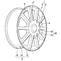
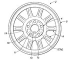
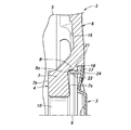
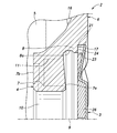
図1は、実施形態に係る車両用ホイール1の斜視図であり、図2及び図3は、ホイール本体2の車軸方向外側及び内側から見た側面図であり、図4は、ホイール本体2を車両に取り付けた状態を示す断面図である。図1〜図4に示すように、車両用ホイール1は、ホイール本体2と、ホイール本体2の車軸方向外側における中心部に着脱可能に取り付けられるキャップ3とを備える。ホイール本体2は、車軸を中心とした円盤状をなすディスク部4と、タイヤが取り付けられるべき円環状をなすリム部5と、ディスク部4及びリム部5を互いに結合する複数本のスポーク部6を備える。
FIG. 1 is a perspective view of a
ディスク部4は、側面視で略円形をなす底壁7と、底壁7の外周縁から車軸方向の外方に延出する周壁8とを備え、底壁7の車軸方向の外側の面である底面7aと周壁8の内周面8aとによって画成される凹部9を有する。底壁7には、側面視における中心を貫通するセンター孔10と、センター孔10よりも半径方向の外方において車軸方向に貫通する複数の締結孔11とが設けられている。複数の締結孔11は、センター孔10と同心である共通の円周上に、周方向において互いに等間隔に配置される。車両本体のハブ12の軸部がセンター孔10に嵌合し、ハブ12に設けられたボルト(図示せず)が締結孔11に挿通されてナット(図示せず)に締結されることにより、又は、ボルト(図示せず)を締結孔11に挿通してハブ12に設けられたナット部(図示せず)に締結させることにより、ホイール本体2がハブ12に固定される。
The
底壁7の車軸方向の内側のハブ取付面7bは、車軸に略直交する平面である。底面7aは、車軸に直交する面に対して半径方向の内方に向かうほど車軸方向の外方に向かうように傾斜している。すなわち、底壁7の厚さは、車軸を中心とする半径方向において、中心に向かうにつれて厚くなっている。このように底面7aが傾斜していることにより、凹部9の周縁が凹部9の半径方向の内側部分よりも大きい深さを有するため、キャップ3の周縁部を凹部9へ深く差し入れることができ、かつ、ハブ12に固定される部分の厚さが厚くなるため、ホイール本体2の剛性が向上している。また、ハブ取付面7bには、締結孔11の間に肉抜き7cが凹設されている。
The
図5は、車軸を通る面で切ったリム部5の拡大断面図である。リム部5は、車軸方向の外側に位置する第1ビードシート部13と、車軸方向の内側に位置する第2ビードシート部14と、第1ビードシート部13及び第2ビードシート部14の間を連結する中間部15とを備える。第1ビードシート部13及び第2ビードシート部14の半径方向の外側の面にはタイヤのビード(図示せず)が密着する。第1ビードシート部13が中間部15に比べて厚肉になっていることにより、車両用ホイール1が回転する際の振動が低減され、騒音振動性能が向上する。また、第1ビードシート部13の半径方向の内側の面が、中間部15の半径方向の内側の面に滑らかに接続していることにより、走行時に空気の流れが乱されず、空力性能及びブレーキの冷却性能が向上する。
FIG. 5 is an enlarged sectional view of the
図1〜図4に示すように、10本のスポーク部6がディスク部4から半径方向の外方に放射状に延出してリム部5の第1ビードシート部13に連結している。10本のスポーク部6は、車軸を中心に10回対称形に配置される。すなわち、互いに隣り合うスポーク部6の半径方向の延長線がなす角度は等しく36°である。スポーク部6の数を変更してもよく、その場合、スポーク部6の数をn本とすると、n本のスポーク部は、車軸を中心にn回対称形に配置される。スポーク部6の数は偶数であることが好ましく、互いに隣り合うスポーク部6が1組となり、2本1組のスポーク部6の延長線がなす角の2等分線上に締結孔11の中心が配置される。従って、締結孔11の数はn/2個である。スポーク部6が10本であれば締結孔11は5個であり、スポーク部6が8本であれば締結孔11は4個である。このように締結孔11を配置することにより、ホイール本体2に加わる上下方向の荷重を分散することができる。
As shown in FIGS. 1 to 4, ten spoke
各々のスポーク部6は、側面視で、半径方向に延びる中心線に対して左右対称形をなす。スポーク部6の車軸方向の外面はディスク部4の車軸方向の外面より車軸方向の外側に位置する。より詳細には、スポーク部6の車軸方向の外面は、半径方向の内端部において、ディスク部4の周壁8の頂面よりも車軸方向の外側に突出しており、半径方向の外方に向かうにつれてわずかに車軸方向の内方に向かうように傾斜している。このようにスポーク部6が車軸方向の外側に突出することによりスポーク部6とディスク部4との接続剛性が向上する。
Each spoke 6 has a symmetrical shape with respect to a center line extending in the radial direction in a side view. The outer surface of the
各々の前記スポーク部6は、側面視で、半径方向の内端部の幅が外端部の幅よりも大きい等脚台形状をなし、また、各々のスポーク部6の車軸方向の内面には肉抜き部16が凹設されている。肉抜き部16は、半径方向の中心線に沿って形成され、側面視で略長方形なす。スポーク部6は、ディスク部4側よりもリム部5側の方を強度上細くできるので、肉抜き部16の形状を長方形とすることで、強度を確保した上で、軽量化できる。なお、半径方向に直交する横断面で、スポーク部6は、車軸方向も内側の幅が車軸方向の外側の幅よりも大きい等脚台形状をなすことが好ましい。等脚台形状をなすスポーク部6の横断面は、肉抜き部16によって車軸方向の内側の底辺が凹んでいる。
Each of the
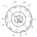
図6は、キャップ3の車軸方向の外側から見た側面図であり、図7及び図8は、それぞれ、図6におけるVII−VII断面図及びVIII−VIII断面図である。図6〜図8に示すように、キャップ3は、側面視で略円形をなし、その半径は、ディスク部4の半径に略一致する。
FIG. 6 is a side view of the
キャップ3の周縁近傍の表面(車軸方向の外側の面)には、凹凸が設けられており、その凸部分がスポーク部6における車軸方向の外側から見える表面を半径方向の内方に延長した形状をなしてスポーク延長部17を形成し、キャップ3の表面の中央側の部分に滑らかに接続している。また、その凹部分は、円弧又は放物線等の湾曲した稜線によってスポーク延長部17の表面及びキャップ3の表面の中央側の部分と区切られたキャップ側連結部18の表面を形成している。また、互いに隣り合うスポーク部6の半径方向の内端部は、表面がスポーク部6よりも車軸方向の内側に凹んだスポーク側連結部19によって連結している。スポーク側連結部19の凹状の表面は、スポーク部6の表面に滑らかに接続している。スポーク側連結部19の凹形状の表面はキャップ側連結部18の凹形状の表面に滑らかに接続しており、キャップ側連結部18とスポーク側連結部19とによって構成される凹状連結部20の表面は、半径方向に延びる中心線に対して側面視で左右対称形をなす。また、凹状連結部20の表面は、水かき状の凹形状、すなわち、半径方向の外側に向かうに従い、周方向の幅が拡がるとともに車軸方向の深さが深くなる凹形状をなすことが好ましい。スポーク部6がスポーク延長部17につながっており、かつ、凹状連結部20の表面が凹形状であるため、スポークが車軸に向かって延長されたように見え、意匠性が向上する。スポーク側連結部19の凹状の表面がスポーク部6の表面に滑らかに接続していることにより、互いに隣り合うスポーク部6に上下方向の力が分散する。
The surface near the periphery of the cap 3 (the outer surface in the axle direction) is provided with irregularities, and the convex portion extends inward in the radial direction from the surface of the
キャップ3の周縁は、スポーク部6及びスポーク側連結部19の半径方向の内端面によって構成されるキャップ合わせ部21に当接する。また、キャップ3は、周縁近傍の裏面(車軸方向の内側の面)から車軸方向の内方に延出して、遊端側が半径方向の外方に膨出した係止部22を有する。係止部22は、半径方向の外方に凹むように形成された周壁8の内周面8aに係止される。さらに、キャップ3の周縁近傍の裏面から車軸方向の内方に突出するように設けられた複数の位置決め部23が、周壁8の頂面(車軸方向外側の面)によって構成された位置合わせ部24に当接する。位置決め部23の突出長さは、係止部22の延出長さよりも短い。キャップ3の周縁がキャップ合わせ部21に当接することにより、キャップ3の半径方向の位置が定まり、係止部22が内周面8aに係止されることにより、キャップ3がホイール本体2に固定され、位置決め部23が位置合わせ部24に当接することにより、キャップ3は車軸方向内側に押されても車軸方向内側に沈み込まず、また、係止部22が内周面8aから車軸方向内側に向かう反力を受け、キャップ3の車軸方向の位置が安定する。また、キャップ3の取付剛性を向上させるため、位置決め部23は、キャップ3内で剛性の高いキャップ側連結部18の近傍に設けられる。
The peripheral edge of the
キャップ3をホイール本体2から取り外すための切欠き部25が、1つのスポーク延長部17の半径方向の外端縁に設けられている。位置決め部23は、キャップ側連結部18の周方向の中央に配置されている箇所と、キャップ側連結部18の周方向の中央からずれて稜線近傍に配置されている箇所がある。ここで、切欠き部25の周方向の両隣にある位置決め部23は、切欠き部25に隣接するキャップ側連結部18の稜線近傍であって、位置決め部23とは周方向における反対側に配置されている。キャップ側連結部18と位置決め部23という比較的剛性の高い部分を側面視で同一箇所に配置すると、キャップ3をホイール本体2に対して安定させるのに好適となる。しかし、切欠き部25にマイナスドライバー等の工具を差し入れてキャップ3をホイール本体2から取り外すには、切欠き部25の周辺が広い範囲に渡って変形することが好ましい。そこで、切欠き部25の周辺では、比較的剛性の高いキャップ側連結部18と位置決め部23とを側面視で重ねるのではなく、周方向に互いにずらして配置することにより、剛性の向上を抑制し、キャップ3の取り外し時に切欠き部25の周辺の広い範囲でキャップ3を変形させられる。
A
また、係止部22の内の1つは、切欠き部25の近傍に、例えば、切欠き部25の半径方向の内側に設けられる。このため、キャップ3の取り外しのために工具を挿入した際、係止部22を直接押すことができて取り外しが容易となる。また、係止部22は周辺に比べて剛性が高いため、工具による取り外しがしやすい。また、切欠き部25は複数のスポーク延長部17に設けてもよいが、切欠き部25を1箇所にのみ設ける場合は、係止部22の1つは、切欠き部25の近傍に配置され、他の1つは、切欠き部25の半径方向の反対側部分の近傍に配置され、残りの係止部22は、キャップ側連結部18の近傍に配置される。キャップ3を取り外す際に変形させることが必要な切欠き部25及びその半径方向の反対側の部分を除いて、係止部22を面剛性の高いキャップ側連結部18に配置することにより、キャップ3の取り付け剛性が向上する。
One of the locking
係止部22は、偶数個配置されており、係止部22の各々には周方向に180°ずれて配置されたものが存在する。このため、キャップ3をホイール本体2に取り付ける時の側面視での位置ずれが防止される。また、係止部22の各々は、互いに隣り合う2つの位置決め部23の各々と車軸とを通る2つの線がなす角の2等分線上に配置されている。このため、係止部22及び位置決め部23がバランスよく配置され、正面視での位置ずれが防止される。
An even number of the locking
位置決め部23は偶数個配置されており、位置決め部23の各々には周方向に180°ずれて配置されたものが存在する。位置決め部23は、互いの周方向間隔が略一定である。キャップ3の裏面には、位置決め部23の各々から半径方向の内方に向かって延出する補強リブ26が設けられている。位置決め部23が車軸に対し回転対称形に配置され、補強リブ26によってキャップ3の剛性が向上するため、キャップ3の車軸方向のガタツキや、ホイール本体2の表面とキャップ3の表面とが互いに車軸方向にずれることを防止できる。
An even number of the
以上のように、ディスク部4よりもスポーク部6を車軸方向の外方に突出させることにより、ホイール本体2の剛性が向上し、ホイール本体2及びキャップ3の表面を連続形状として凹状連結部20を設けることにより、スポークが長くなったように見えて意匠性が向上する。
As described above, the rigidity of the
以上で具体的実施形態の説明を終えるが、本発明は上記実施形態に限定されることなく幅広く変形実施することができる。凹部は、側面視で円形ではなく正多角形のような他の形状としてもよい。 Although the description of the specific embodiments has been completed above, the present invention can be widely modified without being limited to the above embodiments. The concave portion may have another shape such as a regular polygon instead of a circular shape in a side view.
1:車両用ホイール
2:ホイール本体
3:キャップ
4:ディスク部
5:リム部
6:スポーク部
7:底壁
8:周壁
9:凹部
10:センター孔
11:締結孔
12:ハブ
13:第1ビードシート部
14:第2ビードシート部
15:中間部
16:肉抜き部
17:スポーク延長部
18:キャップ側連結部
19:スポーク側連結部
20:凹状連結部
21:キャップ合わせ部
22:係止部
23:位置決め部
24:位置合わせ部
25:切欠き部
26:補強リブ
1: vehicle wheel 2: wheel body 3: cap 4: disk portion 5: rim portion 6: spoke portion 7: bottom wall 8: peripheral wall 9: concave portion 10: center hole 11: fastening hole 12: hub 13: first bead. Seat portion 14: Second bead seat portion 15: Intermediate portion 16: Lightening portion 17: Spoke extension portion 18: Cap-side connection portion 19: Spoke-side connection portion 20: Recessed connection portion 21: Cap mating portion 22: Locking portion 23: positioning part 24: positioning part 25: notch part 26: reinforcing rib
Claims (13)
タイヤが取り付けられるべき円環状をなすリム部と、
前記ディスク部及び前記リム部を互いに結合する複数のスポーク部と、
前記ディスク部の前記凹部を覆うべく、前記ディスク部に取り付けられたキャップとを備える車両用ホイールであって、
互いに隣り合う前記スポーク部が、半径方向の内端側にて、前記車軸方向の外方に向く凹面を有するスポーク側連結部により互いに連結され、
前記キャップが、前記スポーク部を前記半径方向の内方に延長した形状をなす複数のスポーク延長部を備え、
互いに隣り合う前記スポーク延長部間が、対応する前記スポーク側連結部に連続する前記車軸方向の外方を向く凹面を有するキャップ側連結部をなすことを特徴とする車両用ホイール。 A disk portion to be attached to a hub, which has a disk shape centered on the axle, and has a recess formed at the center toward the inside in the axle direction and a plurality of fastening holes formed through the bottom wall of the recess. When,
An annular rim to which the tire should be attached,
A plurality of spokes that couple the disk and the rim together;
A vehicle wheel comprising: a cap attached to the disc portion so as to cover the concave portion of the disc portion,
The spoke portions adjacent to each other are connected to each other by a spoke-side connection portion having a concave surface facing outward in the axle direction on the inner end side in the radial direction,
The cap includes a plurality of spoke extensions having a shape obtained by extending the spoke portion inward in the radial direction,
The vehicle wheel according to claim 1, wherein the spoke extension portions adjacent to each other form a cap-side connection portion having a concave surface facing outward in the axle direction that is continuous with the corresponding spoke-side connection portion.
前記凹部の周縁は、前記凹部の前記半径方向の内側部分よりも大きい深さを有することを特徴とする車両用ホイール。 The vehicle wheel according to claim 1,
The vehicle wheel according to claim 1, wherein a peripheral edge of the concave portion has a greater depth than an inner portion of the concave portion in the radial direction.
前記キャップは、裏面側に設けられて前記凹部の内周面に係止する複数の係止部と、裏面側における前記キャップ側連結部の近傍に設けられて前記内周面を画成する周壁の前記車軸方向の外側の面に当接する複数の位置決め部とを備え、
前記スポーク部の前記半径方向の内端面は、前記キャップの外周縁が当接するキャップ合わせ部を構成することを特徴とする車両用ホイール。 The vehicle wheel according to claim 2,
A plurality of locking portions provided on the back surface side for locking to the inner peripheral surface of the concave portion; and a peripheral wall provided near the cap-side connecting portion on the rear surface side to define the inner peripheral surface. A plurality of positioning portions that abut against the outer surface in the axle direction,
The vehicle wheel according to claim 1, wherein the inner end surface of the spoke portion in the radial direction forms a cap mating portion with which an outer peripheral edge of the cap abuts.
前記キャップを前記ディスク部から取り外すための切欠き部が、少なくとも1つの前記スポーク延長部の前記半径方向の外端縁に設けられ、
前記位置決め部は、前記キャップ側連結部の周方向中央に配置されている箇所と、前記キャップ側連結部の稜線近傍に配置されている箇所があり、前記切欠き部の周方向の両隣にある、前記位置決め部は前記稜線近傍に配置されていることを特徴とする車両用ホイール。 The vehicle wheel according to claim 3,
A notch for removing the cap from the disc portion is provided at the radially outer edge of at least one of the spoke extensions;
The positioning portion has a portion disposed in the center in the circumferential direction of the cap-side connecting portion and a portion disposed near the ridgeline of the cap-side connecting portion, and is located on both sides in the circumferential direction of the cutout portion. The vehicle wheel, wherein the positioning portion is disposed near the ridge line.
前記キャップを前記ディスク部から取り外すための切欠き部が、少なくとも1つの前記スポーク延長部の前記半径方向の外端縁に設けられ、
前記係止部の少なくとも1つは、前記切欠き部の近傍に設けられたことを特徴とする車両用ホイール。 The vehicle wheel according to claim 3,
A notch for removing the cap from the disc portion is provided at the radially outer edge of at least one of the spoke extensions;
A vehicle wheel, wherein at least one of the locking portions is provided near the notch.
前記切欠き部は、1箇所にのみ設けられ、
前記係止部は、前記キャップの裏面に複数配置されており、
前記係止部の各々は、前記切欠き部の近傍と、前記切欠き部から周方向に180°ずれた位置の近傍とに配置されたものを除き、前記キャップ側連結部の近傍に配置されていることを特徴とする車両用ホイール。 The vehicle wheel according to claim 5,
The notch is provided only in one place,
The plurality of locking portions are arranged on the back surface of the cap,
Each of the locking portions is arranged near the cap-side connecting portion, except for those arranged near the notch portion and near a position shifted by 180 ° in the circumferential direction from the notch portion. A vehicle wheel.
前記位置決め部は偶数個配置されており、前記位置決め部の各々には周方向に180°ずれて配置されたものが存在し、
前記位置決め部は、互いの周方向間隔が略一定であり、
前記キャップの裏面には、前記位置決め部の各々から前記半径方向の内方に向かって延出する補強リブが設けられていることを特徴とする車両用ホイール。 The vehicle wheel according to any one of claims 3 to 6,
An even number of the positioning portions are arranged, and each of the positioning portions includes one that is arranged to be shifted by 180 ° in the circumferential direction,
The positioning portion has a substantially constant circumferential interval between each other,
A vehicle wheel, wherein a reinforcing rib is provided on a rear surface of the cap to extend inward in the radial direction from each of the positioning portions.
前記係止部は、偶数個配置されており、前記係止部の各々には周方向に180°ずれて配置されたものが存在し、
前記係止部の各々は、互いに隣り合う2つの前記位置決め部の各々と前記車軸とを通る2つの線がなす角の2等分線上に配置されていることを特徴とする車両用ホイール。 The vehicle wheel according to any one of claims 3 to 7,
An even number of the locking portions are arranged, and each of the locking portions includes one that is arranged to be shifted by 180 ° in the circumferential direction.
A vehicle wheel, wherein each of the locking portions is disposed on a bisector of an angle formed by two lines passing through each of the two positioning portions adjacent to each other and the axle.
前記スポーク部は、側面視で前記車軸から前記リム部に向かって放射状に延び、
前記スポーク側連結部の表面は、前記スポーク部の表面に滑らかに接続しており、
前記締結孔は、それぞれ互いに隣り合う前記スポーク部の延長線がなす角の2等分線上に位置することを特徴とする車両用ホイール。 The vehicle wheel according to any one of claims 1 to 8,
The spoke portion radially extends from the axle toward the rim portion in a side view,
The surface of the spoke-side connecting portion is smoothly connected to the surface of the spoke portion,
The vehicle wheel according to claim 1, wherein the fastening holes are located on bisectors of angles formed by extensions of the spoke portions adjacent to each other.
前記スポーク部は、その数をnとして前記車軸を中心にn回対称形に配置され、
前記スポーク部の各々は、前記半径方向に延びる中心線に対して側面視で左右対称形であり、
前記締結孔及び前記スポーク部は、それぞれ、5個及び10本、又は、4個及び8本配置されたことを特徴とする車両用ホイール。 The vehicle wheel according to claim 9,
The spokes are arranged symmetrically n times around the axle, where n is the number of the spokes,
Each of the spoke portions is bilaterally symmetrical in a side view with respect to the center line extending in the radial direction,
The vehicle wheel according to claim 1, wherein the number of the fastening holes and the number of the spokes are five and ten, or four and eight, respectively.
前記スポーク部は、側面視で、前記半径方向の内端部の幅が前記半径方向の外端部の幅よりも大きい略台形状をなし、
前記スポーク部の前記車軸方向の内側の面には、前記半径方向の中心線に沿って形成され、側面視で略長方形をなす肉抜き部が形成されていることを特徴とする車両用ホイール。 The vehicle wheel according to any one of claims 1 to 10,
The spoke portion has, in a side view, a substantially trapezoidal shape in which the width of the inner end in the radial direction is larger than the width of the outer end in the radial direction,
A wheel for a vehicle, wherein a lightening portion formed along the center line in the radial direction and having a substantially rectangular shape in a side view is formed on an inner surface of the spoke portion in the axle direction.
前記リム部は、前記車軸方向の外側に位置する第1ビードシート部と、前記車軸方向の内側に位置する第2ビードシート部と、前記第1ビードシート部及び前記第2ビードシート部を連結する中間部とを有し、前記第1ビードシート部が、前記中間部よりも厚肉であることを特徴とする車両用ホイール。 The vehicle wheel according to any one of claims 1 to 11, wherein the rim portion includes a first bead seat portion located outside the axle direction and a second bead seat portion located inside the axle direction. And an intermediate portion connecting the first bead seat portion and the second bead seat portion, wherein the first bead seat portion is thicker than the intermediate portion. .
前記リム部の前記半径方向の内側の表面において、前記第1ビードシート部は、前記中間部に滑らかに接続していることを特徴とする車両用ホイール。 13. The vehicle wheel according to claim 12, wherein the first bead seat portion is smoothly connected to the intermediate portion on the radially inner surface of the rim portion.
Priority Applications (2)
| Application Number | Priority Date | Filing Date | Title |
|---|---|---|---|
| JP2018159611A JP6622365B1 (en) | 2018-08-28 | 2018-08-28 | Vehicle wheel |
| CN201910565741.7A CN110861443A (en) | 2018-08-28 | 2019-06-27 | Vehicle wheel |
Applications Claiming Priority (1)
| Application Number | Priority Date | Filing Date | Title |
|---|---|---|---|
| JP2018159611A JP6622365B1 (en) | 2018-08-28 | 2018-08-28 | Vehicle wheel |
Publications (2)
| Publication Number | Publication Date |
|---|---|
| JP6622365B1 JP6622365B1 (en) | 2019-12-18 |
| JP2020032811A true JP2020032811A (en) | 2020-03-05 |
Family
ID=68917222
Family Applications (1)
| Application Number | Title | Priority Date | Filing Date |
|---|---|---|---|
| JP2018159611A Active JP6622365B1 (en) | 2018-08-28 | 2018-08-28 | Vehicle wheel |
Country Status (2)
| Country | Link |
|---|---|
| JP (1) | JP6622365B1 (en) |
| CN (1) | CN110861443A (en) |
Citations (3)
| Publication number | Priority date | Publication date | Assignee | Title |
|---|---|---|---|---|
| JPH03110901U (en) * | 1990-02-28 | 1991-11-13 | ||
| JP3189687U (en) * | 2014-01-10 | 2014-03-27 | 株式会社レイズ | Wheel center boss |
| US20170058994A1 (en) * | 2015-09-02 | 2017-03-02 | Man Hee LIM | Automobile wheel having vibration damping function |
Family Cites Families (6)
| Publication number | Priority date | Publication date | Assignee | Title |
|---|---|---|---|---|
| JP2006199295A (en) * | 2001-09-13 | 2006-08-03 | Topy Ind Ltd | Decorative lightweight alloy wheel |
| JP2005067298A (en) * | 2003-08-21 | 2005-03-17 | Hashimoto Forming Ind Co Ltd | Mounting structure of hubcap for vehicle |
| US20060082213A1 (en) * | 2004-10-14 | 2006-04-20 | Mark Tirado | Vehicle wheel having a reflecting rim |
| JP4091093B2 (en) * | 2006-02-03 | 2008-05-28 | 豊田合成株式会社 | Vehicle wheel |
| JP5337176B2 (en) * | 2011-02-02 | 2013-11-06 | 株式会社モルテン | Wheel cap |
| KR20170027492A (en) * | 2015-09-02 | 2017-03-10 | 임만희 | Anti-vibration of wheel for vehicles |
-
2018
- 2018-08-28 JP JP2018159611A patent/JP6622365B1/en active Active
-
2019
- 2019-06-27 CN CN201910565741.7A patent/CN110861443A/en active Pending
Patent Citations (3)
| Publication number | Priority date | Publication date | Assignee | Title |
|---|---|---|---|---|
| JPH03110901U (en) * | 1990-02-28 | 1991-11-13 | ||
| JP3189687U (en) * | 2014-01-10 | 2014-03-27 | 株式会社レイズ | Wheel center boss |
| US20170058994A1 (en) * | 2015-09-02 | 2017-03-02 | Man Hee LIM | Automobile wheel having vibration damping function |
Also Published As
| Publication number | Publication date |
|---|---|
| CN110861443A (en) | 2020-03-06 |
| JP6622365B1 (en) | 2019-12-18 |
Similar Documents
| Publication | Publication Date | Title |
|---|---|---|
| JP5419989B2 (en) | Wheel disc for automobile | |
| JP4669064B2 (en) | Wheel disc for automobile | |
| JP7042798B2 (en) | Vehicle wheel discs, vehicle wheels including such wheel discs, and methods of producing such wheel discs and vehicle wheels. | |
| JP6125998B2 (en) | Wheel disc for vehicle | |
| US20080277998A1 (en) | Wheel rim | |
| WO2013160999A1 (en) | Automobile wheel | |
| KR20150119840A (en) | Vehicle wheel for passenger cars | |
| JP2019503932A5 (en) | Assembled vehicle wheel | |
| JP6475164B2 (en) | Vehicle wheel for passenger cars | |
| JP2010132278A (en) | Automobile wheel | |
| CN111196109A (en) | Vehicle wheel | |
| CN110861441B (en) | Wheels and vehicles with such wheels | |
| US20190070894A1 (en) | Vehicle wheel | |
| JP6622365B1 (en) | Vehicle wheel | |
| JP6359742B1 (en) | Vehicle wheel disc and vehicle disc wheel | |
| US6443532B1 (en) | Spoked wheel assembly for a bicycle | |
| JP2009119955A (en) | Wheel cap and wheel assembly including the wheel cap | |
| JP2020104816A (en) | Vehicular wheel | |
| JP2020111256A (en) | Vehicular tire wheel assembly | |
| JP7389050B2 (en) | Manufactured vehicle wheel with wheel disc having lightweight pockets | |
| JP2021006424A (en) | Vehicular wheel | |
| US8746518B2 (en) | Spacer for spacing wheel rim from compartment floor | |
| US10864771B2 (en) | Vehicle wheel | |
| JP7632028B2 (en) | Airless tires | |
| JP7366679B2 (en) | steel wheels for vehicles |
Legal Events
| Date | Code | Title | Description |
|---|---|---|---|
| A621 | Written request for application examination |
Free format text: JAPANESE INTERMEDIATE CODE: A621 Effective date: 20190327 |
|
| A977 | Report on retrieval |
Free format text: JAPANESE INTERMEDIATE CODE: A971007 Effective date: 20191112 |
|
| TRDD | Decision of grant or rejection written | ||
| A01 | Written decision to grant a patent or to grant a registration (utility model) |
Free format text: JAPANESE INTERMEDIATE CODE: A01 Effective date: 20191119 |
|
| A61 | First payment of annual fees (during grant procedure) |
Free format text: JAPANESE INTERMEDIATE CODE: A61 Effective date: 20191121 |
|
| R150 | Certificate of patent or registration of utility model |
Ref document number: 6622365 Country of ref document: JP Free format text: JAPANESE INTERMEDIATE CODE: R150 |