JP2020036718A - Biometric sensor - Google Patents
Biometric sensor Download PDFInfo
- Publication number
- JP2020036718A JP2020036718A JP2018164918A JP2018164918A JP2020036718A JP 2020036718 A JP2020036718 A JP 2020036718A JP 2018164918 A JP2018164918 A JP 2018164918A JP 2018164918 A JP2018164918 A JP 2018164918A JP 2020036718 A JP2020036718 A JP 2020036718A
- Authority
- JP
- Japan
- Prior art keywords
- piezoelectric element
- spacer
- piezoelectric
- covering member
- back surface
- Prior art date
- Legal status (The legal status is an assumption and is not a legal conclusion. Google has not performed a legal analysis and makes no representation as to the accuracy of the status listed.)
- Pending
Links
- 125000006850 spacer group Chemical group 0.000 claims abstract description 85
- 230000035945 sensitivity Effects 0.000 abstract description 21
- 239000010410 layer Substances 0.000 description 31
- 239000000463 material Substances 0.000 description 14
- 238000010030 laminating Methods 0.000 description 12
- 238000000034 method Methods 0.000 description 9
- -1 for example Substances 0.000 description 8
- 239000010408 film Substances 0.000 description 5
- 238000003475 lamination Methods 0.000 description 5
- 229910052751 metal Inorganic materials 0.000 description 5
- 239000002184 metal Substances 0.000 description 5
- 229920000139 polyethylene terephthalate Polymers 0.000 description 5
- 239000005020 polyethylene terephthalate Substances 0.000 description 5
- PXHVJJICTQNCMI-UHFFFAOYSA-N Nickel Chemical compound [Ni] PXHVJJICTQNCMI-UHFFFAOYSA-N 0.000 description 4
- 239000004698 Polyethylene Substances 0.000 description 4
- 239000004743 Polypropylene Substances 0.000 description 4
- 239000000853 adhesive Substances 0.000 description 4
- 230000001070 adhesive effect Effects 0.000 description 4
- 238000004519 manufacturing process Methods 0.000 description 4
- 229920000573 polyethylene Polymers 0.000 description 4
- 229920000642 polymer Polymers 0.000 description 4
- 229920001155 polypropylene Polymers 0.000 description 4
- 239000011148 porous material Substances 0.000 description 4
- RYGMFSIKBFXOCR-UHFFFAOYSA-N Copper Chemical compound [Cu] RYGMFSIKBFXOCR-UHFFFAOYSA-N 0.000 description 3
- 241001465754 Metazoa Species 0.000 description 3
- 238000000576 coating method Methods 0.000 description 3
- 229910052802 copper Inorganic materials 0.000 description 3
- 239000010949 copper Substances 0.000 description 3
- 238000001514 detection method Methods 0.000 description 3
- OKTJSMMVPCPJKN-UHFFFAOYSA-N Carbon Chemical compound [C] OKTJSMMVPCPJKN-UHFFFAOYSA-N 0.000 description 2
- 239000002033 PVDF binder Substances 0.000 description 2
- 239000004642 Polyimide Substances 0.000 description 2
- BQCADISMDOOEFD-UHFFFAOYSA-N Silver Chemical compound [Ag] BQCADISMDOOEFD-UHFFFAOYSA-N 0.000 description 2
- 229910052782 aluminium Inorganic materials 0.000 description 2
- XAGFODPZIPBFFR-UHFFFAOYSA-N aluminium Chemical compound [Al] XAGFODPZIPBFFR-UHFFFAOYSA-N 0.000 description 2
- 230000005540 biological transmission Effects 0.000 description 2
- 229910052799 carbon Inorganic materials 0.000 description 2
- 239000011248 coating agent Substances 0.000 description 2
- 229920001577 copolymer Polymers 0.000 description 2
- 239000000945 filler Substances 0.000 description 2
- 229910052759 nickel Inorganic materials 0.000 description 2
- 229920001230 polyarylate Polymers 0.000 description 2
- 229920001721 polyimide Polymers 0.000 description 2
- 229920001343 polytetrafluoroethylene Polymers 0.000 description 2
- 239000004810 polytetrafluoroethylene Substances 0.000 description 2
- 229920002981 polyvinylidene fluoride Polymers 0.000 description 2
- 229920002050 silicone resin Polymers 0.000 description 2
- 229910052709 silver Inorganic materials 0.000 description 2
- 239000004332 silver Substances 0.000 description 2
- 239000010409 thin film Substances 0.000 description 2
- 208000037656 Respiratory Sounds Diseases 0.000 description 1
- NIXOWILDQLNWCW-UHFFFAOYSA-N acrylic acid group Chemical group C(C=C)(=O)O NIXOWILDQLNWCW-UHFFFAOYSA-N 0.000 description 1
- 230000002238 attenuated effect Effects 0.000 description 1
- 230000015572 biosynthetic process Effects 0.000 description 1
- 230000017531 blood circulation Effects 0.000 description 1
- 210000004204 blood vessel Anatomy 0.000 description 1
- 239000011247 coating layer Substances 0.000 description 1
- 239000004020 conductor Substances 0.000 description 1
- 238000012790 confirmation Methods 0.000 description 1
- 238000003745 diagnosis Methods 0.000 description 1
- 238000006073 displacement reaction Methods 0.000 description 1
- 238000001035 drying Methods 0.000 description 1
- 239000000835 fiber Substances 0.000 description 1
- 229910010272 inorganic material Inorganic materials 0.000 description 1
- 239000011147 inorganic material Substances 0.000 description 1
- HFGPZNIAWCZYJU-UHFFFAOYSA-N lead zirconate titanate Chemical compound [O-2].[O-2].[O-2].[O-2].[O-2].[Ti+4].[Zr+4].[Pb+2] HFGPZNIAWCZYJU-UHFFFAOYSA-N 0.000 description 1
- 229910052451 lead zirconate titanate Inorganic materials 0.000 description 1
- 238000005259 measurement Methods 0.000 description 1
- VNWKTOKETHGBQD-UHFFFAOYSA-N methane Chemical compound C VNWKTOKETHGBQD-UHFFFAOYSA-N 0.000 description 1
- 239000004745 nonwoven fabric Substances 0.000 description 1
- 239000003973 paint Substances 0.000 description 1
- 230000003071 parasitic effect Effects 0.000 description 1
- 239000011112 polyethylene naphthalate Substances 0.000 description 1
- 239000000758 substrate Substances 0.000 description 1
- 238000007740 vapor deposition Methods 0.000 description 1
- 239000002759 woven fabric Substances 0.000 description 1
Images


Classifications
-
- H—ELECTRICITY
- H10—SEMICONDUCTOR DEVICES; ELECTRIC SOLID-STATE DEVICES NOT OTHERWISE PROVIDED FOR
- H10N—ELECTRIC SOLID-STATE DEVICES NOT OTHERWISE PROVIDED FOR
- H10N30/00—Piezoelectric or electrostrictive devices
- H10N30/80—Constructional details
- H10N30/88—Mounts; Supports; Enclosures; Casings
-
- A—HUMAN NECESSITIES
- A61—MEDICAL OR VETERINARY SCIENCE; HYGIENE
- A61B—DIAGNOSIS; SURGERY; IDENTIFICATION
- A61B5/00—Measuring for diagnostic purposes; Identification of persons
-
- H—ELECTRICITY
- H10—SEMICONDUCTOR DEVICES; ELECTRIC SOLID-STATE DEVICES NOT OTHERWISE PROVIDED FOR
- H10N—ELECTRIC SOLID-STATE DEVICES NOT OTHERWISE PROVIDED FOR
- H10N30/00—Piezoelectric or electrostrictive devices
- H10N30/30—Piezoelectric or electrostrictive devices with mechanical input and electrical output, e.g. functioning as generators or sensors
- H10N30/302—Sensors
-
- H—ELECTRICITY
- H10—SEMICONDUCTOR DEVICES; ELECTRIC SOLID-STATE DEVICES NOT OTHERWISE PROVIDED FOR
- H10N—ELECTRIC SOLID-STATE DEVICES NOT OTHERWISE PROVIDED FOR
- H10N30/00—Piezoelectric or electrostrictive devices
- H10N30/80—Constructional details
- H10N30/85—Piezoelectric or electrostrictive active materials
- H10N30/857—Macromolecular compositions
-
- H—ELECTRICITY
- H10—SEMICONDUCTOR DEVICES; ELECTRIC SOLID-STATE DEVICES NOT OTHERWISE PROVIDED FOR
- H10N—ELECTRIC SOLID-STATE DEVICES NOT OTHERWISE PROVIDED FOR
- H10N30/00—Piezoelectric or electrostrictive devices
- H10N30/80—Constructional details
- H10N30/87—Electrodes or interconnections, e.g. leads or terminals
- H10N30/875—Further connection or lead arrangements, e.g. flexible wiring boards, terminal pins
-
- H—ELECTRICITY
- H10—SEMICONDUCTOR DEVICES; ELECTRIC SOLID-STATE DEVICES NOT OTHERWISE PROVIDED FOR
- H10N—ELECTRIC SOLID-STATE DEVICES NOT OTHERWISE PROVIDED FOR
- H10N30/00—Piezoelectric or electrostrictive devices
- H10N30/80—Constructional details
- H10N30/88—Mounts; Supports; Enclosures; Casings
- H10N30/883—Additional insulation means preventing electrical, physical or chemical damage, e.g. protective coatings
-
- A—HUMAN NECESSITIES
- A61—MEDICAL OR VETERINARY SCIENCE; HYGIENE
- A61B—DIAGNOSIS; SURGERY; IDENTIFICATION
- A61B2560/00—Constructional details of operational features of apparatus; Accessories for medical measuring apparatus
- A61B2560/04—Constructional details of apparatus
- A61B2560/0443—Modular apparatus
-
- A—HUMAN NECESSITIES
- A61—MEDICAL OR VETERINARY SCIENCE; HYGIENE
- A61B—DIAGNOSIS; SURGERY; IDENTIFICATION
- A61B2562/00—Details of sensors; Constructional details of sensor housings or probes; Accessories for sensors
- A61B2562/02—Details of sensors specially adapted for in-vivo measurements
- A61B2562/0204—Acoustic sensors
-
- A—HUMAN NECESSITIES
- A61—MEDICAL OR VETERINARY SCIENCE; HYGIENE
- A61B—DIAGNOSIS; SURGERY; IDENTIFICATION
- A61B7/00—Instruments for auscultation
-
- A—HUMAN NECESSITIES
- A61—MEDICAL OR VETERINARY SCIENCE; HYGIENE
- A61B—DIAGNOSIS; SURGERY; IDENTIFICATION
- A61B7/00—Instruments for auscultation
- A61B7/003—Detecting lung or respiration noise
-
- A—HUMAN NECESSITIES
- A61—MEDICAL OR VETERINARY SCIENCE; HYGIENE
- A61B—DIAGNOSIS; SURGERY; IDENTIFICATION
- A61B8/00—Diagnosis using ultrasonic, sonic or infrasonic waves
- A61B8/02—Measuring pulse or heart rate
-
- A—HUMAN NECESSITIES
- A61—MEDICAL OR VETERINARY SCIENCE; HYGIENE
- A61B—DIAGNOSIS; SURGERY; IDENTIFICATION
- A61B8/00—Diagnosis using ultrasonic, sonic or infrasonic waves
- A61B8/44—Constructional features of the ultrasonic, sonic or infrasonic diagnostic device
- A61B8/4427—Device being portable or laptop-like
Landscapes
- Life Sciences & Earth Sciences (AREA)
- Health & Medical Sciences (AREA)
- General Health & Medical Sciences (AREA)
- Animal Behavior & Ethology (AREA)
- Veterinary Medicine (AREA)
- Engineering & Computer Science (AREA)
- Biomedical Technology (AREA)
- Heart & Thoracic Surgery (AREA)
- Medical Informatics (AREA)
- Molecular Biology (AREA)
- Surgery (AREA)
- Public Health (AREA)
- Physics & Mathematics (AREA)
- Biophysics (AREA)
- Pathology (AREA)
- Spectroscopy & Molecular Physics (AREA)
- Measuring Pulse, Heart Rate, Blood Pressure Or Blood Flow (AREA)
- Investigating Or Analyzing Materials By The Use Of Ultrasonic Waves (AREA)
- Measuring And Recording Apparatus For Diagnosis (AREA)
Abstract
Description
本発明は、生体センサに関する。 The present invention relates to a biological sensor.
例えば心拍、脈波、血流音、呼吸音等の生体の内部で発生する振動(可聴域の音波振動に限定されず、非可聴域の低周波振動や超音波振動を含む)を測定又は観測することによって、例えば診断、健康管理等を行うことができる。 For example, measuring or observing vibrations generated inside the living body such as heartbeat, pulse wave, blood flow sound, respiratory sound, etc. (not limited to audible sound wave vibrations, including non-audible low frequency vibrations and ultrasonic vibrations) By doing so, for example, diagnosis, health management, and the like can be performed.
生体の振動を検出する生体センサとしては、例えば圧電素子を用いた振動波形センサが公知である(国際公開第2017/187710号公報参照)。この公知の振動波形センサは、基材上に実装された圧電素子、この圧電素子の回りに配設されるスペーサ及び圧電素子を覆う被覆部を有し、このスペーサ等で囲まれた領域に例えばシリコン樹脂を充填して構成されている。この従来の生体センサ(振動波形センサ)では、被覆部側を生体に当てることで生体の振動を検出する。 As a living body sensor for detecting vibration of a living body, for example, a vibration waveform sensor using a piezoelectric element is known (see International Publication No. WO2017 / 187710). This known vibration waveform sensor includes a piezoelectric element mounted on a base material, a spacer disposed around the piezoelectric element, and a covering portion that covers the piezoelectric element. It is configured by filling with silicone resin. In this conventional biological sensor (vibration waveform sensor), the vibration of the living body is detected by applying the covering portion to the living body.
しかしながら、前記従来の生体センサにおいては主にスペーサから基板を介して圧電素子に伝わった振動が検出されるため、伝搬経路が長い。このため、感度が低下し易く、ノイズが混入し易い。また、被測定対象である生体と圧電センサとの間等に被覆部やシリコン樹脂が存在するため、その弾性により振動が減衰し易いうえ、前記スペーサ及び前記被覆部等が圧電素子を密着して取り囲むので、圧電素子の変形が抑制される。この点からも前記従来の生体センサの感度は低下し易い。従って、感度が高く、ノイズ耐性の強い生体センサが求められている。 However, in the above-mentioned conventional biosensor, the propagation path is long because mainly vibration transmitted from the spacer to the piezoelectric element via the substrate is detected. For this reason, the sensitivity is apt to decrease, and noise is likely to be mixed. In addition, since the covering portion and the silicone resin are present between the living body to be measured and the piezoelectric sensor, vibration is easily attenuated by the elasticity thereof, and the spacer and the covering portion adhere to the piezoelectric element in close contact with each other. Since it surrounds, deformation of the piezoelectric element is suppressed. From this point as well, the sensitivity of the conventional biosensor tends to decrease. Therefore, a biosensor having high sensitivity and high noise resistance is required.
前記実情に鑑みて、本発明は、感度が高く、ノイズ耐性の強い生体センサを提供することを課題とする。 In view of the above circumstances, an object of the present invention is to provide a biosensor having high sensitivity and high noise resistance.
前記課題を解決するためになされた本発明の一態様に係る生体センサは、シート状の圧電素子と、平面視で前記圧電素子の周囲に空隙をおいて配設されるスペーサと、前記圧電素子及び前記スペーサの表面側を覆う被覆部材とを備え、前記スペーサが前記被覆部材を裏面側から支持し、前記圧電素子が前記被覆部材に固定されている。 According to one embodiment of the present invention, there is provided a biological sensor including a sheet-shaped piezoelectric element, a spacer disposed with a space around the piezoelectric element in a plan view, and the piezoelectric element. And a covering member for covering the front side of the spacer, wherein the spacer supports the covering member from the back side, and the piezoelectric element is fixed to the covering member.
本発明の一態様に係る生体センサにおいて、前記スペーサの裏面が、前記圧電素子の裏面と平行な平面であるとよい。 In the biosensor according to one embodiment of the present invention, the back surface of the spacer may be a plane parallel to the back surface of the piezoelectric element.
本発明の一態様に係る生体センサは、前記被覆部材と対向するように前記圧電素子の裏面側に配設されるプレートをさらに備えるとよい。 The biosensor according to one aspect of the present invention may further include a plate disposed on the back surface side of the piezoelectric element so as to face the covering member.
本発明の一態様に係る生体センサにおいて、前記プレートの裏面と前記スペーサの裏面とが面一、又は前記プレートの裏面が前記スペーサの裏面より裏面側に突出しているとよい。 In the biosensor according to one embodiment of the present invention, the back surface of the plate and the back surface of the spacer may be flush with each other, or the back surface of the plate may protrude from the back surface of the spacer to the back surface.
本発明の一態様に係る生体センサは、平面視で重なり合わないように配設される複数の前記圧電素子を備えるとよい。 The biosensor according to one embodiment of the present invention may include a plurality of the piezoelectric elements arranged so as not to overlap in a plan view.
なお、本発明において、「裏面側」とは、生体表面と対向して配置される側をいい、「表面側」とは、生体表面と反対に配置される側をいう。 In the present invention, the “back side” refers to a side arranged to face the living body surface, and the “front side” refers to a side arranged opposite to the living body surface.
本発明の一態様に係る生体センサでは、圧電素子が固定された被覆部材がスペーサにより支持されている。このため、当該生体センサでは、圧電素子を生体に接触させて生体の振動を検出することができるので、伝搬経路を短くすることができる。また、当該生体センサは、圧電素子とスペーサとの間に空隙を有する。このため、圧電素子の変形がスペーサ等により抑制され難いので、圧電素子の感度を確保し易い。従って、当該生体センサは、感度が高く、ノイズ耐性に強い。 In the biological sensor according to one embodiment of the present invention, the covering member to which the piezoelectric element is fixed is supported by the spacer. For this reason, in the biological sensor, since the vibration of the living body can be detected by bringing the piezoelectric element into contact with the living body, the propagation path can be shortened. Further, the biosensor has a gap between the piezoelectric element and the spacer. For this reason, since the deformation of the piezoelectric element is hardly suppressed by the spacer or the like, the sensitivity of the piezoelectric element is easily ensured. Therefore, the biological sensor has high sensitivity and high noise resistance.
以下、適宜図面を参照しつつ、本発明の実施の形態を詳説する。 Hereinafter, embodiments of the present invention will be described in detail with reference to the drawings as appropriate.
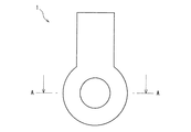
図1及び図2に本発明の一実施形態に係る生体センサ1を示す。当該生体センサ1は、例えば人、動物等の生体の表面に密接して配置され、生体内部の振動、例えば脈波を検出するために用いられる。
1 and 2 show a
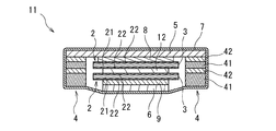
当該生体センサ1は、シート状の圧電素子2と、平面視で圧電素子2の周囲に空隙3をおいて配設されるスペーサ4と、圧電素子2及びスペーサ4の表面側を覆う被覆部材5と、被覆部材5と対向するように圧電素子2の裏面側に配設されるプレート6と、最外部に全体を包むように配設されるシールド層7とを備える。
The
<圧電素子>
圧電素子2は、圧力を電圧に変換する圧電材料から形成され、生体振動の圧力波によって加えられた力による変形を電圧に変換する。圧電素子2は、シート状乃至フィルム状の圧電体21及びこの圧電体21の表裏に積層される一対の電極22を有する。
<Piezoelectric element>
The
(圧電体)
圧電体21を形成する圧電材料としては、例えばチタン酸ジルコン酸鉛等の無機材料であってもよいが、生体の表面に密着できるよう可撓性を有する高分子圧電材料であることが好ましい。また、圧電体21として、高分子圧電材料に多数の気孔を形成した多孔性フィルムを使用することによって、可撓性及び圧電定数を比較的大きくすることができる。
(Piezoelectric)
The piezoelectric material forming the
前記高分子圧電材料としては、例えばポリフッ化ビニリデン(PVDF)、フッ化ビニリデン−3フッ化エチレン共重合体(P(VDF/TrFE))、シアン化ビニリデン−酢酸ビニル共重合体(P(VDCN/VAc))等を挙げることができる。また、これらの高分子圧電材料を多孔性フィルムとすることによって、より可撓性が大きく、圧電定数の大きい圧電素子2を形成することができる。
As the polymer piezoelectric material, for example, polyvinylidene fluoride (PVDF), vinylidene fluoride-ethylene trifluoride copolymer (P (VDF / TrFE)), vinylidene cyanide-vinyl acetate copolymer (P (VDCN / VAc)) and the like. Further, by using these polymer piezoelectric materials as porous films, it is possible to form the
また、圧電体21として、圧電特性を有しない例えばポリテトラフルオロエチレン(PTFE)、ポリプロピレン(PP)、ポリエチレン(PE)、ポリエチレンテレフタレート(PET)等に多数の扁平な気孔を形成し、例えばコロナ放電等によって扁平な気孔の対向面を分極して帯電させることによって圧電特性を付与したものを使用することもできる。
Further, as the
圧電体21の平均厚さの下限としては、10μmが好ましく、50μmがより好ましい。一方、圧電体21の平均厚さの上限としては、500μmが好ましく、200μmがより好ましい。圧電体21の平均厚さが前記下限に満たない場合、圧電素子2の強度が不十分となるおそれがある。逆に、圧電体21の平均厚さが前記上限を超える場合、圧電素子2の変形能が小さくなり、検出感度が不十分となるおそれがある。
The lower limit of the average thickness of the
(電極)
電極22は、圧電体21の両面に積層され、圧電体21の表裏の電位差を検出するために用いられる。
(electrode)
The
電極22の材質としては、導電性を有するものであればよく、例えばアルミニウム、銅、ニッケル等の金属や、カーボン等を挙げることができる。
The material of the
電極22の平均厚さとしては、特に限定されず、積層方法にもよるが、例えば0.1μm以上30μm以下とすることができる。電極22の平均厚さが前記下限に満たない場合、電極6,7の強度が不十分となるおそれがある。逆に、電極22の平均厚さが前記上限を超える場合、圧電体21への振動の伝達を阻害するおそれがある。
The average thickness of the
電極22の圧電体21への積層方法としては、特に限定されず、例えば金属の蒸着、カーボン導電インクの印刷、銀ペーストの塗布乾燥等が挙げられる。
The method for laminating the
電極22は、平面視で複数の領域に分割して形成され、実効的に圧電素子2を複数の圧電素子として機能させるものであってもよい。
The
図2に示す圧電素子2では、端面まで電極22が形成されているが、電極22の形成領域は圧電素子2の端面まで達していなくともよい。つまり、電極22は、圧電体21の表面及び裏面の全面に積層されていてもよいが、電位差が検出できる限り、圧電体21の表面及び裏面の一部に積層されていてもよい。
In the
圧電素子2の平面視形状は、例えば直径2mm以上10mm以下の円形とすることができる。前記直径が前記下限未満であると、例えば脈波を測定する場合であれば圧電素子2が血管を覆うように当該生体センサ1の位置合わせをすることが困難となるおそれがある。逆に前記直径が前記上限を超えると、当該生体センサ1が不要に大きくなり、取扱いが不便になるおそれがある。
The planar shape of the
圧電素子2の表面、つまり圧電素子2の表面側の電極22と被覆部材5との間には信号配線8が配設されている。また、圧電素子2の裏面、つまり圧電素子2の裏面側の電極22とプレート6との間にはグランド配線9が配設されている。
The
この信号配線8及びグランド配線9は、圧電素子2の一対の電極22により検出された電位差を検出回路に伝えるために用いられる。このため、この信号配線8及びグランド配線9は、不図示の検出回路に接続される。
The
信号配線8及びグランド配線9としては、導電性を有するものであればよく、例えばアルミニウム、銅、ニッケル等の金属からなるフィルムや、カーボン等の導電性のある材料を含むフィルム、導電性繊維からなる織物や不織布等を挙げることができる。
The
信号配線8及びグランド配線9の平均厚さとしては、特に限定されず、例えば15μm以上50μm以下とすることができる。信号配線8及びグランド配線9の平均厚さが前記下限未満であると、信号配線8及びグランド配線9の導電性が不十分となるおそれがある。逆に、信号配線8及びグランド配線9の平均厚さが前記上限を超えると、圧電素子2への振動の伝達を阻害するおそれがある。
The average thickness of the
当該生体センサ1は、圧電素子2が後述する被覆部材5に固定されている。つまり、圧電素子2と被覆部材5との間に、例えば圧電素子2を表面側又は裏面側へ付勢するようなバネやゴム等の弾性部材を有さない。このように圧電素子2を被覆部材5に固定することで、生体の振動が弾性部材により吸収されることを抑止できるので、圧電素子2の感度を高めることができる。なお、圧電素子2は、図2に示すように信号配線8を間に挟んで被覆部材5に固定されている。このようにバネやゴム等のような弾性を有しない固定部材を間に介して圧電素子2と被覆部材5を固定することもできる。圧電素子2と被覆部材5との間に挟まれる前記固定部材としては、導電性のフィルム等を用いた導電配線であってもよいし、高さ調整用の部材であってもよい。
In the
<スペーサ>
スペーサ4は、例えば図2に示すように壁41とグランド配線42との積層により構成される。なお、スペーサ4は図2の構成に限定されず、例えば壁41のみにより構成することもできるが、以下図2の構成を例にとり説明する。
<Spacer>
The
スペーサ4の壁41の材質としては、ポリエチレンテレフタレート(PET)、ポリプロピレン(PP)、ポリエチレン(PE)、ポリエチレンナフタレート(PEN)、ポリアリレート(PAR)、ポリイミド(PI)等を挙げることができるが、中でも適度な剛性を有するPETが好ましい。
Examples of the material of the
グランド配線42の材質としては、圧電素子2のグランド配線9と同様とできる。また、グランド配線42は、圧電素子2の表面に配設される信号配線8及び圧電素子2の裏面に配設されるグランド配線9と高さ(当該生体センサ1の表裏方向の位置)が一致するように配設されるとよい。具体的には、スペーサ4のグランド配線42が高さの対応する信号配線8及びグランド配線9と同等の厚さであり、グランド配線42に挟まれる壁41が圧電素子2と同等の厚さであるとよい。このように配設することで、スペーサ4のグランド配線42がシールドとして機能し、圧電素子2が検出する信号にノイズが混入することを抑止できる。また、当該生体センサ1を製造する際に、圧電素子2の信号配線8やグランド配線9と、スペーサ4のグランド配線42とを同層で一度に積層して製造できるので、製造効率を高められる。
The material of the
スペーサ4は、後述する被覆部材5を裏面側から支持する。つまり、被覆部材5は、スペーサ4により位置が固定され、振動することが抑制される。このため、被覆部材5に固定される圧電素子2の感度を高めることができる。
The
スペーサ4は、被覆部材5を支持できる限り圧電素子2の周囲に断続して配設されてもよいが、平面視で圧電素子2の全周を取り囲むように配設されることが好ましい。このようにスペーサ4を平面視で圧電素子2の全周を取り囲むように配設することで、被覆部材5を安定して支持できるので、圧電素子2の感度をさらに高められる。
The
また、スペーサ4の裏面が、圧電素子2の裏面と平行な平面であるとよい。このようにスペーサ4の裏面を圧電素子2の裏面と平行な平面とすることで、当該生体センサ1を生体に接触させた際、スペーサ4の生体への接触面積が大きくなるので、被覆部材5を安定して支持できる。従って、圧電素子2の感度をさらに高められる。
Further, the back surface of the
スペーサ4の高さは、当該生体センサ1の使用時にスペーサ4の裏面が生体と接し被覆部材5を固定可能となる高さとされる。また、スペーサ4の高さは、当該生体センサ1の使用時に圧電素子2が裏面側から振動を検知できるように、つまり圧電素子2、プレート6、シールド層7及び生体が、生体振動の状態に関わらず表面側から裏面側へ向かう方向(以降、「裏面方向」ともいう)に連続するよう調整される。「生体振動の状態に関わらず裏面方向に連続する」とは、例えば圧電素子2が生体振動により圧縮される力を受けた際においても例えばプレート6と圧電素子2との間に空隙が生じたりしないことを意味する。
The height of the
スペーサ4の平均高さの下限としては、300μmが好ましく、400μmがより好ましい。一方、スペーサ4の平均高さの上限としては、800μmが好ましく、700μmがより好ましい。スペーサ4の平均高さが前記下限未満であると、当該生体センサ1を生体に接触させる際、プレート6がスペーサ4の裏面より突出し過ぎてスペーサ4が生体に接触せず、被覆部材5を支持できないおそれがある。逆に、スペーサ4の平均高さが前記上限を超えると、例えばスペーサ4の裏面側での揺れが表面側でスペーサ4の高さを半径として増幅されるため、被覆部材5が振動し易くなるおそれがある。
The lower limit of the average height of the
スペーサ4の裏面の平均幅(径方向の平均幅)は、特に限定されないが、例えば1mm以上5mm以下とできる。スペーサ4の平均幅が前記下限未満であると、当該生体センサ1を生体に接触させた際、スペーサ4の接触面積が小さくなるため、被覆部材5を安定して支持できないおそれがある。逆に、スペーサ4の平均幅が上限を超えると、当該生体センサ1が平面視で不要に大きくなり、取扱いが不便になるおそれがある。
The average width (radial average width) of the back surface of the
スペーサ4は圧電素子2と隣接しており、スペーサ4と圧電素子2との間には空隙3がある。この空隙3は、圧電素子2が変形した際においてもスペーサ4に接触しないだけの大きさがあればよく、空隙3の幅の下限としては、例えば10μmとできる。一方、前記空隙3の幅の上限は、特に限定されないが、当該生体センサ1の取扱性、すなわち小型化の観点から例えば3mmとできる。
The
空隙3には、ゲル等の充填剤は充填されない。このように空隙3に充填剤を充填しないことで、圧電素子2の変形が抑制されないので、圧電センサの感度を確保し易い。
The
<被覆部材>
被覆部材5は、板状であり、上述のように圧電素子2及びスペーサ4の表面側を覆う。被覆部材5が、平面視でスペーサ4の外縁を包含するように圧電素子2及びスペーサ4の表面側を覆ってもよいが、被覆部材5の外縁とスペーサ4の外縁とが一致するように覆うとよい。このように覆うことで、平面視で被覆部材5の大きさを小さくできるので、当該生体センサ1の取扱性が向上する。
<Coating member>
The covering
被覆部材5の材質としては、スペーサ4の壁41と同様とできる。また、被覆部材5は可撓性を有するとよい。このように被覆部材5に一定の可撓性を持たせることで、測定の対象とする生体の表面が曲面であっても当該生体センサ1を適切に接触させることができる。
The material of the covering
被覆部材5の平均厚さの下限としては、50μmが好ましく、100μmがより好ましい。一方、被覆部材5の平均厚さの上限としては、400μmが好ましく、250μmがより好ましい。被覆部材5の平均厚さが前記下限未満であると、被覆部材5が曲がり易くなり過ぎるため、圧電素子2の位置を固定し難くなる。このため、当該生体センサ1の感度が低下するおそれがある。また、被覆部材5の平均厚さが前記下限未満であると、寄生容量が大きくなりノイズが発生し易くなるおそれがある。逆に、被覆部材5の平均厚さが前記上限を超えると、被覆部材5の可撓性が不足し、測定の対象とする生体の表面が曲面である場合に当該生体センサ1を接触させることが困難となるおそれがある。
As a minimum of average thickness of covering
<プレート>
プレート6は、生体の一部で発生し伝わった振動を圧電素子2へプレート6全面の振動として伝える。このように広面積の振動として圧電素子2へ振動を伝えることで、圧電素子2の感度を高められる。
<Plate>
The
当該生体センサ1では、プレート6は、平面視で圧電素子2よりも小さい、つまり圧電素子2が平面視でプレート6の外側に突出している。一方、プレート6は、平面視で圧電素子2よりも大きい、つまりプレート6が平面視で圧電素子2の外側に突出する構成とすることもできる。
In the
また、プレート6が平面視で圧電素子2よりも小さい場合、プレート6は平面視で圧電素子2の電極22よりも小さく、電極22よりも狭い領域で圧電素子2と接することもできる。一方、プレート6は平面視で圧電素子2の電極22よりも大きくすること、つまり電極22よりも広い領域で圧電素子2と接する構成とすることもできる。
When the
プレート6の裏面とスペーサ4の裏面とが面一であるか、プレート6の裏面がスペーサ4の裏面より裏面側に突出しているか、いずれかであるとよい。このようにプレート6を構成することで、スペーサ4の裏面が生体に接触した状態で、圧電素子2が生体からの振動をより確実に受信することができる。
It is preferable that either the back surface of the
プレート6の材質としては、スペーサ4の壁41と同様とできる。プレート6の平面視形状としては、圧電素子2の平面形状と同様であることが好ましい。また、プレート6の平均厚さとしては、被覆部材5と同様とできる。
The material of the
<シールド層>
シールド層7は、上述のように当該生体センサ1の最外部に全体を包むように配設される。つまり、シールド層7は、圧電素子2、スペーサ4、被覆部材5及びプレート6を内包するように配設される。
<Shield layer>
The
シールド層7は、絶縁層と、この絶縁層の表面に積層される導電層とを有する。前記絶縁層としては、例えばアクリルを用いることができる。また、前記導電層は、銀や銅の導電塗料の塗布層とすることができる。このようにシールド層7の裏面を絶縁層とし表面を導電性とすることで、圧電素子2との短絡を抑止しつつ、ノイズをシールドできる。
The
また、シールド層7は可撓性を有するとよい。このようにシールド層7が可撓性を有することで、生体で生じた振動をより確実にプレート6に伝達できる。
Further, the
シールド層7の平均厚さは特に限定されないが、例えば10μm以上100μm以下とできる。シールド層7の平均厚さが前記下限未満であると、使用時にシールド層7が破れ易くなるおそれがある。逆に、シールド層7の平均厚さが前記上限を超えると、シールド層7の可撓性が不足し、当該生体センサ1の感度が低下するおそれがある。
The average thickness of the
<当該生体センサの製造方法>
当該生体センサ1は、例えば信号配線積層工程、圧電素子積層工程、グランド配線積層工程、プレート積層工程及びシールド層被覆工程を備える製造方法により製造することができる。
<Method of manufacturing the biological sensor>
The
(信号配線積層工程)
信号配線積層工程では、被覆部材5の裏面に信号配線8を積層する。具体的には、信号配線8を形取った金属薄膜を接着剤により被覆部材5の裏面に貼り付ける。この際、スペーサ4の表面側のグランド配線42を同時に積層する。
(Signal wiring lamination process)
In the signal wiring laminating step, the
(圧電素子積層工程)
圧電素子積層工程では、信号配線積層工程で積層した信号配線8の裏面に圧電素子2を積層する。具体的には、圧電素子2を接着剤により信号配線8の裏面に貼り付ける。この際、圧電素子2と同じ高さにあるスペーサ4の壁41を同時にグランド配線42に積層する。
(Piezoelectric element lamination process)
In the piezoelectric element stacking step, the
(グランド配線積層工程)
グランド配線積層工程では、圧電素子積層工程で積層した圧電素子2の裏面にグランド配線9を積層する。具体的には、グランド配線9を形取った金属薄膜を接着剤により圧電素子2の裏面に貼り付ける。この際、スペーサ4の裏面側のグランド配線42を同時に壁41に積層する。なお、圧電素子2の裏面に積層されるグランド配線9とスペーサ4のグランド配線42とは同電位であるので、両者は接続されていることが好ましい。
(Ground wiring lamination process)
In the ground wiring laminating step, the
(プレート積層工程)
プレート積層工程では、グランド配線積層工程で積層したグランド配線9の裏面にプレート6を積層する。具体的には、プレート6を接着剤によりグランド配線9の裏面に貼り付ける。この際、プレート6と同じ高さにあるスペーサ4の壁41を同時に積層する。
(Plate lamination process)
In the plate laminating step, the
(シールド層被覆工程)
シールド層被覆工程では、プレート積層工程後の圧電素子2、スペーサ4、被覆部材5及びプレート6を内包するようにシールド層7で被覆する。
(Shield layer coating process)
In the shield layer covering step, the
以上の工程により、当該生体センサ1を製造することができる。なお、前記製造方法では、被覆部材5と信号配線8との間及びグランド配線9とプレート6との間を接着する方法を説明したが、これらの間は接着せず、被覆部材5とプレート6とにより、信号配線8、圧電素子2及びグランド配線9を挟み込む構成としてもよい。このような構成とすることで、接着する場合に比べて圧電素子2の変形が抑制され難いので、圧電素子2の感度を確保し易い。
Through the above steps, the
<当該生体センサの使用方法>
当該生体センサ1は、スペーサ4の裏面が生体に接触するように生体に固定して使用する。
<How to use the biological sensor>
The living
生体への固定位置としては、生体振動が発生している箇所が、平面視で圧電素子2と重なる位置とされる。実際には圧電素子2が一定の大きさを有するので、例えば当該生体センサ1の位置合わせとしては、生体振動が発生していると推定される箇所に、当該生体センサ1を配設し、生体振動が検出できることを確認する方法を用いることができる。なお、生体振動が検出できない場合は、配設位置を変更して確認作業を再度行うとよい。
As a fixed position on the living body, a position where the living body vibration is generated is a position overlapping with the
また、生体への固定位置で、生体が曲面である場合が生じ得るが、このような場合は被覆部材5を曲げることで生体の曲面に追従させるとよい。
In addition, the living body may have a curved surface at the fixed position to the living body. In such a case, the covering
生体への固定方法は特に限定されないが、例えばテープ等により貼り付けることで行える。当該生体センサ1では、スペーサ4により被覆部材5の位置が固定される程度に固定を行えばよい。従って、当該生体センサ1を生体に対して大きな抑え圧で固定する必要はない。
The method of fixing to the living body is not particularly limited, but it can be performed, for example, by attaching with a tape or the like. In the
上述のように固定された当該生体センサ1によれば、生体振動に応じて圧電素子2からの電位変異が観測できる。この電位変位を公知の測定装置により測定することで、生体の振動の大きさや周期等を観測することができる。
According to the
<利点>
当該生体センサ1では、圧電素子2が固定された被覆部材5がスペーサ4により支持されている。このため、当該生体センサ1では、圧電素子2を生体に接触させて生体の振動を検出することができるので、伝搬経路を短くすることができる。また、当該生体センサ1は、圧電素子2とスペーサ4との間に空隙3を有する。このため、圧電素子2の変形がスペーサ4等により抑制され難いので、圧電素子2の感度を確保し易い。従って、当該生体センサ1は、感度が高く、ノイズ耐性に強い。
<Advantages>
In the
[第二実施形態]
図3に本発明の一実施形態に係る生体センサ10を示す。当該生体センサ10は、例えば人、動物等の生体の表面に密接して配置され、生体内部の振動、例えば脈波を検出するために用いられる。
[Second embodiment]
FIG. 3 shows a
当該生体センサ10は、シート状の3つの圧電素子と、平面視で各圧電素子の周囲に空隙をおいて配設されるスペーサと、前記複数の圧電素子及びスペーサの表面側を覆う被覆部材と、前記被覆部材と対向するように前記各圧電素子の裏面側に配設されるプレートと、最外部に全体を包むように配設されるシールド層とを備える。
The
<圧電素子>
前記各圧電素子の平面視形状は、例えば直径2mm以上10mm以下の円形とすることができる。
<Piezoelectric element>
The planar shape of each of the piezoelectric elements may be, for example, a circle having a diameter of 2 mm or more and 10 mm or less.
前記3つの圧電素子は平面視で重なり合わないように配設されている。前記3つの圧電素子の配設位置は特に限定されないが、例えば図3に示すようにその中心が正三角形となるように配設され、その一辺が5mm以上15mm以下とされる。 The three piezoelectric elements are arranged so as not to overlap in plan view. The arrangement positions of the three piezoelectric elements are not particularly limited. For example, as shown in FIG. 3, the three piezoelectric elements are arranged so that their centers are equilateral triangles, and one side thereof has a length of 5 mm or more and 15 mm or less.
また、前記3つの圧電素子は並列に接続されることが好ましい。このように前記3つの圧電素子を並列に接続することで、いずれかの圧電素子が生体の振動を検出すれば、当該生体センサ10が振動を検出できる。このため、当該生体センサ10の位置合わせが容易に行える。
Preferably, the three piezoelectric elements are connected in parallel. By connecting the three piezoelectric elements in parallel in this way, if any one of the piezoelectric elements detects the vibration of the living body, the
前記圧電素子は、上述の平面視形状以外については第一実施形態の圧電素子2と同様に構成できるので、詳細説明を省略する。
Since the piezoelectric element can be configured in the same manner as the
<スペーサ及びプレート>
スペーサ及びプレートは、前記3つの圧電素子それぞれに対して第一実施形態のスペーサ4及びプレート6と同様に構成できるので、詳細説明を省略する。
<Spacer and plate>
Since the spacer and the plate can be configured for each of the three piezoelectric elements in the same manner as the
<被覆部材>
被覆部材は1枚の板状であり、前記3つの圧電素子及びスペーサの表面側を覆う。前記被覆部材は、第一実施形態の被覆部材5と同様に構成できるので、詳細説明を省略する。
<Coating member>
The covering member has a single plate shape and covers the surface sides of the three piezoelectric elements and the spacer. Since the covering member can be configured in the same manner as the covering
<シールド層>
シールド層は、第一実施形態のシールド層7と同様に構成できるので、詳細説明を省略する。
<Shield layer>
Since the shield layer can be configured in the same manner as the
当該生体センサ10は、第一実施形態の生体センサ1と同様に製造及び使用をすることができる。このため詳細説明を省略する。
The
<利点>
当該生体センサ10は、平面視で重なり合わないように配設される複数の圧電素子を備えるので、1つの圧電素子を備える場合に比べて各圧電素子の平面視での面積を小さくすることができる。生体の振動は一箇所で発生するから、この生体振動に接する圧電素子の面積が小さいので、生体振動により圧電素子に発生する面圧を高められる。従って、当該生体センサ10は、生体振動に対する感度を高められる。また、当該生体センサ10は、各圧電素子の平面視での面積が小さいので、生体の測定位置が曲面であっても、その曲面に追従して固定し易い。
<Advantages>
Since the
[その他の実施形態]
前記実施形態は、本発明の構成を限定するものではない。従って、前記実施形態は、本明細書の記載及び技術常識に基づいて前記実施形態各部の構成要素の省略、置換又は追加が可能であり、それらは全て本発明の範囲に属するものと解釈されるべきである。
[Other Embodiments]
The embodiments do not limit the configuration of the present invention. Therefore, in the above-described embodiment, it is possible to omit, replace, or add the components of each part of the embodiment based on the description of the present specification and common technical knowledge, and all of them are interpreted as belonging to the scope of the present invention. Should.
前記実施形態では、当該生体センサがシールド層を備える場合を説明したが、シールド層は必須の構成要件ではなく、省略可能である。 In the above-described embodiment, the case where the biological sensor includes the shield layer has been described. However, the shield layer is not an essential component and can be omitted.
前記実施形態では、当該生体センサがプレートを備える場合を説明したが、プレートは必須の構成要件ではなく、省略可能である。プレートを備えない生体センサにおいては、圧電素子により直接振動を検出する。 In the above-described embodiment, the case where the biosensor includes a plate has been described. However, the plate is not an essential component and can be omitted. In a biological sensor having no plate, vibration is directly detected by a piezoelectric element.
前記実施形態では、スペーサの壁及びグランド配線の平面視での面積が等しい場合を図示しているが、この平面視面積は高さ方向の位置により異なってもよい。 In the above-described embodiment, the case where the area of the spacer wall and the ground wiring is equal in plan view is illustrated, but the area in plan view may be different depending on the position in the height direction.
前期実施形態では、圧電素子の表面に信号配線が配設され、圧電素子の裏面にグランド配線が配設される場合を説明したが、信号配線及びグランド配線は配置が逆、つまり圧電素子の裏面に信号配線が配設され、圧電素子の表面にグランド配線が配設されてもよい。 In the first embodiment, the case where the signal wiring is provided on the front surface of the piezoelectric element and the ground wiring is provided on the rear surface of the piezoelectric element has been described. However, the arrangement of the signal wiring and the ground wiring is reversed, that is, the rear surface of the piezoelectric element is May be provided with a signal wire, and a ground wire may be provided on the surface of the piezoelectric element.
前期第二実施形態では、平面視で重なり合わないように配設されている圧電素子が3つの場合を説明したが、平面視で重なり合わないように配設される圧電素子の数は3に限定されず、2あるいは4以上であってもよい。 In the second embodiment, the case where three piezoelectric elements are arranged so as not to overlap in plan view has been described, but the number of piezoelectric elements arranged so as not to overlap in plan view is three. It is not limited, and may be 2 or 4 or more.
また、図4に示すように、当該生体センサ11が被覆部材5の裏面に積層される複数の圧電素子2(図4では2つの圧電素子2)を備えてもよい。図4に示す当該生体センサ11では、2つの圧電素子2が接続配線12を介して直列に接続されている。このように複数の圧電素子2を直列に積層することで、圧電素子2の感度を高めることができる。
Further, as shown in FIG. 4, the
前記実施形態では、圧電素子の平面視形状として円形である場合を説明したが、圧電素子の平面視形状は円形に限定されるものではない。圧電素子の平面視形状は、例えば楕円形状や、三角形、四角形、五角形、六角形のような多角形状であってもよい。圧電素子の平面視形状は、圧電素子を効率よく配置するために適宜決定される。また、生体センサが複数の圧電素子を備える場合、その平面視形状は全て同一であってもよいが、その一部又は全てが異なる形状であってもよい。 In the above embodiment, the case where the shape of the piezoelectric element in plan view is circular is described, but the shape of the piezoelectric element in plan view is not limited to a circle. The planar shape of the piezoelectric element may be, for example, an elliptical shape, or a polygonal shape such as a triangle, a square, a pentagon, or a hexagon. The planar shape of the piezoelectric element is appropriately determined in order to efficiently arrange the piezoelectric elements. When the biological sensor includes a plurality of piezoelectric elements, the shapes in plan view may all be the same, or some or all of them may have different shapes.
本発明に係る生体センサは、人や動物の体内で発生する様々な振動を測定するために利用することができる。 INDUSTRIAL APPLICABILITY The biological sensor according to the present invention can be used for measuring various vibrations generated in a human or animal body.
1、10、11 生体センサ
2 圧電素子
21 圧電体
22 電極
4 スペーサ
41 壁
42 グランド配線
5 被覆部材
6 プレート
7 シールド層
8 信号配線
9 グランド配線
12 接続配線
1, 10, 11
Claims (5)
平面視で前記圧電素子の周囲に空隙をおいて配設されるスペーサと、
前記圧電素子及び前記スペーサの表面側を覆う被覆部材と
を備え、
前記スペーサが前記被覆部材を裏面側から支持し、
前記圧電素子が前記被覆部材に固定されている生体センサ。 A sheet-like piezoelectric element,
A spacer disposed with a space around the piezoelectric element in a plan view,
A covering member that covers a surface side of the piezoelectric element and the spacer,
The spacer supports the covering member from the back side,
A biological sensor in which the piezoelectric element is fixed to the covering member.
The biosensor according to any one of claims 1 to 4, further comprising a plurality of the piezoelectric elements arranged so as not to overlap in a plan view.
Priority Applications (4)
| Application Number | Priority Date | Filing Date | Title |
|---|---|---|---|
| JP2018164918A JP2020036718A (en) | 2018-09-03 | 2018-09-03 | Biometric sensor |
| PCT/JP2019/030942 WO2020049934A1 (en) | 2018-09-03 | 2019-08-06 | Biometric sensor |
| CN201980057410.0A CN112638243A (en) | 2018-09-03 | 2019-08-06 | Biosensor and method for measuring the same |
| US17/189,037 US20210204812A1 (en) | 2018-09-03 | 2021-03-01 | Biosensor |
Applications Claiming Priority (1)
| Application Number | Priority Date | Filing Date | Title |
|---|---|---|---|
| JP2018164918A JP2020036718A (en) | 2018-09-03 | 2018-09-03 | Biometric sensor |
Publications (1)
| Publication Number | Publication Date |
|---|---|
| JP2020036718A true JP2020036718A (en) | 2020-03-12 |
Family
ID=69722517
Family Applications (1)
| Application Number | Title | Priority Date | Filing Date |
|---|---|---|---|
| JP2018164918A Pending JP2020036718A (en) | 2018-09-03 | 2018-09-03 | Biometric sensor |
Country Status (4)
| Country | Link |
|---|---|
| US (1) | US20210204812A1 (en) |
| JP (1) | JP2020036718A (en) |
| CN (1) | CN112638243A (en) |
| WO (1) | WO2020049934A1 (en) |
Cited By (1)
| Publication number | Priority date | Publication date | Assignee | Title |
|---|---|---|---|---|
| WO2025041810A1 (en) * | 2023-08-21 | 2025-02-27 | 国立大学法人 東京大学 | Ultrasonic probe |
Families Citing this family (2)
| Publication number | Priority date | Publication date | Assignee | Title |
|---|---|---|---|---|
| JP2025013209A (en) | 2023-07-12 | 2025-01-24 | 信越化学工業株式会社 | Ultrasonic coupling material composition, ultrasonic coupling material film, and ultrasonic inspection method |
| JP2025171453A (en) | 2024-05-09 | 2025-11-20 | 信越化学工業株式会社 | Ultrasonic coupling material composite film and ultrasonic inspection method |
Citations (3)
| Publication number | Priority date | Publication date | Assignee | Title |
|---|---|---|---|---|
| JP2009226192A (en) * | 2008-10-16 | 2009-10-08 | Medical Trust Co Ltd | Biological information detector using piezoelectric element |
| US20100145167A1 (en) * | 2008-08-08 | 2010-06-10 | Hanbyul Meditech Co., Ltd. | Pillow having apparatus for determining sleeping state under unrestricted non-self-awareness condition |
| WO2013068955A1 (en) * | 2011-11-08 | 2013-05-16 | Winmedical S.R.L. | A weareable tonometer structure |
Family Cites Families (7)
| Publication number | Priority date | Publication date | Assignee | Title |
|---|---|---|---|---|
| JPS5874910U (en) * | 1981-11-18 | 1983-05-20 | リコーエレメックス株式会社 | pulse sensor |
| CN1942906A (en) * | 2004-02-18 | 2007-04-04 | 赫艾纳医疗公司 | Method and system for integrating a passive sensor array with a mattress for patient monitoring |
| EP1929946A4 (en) * | 2005-09-08 | 2010-10-20 | A T Labo Co Ltd | Device for detecting heartbeat, respiration and behavior level of small animal |
| JP2010069021A (en) * | 2008-09-18 | 2010-04-02 | Aisin Seiki Co Ltd | Biological information detector and bed apparatus |
| CA2866089C (en) * | 2012-03-01 | 2020-12-29 | Syracuse University | Enhanced electronic external fetal monitoring system |
| CN109069029A (en) * | 2016-04-28 | 2018-12-21 | 太阳诱电株式会社 | Vibrational waveform sensor and pulse wave detection device |
| CN107367322A (en) * | 2017-07-18 | 2017-11-21 | 杨松 | Fine motion sensing device and mattress |
-
2018
- 2018-09-03 JP JP2018164918A patent/JP2020036718A/en active Pending
-
2019
- 2019-08-06 CN CN201980057410.0A patent/CN112638243A/en active Pending
- 2019-08-06 WO PCT/JP2019/030942 patent/WO2020049934A1/en not_active Ceased
-
2021
- 2021-03-01 US US17/189,037 patent/US20210204812A1/en not_active Abandoned
Patent Citations (3)
| Publication number | Priority date | Publication date | Assignee | Title |
|---|---|---|---|---|
| US20100145167A1 (en) * | 2008-08-08 | 2010-06-10 | Hanbyul Meditech Co., Ltd. | Pillow having apparatus for determining sleeping state under unrestricted non-self-awareness condition |
| JP2009226192A (en) * | 2008-10-16 | 2009-10-08 | Medical Trust Co Ltd | Biological information detector using piezoelectric element |
| WO2013068955A1 (en) * | 2011-11-08 | 2013-05-16 | Winmedical S.R.L. | A weareable tonometer structure |
Cited By (1)
| Publication number | Priority date | Publication date | Assignee | Title |
|---|---|---|---|---|
| WO2025041810A1 (en) * | 2023-08-21 | 2025-02-27 | 国立大学法人 東京大学 | Ultrasonic probe |
Also Published As
| Publication number | Publication date |
|---|---|
| CN112638243A (en) | 2021-04-09 |
| WO2020049934A1 (en) | 2020-03-12 |
| US20210204812A1 (en) | 2021-07-08 |
Similar Documents
| Publication | Publication Date | Title |
|---|---|---|
| JP5384678B2 (en) | Ultrasonic probe and ultrasonic diagnostic apparatus using the same | |
| CN101203765A (en) | acoustic sensor | |
| CN110832293A (en) | Vibration sensor | |
| US20220257188A1 (en) | Attachable sensing pod comprising a piezoelectric unit | |
| WO2020049934A1 (en) | Biometric sensor | |
| US10350636B2 (en) | Capacitive transducer and sample information acquisition apparatus | |
| CN105769136A (en) | Self power supply pressure vibrating sensor | |
| JPS62154900A (en) | ultrasonic sensor | |
| KR102126033B1 (en) | Ultrasonic transducer and ultrasonic diagnostic equipment including the same | |
| JP2019010240A (en) | Vibration sensor | |
| JP2018149094A (en) | Biological vibration sensor | |
| JP6700916B2 (en) | Acoustic wave probe and information acquisition device | |
| JP5026770B2 (en) | Ultrasonic probe and ultrasonic diagnostic apparatus | |
| JP6838645B2 (en) | Bio-vibration detection system and bio-vibration detection method | |
| JPWO2018168145A1 (en) | Biological vibration sensor | |
| JP2018149280A (en) | Biological vibration sensor | |
| WO2021070607A1 (en) | Biological sensor and method for using biological sensor | |
| JP2018157346A (en) | Vibration transducer | |
| JP7840347B2 (en) | A device for measuring periodic biosignals emitted by an individual, associated with vehicle safety equipment. | |
| JP2018149095A (en) | Biological vibration sensor | |
| JP2020202357A (en) | Piezoelectric sensor and laminate | |
| JP2019010359A (en) | Vibration sensor | |
| JP2020077945A (en) | Vibration detection element and ultrasonic sensor | |
| JP2013165473A (en) | Ultrasonic module |
Legal Events
| Date | Code | Title | Description |
|---|---|---|---|
| A621 | Written request for application examination |
Free format text: JAPANESE INTERMEDIATE CODE: A621 Effective date: 20210719 |
|
| RD02 | Notification of acceptance of power of attorney |
Free format text: JAPANESE INTERMEDIATE CODE: A7422 Effective date: 20220601 |
|
| A131 | Notification of reasons for refusal |
Free format text: JAPANESE INTERMEDIATE CODE: A131 Effective date: 20220726 |
|
| A02 | Decision of refusal |
Free format text: JAPANESE INTERMEDIATE CODE: A02 Effective date: 20230131 |