JP2020036740A - Ophthalmologic apparatus and method of operating the same - Google Patents

Ophthalmologic apparatus and method of operating the same Download PDF

Info

Publication number
JP2020036740A
JP2020036740A JP2018165195A JP2018165195A JP2020036740A JP 2020036740 A JP2020036740 A JP 2020036740A JP 2018165195 A JP2018165195 A JP 2018165195A JP 2018165195 A JP2018165195 A JP 2018165195A JP 2020036740 A JP2020036740 A JP 2020036740A
Authority
JP
Japan
Prior art keywords
target
unit
display
fixation target
eye
Prior art date
Legal status (The legal status is an assumption and is not a legal conclusion. Google has not performed a legal analysis and makes no representation as to the accuracy of the status listed.)
Granted
Application number
JP2018165195A
Other languages
Japanese (ja)
Other versions
JP7141282B2 (en
Inventor
佑介 小野
Yusuke Ono
佑介 小野
将行 伊藤
Masayuki Ito
将行 伊藤
Current Assignee (The listed assignees may be inaccurate. Google has not performed a legal analysis and makes no representation or warranty as to the accuracy of the list.)
Topcon Corp
Original Assignee
Topcon Corp
Priority date (The priority date is an assumption and is not a legal conclusion. Google has not performed a legal analysis and makes no representation as to the accuracy of the date listed.)
Filing date
Publication date
Application filed by Topcon Corp filed Critical Topcon Corp
Priority to JP2018165195A priority Critical patent/JP7141282B2/en
Publication of JP2020036740A publication Critical patent/JP2020036740A/en
Priority to JP2022103273A priority patent/JP7344351B2/en
Application granted granted Critical
Publication of JP7141282B2 publication Critical patent/JP7141282B2/en
Active legal-status Critical Current
Anticipated expiration legal-status Critical

Links

Images

Landscapes

  • Eye Examination Apparatus (AREA)

Abstract

【課題】固視標の光束が対物レンズを通過する位置に対応した最適な方法で被検眼に対して固視標を提示する眼科装置及びその作動方法を提供する。
【解決手段】対物レンズを通して固視標の光束を被検眼に投射する固視標提示部と、固視標提示部を制御して、固視標の光束が対物レンズを通過する位置である視標位置を制御する位置制御部と、を備え、位置制御部は、視標位置の目標位置がレンズ中心部内である場合に、視標位置を目標位置に限定する限定制御を固視標提示部に実行させ、目標位置がレンズ周辺部内である場合に、視標位置をレンズ中心部内の基準位置から目標位置まで移動させる移動制御を固視標提示部に実行させる。
【選択図】図10
An ophthalmologic apparatus that presents a fixation target to an eye to be examined in an optimal manner corresponding to a position where a light flux of the fixation target passes through an objective lens, and an operation method thereof.
A fixation target presenting unit that projects a light flux of a fixation target to an eye to be inspected through an objective lens, and a visual control that controls the fixation target presentation unit so that the light flux of the fixation target passes through the objective lens. A position control unit that controls the target position, wherein the position control unit performs limited control for limiting the target position to the target position when the target position of the target position is within the lens center. When the target position is in the peripheral portion of the lens, the fixation target presenting unit executes the movement control for moving the target position from the reference position in the lens center to the target position.
[Selection diagram] FIG.

Description

本発明は、被検眼に固視標を提示する眼科装置及びその作動方法に関する。   The present invention relates to an ophthalmologic apparatus that presents a fixation target to an eye to be examined and a method of operating the same.

眼科装置による眼科検査(検査、測定、撮影等、被検眼のデータを取得するための各種行為を含む)では、被検眼の所望の部位を検査するために固視が行われる。固視は、被検眼に対して固視標を提示し、この固視標を被検眼に注視させることにより実現される。   In an ophthalmic examination (including various actions for acquiring data of an eye to be examined, such as examination, measurement, and photographing, etc.) by an ophthalmologic apparatus, fixation is performed to examine a desired part of the eye to be examined. The fixation is realized by presenting a fixation target to the subject's eye and causing the subject's eye to gaze at the fixation target.

固視としては、内部固視が良く知られている(特許文献1又は2参照)。内部固視は、ドットマトリクス液晶ディスプレイ及びマトリクス発光ダイオードなどの視標表示部により表示された固視標(輝点像)の光束を、光学系により対物レンズを通して被検眼に投射(投影)する固視方式である。この内部固視では、被検眼に対する固視標の提示位置を自由に設定することができる。   As fixation, internal fixation is well known (see Patent Document 1 or 2). In internal fixation, a light beam of a fixation target (bright spot image) displayed by a target display unit such as a dot matrix liquid crystal display and a matrix light emitting diode is projected (projected) to an eye to be examined through an objective lens by an optical system. It is a visual system. In this internal fixation, the position where the fixation target is presented to the subject's eye can be set freely.

例えば、眼底の黄斑のデータを取得する場合には、視標表示部内の黄斑に対応する表示位置に表示された固視標の光束が、光学系により対物レンズのレンズ中心部を通して被検眼に投射される。この固視標を被検眼が固視(注視)することにより、黄斑が検査(撮影)位置に誘導される。   For example, when acquiring data on the macula of the fundus, the luminous flux of the fixation target displayed at the display position corresponding to the macula in the target display unit is projected onto the eye to be examined through the lens center of the objective lens by the optical system. Is done. When the subject's eye fixes (fixes) the fixation target, the macula is guided to the examination (imaging) position.

また、眼底の眼底周辺部のデータを取得する場合には、視標表示部内の眼底周辺部に対応する表示位置に表示された固視標の光束が、光学系により対物レンズのレンズ周辺部を通して被検眼に投射される。この固視標を被検眼が固視することにより、被検眼が大きく回旋されるため、眼底周辺部が検査位置に誘導される。   Further, when acquiring data of the fundus periphery of the fundus, the light flux of the fixation target displayed at a display position corresponding to the periphery of the fundus in the target display unit passes through the lens periphery of the objective lens by the optical system. It is projected on the subject's eye. When the subject's eye fixates on the fixation target, the subject's eye is largely rotated, and the periphery of the fundus is guided to the examination position.

特開2018−038687号公報JP 2018-038687 A 特開2017−143919号公報JP 2017-143919 A

ところで、黄斑の検査のように対物レンズのレンズ中心部を通して固視標を被検眼に提示する場合、固視標が被検者の視野範囲の中央領域に位置するため、被検眼の視線方向を固視標に誘導する固視誘導が容易である。その結果、被検眼は固視標を容易に固視することができる。一方、眼底周辺部等の検査のように対物レンズのレンズ周辺部を通して固視標を被検眼に提示する場合、固視標が被検者の視野範囲の中央領域に存在しないため、被検眼が固視標を見失うおそれがあり、被検眼の固視誘導が困難である。このため、固視標の光束が対物レンズを通過する位置に応じて、被検眼に対する最適な固視標の提示方法が異なるという問題がある。   By the way, when the fixation target is presented to the subject's eye through the lens center of the objective lens as in the examination of the macula, since the fixation target is located in the central region of the visual field range of the subject, the gaze direction of the subject's eye is changed. Fixation guidance to the fixation target is easy. As a result, the subject's eye can easily fixate the fixation target. On the other hand, when the fixation target is presented to the subject's eye through the periphery of the objective lens as in the examination of the periphery of the fundus, the fixation target does not exist in the central region of the visual field range of the subject. The fixation target may be lost, and it is difficult to guide the eye to be examined. Therefore, there is a problem that an optimal method of presenting the fixation target to the subject's eye differs depending on the position where the light flux of the fixation target passes through the objective lens.

本発明はこのような事情に鑑みてなされたものであり、固視標の光束が対物レンズを通過する位置に対応した最適な方法で被検眼に対して固視標を提示する眼科装置及びその作動方法を提供することを目的とする。   The present invention has been made in view of such circumstances, and an ophthalmologic apparatus that presents a fixation target to an examinee's eye in an optimal manner corresponding to a position where a light flux of a fixation target passes through an objective lens, and an ophthalmic apparatus therefor. It is intended to provide a method of operation.

本発明の目的を達成するための眼科装置は、対物レンズと、固視標を表示する視標表示部、及び対物レンズを通して視標表示部に表示された固視標の光束を被検眼に投射する光学系を有する固視標提示部と、固視標提示部を制御して、固視標の光束が対物レンズを通過する位置である視標位置を制御する位置制御部と、を備え、位置制御部は、対物レンズの中で対物レンズの光軸を中心とする一定範囲内の領域をレンズ中心部とし且つレンズ中心部の外側の領域をレンズ周辺部とした場合において、視標位置の目標位置がレンズ中心部内である場合に、視標位置を目標位置に限定する限定制御を固視標提示部に実行させ、目標位置がレンズ周辺部内である場合に、視標位置をレンズ中心部内の基準位置から目標位置まで移動させる移動制御を固視標提示部に実行させる。   An ophthalmologic apparatus for achieving the object of the present invention projects an objective lens, a target display unit that displays a fixation target, and a light flux of a fixation target displayed on the target display unit through the objective lens to an eye to be examined. A fixation target presenting unit having an optical system, and a position control unit that controls the fixation target presentation unit and controls a target position, which is a position where a light flux of the fixation target passes through the objective lens, The position control unit is configured to determine the target position in a case where an area within a certain range around the optical axis of the objective lens in the objective lens is set as the lens center and an area outside the lens center is set as the lens periphery. When the target position is within the lens center, the fixation target presenting unit executes the limited control for limiting the target position to the target position, and when the target position is within the lens periphery, the target position is set within the lens center. Movement control to move from the reference position to the target position To be executed by the target presentation unit.

この眼科装置によれば、目標位置がレンズ中心部内である場合には限定制御を行うことで被検眼の固視位置を目標位置に速やかに誘導し、逆に目標位置がレンズ周辺部内である場合には移動制御を行うことで被検眼の固視位置を基準位置から目標位置に向けて確実に誘導することができる。   According to this ophthalmologic apparatus, when the target position is within the lens center, the fixation control is performed to quickly guide the fixation position of the subject's eye to the target position, and conversely, when the target position is within the lens peripheral portion. By performing the movement control, the fixation position of the subject's eye can be reliably guided from the reference position to the target position.

本発明の他の態様に係る眼科装置において、位置制御部が固視標提示部に移動制御を実行させる場合に、視標位置の軌跡を示す軌跡像の表示を視標表示部に実行させる軌跡表示制御部を備え、光学系が、対物レンズを通して視標表示部に表示された軌跡像の光束を被検眼に投射する。これにより、被検眼の固視位置を目標位置に向けて確実に誘導することができる。   In the ophthalmologic apparatus according to another aspect of the present invention, when the position control unit causes the fixation target presenting unit to execute the movement control, the trajectory causing the optotype display unit to display a trajectory image indicating the trajectory of the target position A display control unit is provided, and the optical system projects the light flux of the locus image displayed on the optotype display unit through the objective lens to the eye to be inspected. Thus, the fixation position of the subject's eye can be reliably guided toward the target position.

本発明の他の態様に係る眼科装置において、対物レンズにおける被検眼の視線位置を検出する視線位置検出部を備え、視線位置検出部の検出結果に基づき、視線位置を示す視線位置情報を視標表示部に表示させる情報表示制御部を備え、光学系が、対物レンズを通して視標表示部に表示された視線位置情報の光束を被検眼に投射する。これにより、被検者が目標位置と視線位置とのずれ量及びずれ方向を認識することができるので、被検眼の固視位置を目標位置まで確実に誘導させることができる。   An ophthalmologic apparatus according to another aspect of the present invention includes a line-of-sight position detection unit that detects a line-of-sight position of the eye to be inspected in the objective lens, and based on a detection result of the line-of-sight position detection unit, generates line-of-sight position information indicating the line-of-sight position. The optical system includes an information display control unit for displaying on the display unit, and the optical system projects the light flux of the line-of-sight position information displayed on the optotype display unit through the objective lens to the eye to be inspected. Accordingly, the subject can recognize the amount of displacement and the direction of displacement between the target position and the line-of-sight position, so that the fixation position of the subject's eye can be reliably guided to the target position.

本発明の他の態様に係る眼科装置において、対物レンズにおける被検眼の視線位置を検出する視線位置検出部を備え、位置制御部が、固視標提示部に移動制御を実行させる場合に、視線位置検出部の検出結果に基づき、視線位置に対する視標位置の位置ずれを補正する補正制御を固視標提示部に実行させる。これにより、被検眼の固視位置を目標位置まで確実に誘導させることができる。   An ophthalmologic apparatus according to another aspect of the present invention includes a line-of-sight position detection unit that detects a line-of-sight position of the subject's eye in the objective lens, and the position control unit controls the fixation target presentation unit to perform movement control. On the basis of the detection result of the position detection unit, the fixation target presentation unit is caused to execute a correction control for correcting a positional shift of the target position with respect to the line of sight. Thus, the fixation position of the subject's eye can be reliably guided to the target position.

本発明の他の態様に係る眼科装置において、位置制御部が、補正制御として、視標位置の移動速度の制御、又は視標位置の位置制御を固視標提示部に実行させる。   In the ophthalmologic apparatus according to another aspect of the present invention, the position control unit causes the fixation target presenting unit to execute the control of the moving speed of the target position or the position control of the target position as the correction control.

本発明の他の態様に係る眼科装置において、視標表示部による固視標の表示を制御する視標表示制御部であって、且つ視標表示部に表示させる固視標の表示態様を時間的に変化させる又は予め定められた特定の画像を固視標として視標表示部に表示させる視標表示制御部を備える。これにより、被検者の注意を引くことができるので被検眼を固視標に誘導し易くなる。   In the ophthalmologic apparatus according to another aspect of the present invention, the optotype display control unit controls the display of the fixation target by the optotype display unit, and the display mode of the fixation target to be displayed on the optotype display unit is time. An optotype display control section for causing the optotype display section to change the image or to display a predetermined specific image as a fixation target on the optotype display section. Thereby, the subject's attention can be attracted, so that the subject's eye can be easily guided to the fixation target.

本発明の他の態様に係る眼科装置において、基準位置が、対物レンズの光軸の位置である。   In the ophthalmologic apparatus according to another aspect of the present invention, the reference position is a position of an optical axis of the objective lens.

本発明の他の態様に係る眼科装置において、目標位置が複数の場合、位置制御部が、目標位置ごとに順番に限定制御又は移動制御を固視標提示部に実行させ、位置制御部が、目標位置をレンズ中心部内の位置からレンズ周辺部内の位置に切り替える場合に、レンズ中心部内の目標位置を基準位置とする。これにより、被検眼の固視位置を目標位置まで誘導させる際の誘導時間を短くすることができる。   In the ophthalmologic apparatus according to another aspect of the present invention, when there are a plurality of target positions, the position control unit causes the fixation target presentation unit to execute the limited control or the movement control in order for each target position, and the position control unit When switching the target position from a position in the lens center to a position in the lens periphery, the target position in the lens center is set as a reference position. Thereby, the guidance time for guiding the fixation position of the subject's eye to the target position can be shortened.

本発明の他の態様に係る眼科装置において、位置制御部が、視標位置の制御として、視標表示部に表示される固視標の表示位置の制御を行う。   In the ophthalmologic apparatus according to another aspect of the present invention, the position control unit controls the display position of the fixation target displayed on the target display unit as the control of the target position.

本発明の目的を達成するための眼科装置の作動方法は、対物レンズと、固視標を表示する視標表示部、及び対物レンズを通して視標表示部に表示された固視標の光束を被検眼に投射する光学系を有する固視標提示部と、固視標提示部を制御して、固視標の光束が対物レンズを通過する位置である視標位置を制御する位置制御部と、を備える眼科装置の作動方法において、位置制御部が、対物レンズの中で対物レンズの光軸を中心とする一定範囲内の領域をレンズ中心部とし且つレンズ中心部の外側の領域をレンズ周辺部とした場合において、視標位置の目標位置がレンズ中心部内の場合に、視標位置を目標位置に限定する限定制御を固視標提示部に実行させ、目標位置がレンズ周辺部内の場合に、視標位置をレンズ中心部内の基準位置から目標位置まで移動させる移動制御を固視標提示部に実行させる。   An operation method of an ophthalmologic apparatus for achieving the object of the present invention includes an objective lens, an optotype display unit for displaying a fixation target, and a light flux of the fixation target displayed on the optotype display unit through the objective lens. A fixation target presenting unit having an optical system for projecting to the optometry, and a position control unit that controls the fixation target presenting unit and controls a target position, which is a position where the light flux of the fixation target passes through the objective lens. In the method of operating an ophthalmologic apparatus, the position control unit sets a region within a certain range around the optical axis of the objective lens in the objective lens as a lens center portion, and sets a region outside the lens center portion as a lens peripheral portion. In the case where the target position of the optotype position is within the lens center, the fixation target presenting unit is caused to execute the limited control for restricting the optotype position to the target position, and when the target position is within the lens peripheral portion, Move the target from the reference position in the center of the lens. To perform the movement control of moving to a position in the fixation target presenting unit.

本発明は、固視標の光束が対物レンズを通過する位置に対応した最適な方法で被検眼に対して固視標を提示することができる。   According to the present invention, the fixation target can be presented to the subject's eye by an optimal method corresponding to the position where the light flux of the fixation target passes through the objective lens.

第1実施形態の眼科装置の構成の一例を示す概略図である。It is a schematic diagram showing an example of the composition of the ophthalmologic apparatus of a 1st embodiment. 演算制御ユニットの機能ブロック図である。FIG. 3 is a functional block diagram of an arithmetic and control unit. 被検眼に提示される固視標の一例を説明するための説明図である。FIG. 3 is an explanatory diagram for describing an example of a fixation target presented to an eye to be examined. 被検眼に提示される固視標の一例を説明するための説明図である。FIG. 3 is an explanatory diagram for describing an example of a fixation target presented to an eye to be examined. 被検眼に提示される固視標の一例を説明するための説明図である。FIG. 3 is an explanatory diagram for describing an example of a fixation target presented to an eye to be examined. 被検眼に提示される固視標の一例を説明するための説明図である。FIG. 3 is an explanatory diagram for describing an example of a fixation target presented to an eye to be examined. 眼底の検査対象部位と視標表示部の表示面内での固視標の表示位置との関係の一例を示した説明図である。FIG. 4 is an explanatory diagram showing an example of a relationship between a test target portion of a fundus and a display position of a fixation target on a display surface of a target display unit. 被検者側から見た対物レンズの正面拡大図である。FIG. 3 is an enlarged front view of the objective lens as viewed from the subject. 表示制御部による限定制御を説明するための説明図である。FIG. 9 is an explanatory diagram for describing limited control by a display control unit. 表示制御部による移動制御を説明するための説明図である。FIG. 4 is an explanatory diagram for explaining movement control by a display control unit. 表示制御部による移動制御を行う場合の基準位置の変形例を説明するための説明図である。It is an explanatory view for explaining a modification of the reference position when the movement control is performed by the display control unit. 眼科装置による被検眼の検査処理、特に被検眼に対する固視標の提示処理の流れを示すフローチャートである。9 is a flowchart showing the flow of inspection processing of an eye to be inspected by an ophthalmologic apparatus, particularly, processing of presenting a fixation target to the eye to be inspected. 第2実施形態の眼科装置の構成の一例を示す概略図である。It is the schematic which shows an example of a structure of the ophthalmologic apparatus of 2nd Embodiment. 第2実施形態の演算制御ユニットの機能ブロック図である。It is a functional block diagram of an arithmetic and control unit of a 2nd embodiment. プルキンエ像を利用する視線位置検出部の視線位置検出方法を説明するための説明図である。FIG. 7 is an explanatory diagram for describing a gaze position detection method of a gaze position detection unit using a Purkinje image. 被検眼の撮像画像データに基づき被検眼Eの視線方向を検出する方法を説明するための説明図である。FIG. 5 is an explanatory diagram for describing a method of detecting a line-of-sight direction of an eye to be inspected E based on captured image data of the eye to be inspected. 第2実施形態の表示制御部による移動制御を説明するための説明図である。It is an explanatory view for explaining movement control by a display control unit of a second embodiment. 第2実施形態の表示制御部による補正制御を説明するための説明図である。It is an explanatory view for explaining correction control by a display control unit of a second embodiment.

[第1実施形態の眼科装置]
図1は、第1実施形態の眼科装置1の構成の一例を示す概略図である。眼科装置1は、眼底カメラと、光コヒーレンストモグラフィ(Optical Coherence Tomography:OCT)を用いて断層像を得る光干渉断層計と、を組み合わせた複合機である。
[Ophthalmic apparatus according to first embodiment]
FIG. 1 is a schematic diagram illustrating an example of the configuration of the ophthalmologic apparatus 1 according to the first embodiment. The ophthalmologic apparatus 1 is a multifunction machine combining a fundus camera and an optical coherence tomography that obtains a tomographic image using optical coherence tomography (OCT).

図1に示すように、眼科装置1は、眼底カメラユニット2、OCTユニット100、及び演算制御ユニット200等を備える。眼底カメラユニット2は、従来の眼底カメラとほぼ同様の光学系を有する。OCTユニット100には、眼底EfのOCT画像を取得するための光学系が設けられている。演算制御ユニット200は、各種の演算処理及び制御処理等を実行するパーソナルコンピュータ等の演算処理装置である。   As shown in FIG. 1, the ophthalmologic apparatus 1 includes a fundus camera unit 2, an OCT unit 100, an arithmetic control unit 200, and the like. The retinal camera unit 2 has almost the same optical system as a conventional retinal camera. The OCT unit 100 is provided with an optical system for acquiring an OCT image of the fundus oculi Ef. The arithmetic control unit 200 is an arithmetic processing device such as a personal computer that executes various arithmetic processes and control processes.

[眼底カメラユニット]
眼底カメラユニット2は、被検眼Eの眼底Efの表面形態を表す2次元画像(眼底像)を取得するための光学系として、照明光学系10及び撮影光学系30を備える。照明光学系10は眼底Efに対して照明光を照射する。撮影光学系30は、眼底Efで反射された照明光の眼底反射光を、CMOS(Complementary Metal Oxide Semiconductor)型又はCCD(Charge Coupled Device)型のイメージセンサ35,38に導く。また、撮影光学系30は、OCTユニット100から出力された信号光を眼底Efに導くと共に、眼底Efを経由した信号光をOCTユニット100に導く。
[Fundus camera unit]
The fundus camera unit 2 includes an illumination optical system 10 and a photographing optical system 30 as an optical system for acquiring a two-dimensional image (fundus image) representing the surface morphology of the fundus oculi Ef of the eye E to be inspected. The illumination optical system 10 emits illumination light to the fundus oculi Ef. The imaging optical system 30 guides the fundus reflection light of the illumination light reflected by the fundus oculi Ef to image sensors 35 and 38 of a complementary metal oxide semiconductor (CMOS) type or a charge coupled device (CCD) type. Further, the imaging optical system 30 guides the signal light output from the OCT unit 100 to the fundus oculi Ef, and guides the signal light having passed through the fundus oculi Ef to the OCT unit 100.

照明光学系10は、観察光源11、反射ミラー12、集光レンズ13、可視カットフィルタ14、撮影光源15、ミラー16、リレーレンズ17,18、絞り19、リレーレンズ20、孔開きミラー21、ダイクロイックミラー46、及び対物レンズ22等を備える。   The illumination optical system 10 includes an observation light source 11, a reflection mirror 12, a condenser lens 13, a visible cut filter 14, an imaging light source 15, a mirror 16, relay lenses 17, 18, an aperture 19, a relay lens 20, a perforated mirror 21, a dichroic. It includes a mirror 46, the objective lens 22, and the like.

撮影光学系30は、既述の対物レンズ22、ダイクロイックミラー46、及び孔開きミラー21の他に、ダイクロイックミラー55、合焦レンズ31、ミラー32、ハーフミラー39A、視標表示部39、ダイクロイックミラー33、集光レンズ34、イメージセンサ35、ミラー36、集光レンズ37、及びイメージセンサ38等を備える。   The imaging optical system 30 includes a dichroic mirror 55, a focusing lens 31, a mirror 32, a half mirror 39A, an optotype display unit 39, a dichroic mirror, in addition to the objective lens 22, the dichroic mirror 46, and the perforated mirror 21 described above. 33, a condenser lens 34, an image sensor 35, a mirror 36, a condenser lens 37, an image sensor 38, and the like.

観察光源11は、例えばハロゲンランプ又はLED(Light Emitting Diode)光源等が用いられ、観察照明光を出射する。観察光源11から出射された観察照明光は、反射ミラー12により反射され、集光レンズ13を経由し、可視カットフィルタ14を透過して近赤外光となる。さらに、観察照明光は、撮影光源15の近傍にて一旦集束し、ミラー16により反射され、リレーレンズ17,18、絞り19、及びリレーレンズ20を経由する。そして、観察照明光は、孔開きミラー21の周辺部(孔部の周囲の領域)にて反射され、ダイクロイックミラー46を透過し、対物レンズ22により屈折されて眼底Efを照明する。   As the observation light source 11, for example, a halogen lamp or an LED (Light Emitting Diode) light source is used, and emits observation illumination light. The observation illumination light emitted from the observation light source 11 is reflected by the reflection mirror 12, passes through the condenser lens 13, passes through the visible cut filter 14, and becomes near-infrared light. Further, the observation illumination light once converges near the imaging light source 15, is reflected by the mirror 16, and passes through the relay lenses 17 and 18, the diaphragm 19, and the relay lens 20. Then, the observation illumination light is reflected at the periphery of the apertured mirror 21 (the area around the aperture), passes through the dichroic mirror 46, is refracted by the objective lens 22, and illuminates the fundus Ef.

観察照明光の眼底反射光は、対物レンズ22により屈折され、ダイクロイックミラー46を透過し、孔開きミラー21の中心領域に形成された孔部を通過し、ダイクロイックミラー55を透過し、合焦レンズ31を経由し、ミラー32により反射される。さらに、この眼底反射光は、ハーフミラー39Aを透過し、ダイクロイックミラー33により反射され、集光レンズ34によりイメージセンサ35の受光面に結像される。イメージセンサ35は、眼底反射光を撮像(受光)して撮像信号を出力する。表示装置3には、イメージセンサ35から出力された撮像信号に基づく観察画像が表示される。なお、撮影光学系30のピントが被検眼Eの前眼部Eaに調整されている場合には前眼部Eaの観察画像が表示装置3に表示され、撮影光学系30のピントが眼底Efに調整されている場合には眼底Efの観察画像が表示装置3に表示される。   The fundus reflection light of the observation illumination light is refracted by the objective lens 22, passes through the dichroic mirror 46, passes through a hole formed in the central area of the aperture mirror 21, passes through the dichroic mirror 55, and passes through the focusing lens The light is reflected by the mirror 32 via the mirror 31. Further, the fundus reflected light passes through the half mirror 39A, is reflected by the dichroic mirror 33, and is imaged on the light receiving surface of the image sensor 35 by the condenser lens. The image sensor 35 captures (receives) fundus reflected light and outputs a captured signal. The display device 3 displays an observation image based on the imaging signal output from the image sensor 35. When the focus of the photographing optical system 30 is adjusted to the anterior segment Ea of the eye E, the observation image of the anterior segment Ea is displayed on the display device 3, and the focus of the photographing optical system 30 is adjusted to the fundus Ef. If the adjustment has been made, an observation image of the fundus oculi Ef is displayed on the display device 3.

撮影光源15は、例えばキセノンランプ又はLED光源等が用いられ、撮影照明光を出射する。撮影光源15から出射された撮影照明光は、既述の観察照明光と同様の経路を通って眼底Efに照射される。撮影照明光の眼底反射光は、観察照明光の眼底反射光と同様の経路を通ってダイクロイックミラー33まで導かれ、ダイクロイックミラー33を透過し、ミラー36により反射され、集光レンズ37によりイメージセンサ38の受光面に結像される。   As the imaging light source 15, for example, a xenon lamp or an LED light source is used, and emits imaging illumination light. The imaging illumination light emitted from the imaging light source 15 is applied to the fundus oculi Ef through the same route as the observation illumination light described above. The fundus reflection light of the photographing illumination light is guided to the dichroic mirror 33 through the same path as the fundus reflection light of the observation illumination light, passes through the dichroic mirror 33, is reflected by the mirror 36, and is condensed by the image sensor 37 by the condenser lens 37. An image is formed on the light receiving surface of the light-receiving element.

イメージセンサ38は、眼底反射光を撮像(受光)して撮像信号を出力する。表示装置3には、イメージセンサ38から出力された撮像信号に基づく撮影画像が表示される。なお、観察画像を表示する表示装置3と撮影画像を表示する表示装置3とは、同一のものであってもよいし、異なるものであってもよい。   The image sensor 38 captures (receives) fundus reflected light and outputs an imaging signal. The display device 3 displays a captured image based on the imaging signal output from the image sensor 38. Note that the display device 3 that displays the observation image and the display device 3 that displays the captured image may be the same or different.

視標表示部39は、例えば、ドットマトリクス液晶ディスプレイ(LCD:Liquid Crystal Display)及びマトリクス発光ダイオード(LED)などの各種表示装置(デバイス)が用いられる。この視標表示部39は固視標90を表示する。また、視標表示部39は、ドットマトリクスLCD等であるので、固視標90の表示態様(形状等)及び表示位置を任意に設定可能である。なお、視標表示部39は、固視標90の他に視力測定用視標なども表示可能である。   As the optotype display unit 39, for example, various display devices (devices) such as a dot matrix liquid crystal display (LCD) and a matrix light emitting diode (LED) are used. The optotype display section 39 displays a fixation target 90. Further, since the optotype display section 39 is a dot matrix LCD or the like, the display mode (shape and the like) and the display position of the fixation target 90 can be set arbitrarily. In addition, the optotype display section 39 can display an optotype for visual acuity measurement in addition to the fixation target 90.

視標表示部39に表示された固視標90の光束は、その一部がハーフミラー39Aにて反射された後、ミラー32、合焦レンズ31、ダイクロイックミラー55、孔開きミラー21の孔部、ダイクロイックミラー46、及び対物レンズ22を経て被検眼Eに投射される。これにより、被検眼Eに対して固視標90及び視力測定用視標などを提示することができる。なお、既述のハーフミラー39Aから対物レンズ22までが本発明の光学系に相当する。従って、本実施形態では撮影光学系30の一部が本発明の固視標提示部として機能する。   After a part of the light flux of the fixation target 90 displayed on the target display unit 39 is reflected by the half mirror 39A, the mirror 32, the focusing lens 31, the dichroic mirror 55, and the aperture of the apertured mirror 21 are opened. Is projected onto the eye E through the dichroic mirror 46 and the objective lens 22. Thus, the fixation target 90 and the visual acuity measurement target can be presented to the eye E to be examined. The above-described half mirror 39A to the objective lens 22 correspond to the optical system of the present invention. Therefore, in the present embodiment, a part of the photographing optical system 30 functions as the fixation target presenting unit of the present invention.

さらに、眼底カメラユニット2は、従来の眼底カメラと同様にアライメント光学系50及びフォーカス光学系60を備える。アライメント光学系50は、被検眼Eに対する眼底カメラユニット2の位置合わせ(アライメント)を行うためのアライメント指標を生成する。フォーカス光学系60は、眼底Efに対してフォーカス(ピント)を合わせるためのスプリット指標を生成する。   Further, the retinal camera unit 2 includes an alignment optical system 50 and a focus optical system 60 as in the conventional retinal camera. The alignment optical system 50 generates an alignment index for performing positioning (alignment) of the fundus camera unit 2 with respect to the eye E. The focus optical system 60 generates a split index for focusing on the fundus oculi Ef.

アライメント光学系50は、既述の対物レンズ22、ダイクロイックミラー46、孔開きミラー21、及びダイクロイックミラー55の他に、LED51、絞り52,53、及びリレーレンズ54を備える。また、フォーカス光学系60は、既述の対物レンズ22、ダイクロイックミラー46、及び孔開きミラー21の他に、LED61、リレーレンズ62、スプリット指標板63、二孔絞り64、ミラー65、集光レンズ66、及び反射棒67を備える。   The alignment optical system 50 includes an LED 51, apertures 52 and 53, and a relay lens 54, in addition to the objective lens 22, the dichroic mirror 46, the aperture mirror 21, and the dichroic mirror 55 described above. In addition to the objective lens 22, the dichroic mirror 46, and the perforated mirror 21, the focus optical system 60 includes an LED 61, a relay lens 62, a split indicator plate 63, a two-hole aperture 64, a mirror 65, and a condenser lens. 66 and a reflection rod 67.

アライメント光学系50のLED51から出射されたアライメント光は、絞り52,53及びリレーレンズ54を経由してダイクロイックミラー55により反射され、孔開きミラー21の孔部を通過し、ダイクロイックミラー46を透過し、対物レンズ22により被検眼Eの前眼部Eaの角膜に投射される。   The alignment light emitted from the LED 51 of the alignment optical system 50 is reflected by the dichroic mirror 55 via the stops 52 and 53 and the relay lens 54, passes through the hole of the perforated mirror 21, and passes through the dichroic mirror 46. Is projected onto the cornea of the anterior segment Ea of the eye E by the objective lens 22.

アライメント光の角膜反射光は、対物レンズ22、ダイクロイックミラー46、及び孔開きミラー21の孔部を経由し、その一部がダイクロイックミラー55を透過した後、合焦レンズ31、ミラー32、ハーフミラー39A、ダイクロイックミラー33、及び集光レンズ34を経てイメージセンサ35の受光面に入射する。   The corneal reflection light of the alignment light passes through the objective lens 22, the dichroic mirror 46, and the hole of the perforated mirror 21, and after a part of the light passes through the dichroic mirror 55, the focusing lens 31, the mirror 32, and the half mirror The light enters the light receiving surface of the image sensor 35 via the dichroic mirror 33A and the condenser lens 34.

イメージセンサ35は、アライメント光の角膜反射光を撮像(受光)して撮像信号を出力する。これにより、表示装置3に、既述の前眼部Eaの観察画像と共にアライメント指標が表示される。そして、ユーザは、従来の眼底カメラと同様の操作を行ってアライメントを実施する。また、演算制御ユニット200がアライメント指標の位置を解析して光学系を移動させることによりアライメント(オートアライメント)を行ってもよい。   The image sensor 35 captures (receives) corneal reflection light of the alignment light and outputs an imaging signal. As a result, the alignment index is displayed on the display device 3 together with the above-described observation image of the anterior segment Ea. Then, the user performs the alignment by performing the same operation as the conventional fundus camera. The arithmetic control unit 200 may perform alignment (auto alignment) by analyzing the position of the alignment index and moving the optical system.

反射棒67の反射面は、フォーカス光学系60によるフォーカス調整が行われる場合に照明光学系10の光路上にセットされる。LED61から出射されたフォーカス光は、リレーレンズ62を通過し、スプリット指標板63により2つの光束に分離された後、二孔絞り64、ミラー65、及び集光レンズ66を経て反射棒67の反射面に一旦結像され、この反射面にてリレーレンズ20に向けて反射される。さらにフォーカス光は、リレーレンズ20、孔開きミラー21、ダイクロイックミラー46、及び対物レンズ22を経て眼底Efに投射される。   The reflection surface of the reflection bar 67 is set on the optical path of the illumination optical system 10 when the focus adjustment by the focus optical system 60 is performed. Focus light emitted from the LED 61 passes through a relay lens 62 and is split into two light beams by a split indicator plate 63, and then reflected by a reflecting rod 67 via a two-hole aperture 64, a mirror 65, and a condenser lens 66. The image is once formed on the surface, and is reflected toward the relay lens 20 on this reflecting surface. Further, the focus light is projected on the fundus Ef via the relay lens 20, the aperture mirror 21, the dichroic mirror 46, and the objective lens 22.

フォーカス光の眼底反射光は、アライメント光の角膜反射光と同様の経路を通ってイメージセンサ35により撮像される。イメージセンサ35は、フォーカス光の眼底反射光を撮像して撮像信号を出力する。これにより、表示装置3に観察画像と共にスプリット指標が表示される。後述の演算制御ユニット200は、従来と同様に、スプリット指標の位置を解析して合焦レンズ31等を移動させてピント合わせを自動で行う。また、ユーザがスプリット指標を視認しつつ手動でピント合わせを行ってもよい。   The fundus reflection light of the focus light is imaged by the image sensor 35 through the same path as the corneal reflection light of the alignment light. The image sensor 35 images the fundus reflection light of the focus light and outputs an imaging signal. Thereby, the split index is displayed on the display device 3 together with the observation image. An arithmetic and control unit 200, which will be described later, analyzes the position of the split index, moves the focusing lens 31 and the like, and automatically performs focusing, as in the related art. Alternatively, the user may manually focus while visually checking the split index.

ダイクロイックミラー46は、眼底撮影用の光路からOCT計測用の光路を分岐させている。ダイクロイックミラー46は、OCT計測に用いられる波長帯の光を反射し、眼底撮影用の光を透過させる。このOCT計測用の光路には、OCTユニット100側から順に、コリメータレンズユニット40と、光路長変更部41と、ガルバノスキャナ42と、合焦レンズ43と、ミラー44と、リレーレンズ45と、が設けられている。   The dichroic mirror 46 branches an optical path for OCT measurement from an optical path for fundus imaging. The dichroic mirror 46 reflects light in a wavelength band used for OCT measurement and transmits light for fundus imaging. In the optical path for OCT measurement, a collimator lens unit 40, an optical path length changing unit 41, a galvano scanner 42, a focusing lens 43, a mirror 44, and a relay lens 45 are sequentially provided from the OCT unit 100 side. Is provided.

光路長変更部41は、図1に示す矢印の方向に移動可能とされ、OCT計測用の光路の光路長を変更する。この光路長の変更は、被検眼Eの眼軸長に応じた光路長の補正、及び干渉状態の調整などに利用される。光路長変更部41は、例えばコーナーキューブと、これを移動する機構と、を含む。   The optical path length changing unit 41 is movable in the direction of the arrow shown in FIG. 1 and changes the optical path length of the optical path for OCT measurement. The change of the optical path length is used for correcting the optical path length according to the axial length of the eye E, adjusting the interference state, and the like. The optical path length changing unit 41 includes, for example, a corner cube and a mechanism for moving the corner cube.

ガルバノスキャナ42は、OCT計測用の光路を通過する信号光の進行方向を変更する。これにより、眼底Efを信号光で走査することができる。ガルバノスキャナ42は、たとえば、信号光をX方向に走査するガルバノミラーと、Y方向に走査するガルバノミラーと、これらを独立に駆動する機構とを含む。これにより、信号光をXY平面上の任意の方向に走査することができる。   The galvano scanner 42 changes the traveling direction of the signal light passing through the optical path for OCT measurement. Thereby, the fundus oculi Ef can be scanned with the signal light. The galvano scanner 42 includes, for example, a galvanomirror that scans the signal light in the X direction, a galvanomirror that scans the signal light in the Y direction, and a mechanism that independently drives these. Thus, the signal light can be scanned in any direction on the XY plane.

眼底カメラユニット2には2台の前眼部カメラ300が設けられている。各前眼部カメラ300は、前眼部Eaを異なる方向から実質的に同時に撮影する。また、各前眼部カメラ300は、照明光学系10の光路及び撮影光学系30の光路から外れた位置に設けられている。そして、各前眼部カメラ300は、被検眼Eが実質的に同じ位置(向き)にある状態での被検眼Eの撮影画像をそれぞれ取得する。各撮影画像は、演算制御ユニット200による被検眼Eの特徴部位の三次元位置の解析に用いられる。   The fundus camera unit 2 is provided with two anterior eye cameras 300. Each anterior segment camera 300 photographs the anterior segment Ea substantially simultaneously from different directions. Further, each anterior eye camera 300 is provided at a position deviated from the optical path of the illumination optical system 10 and the optical path of the imaging optical system 30. Then, each anterior eye camera 300 acquires a captured image of the subject's eye E in a state where the subject's eye E is at substantially the same position (direction). Each captured image is used by the arithmetic and control unit 200 for analyzing the three-dimensional position of the characteristic portion of the eye E to be inspected.

[OCTユニット]
OCTユニット100は、眼底EfのOCT画像の取得に用いられる光学系を備える。この光学系は、従来のOCT装置と同様の構成を有する。すなわち、この光学系は、低コヒーレンス光を参照光と信号光に分割し、眼底Efを経由した信号光と参照光路を経由した参照光とを干渉させて干渉光を生成し、この干渉光のスペクトル成分を検出する。この検出結果(検出信号)は、OCTユニット100から演算制御ユニット200へ出力される。なお、OCTユニット100の光学系の具体的な構成については公知技術(例えば上記特許文献1及び2参照)であるので、ここでは具体的な説明は省略する。
[OCT unit]
The OCT unit 100 includes an optical system used for acquiring an OCT image of the fundus oculi Ef. This optical system has the same configuration as a conventional OCT device. That is, the optical system divides the low coherence light into the reference light and the signal light, and causes the signal light passing through the fundus oculi Ef and the reference light passing through the reference optical path to interfere with each other to generate interference light. Detect spectral components. This detection result (detection signal) is output from the OCT unit 100 to the arithmetic and control unit 200. Since the specific configuration of the optical system of the OCT unit 100 is a known technique (for example, see Patent Documents 1 and 2), a specific description will be omitted here.

[演算制御ユニット]
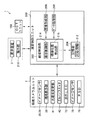
図2は、演算制御ユニット200の機能ブロック図である。図2に示すように、演算制御ユニット200は、統括制御部202、記憶部204、画像形成部206、及びデータ処理部208等を備える。なお、本実施形態において演算制御ユニット200内の「〜部」として説明するものは「〜回路」、「〜装置」、又は「〜機器」であってもよい。すなわち、「〜部」として説明するものは、ファームウェア、ソフトウェア、及びハードウェアまたはこれらの組み合わせのいずれで構成されても構わない。また、演算制御ユニット200には、既述の眼底カメラユニット2の各部、表示装置3、及びOCTユニット100の他に、操作部210が接続されている。操作部210は、操作レバー、キーボード、マウス、及びタッチパネル式のモニタ等の公知の操作デバイスであり、検者による各種の入力操作を受け付ける。
[Operation control unit]
FIG. 2 is a functional block diagram of the arithmetic and control unit 200. As shown in FIG. 2, the arithmetic and control unit 200 includes an overall control unit 202, a storage unit 204, an image forming unit 206, a data processing unit 208, and the like. In the present embodiment, what is described as “—unit” in the arithmetic and control unit 200 may be “—circuit”, “—device”, or “—device”. That is, what is described as the “unit” may be configured by firmware, software, hardware, or a combination thereof. An operation unit 210 is connected to the arithmetic and control unit 200 in addition to the components of the fundus camera unit 2, the display device 3, and the OCT unit 100. The operation unit 210 is a known operation device such as an operation lever, a keyboard, a mouse, and a touch panel type monitor, and receives various input operations by the examiner.

統括制御部202は、検者による操作部210への入力操作に応じて、眼底カメラユニット2、表示装置3、及びOCTユニット100の各部の動作を統括制御する。なお、図2では、統括制御部202の各種機能の中で固視標90の表示制御に係る機能のみを図示し、他の機能については公知技術であるので具体的な図示は省略する。   The general control unit 202 generally controls the operations of the respective units of the fundus camera unit 2, the display device 3, and the OCT unit 100 in accordance with an input operation performed by the examiner on the operation unit 210. In FIG. 2, only functions related to display control of the fixation target 90 among various functions of the general control unit 202 are illustrated, and other functions are well-known technologies, and thus specific illustration is omitted.

統括制御部202の機能は、各種のプロセッサ(Processor)を用いて実現できる。各種のプロセッサには、CPU(Central Processing Unit)、GPU(Graphics Processing Unit)、ASIC(Application Specific Integrated Circuit)、及びプログラマブル論理デバイス[例えばSPLD(Simple Programmable Logic Devices)、CPLD(Complex Programmable Logic Device)、及びFPGA(Field Programmable Gate Arrays)]等が含まれる。なお、統括制御部202の各種機能は、1つのプロセッサにより実現されてもよいし、同種または異種の複数のプロセッサで実現されてもよい。   The function of the central control unit 202 can be realized using various processors. Various processors include a CPU (Central Processing Unit), a GPU (Graphics Processing Unit), an ASIC (Application Specific Integrated Circuit), and a programmable logic device [for example, SPLD (Simple Programmable Logic Devices), CPLD (Complex Programmable Logic Device), And FPGA (Field Programmable Gate Arrays)]. The various functions of the general control unit 202 may be realized by one processor, or may be realized by a plurality of same or different processors.

記憶部204は、統括制御部202のプロセッサが実行する制御プログラムの他、OCT画像の画像データ、眼底像の画像データ、及び被検眼情報(被検者情報を含む)などを記憶する。また、記憶部204は、詳しくは後述する対応情報212を記憶している。   The storage unit 204 stores image data of an OCT image, image data of a fundus image, eye information (including subject information), and the like, in addition to a control program executed by the processor of the overall control unit 202. Further, the storage unit 204 stores correspondence information 212 described later in detail.

画像形成部206は、OCTユニット100から入力される検出信号を解析して眼底EfのOCT画像を形成する。なお、OCT画像の具体的な形成方法は、従来のOCT装置と同様である。データ処理部208は、画像形成部206により形成されたOCT画像、及び既述の眼底カメラユニット2により取得された画像(眼底像及び前眼部像)に対して画像処理等を施す。   The image forming unit 206 analyzes the detection signal input from the OCT unit 100 and forms an OCT image of the fundus oculi Ef. The specific method of forming an OCT image is the same as that of a conventional OCT apparatus. The data processing unit 208 performs image processing and the like on the OCT image formed by the image forming unit 206 and the images (fundus image and anterior eye image) acquired by the fundus camera unit 2 described above.

[固視標の提示(表示)制御]
統括制御部202は、被検眼Eに固視標90の提示を行う場合、記憶部204から読み出した制御プログラムを実行することにより表示制御部214として機能する。なお、表示制御部214は、本発明の位置制御部、軌跡表示制御部、及び視標表示制御部に相当する。
[Presentation (display) control of fixation target]
When presenting the fixation target 90 to the subject's eye E, the overall control unit 202 functions as the display control unit 214 by executing the control program read from the storage unit 204. The display control unit 214 corresponds to the position control unit, the trajectory display control unit, and the optotype display control unit of the present invention.

図3から図6は、表示制御部214が視標表示部39に表示させる固視標90、すなわち被検眼Eに提示される固視標90の一例を説明するための説明図である。ここでは、表示制御部214は本発明の視標表示制御部として機能する。   FIGS. 3 to 6 are explanatory diagrams illustrating an example of the fixation target 90 displayed on the target display unit 39 by the display control unit 214, that is, the fixation target 90 presented to the eye E to be examined. Here, the display control unit 214 functions as the optotype display control unit of the present invention.

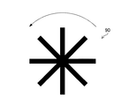
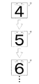
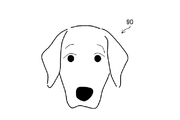
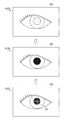
図3から図5に示すように、表示制御部214は、視標表示部39に固視標90を表示させる場合に固視標90の表示態様を時間的に変化させる。例えば、図3に示すように、表示制御部214は、固視標90の中心を基準として回転(自転)する固視標90を視標表示部39に表示させる。また、図4に示すように、表示制御部214は、拡大及び縮小を反復する固視標90を視標表示部39に表示させる。さらに、図5に示すように、表示制御部214は、自転する数字を含む固視標90であって且つ時間経過に応じて数字が入れ替わる表示態様の固視標90を視標表示部39に表示させる。このように視標表示部39に表示される固視標90の表示態様を時間変化させることで、被検者の注意を引くことができる。これにより、被検眼Eを固視標90に誘導し易くなる。   As shown in FIGS. 3 to 5, the display control unit 214 temporally changes the display mode of the fixation target 90 when the fixation target 90 is displayed on the target display unit 39. For example, as illustrated in FIG. 3, the display control unit 214 causes the optotype display unit 39 to display the fixation target 90 that rotates (rotates) with respect to the center of the optotype 90. Further, as shown in FIG. 4, the display control unit 214 causes the optotype display unit 39 to display a fixation target 90 that repeats enlargement and reduction. Further, as illustrated in FIG. 5, the display control unit 214 causes the optotype display unit 39 to display the fixation target 90 including the rotating numbers and the display mode in which the numbers are switched as time passes. Display. In this way, by changing the display mode of the fixation target 90 displayed on the target display unit 39 with time, the subject's attention can be drawn. This makes it easier to guide the eye E to the fixation target 90.

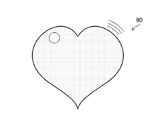
図6に示すように、表示制御部214は、予め定められた特定の画像(動物、乗り物、及びフィクションに登場するキャラクター等)を固視標90として視標表示部39に表示させてもよい。この場合にも、被検者の注意を引くことができるので被検眼Eを固視標90に誘導し易くなる。   As illustrated in FIG. 6, the display control unit 214 may cause the optotype display unit 39 to display a predetermined specific image (animal, vehicle, character appearing in fiction, and the like) as the fixation target 90. . Also in this case, since the subject's attention can be attracted, the eye E can be easily guided to the fixation target 90.

表示制御部214は、検者により操作部210に入力された眼底Efの検査(撮影)対象部位の指定操作に基づき、視標表示部39に表示させる固視標90の表示位置を制御する。そして、表示制御部214は、視標表示部39に表示される固視標90の表示位置を制御することで、固視標90の光束が対物レンズ22を通過する位置である視標位置を、対物レンズ22の光軸OA(図8参照)に対して垂直方向(XY方向:図1参照)に制御する。すなわち、表示制御部214に被検眼Eに提示する固視標90の提示位置を上述の垂直方向に制御する。以下、既述の指定操作に対応した表示位置で視標表示部39に表示された固視標90の光束が対物レンズ22を通過する位置を「目標位置」という。   The display control unit 214 controls the display position of the fixation target 90 to be displayed on the optotype display unit 39 based on an operation of designating a target part of the examination (imaging) of the fundus oculi Ef input by the examiner to the operation unit 210. Then, the display control unit 214 controls the display position of the fixation target 90 displayed on the target display unit 39, thereby changing the target position where the light flux of the fixation target 90 passes through the objective lens 22. The control is performed in a direction perpendicular to the optical axis OA of the objective lens 22 (see FIG. 8) (XY directions: see FIG. 1). That is, the presentation position of the fixation target 90 to be presented to the subject's eye E to the display control unit 214 is controlled in the above-described vertical direction. Hereinafter, the position where the light flux of the fixation target 90 displayed on the target display unit 39 at the display position corresponding to the above-described designation operation passes through the objective lens 22 is referred to as a “target position”.

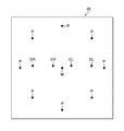
図7は、眼底Efの検査対象部位と視標表示部39の表示面内での固視標90の表示位置との関係の一例を示した説明図である。   FIG. 7 is an explanatory diagram showing an example of the relationship between the examination target site of the fundus oculi Ef and the display position of the fixation target 90 on the display surface of the target display unit 39.

図7に示すように、符号「M」は、被検眼Eの両眼の眼底Efの黄斑に対応した固視標90の表示位置である。なお、この表示位置Mは、対物レンズ22の光軸OA(図8参照)の位置に対応している。すなわち、表示位置Mで表示された固視標90の光束は、対物レンズ22の光軸OAを通る。   As shown in FIG. 7, the symbol “M” is the display position of the fixation target 90 corresponding to the macula of the fundus oculi Ef of both eyes of the subject's eye E. The display position M corresponds to the position of the optical axis OA (see FIG. 8) of the objective lens 22. That is, the light flux of the fixation target 90 displayed at the display position M passes through the optical axis OA of the objective lens 22.

符号「CR」は、被検眼Eの右眼の眼底Efの眼底中心に対応する固視標90の表示位置であり、符号「CL」は、被検眼Eの左眼の眼底Efの眼底中心に対応する固視標90の表示位置である。符号「DR」は、被検眼Eの右眼の眼底Efの視神経乳頭に対応する固視標90の表示位置であり、符号「DL」は、被検眼Eの左眼の眼底Efの視神経乳頭に対応する固視標90の表示位置である。符号「P」は、被検眼Eの両眼の眼底Efの眼底周辺部の8個の位置に対応する固視標90の表示位置である。   The symbol “CR” indicates the display position of the fixation target 90 corresponding to the center of the fundus Ef of the fundus oculi Ef of the right eye of the eye E to be examined, and the symbol “CL” indicates the center of the fundus Ef of the fundus Ef of the left eye of the eye E to be examined. The display position of the corresponding fixation target 90. The symbol “DR” is the display position of the fixation target 90 corresponding to the optic disc of the fundus oculi Ef of the right eye of the eye E to be examined, and the symbol “DL” is the optic disc of the fundus oculi Ef of the left eye of the eye E to be examined. The display position of the corresponding fixation target 90. Symbols “P” are display positions of the fixation target 90 corresponding to eight positions around the fundus oculi of the fundus oculi Ef of both eyes of the eye E to be examined.

なお、視標表示部39に表示される固視標90の表示位置は図7に示した位置に限定されるものではなく、適宜変更してもよい。また、他の検査対象部位(例えば黄斑と視神経乳頭との中間位置)に対応する表示位置を追加してもよい。   The display position of the fixation target 90 displayed on the target display unit 39 is not limited to the position shown in FIG. 7 and may be changed as appropriate. Further, a display position corresponding to another examination target site (for example, an intermediate position between the macula and the optic disc) may be added.

視標表示部39に表示された固視標90の光束は、既述の通り、ハーフミラー39Aからダイクロイックミラー46を経た後、対物レンズ22を通して被検眼Eに投射される。これにより、被検眼Eに固視標90を提示して、被検眼Eに固視標90を固視させることができる。   The luminous flux of the fixation target 90 displayed on the target display unit 39 is projected from the half mirror 39A through the dichroic mirror 46 to the eye E through the objective lens 22 as described above. Thus, the fixation target 90 can be presented to the subject's eye E and the fixation target 90 can be fixed to the subject's eye E.

図8は、被検者側から見た対物レンズ22の正面拡大図である。図8及び既述の図7に示すように、視標表示部39の表示位置Mで表示された固視標90の光束は、対物レンズ22の後述のレンズ中心部22a内の視標位置TM(光軸OAに相当)を通って被検眼Eに投射される。これにより、被検眼E(右眼及び左眼)が視標位置TM上の固視標90を固視することで、OCTユニット100から出射される信号光の照射位置(スキャン位置)に眼底Efの黄斑が移動される。   FIG. 8 is an enlarged front view of the objective lens 22 viewed from the subject. As shown in FIG. 8 and FIG. 7 described above, the luminous flux of the fixation target 90 displayed at the display position M of the target display unit 39 is converted into a target position TM in a later-described lens center portion 22a of the objective lens 22. (Corresponding to the optical axis OA) and projected onto the eye E to be examined. As a result, the eye E (right eye and left eye) fixes the fixation target 90 on the target position TM, so that the fundus Ef is located at the irradiation position (scan position) of the signal light emitted from the OCT unit 100. The macula is moved.

視標表示部39の表示位置CRで表示された固視標90の光束は、レンズ中心部22a内の視標位置TCRを通って被検眼Eに投射される。また、視標表示部39の表示位置CLで表示された固視標90の光束は、レンズ中心部22a内の視標位置TCLを通って被検眼Eに投射される。これにより、被検眼Eの右眼が視標位置TCR上の固視標90を固視したり、或いは左眼が視標位置TCL上の固視標90を固視したりすることで、眼底Efの眼底中心が既述の信号光の照射位置に移動される。   The luminous flux of the fixation target 90 displayed at the display position CR of the target display unit 39 is projected to the eye E through the target position TCR in the lens center 22a. The luminous flux of the fixation target 90 displayed at the display position CL of the target display unit 39 is projected onto the eye E through the target position TCL in the lens center 22a. Thereby, the right eye of the subject's eye E fixes the fixation target 90 at the target position TCR, or the left eye fixes the fixation target 90 at the target position TCL, thereby forming a fundus. The fundus center of Ef is moved to the above-mentioned signal light irradiation position.

視標表示部39の表示位置DRで表示された固視標90の光束は、対物レンズ22の後述のレンズ周辺部22b内の視標位置TDRを通って被検眼Eに投射される。また、視標表示部39の表示位置DLで表示された固視標90の光束は、レンズ周辺部22b内の視標位置TDLを通って被検眼Eに投射される。これにより、被検眼Eの右眼が視標位置TDR上の固視標90を固視したり、或いは左眼が視標位置TDL上の固視標90を固視したりすることで、眼底Efの視神経乳頭が既述の信号光の照射位置に移動される。   The luminous flux of the fixation target 90 displayed at the display position DR of the target display unit 39 is projected onto the eye E through a target position TDR in a later-described lens peripheral portion 22b of the objective lens 22. The luminous flux of the fixation target 90 displayed at the display position DL of the target display unit 39 is projected to the eye E through the target position TDL in the lens peripheral part 22b. Thereby, the right eye of the subject's eye E fixes the fixation target 90 on the target position TDR, or the left eye fixes the fixation target 90 on the target position TDL, thereby forming a fundus. The optic disc of Ef is moved to the above-described signal light irradiation position.

視標表示部39の各表示位置Pでそれぞれ表示された固視標90の光束は、レンズ周辺部22b内の各視標位置TPをそれぞれ通って被検眼Eに投射される。これにより、被検眼E(右眼及び左眼)が各視標位置TPのいずれかの視標位置TP上の固視標90を固視することで、眼底Efの8か所の眼底周辺部のいずれかが既述の信号光の照射位置に移動される。   The luminous flux of the fixation target 90 displayed at each display position P of the target display unit 39 is projected to the eye E through each target position TP in the lens peripheral portion 22b. As a result, the subject's eye E (the right eye and the left eye) fixes the fixation target 90 on any one of the target positions TP of the respective target positions TP, and thereby the eight peripheral portions of the fundus oculi Ef around the fundus Is moved to the above-described signal light irradiation position.

レンズ中心部22aは、対物レンズ22の光軸OAを中心とする一定範囲内の領域であり、本実施形態では既述の視標位置TM及び視標位置TCR,TCLを含む。ここで、対物レンズ22の視標位置TM及び視標位置TCR,TCLをそれぞれ通過した固視標90を被検眼Eが固視する場合に、固視標90は被検者の視野範囲の中央領域に位置するため、被検眼Eを大きく回旋させる必要はない。このため、被検眼Eを容易に固視標90に誘導することができる。従って、レンズ中心部22aは、対物レンズ22の中で被検眼Eを固視標90に容易に誘導することが可能な領域である。   The lens center portion 22a is a region within a certain range centered on the optical axis OA of the objective lens 22, and includes the target position TM and the target positions TCR and TCL described above in the present embodiment. Here, when the subject's eye E fixes the fixation target 90 that has passed through the target position TM and the target positions TCR and TCL of the objective lens 22, the fixation target 90 is positioned at the center of the visual field range of the subject. Since the eye E is located in the region, it is not necessary to rotate the eye E to a large extent. Therefore, the subject's eye E can be easily guided to the fixation target 90. Therefore, the lens center portion 22 a is an area in the objective lens 22 where the eye E can be easily guided to the fixation target 90.

なお、レンズ中心部22aは、対物レンズ22の中で図4に示す範囲に限定されるものではなく、視標位置TMのみを含む範囲であったり、或いは視標位置TDR,TDLまでを含む範囲であったり、眼底Efの他の検査対象部位(黄斑と視神経乳頭との中間位置等)に対応する視標位置を含む範囲であったりしてもよい。   The lens center portion 22a is not limited to the range shown in FIG. 4 in the objective lens 22, but is a range including only the target position TM or a range including the target positions TDR and TDL. Alternatively, the range may include a target position corresponding to another examination target site (eg, an intermediate position between the macula and the optic disc) of the fundus oculi Ef.

レンズ周辺部22bは、対物レンズ22の中で既述のレンズ中心部22aの外側の領域であり、本実施形態では既述の視標位置TDR,TDL及び視標位置TPを含む。ここで、対物レンズ22の視標位置TDR,TDL及び視標位置TPをそれぞれ通過した固視標90を被検眼Eが固視する場合に、固視標90は被検者の視野範囲の中央領域に存在しないので、被検眼Eを大きく回旋させる必要がある。このため、被検眼Eが固視標90を見失うおそれがあり、被検眼Eを固視標90に誘導することが困難である。   The lens peripheral portion 22b is a region outside the above-described lens center portion 22a in the objective lens 22, and includes the above-described target positions TDR, TDL and the target position TP in the present embodiment. Here, when the subject's eye E fixes the fixation target 90 that has passed through the target positions TDR, TDL and the target position TP of the objective lens 22, the fixation target 90 is positioned at the center of the visual field range of the subject. Since the eye E does not exist in the region, it is necessary to largely rotate the eye E to be examined. For this reason, the eye E may lose sight of the fixation target 90, and it is difficult to guide the eye E to the fixation target 90.

従って、表示制御部214は、検査対象部位に対応する目標位置(各視標位置TP,TCR,…TP)がレンズ中心部22a内及びレンズ周辺部22b内のいずれであるかに応じて、視標表示部39による固視標90の表示制御方法を切り替える。これにより、目標位置がレンズ中心部22a内及びレンズ周辺部22b内のいずれであるかに応じて、固視標90の視標位置の位置制御方法が異なる。   Therefore, the display control unit 214 determines whether the target position (the target positions TP, TCR,... TP) corresponding to the inspection target part is within the lens center part 22a or the lens peripheral part 22b. The display control method of the fixation target 90 by the target display unit 39 is switched. Thus, the position control method of the target position of the fixation target 90 differs depending on whether the target position is inside the lens center part 22a or inside the lens peripheral part 22b.

この際に、既述の図3に示した記憶部204には、複数の検査対象部位と、検査対象部位ごとの視標表示部39による固視標90の表示制御方法と、の対応関係を示す対応情報212が記憶されている。固視標90の表示制御方法には、レンズ中心部22a内の目標位置(視標位置TM,TCR,TCL)に対応した限定制御と、レンズ周辺部22b内の目標位置(視標位置TDR,TDL,TP)に対応した移動制御と、が含まれる。   At this time, the storage unit 204 shown in FIG. 3 described above stores the correspondence between the plurality of test target sites and the display control method of the fixation target 90 by the target display unit 39 for each test target site. The stored correspondence information 212 is stored. The display control method of the fixation target 90 includes limited control corresponding to a target position (target position TM, TCR, TCL) in the lens center portion 22a, and a target position (target position TDR, target position) in the lens peripheral portion 22b. TDL, TP).

そして、表示制御部214は、操作部210に対する指定操作で指定された検査対象部位に基づき、記憶部204内の対応情報212を参照することで、目標位置がレンズ中心部22a内である場合には視標表示部39に限定制御を実行させ、目標位置がレンズ周辺部22b内である場合には視標表示部39に移動制御を実行させる。   Then, the display control unit 214 refers to the correspondence information 212 in the storage unit 204 based on the inspection target site specified by the specifying operation on the operation unit 210, and thus, when the target position is within the lens center 22a. Causes the optotype display unit 39 to execute the limited control, and causes the optotype display unit 39 to execute the movement control when the target position is within the lens peripheral portion 22b.

図9は、表示制御部214による限定制御を説明するための説明図である。なお、図9に示す例では、検査対象部位として被検眼E(右眼)の眼底Efの眼底中心が指定されたものとする。   FIG. 9 is an explanatory diagram for describing the limited control by the display control unit 214. In the example illustrated in FIG. 9, it is assumed that the fundus center of the fundus oculi Ef of the eye E (right eye) to be inspected is specified.

図9に示すように、表示制御部214は、目標位置が視標位置TCRである場合、対応情報212に基づき、レンズ中心部22a内の視標位置TCRに対応した限定制御を視標表示部39に実行させる。この場合、表示制御部214は、固視標90の視標位置が目標位置(ここでは視標位置TCR)に限定されるように、視標表示部39を制御する。具体的に表示制御部214は、視標表示部39内での固視標90の表示位置を表示位置CRに限定する。これにより、後述の移動制御とは異なり、固視標90を被検眼Eに速やかに提示することができる。   As illustrated in FIG. 9, when the target position is the target position TCR, the display control unit 214 performs the limited control corresponding to the target position TCR in the lens center 22a based on the correspondence information 212. 39. In this case, the display control unit 214 controls the optotype display unit 39 such that the optotype position of the fixation target 90 is limited to the target position (here, the optotype position TCR). Specifically, the display control unit 214 limits the display position of the fixation target 90 in the target display unit 39 to the display position CR. Thus, unlike the movement control described later, the fixation target 90 can be promptly presented to the subject's eye E.

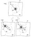
図10は、表示制御部214による移動制御を説明するための説明図である。なお、図10に示す例では、検査対象部位として被検眼E(右眼及び左眼のいずれでも可)の眼底Efの眼底周辺部の1箇所が指定されたものとする。この場合に、表示制御部214は本発明の位置制御部として機能する。   FIG. 10 is an explanatory diagram for explaining movement control by the display control unit 214. In the example illustrated in FIG. 10, it is assumed that one portion of the fundus oculi peripheral portion of the fundus oculi Ef of the eye E (either the right eye or the left eye) is specified as the inspection target site. In this case, the display control unit 214 functions as the position control unit of the present invention.

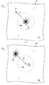
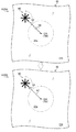
図10の符号XAに示すように、表示制御部214は、目標位置が視標位置TPである場合、対応情報212に基づき、レンズ周辺部22b内の視標位置TPに対応した移動制御を視標表示部39に実行させる。最初に表示制御部214は、固視標90の視標位置がレンズ中心部22a内の所定の基準位置に一致(略一致を含む)するように、視標表示部39に固視標90を表示させる。ここで本実施形態の基準位置は光軸OAの位置であり、表示制御部214は、視標表示部39の表示位置Mに固視標90を表示させる。これにより、固視標90が被検者の視野範囲の中央領域に位置するので、被検眼Eが固視標90を容易に固視することができる。   As indicated by reference numeral XA in FIG. 10, when the target position is the target position TP, the display control unit 214 checks the movement control corresponding to the target position TP in the lens peripheral part 22b based on the correspondence information 212. The mark display section 39 is caused to execute the processing. First, the display control unit 214 displays the fixation target 90 on the target display unit 39 such that the position of the target of the fixation target 90 matches a predetermined reference position in the lens center portion 22a (including substantially matching). Display. Here, the reference position in the present embodiment is the position of the optical axis OA, and the display control unit 214 displays the fixation target 90 at the display position M of the target display unit 39. Thereby, the fixation target 90 is located in the central region of the visual field range of the subject, so that the subject's eye E can easily fixate on the fixation target 90.

次いで、表示制御部214は、図中の矢印αで示すように、固視標90の視標位置が基準位置から指定操作で指定された目標位置(ここでは視標位置TP)に向けて移動するように、視標表示部39の表示制御を行う。なお、矢印αは固視標90の移動方向を示したものであり、この矢印αが視標表示部39に実際に表示されていないくともよいし或いは表示されていてもよい。   Next, the display control unit 214 moves the optotype position of the fixation target 90 from the reference position to the target position (here, the optotype position TP) specified by the specifying operation, as indicated by the arrow α in the drawing. The display control of the optotype display unit 39 is performed so that The arrow α indicates the direction in which the fixation target 90 moves, and the arrow α may or may not actually be displayed on the target display unit 39.

具体的に表示制御部214は、視標表示部39内での固視標90の表示位置を表示位置Mから表示位置Pに向けて移動させる。この際に固視標90の移動速度は、被検眼Eが固視標90を見失わない速度に設定されている。これにより、図10の符号XBに示すように、固視標90の視標位置が基準位置(光軸OA)から目標位置(視標位置TP)に向けてゆっくり移動するため、被検眼Eの固視位置を基準位置から目標位置に向けて誘導することができる。   Specifically, the display control unit 214 moves the display position of the fixation target 90 in the target display unit 39 from the display position M to the display position P. At this time, the moving speed of the fixation target 90 is set to a speed at which the eye E does not lose sight of the fixation target 90. Thereby, as shown by the symbol XB in FIG. 10, the optotype position of the fixation target 90 slowly moves from the reference position (optical axis OA) to the target position (optotype position TP). The fixation position can be guided from the reference position to the target position.

また、表示制御部214は、視標表示部39に既述の移動制御を実行させる場合に、基準位置に対応する表示位置Mから目標位置に対応する表示位置Pに向けて移動する固視標90の軌跡像92を視標表示部39に表示させる。この場合、表示制御部214は本発明の軌跡表示制御部として機能する。   In addition, when causing the optotype display unit 39 to perform the above-described movement control, the display control unit 214 moves from the display position M corresponding to the reference position to the display position P corresponding to the target position. A track image 92 of 90 is displayed on the optotype display unit 39. In this case, the display control unit 214 functions as a locus display control unit of the present invention.

視標表示部39に表示された軌跡像92の光束は、固視標90の光束と共にハーフミラー39Aから対物レンズ22を通して被検眼Eに投射される。その結果、対物レンズ22上において基準位置から目標位置(視標位置TP)に向けて移動する固視標90の視標位置の軌跡を示す軌跡像92が被検眼Eに提示される。これにより、被検眼Eの固視位置を基準位置から視標位置TPまで確実に誘導することができる。   The luminous flux of the trajectory image 92 displayed on the optotype display unit 39 is projected onto the eye E through the objective lens 22 from the half mirror 39A together with the luminous flux of the fixation target 90. As a result, a trajectory image 92 indicating the trajectory of the target position of the fixation target 90 moving from the reference position to the target position (target position TP) on the objective lens 22 is presented to the eye E. Thus, the fixation position of the eye E can be reliably guided from the reference position to the target position TP.

このように表示制御部214は、操作部210に対する指定操作で指定された目標位置がレンズ中心部22a内である場合には視標表示部39に限定制御を実行させ、この目標位置がレンズ周辺部22b内である場合には視標表示部39に移動制御を実行させる。   As described above, when the target position specified by the specifying operation on the operation unit 210 is within the lens center 22a, the display control unit 214 causes the optotype display unit 39 to execute the limited control, and the target position is When it is within the section 22b, the optotype display section 39 executes the movement control.

なお、被検眼EのOCT検査では被検眼Eに対して複数の目標位置を順番に提示する場合がある。この場合、表示制御部214は、操作部210に対する指定操作で指定された複数の目標位置ごとに、目標位置がレンズ中心部22a内或いはレンズ周辺部22b内であるかに応じて、限定制御又は移動制御を視標表示部39に順番に実行させる。   In the OCT examination of the eye E, a plurality of target positions may be sequentially presented to the eye E. In this case, for each of the plurality of target positions specified by the specifying operation on the operation unit 210, the display control unit 214 performs the limitation control or the limited control according to whether the target position is within the lens center part 22a or the lens peripheral part 22b. The movement control is performed by the optotype display unit 39 in order.

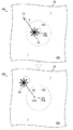
図11は、表示制御部214による移動制御を行う場合の基準位置の変形例を説明するための説明図である。ここでは、目標位置をレンズ中心部22a内の位置(視標位置TCR:符号XIA参照)からレンズ周辺部22b内の位置(視標位置TP:符号XIB参照)に切り替える場合を例に挙げて説明を行う。   FIG. 11 is an explanatory diagram for describing a modification of the reference position when the movement control is performed by the display control unit 214. Here, an example will be described in which the target position is switched from a position in the lens center portion 22a (a target position TCR: reference sign XIA) to a position in the lens peripheral portion 22b (a target position TP: reference sign XIB). I do.

図11に示すように、表示制御部214は、1つ前の目標位置、すなわちレンズ中心部22a内の視標位置TCRを基準位置として、この基準位置から固視標90の視標位置を新目標位置に向けて移動させる移動制御を視標表示部39に実行させる。   As shown in FIG. 11, the display control unit 214 sets the target position immediately before, that is, the target position TCR in the lens center 22a as a reference position, and changes the target position of the fixation target 90 from this reference position. The optotype display unit 39 executes the movement control for moving the target to the target position.

このように目標位置をレンズ中心部22a内の位置からレンズ周辺部22b内の位置に切り替える場合に、先のレンズ中心部22a内の目標位置を基準位置とすることで、固視標90の視標位置を光軸OAに合せる必要がなくなる。このため、被検眼Eの固視位置を視標位置TPまで誘導させる際の誘導時間を短くすることができる。   When the target position is switched from the position in the lens central portion 22a to the position in the lens peripheral portion 22b as described above, the target position in the lens central portion 22a is set as the reference position, so that the fixation target 90 is viewed. There is no need to align the target position with the optical axis OA. For this reason, the guidance time for guiding the fixation position of the eye E to the target position TP can be reduced.

[眼科装置の作用]
図12は、上記構成の眼科装置1による被検眼Eの検査処理、特に被検眼Eに対する固視標90の提示処理の流れ(本発明の眼科装置の作動方法に相当)を示すフローチャートである。
[Operation of ophthalmic device]
FIG. 12 is a flowchart showing a flow of inspection processing of the eye E to be inspected by the ophthalmologic apparatus 1 having the above configuration, in particular, processing of presenting the fixation target 90 to the eye E (corresponding to an operation method of the ophthalmologic apparatus of the present invention).

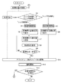
図12に示すように、眼科装置1での所定の検査準備処理が完了した後、検者が操作部210に対して眼底Efの検査対象部位の指定操作を行う(ステップS1)。そして、統括制御部202の表示制御部214は、指定操作で指定された検査対象部位に基づき、記憶部204内の対応情報212を参照して、視標表示部39による固視標90の表示制御方法を決定する(ステップS2)。   As shown in FIG. 12, after the predetermined examination preparation processing in the ophthalmologic apparatus 1 is completed, the examiner performs an operation of designating the examination target site of the fundus oculi Ef on the operation unit 210 (step S1). Then, the display control unit 214 of the overall control unit 202 refers to the correspondence information 212 in the storage unit 204 based on the inspection target part specified by the specifying operation, and displays the fixation target 90 by the target display unit 39. The control method is determined (Step S2).

表示制御部214は、対応情報212に基づき、目標位置がレンズ中心部22a内の視標位置TM,TCR,TCL等である場合、既述の図9で説明したように視標表示部39に限定制御を開始させる(ステップS3)。この場合、視標表示部39は、固視標90の表示位置を目標位置に対応する位置(表示位置M,CR,CL等)に限定する。これにより、視標表示部39で表示された固視標90の光束が、ハーフミラー39Aから対物レンズ22を経て被検眼Eに投射される。その結果、被検眼Eに固視標90が提示される(ステップS4)。   Based on the correspondence information 212, when the target position is the target position TM, TCR, TCL, or the like in the lens center 22a, the display control unit 214 transmits the target position to the target display unit 39 as described with reference to FIG. The limited control is started (step S3). In this case, the optotype display unit 39 limits the display position of the fixation target 90 to a position (display position M, CR, CL, or the like) corresponding to the target position. Thereby, the light flux of the fixation target 90 displayed on the target display unit 39 is projected from the half mirror 39A to the eye E via the objective lens 22. As a result, the fixation target 90 is presented to the eye E (step S4).

目標位置がレンズ中心部22a内である場合、固視標90が被検者の視野範囲の中央領域に位置するので、被検眼Eが固視標90を容易に固視することができる。また、この場合には、移動制御のような固視標90の移動は行わないので、被検眼Eの固視位置を速やかに目標位置に誘導することができる。   When the target position is within the lens center 22a, the fixation target 90 is located in the central region of the visual field range of the subject, so that the subject's eye E can easily fixate on the fixation target 90. In this case, since the fixation target 90 is not moved as in the movement control, the fixation position of the eye E can be quickly guided to the target position.

一方、表示制御部214は、対応情報212に基づき、目標位置がレンズ周辺部22b内の視標位置TDR,TDL,TP等である場合、既述の図10で説明したように視標表示部39に移動制御を開始させる(ステップS5)。最初に表示制御部214は、視標表示部39の表示位置Mに固視標90を表示させる。これにより、視標表示部39に表示された固視標90の光束がハーフミラー39Aから対物レンズ22を経て被検眼Eに投射され、対物レンズ22の光軸OAに対応する基準位置にて固視標90が被検眼Eに提示される(ステップS6)。その結果、被検眼Eが固視標90を容易に固視することができる。   On the other hand, when the target position is the target position TDR, TDL, TP, or the like in the lens peripheral portion 22b based on the correspondence information 212, the display control unit 214, as described with reference to FIG. The movement control is started by 39 (step S5). First, the display control unit 214 causes the fixation target 90 to be displayed at the display position M of the target display unit 39. Accordingly, the light flux of the fixation target 90 displayed on the target display unit 39 is projected from the half mirror 39A through the objective lens 22 to the subject's eye E, and fixed at a reference position corresponding to the optical axis OA of the objective lens 22. The optotype 90 is presented to the eye E (step S6). As a result, the subject's eye E can easily fixate on the fixation target 90.

次いで、表示制御部214は、視標表示部39内での固視標90の表示位置を表示位置Mから目標位置に対応する表示位置(表示位置DR,DL,P)に向けて所定速度で移動させる。これにより、固視標90の視標位置が基準位置から目標位置に向けてゆっくり移動する(ステップS7)。これにより、被検眼Eの固視位置を基準位置から目標位置に向けて誘導することができる。   Next, the display control unit 214 moves the display position of the fixation target 90 in the target display unit 39 from the display position M to a display position (display position DR, DL, P) corresponding to the target position at a predetermined speed. Move. Thereby, the target position of the fixation target 90 slowly moves from the reference position to the target position (step S7). Thereby, the fixation position of the eye E can be guided from the reference position to the target position.

また、同時に表示制御部214は、視標表示部39を制御して、表示位置Mから目標位置に対応する表示位置に向けて移動する固視標90の軌跡像92を表示させる(ステップS8)。これにより、軌跡像92の光束がハーフミラー39Aから対物レンズ22を経て被検眼Eに投射される。その結果、目標位置に向けて移動する固視標90の視標位置の軌跡像92が被検眼Eに提示されるので、被検眼Eの固視位置を目標位置に向けて確実に誘導することができる。   At the same time, the display control unit 214 controls the target display unit 39 to display the trajectory image 92 of the fixation target 90 moving from the display position M to the display position corresponding to the target position (step S8). . Thereby, the light beam of the trajectory image 92 is projected from the half mirror 39A to the eye E through the objective lens 22. As a result, since the trajectory image 92 of the target position of the fixation target 90 moving toward the target position is presented to the eye E, it is possible to reliably guide the fixation position of the eye E toward the target position. Can be.

以下、固視標90の視標位置が目標位置に到達するまで、既述のステップS7,S8の処理が繰り返し実行される(ステップS9)。これにより、被検眼Eの固視位置が目標位置に誘導される。   Hereinafter, until the target position of the fixation target 90 reaches the target position, the processing of the above-described steps S7 and S8 is repeatedly executed (step S9). Thereby, the fixation position of the eye E is guided to the target position.

また、既述のステップS2からステップS9までの処理と並行して或いは前後して、統括制御部202は、照明光学系10の照明光の光量の設定と、撮影光学系30の観察照明光の光量の設定を行う(ステップS10)。なお、各光量の設定方法については公知技術であるので、ここでは具体的な説明は省略する。   Further, in parallel with or before or after the processing from step S2 to step S9 described above, the general control unit 202 sets the amount of illumination light of the illumination optical system 10 and sets the amount of observation illumination light of the imaging optical system 30. The light amount is set (step S10). In addition, since the setting method of each light quantity is a well-known technique, a specific description is omitted here.

次いで、前眼部Eaに対する眼底カメラユニット2のアライメントと、眼底Efに対する眼底カメラユニット2のフォーカス調整とが、統括制御部202の制御の下において自動で実行、或いは操作部210に対する操作入力により手動で実行される(ステップS11)。そして、眼底カメラユニット2及びOCTユニット100等による眼底Efの撮影画像及びOCT画像の撮影が実行される(ステップS12)。なお、ステップS11,S12の各処理についても公知技術であるので、ここでは具体的な説明は省略する。   Next, the alignment of the fundus camera unit 2 with respect to the anterior ocular segment Ea and the focus adjustment of the fundus camera unit 2 with respect to the fundus oculi Ef are automatically executed under the control of the general control unit 202, or are manually performed by an operation input to the operation unit 210. (Step S11). Then, a photographed image of the fundus oculi Ef and an OCT image are photographed by the fundus camera unit 2 and the OCT unit 100 (step S12). In addition, since each process of steps S11 and S12 is a known technique, a specific description is omitted here.

以下、検査対象部位を変更する場合には、上述のステップS1からステップS12までの処理が繰り返し実行される(ステップS13)。なお、既述の図11で説明したように、1つ前の目標位置がレンズ中心部22a内の視標位置TM,TCR,TCLである場合、表示制御部214は、既述の図12に示したステップS6において、先の目標位置を基準位置として、視標表示部39に固視標90を表示させる。これにより、被検眼Eの固視位置を目標位置まで誘導させる際の誘導時間を短くすることができる。   Hereinafter, when changing the inspection target site, the above-described processes from step S1 to step S12 are repeatedly executed (step S13). Note that, as described in FIG. 11 described above, when the immediately preceding target position is the target positions TM, TCR, and TCL in the lens center 22a, the display control unit 214 returns to FIG. In the illustrated step S6, the fixation target 90 is displayed on the target display unit 39 with the previous target position as a reference position. Thereby, the guidance time for guiding the fixation position of the eye E to the target position can be shortened.

[本実施形態の効果]
以上のように本実施形態では、検査対象部位に対応する目標位置がレンズ中心部22a内である場合には視標表示部39に限定制御を実行させ、且つ目標位置がレンズ周辺部22b内である場合には視標表示部39に移動制御を実行させることができる。これにより、目標位置がレンズ中心部22a内である場合には被検眼Eの固視位置を目標位置に速やかに誘導し、逆に目標位置がレンズ周辺部22b内である場合には被検眼Eの固視位置を基準位置から目標位置に向けて確実に誘導することができる。その結果、固視標90の光束が対物レンズ22を通過する位置に対応した最適な方法で被検眼Eに対して固視標90を提示することができる。
[Effects of the present embodiment]
As described above, in the present embodiment, when the target position corresponding to the inspection target site is within the lens center portion 22a, the optotype display unit 39 performs the limited control, and the target position is set within the lens peripheral portion 22b. In some cases, the optotype display unit 39 can execute the movement control. Accordingly, when the target position is within the lens center portion 22a, the fixation position of the eye E is quickly guided to the target position, and when the target position is within the lens peripheral portion 22b, the eye E is quickly detected. Can be reliably guided from the reference position to the target position. As a result, the fixation target 90 can be presented to the eye E by an optimal method corresponding to the position at which the light flux of the fixation target 90 passes through the objective lens 22.

[第2実施形態の眼科装置]
図13は、第2実施形態の眼科装置1の構成の一例を示す概略図である。この第2実施形態の眼科装置1は、既述の移動制御時において被検眼Eが注視している対物レンズ22上の視線位置を検出し、この視線位置の検出結果を既述の移動制御に反映する。
[Ophthalmic apparatus according to second embodiment]
FIG. 13 is a schematic diagram illustrating an example of a configuration of the ophthalmologic apparatus 1 according to the second embodiment. The ophthalmologic apparatus 1 according to the second embodiment detects a line-of-sight position on the objective lens 22 that the eye E is gazing at during the movement control described above, and converts the detection result of the line-of-sight position to the movement control described above. reflect.

図13に示すように、第2実施形態の眼科装置1は、眼底カメラユニット2がさらに視線位置検出光学系70を備える点を除けば上記第1実施形態の眼科装置1と基本的に同じ構成である。このため、上記第1実施形態と機能又は構成上同一のものについては、同一符号を付してその説明は省略する。   As shown in FIG. 13, the configuration of the ophthalmologic apparatus 1 of the second embodiment is basically the same as that of the ophthalmologic apparatus 1 of the above-described first embodiment except that the fundus camera unit 2 further includes a line-of-sight position detecting optical system 70. It is. Therefore, the same components as those in the first embodiment in function or configuration are denoted by the same reference numerals, and description thereof is omitted.

視線位置検出光学系70は、ミラー71と、赤外LED72と、ピンホール73と、集光レンズ74と、ミラー75と、結像レンズ76と、ミラー77と、イメージセンサ78と、半導体位置検出素子(Position Sensitive Detector)であるPSD79と、を備える。   The line-of-sight position detection optical system 70 includes a mirror 71, an infrared LED 72, a pinhole 73, a condenser lens 74, a mirror 75, an imaging lens 76, a mirror 77, an image sensor 78, and semiconductor position detection. A PSD 79 which is an element (Position Sensitive Detector).

ミラー71は、既述のダイクロイックミラー46と対物レンズ22との間に配置されており、例えばダイクロイックミラーが用いられる。このミラー71は、既述の照明光、観察照明光、及び信号光等(その反射光を含む)を透過させる。また、ミラー71は、後述のミラー75から入射した近赤外光を対物レンズ22に向けて反射すると共に、対物レンズ22から入射した近赤外光の反射光をミラー75に向けて反射する。   The mirror 71 is disposed between the dichroic mirror 46 and the objective lens 22 described above, and for example, a dichroic mirror is used. The mirror 71 transmits the above-described illumination light, observation illumination light, signal light, and the like (including the reflected light). The mirror 71 reflects near-infrared light incident from a mirror 75 described later toward the objective lens 22, and reflects reflected light of near-infrared light incident from the objective lens 22 toward the mirror 75.

赤外LED72は、近赤外光をピンホール73に向けて出射する。ピンホール73は、赤外LED72から入射した近赤外光を点光源とした後、この点光源の近赤外光を集光レンズ74に向けて出射する。集光レンズ74は、ピンホール73から入射した近赤外光をミラー75に向けて出射する。   The infrared LED 72 emits near-infrared light toward the pinhole 73. The pinhole 73 uses the near-infrared light incident from the infrared LED 72 as a point light source, and emits the near-infrared light of the point light source toward the condenser lens 74. The condenser lens 74 emits near-infrared light incident from the pinhole 73 toward the mirror 75.

ミラー75は、例えばハーフミラーが用いられる。このミラー75は、集光レンズ74から入射した近赤外光の一部をミラー71に向けてそのまま透過させる。これにより、ミラー75を透過した近赤外光は、ミラー71により対物レンズ22に向けて反射され、この対物レンズ22を通して被検眼Eに入射する。そして、被検眼Eにて反射された近赤外光の反射光が、対物レンズ22を通してミラー71に入射し、このミラー71によりミラー75に向けて反射される。ミラー75は、ミラー71から入射した反射光の一部を結像レンズ76に向けて反射する。   As the mirror 75, for example, a half mirror is used. The mirror 75 transmits part of the near-infrared light incident from the condenser lens 74 toward the mirror 71 as it is. Thus, the near-infrared light transmitted through the mirror 75 is reflected by the mirror 71 toward the objective lens 22 and enters the eye E through the objective lens 22. Then, the reflected light of the near-infrared light reflected by the eye E enters the mirror 71 through the objective lens 22, and is reflected toward the mirror 75 by the mirror 71. The mirror 75 reflects a part of the reflected light incident from the mirror 71 toward the imaging lens 76.

結像レンズ76は、ミラー75から入射した反射光をミラー77に向けて出射する。ミラー77は、結像レンズ76から入射した反射光の一部をイメージセンサ78に向けて反射すると共に、結像レンズ76から入射した反射光の残りをそのまま透過させてPSD79に向けて出射する。   The imaging lens 76 emits the reflected light from the mirror 75 toward the mirror 77. The mirror 77 reflects a part of the reflected light incident from the imaging lens 76 toward the image sensor 78, and transmits the rest of the reflected light incident from the imaging lens 76 as it is and emits it toward the PSD 79.

イメージセンサ78は、CMOS型又はCCD型であり、その撮像面にはミラー77によって反射された反射光が被検眼Eの像として結像する。イメージセンサ78は、撮像面に結像された被検眼Eの像を撮像して、その撮像画像データ150(図15参照)を統括制御部202(図14参照)へ出力する。   The image sensor 78 is a CMOS type or a CCD type, and the light reflected by the mirror 77 forms an image of the eye E on the imaging surface thereof. The image sensor 78 captures an image of the eye E formed on the imaging surface, and outputs the captured image data 150 (see FIG. 15) to the overall control unit 202 (see FIG. 14).

PSD79の受光面には、ミラー77から入射した反射光が入射する。PSD79は、その受光面における反射光の受光位置を検出可能なセンサであり、受光位置を示す受光信号を統括制御部202(図14参照)へ出力する。なお、PSD79の代わりにラインセンサを用いてもよい。   The reflected light from the mirror 77 is incident on the light receiving surface of the PSD 79. The PSD 79 is a sensor capable of detecting the light receiving position of the reflected light on the light receiving surface, and outputs a light receiving signal indicating the light receiving position to the overall control unit 202 (see FIG. 14). Note that a line sensor may be used instead of the PSD 79.

図14は、第2実施形態の演算制御ユニット200の機能ブロック図である。図14に示すように、第2実施形態の演算制御ユニット200は、統括制御部202が表示制御部214の他に視線位置検出部216として機能する点を除けば、第1実施形態の演算制御ユニット200の同じ構成である。   FIG. 14 is a functional block diagram of the arithmetic and control unit 200 according to the second embodiment. As shown in FIG. 14, the arithmetic and control unit 200 according to the second embodiment is different from the arithmetic and control unit according to the first embodiment except that the general control unit 202 functions as the line-of-sight position detection unit 216 in addition to the display control unit 214. This is the same configuration of the unit 200.

視線位置検出部216は、既述の視線位置検出光学系70と共に本発明の視線位置検出部を構成する。視線位置検出部216は、既述の図12に示した移動制御開始(ステップS5)に合わせて赤外LED72を点灯させると共に、イメージセンサ78から入力される被検眼Eの撮像画像データ150(図15参照)及びPSD79から入力される受光信号に基づき、対物レンズ22上で被検眼Eが注視している視線位置を検出する。   The line-of-sight position detection unit 216 forms a line-of-sight position detection unit of the present invention together with the line-of-sight position detection optical system 70 described above. The line-of-sight position detection unit 216 turns on the infrared LED 72 in accordance with the movement control start (step S5) shown in FIG. 12 described above, and captures image data 150 (see FIG. 15) and the light receiving signal input from the PSD 79, the gaze position at which the eye E is gazing on the objective lens 22 is detected.

図15は、プルキンエ像151を利用する視線位置検出部216の視線位置検出方法(角膜検出方式)を説明するための説明図である。図15の符号XVAに示すように、被検眼Eの角膜表面上には、点光源の近赤外光の入射により、近赤外光の反射像であるプルキンエ像151が生じる。このプルキンエ像151の位置は、被検眼Eの視線方向の変化に応じて変化する。   FIG. 15 is an explanatory diagram for describing a gaze position detection method (corneal detection method) of the gaze position detection unit 216 using the Purkinje image 151. As indicated by reference numeral XVA in FIG. 15, the incidence of near-infrared light from a point light source generates a Purkinje image 151, which is a reflection image of near-infrared light, on the corneal surface of the eye E. The position of the Purkinje image 151 changes according to a change in the line of sight of the eye E to be inspected.

従って、図15の符号XVBに示すように、視線位置検出部216は、イメージセンサ78から入力される被検眼Eの撮像画像データ150と、PSD79から入力される受光信号とに基づき、被検眼Eにおけるプルキンエ像151の位置座標C1を検出する。そして、視線位置検出部216は、位置座標C1が示すプルキンエ像151の位置と瞳孔中心との相対位置に基づいて、被検眼Eの視線方向を検出する。なお、プルキンエ像151を利用した視線方向の検出方法は公知技術であり、その詳細な説明は省略する。また、本実施形態ではPSD79を用いているが、PSD79を省略して、イメージセンサ78から入力される撮像画像データ150のみに基づいてプルキンエ像151の位置座標C1を検出してもよい。   Therefore, as indicated by reference numeral XVB in FIG. 15, the gaze position detection unit 216 determines the eye E based on the captured image data 150 of the eye E input from the image sensor 78 and the light receiving signal input from the PSD 79. Of the Purkinje image 151 are detected. Then, the line-of-sight position detection unit 216 detects the line-of-sight direction of the eye E based on the relative position between the position of the Purkinje image 151 indicated by the position coordinates C1 and the center of the pupil. The method of detecting the line of sight direction using the Purkinje image 151 is a known technique, and a detailed description thereof will be omitted. Although the PSD 79 is used in the present embodiment, the PSD 79 may be omitted and the position coordinates C1 of the Purkinje image 151 may be detected based only on the captured image data 150 input from the image sensor 78.

図16は、被検眼Eの撮像画像データ150に基づき被検眼Eの視線方向を検出する方法(強膜反射方式、暗瞳孔法)を説明するための説明図である。なお、この方法では被検眼Eへの点光源の近赤外光の入射は省略することができる。視線位置検出部216は、図16の符号XVIAに示すようにイメージセンサ78から被検眼Eの撮像画像データ150を取得した後、図16の符号XVIBに示すように、被検眼Eの撮像画像データ150を所定の輝度しきい値で二値化する。被検眼Eの瞳孔はその周囲の領域と比較して低輝度であるので、撮像画像データ150を二値化すると、被検眼Eの瞳孔に対応する領域が黒画素領域となり、瞳孔の周囲の領域が白画素領域となる。これにより、被検眼Eの撮像画像データ150から被検眼Eの瞳孔領域を特定することができる。   FIG. 16 is an explanatory diagram for describing a method (scleral reflection method, dark pupil method) of detecting the gaze direction of the eye E based on the captured image data 150 of the eye E. In this method, the incidence of near-infrared light from the point light source on the eye E can be omitted. The line-of-sight position detection unit 216 acquires the captured image data 150 of the eye E from the image sensor 78 as shown by the symbol XVIA in FIG. 16 and then captures the captured image data of the eye E as shown by the symbol XVIB in FIG. 150 is binarized at a predetermined luminance threshold. Since the pupil of the eye E has a lower luminance than the surrounding area, when the captured image data 150 is binarized, the area corresponding to the pupil of the eye E becomes a black pixel area, and the area around the pupil becomes black. Is a white pixel area. Thus, the pupil region of the eye E can be specified from the captured image data 150 of the eye E.

そして、図16の符号XVICに示すように、視線位置検出部216は、二値化された被検眼Eの撮像画像データ150から、被検眼Eの瞳孔領域(黒画素領域)の中心座標C2を求め、求めた中心座標C2と既知の眼球の幾何学的構造とに基づいて、被検眼Eの視線方向を検出する。なお、強膜反射方式(暗瞳孔法)による視線方向の検出は公知技術であるので、その詳細な説明は省略する。   Then, as indicated by reference numeral XVIC in FIG. 16, the gaze position detection unit 216 calculates the center coordinates C2 of the pupil region (black pixel region) of the eye E from the binarized captured image data 150 of the eye E. The gaze direction of the eye E is detected based on the calculated center coordinates C2 and the known geometric structure of the eyeball. Note that detection of the direction of the line of sight by the scleral reflection method (dark pupil method) is a known technique, and a detailed description thereof will be omitted.

図14に戻って、視線位置検出部216は、検出した被検眼Eの視線方向と、既知の撮影光学系30の撮影倍率とに基づき、被検眼Eが注視している対物レンズ22上の視線位置(注視点)の位置座標を検出し、この視線位置の位置座標の検出結果を表示制御部214へ出力する。そして、視線位置検出部216は、被検眼Eの視線位置の検出を一定時間ごとに繰り返し実行し、新たな視線位置の位置座標の検出結果を表示制御部214へ逐次出力する。   Returning to FIG. 14, the line-of-sight position detection unit 216 determines the line of sight on the objective lens 22 that the eye E is gazing at based on the detected line-of-sight direction of the eye E and the known magnification of the imaging optical system 30. The position coordinates of the position (gaze point) are detected, and the detection result of the position coordinates of the line-of-sight position is output to the display control unit 214. Then, the line-of-sight position detection unit 216 repeatedly performs the detection of the line-of-sight position of the eye E at regular intervals, and sequentially outputs the detection results of the position coordinates of the new line-of-sight position to the display control unit 214.

図17は、第2実施形態の表示制御部214による移動制御を説明するための説明図である。図17の符号XVIIAに示すように、第2実施形態の表示制御部214は、既述の第1実施形態と同様に視標表示部39を制御して、固視標90の視標位置の基準位置から目標位置への移動と、被検眼Eへの軌跡像92の投射とを実行する。   FIG. 17 is an explanatory diagram for explaining movement control by the display control unit 214 according to the second embodiment. As indicated by reference numeral XVIIA in FIG. 17, the display control unit 214 of the second embodiment controls the optotype display unit 39 in the same manner as in the above-described first embodiment, and controls the optotype position of the fixation target 90. The movement from the reference position to the target position and the projection of the trajectory image 92 to the eye E are executed.

さらに、第2実施形態の表示制御部214は、視線位置検出部216の検出結果に基づき、視標表示部39に既述の視線位置を示す視線位置情報94を表示させる。この場合、表示制御部214は本発明の情報表示制御部として機能する。そして、視標表示部39に表示された視線位置情報94の光束は、既述の固視標90及び軌跡像92の光束と共に、ハーフミラー39Aから対物レンズ22を経て被検眼Eに投射される。これにより、被検眼Eに固視標90、軌跡像92、及び視線位置情報94が提示される。   Further, the display control unit 214 of the second embodiment causes the visual target display unit 39 to display the visual line position information 94 indicating the visual line position described above, based on the detection result of the visual line position detection unit 216. In this case, the display control unit 214 functions as the information display control unit of the present invention. The luminous flux of the line-of-sight position information 94 displayed on the optotype display unit 39 is projected from the half mirror 39A via the objective lens 22 to the eye E together with the luminous flux of the fixation target 90 and the trajectory image 92 described above. . Thus, the fixation target 90, the trajectory image 92, and the line-of-sight position information 94 are presented to the subject's eye E.

視線位置情報94は、例えば目標位置を示す矢印等の記号が用いられる。これにより、被検者は、目標位置と視線位置とのずれ量及びずれ方向を認識することができる。   As the line-of-sight position information 94, for example, a symbol such as an arrow indicating a target position is used. Thus, the subject can recognize the amount of displacement and the direction of displacement between the target position and the line-of-sight position.

そして、表示制御部214には、視線位置検出部216から新たな視線位置の検出結果が逐次入力される。このため、図17の符号XVIIBに示すように、対物レンズ22上での被検眼Eの視線位置が目標位置に向けて移動すると、これに応じて被検眼Eに提示される視線位置情報94の位置も更新される。これにより、被検者は、視線位置が目標位置に近づいていることを認識することができる。その結果、被検眼Eの固視位置を目標位置まで確実に誘導させることができる。   Then, the detection result of the new gaze position is sequentially input to the display control unit 214 from the gaze position detection unit 216. For this reason, as indicated by reference numeral XVIIB in FIG. 17, when the line-of-sight position of the subject's eye E on the objective lens 22 moves toward the target position, the line-of-sight position information 94 presented to the subject's eye E accordingly. The position is also updated. This allows the subject to recognize that the line of sight is approaching the target position. As a result, the fixation position of the eye E can be reliably guided to the target position.

また、表示制御部214は、視線位置検出部216の検出結果に基づき、対物レンズ22上での固視標90の視標位置と対物レンズ22上での視線位置との位置ずれを補正する補正制御を、視標表示部39に実行させてもよい。   Further, the display control unit 214 corrects the positional deviation between the visual target position of the fixation target 90 on the objective lens 22 and the visual line position on the objective lens 22 based on the detection result of the visual line position detection unit 216. The control may be performed by the optotype display unit 39.

図18は、第2実施形態の表示制御部214による補正制御を説明するための説明図である。図18の符号XVIIIA及び符号XVIIIBに示すように、表示制御部214は、移動制御時において視標表示部39を制御することで、固視標90の視標位置を基準位置から目標位置に向けて移動させ、且つ被検眼Eへの軌跡像92及び視線位置情報94の投射を実行させる。   FIG. 18 is an explanatory diagram for describing correction control by the display control unit 214 according to the second embodiment. As indicated by reference numerals XVIIIA and XVIIIB in FIG. 18, the display control unit 214 controls the optotype display unit 39 at the time of movement control so that the optotype position of the fixation target 90 is shifted from the reference position to the target position. And the projection of the trajectory image 92 and the line-of-sight position information 94 onto the eye E to be inspected is executed.

この際に、表示制御部214は、視線位置検出部216の検出結果に基づき、対物レンズ22上での固視標90の視標位置と視線位置との間に位置ずれが生じている場合に、視標表示部39上での固視標90の移動速度(対物レンズ22上での視標位置の移動速度)を減速させる補正制御を実行する。なお、表示制御部214は、視標位置と視線位置との位置ずれ量の増加に応じて、固視標90の移動速度の減速量を増加させる。これにより、目標位置に向けて移動する固視標90に対して被検眼Eの視線位置を確実に追随させることができるので、被検眼Eの固視位置を目標位置まで確実に誘導させることができる。   At this time, based on the detection result of the line-of-sight position detection unit 216, the display control unit 214 determines whether or not a positional shift has occurred between the target position of the fixation target 90 and the line-of-sight position on the objective lens 22. Then, correction control is performed to reduce the moving speed of the fixation target 90 on the optotype display unit 39 (movement speed of the optotype position on the objective lens 22). In addition, the display control unit 214 increases the amount of deceleration of the moving speed of the fixation target 90 in accordance with the increase in the amount of displacement between the target position and the line-of-sight position. This allows the gaze position of the eye E to be surely followed by the fixation target 90 moving toward the target position, so that the fixation position of the eye E can be reliably guided to the target position. it can.

図18の符号XVIIICに示すように、表示制御部214は、固視標90の移動速度を遅くさせる代わりに或いは遅くさせるのに加えて、視線位置検出部216の検出結果に基づき、対物レンズ22上での固視標90の視標位置と視線位置とを一致させるように、視標表示部39を補正制御してもよい。   As indicated by reference numeral XVIIIC in FIG. 18, the display control unit 214 performs, instead of or in addition to slowing down the moving speed of the fixation target 90, the objective lens 22 based on the detection result of the gaze position detecting unit 216. The optotype display unit 39 may be corrected and controlled so that the optotype position of the fixation target 90 and the line of sight position match.

具体的に表示制御部214は、視線位置検出部216の検出結果に基づき、対物レンズ22上での固視標90の視標位置と視線位置との間に位置ずれが生じている場合、図中の矢印βで示すように、視標表示部39内での固視標90の表示位置を視線位置情報94に一致させる位置制御を行う。これにより、対物レンズ22上での固視標90の視標位置と視線位置とを一致させることができる。このため被検眼Eが固視標90を見失った場合でも再び固視標90を固視することができる。   Specifically, based on the detection result of the line-of-sight position detection unit 216, the display control unit 214 determines whether or not a positional shift has occurred between the target position of the fixation target 90 and the line-of-sight position on the objective lens 22. As indicated by an arrow β in the middle, position control is performed so that the display position of the fixation target 90 in the target display unit 39 matches the line-of-sight position information 94. Thereby, the target position of the fixation target 90 on the objective lens 22 and the line-of-sight position can be matched. For this reason, even if the eye E loses sight of the fixation target 90, the fixation target 90 can be fixed again.

次いで、表示制御部214は、視標表示部39を制御して、固視標90の視標位置を再び目標位置に向けて移動させる(矢印α参照)。以下、表示制御部214は、移動制御が完了するまでの間、上述の位置ずれが生じる毎に視標表示部39の補正制御を繰り返し実行する。これにより、目標位置に向けて移動する固視標90に対して被検眼Eの視線位置を確実に追随させることができるので、被検眼Eの固視位置を目標位置まで確実に誘導させることができる。   Next, the display control unit 214 controls the optotype display unit 39 to move the optotype position of the fixation target 90 toward the target position again (see the arrow α). Hereinafter, the display control unit 214 repeatedly executes the correction control of the optotype display unit 39 every time the above-described displacement occurs until the movement control is completed. This allows the gaze position of the eye E to be surely followed by the fixation target 90 moving toward the target position, so that the fixation position of the eye E can be reliably guided to the target position. it can.

[その他]
上記各実施形態の移動制御では、視標表示部39に表示される固視標90の表示位置を移動させることにより、固視標90の視標位置を基準位置から目標位置に移動させているが、光スキャナを用いて固視標90の光束を走査することにより固視標90の視標位置を基準位置から目標位置に移動させてもよい。この場合の光スキャナとしては、既述のガルバノスキャナ42の他に、共振型スキャナ(レゾナントスキャナ)及びMEMS(Micro Electro Mechanical Systems)スキャナ等が用いられる。
[Others]
In the movement control of each of the above-described embodiments, the display position of the fixation target 90 displayed on the target display unit 39 is moved, thereby moving the target position of the fixation target 90 from the reference position to the target position. However, the target position of the fixation target 90 may be moved from the reference position to the target position by scanning the light flux of the fixation target 90 using an optical scanner. As the optical scanner in this case, in addition to the galvano scanner 42 described above, a resonance type scanner (resonant scanner), a MEMS (Micro Electro Mechanical Systems) scanner, or the like is used.

上記各実施形態では、被検眼Eに対して軌跡像92の提示を行っているが、この軌跡像92の提示は省略してもよい。   In the above embodiments, the trajectory image 92 is presented to the eye E, but the trajectory image 92 may be omitted.

上記第2実施形態の視線位置検出部216による視線位置検出方法は、既述の図15及び図16で説明した方法に限定されるものではない。例えば、検者の目頭等の基準点と被検眼Eの虹彩等の動点との位置関係を用いる方法、及び眼電位センサを用いて被検眼Eの動きを検出する方法などの公知の視線位置検出方法を用いることができる。   The gaze position detection method by the gaze position detection unit 216 according to the second embodiment is not limited to the method described with reference to FIGS. 15 and 16. For example, known line-of-sight positions such as a method using a positional relationship between a reference point such as the inner corner of the examiner and a moving point such as an iris of the eye E, and a method of detecting the movement of the eye E using an electro-oculogram sensor Detection methods can be used.

上記各実施形態では表示制御部214による移動制御を実行する場合に、固視標90の視標位置を基準位置から目標位置に向けて直線状(最短距離)の経路で移動させているが、曲線状等の各種の非直線状の経路で移動させてもよい。   In the above embodiments, when the movement control by the display control unit 214 is performed, the optotype position of the fixation target 90 is moved from the reference position to the target position along a straight (shortest distance) path. It may be moved along various non-linear paths such as a curved path.

上記各実施形態では、眼科装置1として光干渉断層計と眼底カメラとの複合機を例に挙げて説明を行ったが、光干渉断層計、眼底カメラ、走査型レーザ検眼鏡、レーザ治療装置(光凝固装置)、及び視野計などの被検眼Eに固視標90を提示する各種眼科装置に本発明を適用することができる。   In each of the above embodiments, the description has been given by taking as an example the multifunction machine of the optical coherence tomography and the fundus camera as the ophthalmologic apparatus 1. However, the optical coherence tomography, the fundus camera, the scanning laser ophthalmoscope, the laser treatment apparatus ( The present invention can be applied to various ophthalmic devices that present the fixation target 90 to the eye E to be examined, such as a photocoagulation device) and a perimeter.

1…眼科装置,
2…眼底カメラユニット,
10…照明光学系,
22…対物レンズ,
22a…レンズ中心部,
22b…レンズ周辺部,
30…撮影光学系,
39…視標表示部,
70…視線位置検出光学系,
90…固視標,
92…軌跡像,
94…視線位置情報,
200…演算制御ユニット,
202…統括制御部,
210…操作部,
212…対応情報,
214…表示制御部,
216…視線位置検出部
1 ... ophthalmic equipment,
2 ... fundus camera unit,
10 ... Illumination optical system,
22 ... objective lens,
22a: lens center,
22b: lens peripheral portion,
30 ... photographing optical system,
39 ... Target display part,
70 ... gaze position detecting optical system,
90 ... fixation target,
92 ... locus image,
94 ... gaze position information,
200 ... arithmetic and control unit,
202 ... General control unit,
210 ... operation unit,
212 ... correspondence information,
214 ... display control unit,
216 ... gaze position detector

Claims (10)

対物レンズと、
固視標を表示する視標表示部、及び前記対物レンズを通して前記視標表示部に表示された前記固視標の光束を被検眼に投射する光学系を有する固視標提示部と、
前記固視標提示部を制御して、前記固視標の光束が前記対物レンズを通過する位置である視標位置を制御する位置制御部と、
を備え、
前記位置制御部は、前記対物レンズの中で前記対物レンズの光軸を中心とする一定範囲内の領域をレンズ中心部とし且つ前記レンズ中心部の外側の領域をレンズ周辺部とした場合において、前記視標位置の目標位置が前記レンズ中心部内である場合に、前記視標位置を前記目標位置に限定する限定制御を前記固視標提示部に実行させ、前記目標位置が前記レンズ周辺部内である場合に、前記視標位置を前記レンズ中心部内の基準位置から前記目標位置まで移動させる移動制御を前記固視標提示部に実行させる眼科装置。
An objective lens,
A fixation target display unit that displays a fixation target, and a fixation target presentation unit that has an optical system that projects the light flux of the fixation target displayed on the target display unit through the objective lens to the subject's eye.
A position control unit that controls the fixation target presenting unit, and controls a target position, which is a position where the light flux of the fixation target passes through the objective lens.
With
In the case where the position control unit sets a region within a certain range around the optical axis of the objective lens in the objective lens as a lens center and sets a region outside the lens center as a lens periphery, When the target position of the optotype position is within the lens center, the fixation target presenting unit is caused to execute a limited control for restricting the optotype position to the target position, and the target position is within the lens peripheral portion. An ophthalmologic apparatus that causes the fixation target presenting unit to execute a movement control for moving the target position from a reference position in the center of the lens to the target position.
前記位置制御部が前記固視標提示部に前記移動制御を実行させる場合に、前記視標位置の軌跡を示す軌跡像の表示を前記視標表示部に実行させる軌跡表示制御部を備え、
前記光学系が、前記対物レンズを通して前記視標表示部に表示された前記軌跡像の光束を前記被検眼に投射する請求項1に記載の眼科装置。
When the position control unit causes the fixation target presentation unit to execute the movement control, the trajectory display control unit causes the optotype display unit to execute display of a trajectory image indicating the trajectory of the optotype position,
The ophthalmologic apparatus according to claim 1, wherein the optical system projects the light flux of the trajectory image displayed on the optotype display unit through the objective lens to the eye to be examined.
前記対物レンズにおける前記被検眼の視線位置を検出する視線位置検出部を備え、
前記視線位置検出部の検出結果に基づき、前記視線位置を示す視線位置情報を前記視標表示部に表示させる情報表示制御部を備え、
前記光学系が、前記対物レンズを通して前記視標表示部に表示された前記視線位置情報の光束を前記被検眼に投射する請求項1又は2に記載の眼科装置。
A gaze position detection unit that detects a gaze position of the subject's eye in the objective lens,
An information display control unit that causes the visual target display unit to display visual line position information indicating the visual line position based on the detection result of the visual line position detection unit,
The ophthalmologic apparatus according to claim 1, wherein the optical system projects the light flux of the line-of-sight position information displayed on the target display unit through the objective lens to the eye to be inspected.
前記対物レンズにおける前記被検眼の視線位置を検出する視線位置検出部を備え、
前記位置制御部が、前記固視標提示部に前記移動制御を実行させる場合に、前記視線位置検出部の検出結果に基づき、前記視線位置に対する前記視標位置の位置ずれを補正する補正制御を前記固視標提示部に実行させる請求項1又は2に記載の眼科装置。
A gaze position detection unit that detects a gaze position of the subject's eye in the objective lens,
When the position control unit causes the fixation target presentation unit to execute the movement control, based on a detection result of the gaze position detection unit, a correction control for correcting a positional shift of the optotype position with respect to the gaze position. The ophthalmologic apparatus according to claim 1, wherein the fixation target presentation unit executes the fixation target presentation unit.
前記位置制御部が、前記補正制御として、前記視標位置の移動速度の制御、又は前記視標位置の位置制御を前記固視標提示部に実行させる請求項4に記載の眼科装置。   The ophthalmologic apparatus according to claim 4, wherein the position control unit causes the fixation target presenting unit to execute control of a moving speed of the target position or position control of the target position as the correction control. 前記視標表示部による前記固視標の表示を制御する視標表示制御部であって、且つ前記視標表示部に表示させる前記固視標の表示態様を時間的に変化させる又は予め定められた特定の画像を前記固視標として前記視標表示部に表示させる視標表示制御部を備える請求項1から5のいずれか1項に記載の眼科装置。   An optotype display control section that controls the display of the fixation target by the optotype display section, and the display mode of the fixation target to be displayed on the optotype display section is temporally changed or predetermined. The ophthalmologic apparatus according to any one of claims 1 to 5, further comprising an optotype display control unit configured to display the specific image as the fixation target on the optotype display unit. 前記基準位置が、前記対物レンズの前記光軸の位置である請求項1から6のいずれか1項に記載の眼科装置。   The ophthalmologic apparatus according to claim 1, wherein the reference position is a position of the optical axis of the objective lens. 前記目標位置が複数の場合、前記位置制御部が、前記目標位置ごとに順番に前記限定制御又は前記移動制御を前記固視標提示部に実行させ、
前記位置制御部が、前記目標位置を前記レンズ中心部内の位置から前記レンズ周辺部内の位置に切り替える場合に、前記レンズ中心部内の前記目標位置を前記基準位置とする請求項1から6のいずれか1項に記載の眼科装置。
When the target position is plural, the position control unit causes the fixation target presentation unit to execute the limited control or the movement control in order for each of the target positions,
7. The position control unit, when switching the target position from a position in the lens center to a position in the lens periphery, sets the target position in the lens center as the reference position. 8. 2. The ophthalmologic apparatus according to claim 1.
前記位置制御部が、前記視標位置の制御として、前記視標表示部に表示される前記固視標の表示位置の制御を行う請求項1から8のいずれか1項に記載の眼科装置。   The ophthalmologic apparatus according to claim 1, wherein the position control unit controls the display position of the fixation target displayed on the target display unit as the control of the target position. 対物レンズと、固視標を表示する視標表示部、及び前記対物レンズを通して前記視標表示部に表示された前記固視標の光束を被検眼に投射する光学系を有する固視標提示部と、前記固視標提示部を制御して、前記固視標の光束が前記対物レンズを通過する位置である視標位置を制御する位置制御部と、を備える眼科装置の作動方法において、
前記位置制御部が、前記対物レンズの中で前記対物レンズの光軸を中心とする一定範囲内の領域をレンズ中心部とし且つ前記レンズ中心部の外側の領域をレンズ周辺部とした場合において、前記視標位置の目標位置が前記レンズ中心部内の場合に、前記視標位置を前記目標位置に限定する限定制御を前記固視標提示部に実行させ、前記目標位置が前記レンズ周辺部内の場合に、前記視標位置を前記レンズ中心部内の基準位置から前記目標位置まで移動させる移動制御を前記固視標提示部に実行させる眼科装置の作動方法。
A fixation target presenting unit having an objective lens, a target display unit that displays a fixation target, and an optical system that projects the light flux of the fixation target displayed on the target display unit through the objective lens to the eye to be inspected And a position control unit that controls the fixation target presenting unit to control a target position where a light flux of the fixation target passes through the objective lens.
In the case where the position control unit sets an area within a certain range around the optical axis of the objective lens in the objective lens as a lens center and sets an area outside the lens center as a lens periphery, When the target position of the target position is within the lens center, the fixation target presenting unit is configured to execute the limited control for limiting the target position to the target position, and when the target position is within the lens peripheral part. An operation method of an ophthalmologic apparatus that causes the fixation target presenting unit to execute a movement control for moving the target position from a reference position in the lens center to the target position.
JP2018165195A 2018-09-04 2018-09-04 Ophthalmic device and method of operation thereof Active JP7141282B2 (en)

Priority Applications (2)

Application Number Priority Date Filing Date Title
JP2018165195A JP7141282B2 (en) 2018-09-04 2018-09-04 Ophthalmic device and method of operation thereof
JP2022103273A JP7344351B2 (en) 2018-09-04 2022-06-28 Ophthalmological equipment and its operating method

Applications Claiming Priority (1)

Application Number Priority Date Filing Date Title
JP2018165195A JP7141282B2 (en) 2018-09-04 2018-09-04 Ophthalmic device and method of operation thereof

Related Child Applications (1)

Application Number Title Priority Date Filing Date
JP2022103273A Division JP7344351B2 (en) 2018-09-04 2022-06-28 Ophthalmological equipment and its operating method

Publications (2)

Publication Number Publication Date
JP2020036740A true JP2020036740A (en) 2020-03-12
JP7141282B2 JP7141282B2 (en) 2022-09-22

Family

ID=69737001

Family Applications (2)

Application Number Title Priority Date Filing Date
JP2018165195A Active JP7141282B2 (en) 2018-09-04 2018-09-04 Ophthalmic device and method of operation thereof
JP2022103273A Active JP7344351B2 (en) 2018-09-04 2022-06-28 Ophthalmological equipment and its operating method

Family Applications After (1)

Application Number Title Priority Date Filing Date
JP2022103273A Active JP7344351B2 (en) 2018-09-04 2022-06-28 Ophthalmological equipment and its operating method

Country Status (1)

Country Link
JP (2) JP7141282B2 (en)

Citations (5)

* Cited by examiner, † Cited by third party
Publication number Priority date Publication date Assignee Title
JPH05168597A (en) * 1991-12-20 1993-07-02 Topcon Corp Fundus camera
JPH11123177A (en) * 1997-08-22 1999-05-11 Topcon Corp Ophthalmic imaging equipment
JP2000296108A (en) * 1999-04-15 2000-10-24 Canon Inc Ophthalmic examination device
JP2017143919A (en) * 2016-02-15 2017-08-24 株式会社トプコン Ophthalmologic apparatus
JP2018023563A (en) * 2016-08-10 2018-02-15 株式会社トプコン Ophthalmic imaging equipment

Family Cites Families (7)

* Cited by examiner, † Cited by third party
Publication number Priority date Publication date Assignee Title
JP2911452B2 (en) * 1988-03-23 1999-06-23 キヤノン株式会社 Ophthalmic equipment
JP3592050B2 (en) * 1997-10-03 2004-11-24 キヤノン株式会社 Ophthalmic equipment
JP4125091B2 (en) * 2002-10-28 2008-07-23 キヤノン株式会社 Ophthalmic imaging equipment
JP5179202B2 (en) * 2008-01-11 2013-04-10 株式会社ニデック Ophthalmic equipment
JP5936371B2 (en) * 2012-01-26 2016-06-22 キヤノン株式会社 Ophthalmic apparatus, method for controlling ophthalmic apparatus, and program
JP6492411B2 (en) * 2014-03-31 2019-04-03 株式会社ニデック Ophthalmic laser surgery device
JP6713297B2 (en) * 2016-02-15 2020-06-24 株式会社トプコン Ophthalmic equipment

Patent Citations (5)

* Cited by examiner, † Cited by third party
Publication number Priority date Publication date Assignee Title
JPH05168597A (en) * 1991-12-20 1993-07-02 Topcon Corp Fundus camera
JPH11123177A (en) * 1997-08-22 1999-05-11 Topcon Corp Ophthalmic imaging equipment
JP2000296108A (en) * 1999-04-15 2000-10-24 Canon Inc Ophthalmic examination device
JP2017143919A (en) * 2016-02-15 2017-08-24 株式会社トプコン Ophthalmologic apparatus
JP2018023563A (en) * 2016-08-10 2018-02-15 株式会社トプコン Ophthalmic imaging equipment

Also Published As

Publication number Publication date
JP7344351B2 (en) 2023-09-13
JP2022126831A (en) 2022-08-30
JP7141282B2 (en) 2022-09-22

Similar Documents

Publication Publication Date Title
US11013400B2 (en) Ophthalmic apparatus
CN110811536B (en) Ophthalmic device and control method thereof
JP6898712B2 (en) Ophthalmic equipment
JP2021069415A (en) Ophthalmologic apparatus and control method of the same
US11122973B2 (en) Ophthalmological apparatus
JP2018047049A (en) Subjective optometer and subjective optometric program
JP7266375B2 (en) Ophthalmic device and method of operation thereof
JP2023080218A (en) ophthalmic equipment
JP6775337B2 (en) Ophthalmic equipment
JP7325169B2 (en) Ophthalmic device and its control method
JP6736356B2 (en) Ophthalmic equipment
JP6788445B2 (en) Ophthalmic equipment
JP2016049243A (en) Ophthalmic equipment
JP7550586B2 (en) Ophthalmic device and method of operation thereof
JP2025083399A (en) Ophthalmic device, method and program for controlling ophthalmic device
JP7164328B2 (en) Ophthalmic device and control method for ophthalmic device
JP7344351B2 (en) Ophthalmological equipment and its operating method
JP7213315B2 (en) Ophthalmic device and its control method
JP7248770B2 (en) ophthalmic equipment
JP7154260B2 (en) ophthalmic equipment
JP7553190B2 (en) Ophthalmic device and method of operation thereof
JP2019213751A (en) Ophthalmologic apparatus and control method thereof
JP7103814B2 (en) Ophthalmic equipment
WO2016129499A1 (en) Ocular refractivity measuring device
JP2020179271A (en) Ophthalmologic apparatus

Legal Events

Date Code Title Description
A621 Written request for application examination

Free format text: JAPANESE INTERMEDIATE CODE: A621

Effective date: 20210730

A977 Report on retrieval

Free format text: JAPANESE INTERMEDIATE CODE: A971007

Effective date: 20220427

A131 Notification of reasons for refusal

Free format text: JAPANESE INTERMEDIATE CODE: A131

Effective date: 20220506

A521 Request for written amendment filed

Free format text: JAPANESE INTERMEDIATE CODE: A523

Effective date: 20220628

TRDD Decision of grant or rejection written
A01 Written decision to grant a patent or to grant a registration (utility model)

Free format text: JAPANESE INTERMEDIATE CODE: A01

Effective date: 20220824

A61 First payment of annual fees (during grant procedure)

Free format text: JAPANESE INTERMEDIATE CODE: A61

Effective date: 20220909

R150 Certificate of patent or registration of utility model

Ref document number: 7141282

Country of ref document: JP

Free format text: JAPANESE INTERMEDIATE CODE: R150

R250 Receipt of annual fees

Free format text: JAPANESE INTERMEDIATE CODE: R250