JP2020041299A - Binding machine - Google Patents
Binding machine Download PDFInfo
- Publication number
- JP2020041299A JP2020041299A JP2018168251A JP2018168251A JP2020041299A JP 2020041299 A JP2020041299 A JP 2020041299A JP 2018168251 A JP2018168251 A JP 2018168251A JP 2018168251 A JP2018168251 A JP 2018168251A JP 2020041299 A JP2020041299 A JP 2020041299A
- Authority
- JP
- Japan
- Prior art keywords
- grips
- binding machine
- operator
- main body
- wire
- Prior art date
- Legal status (The legal status is an assumption and is not a legal conclusion. Google has not performed a legal analysis and makes no representation as to the accuracy of the status listed.)
- Granted
Links
Images


Classifications
-
- E—FIXED CONSTRUCTIONS
- E04—BUILDING
- E04G—SCAFFOLDING; FORMS; SHUTTERING; BUILDING IMPLEMENTS OR AIDS, OR THEIR USE; HANDLING BUILDING MATERIALS ON THE SITE; REPAIRING, BREAKING-UP OR OTHER WORK ON EXISTING BUILDINGS
- E04G21/00—Preparing, conveying, or working-up building materials or building elements in situ; Other devices or measures for constructional work
- E04G21/12—Mounting of reinforcing inserts; Prestressing
- E04G21/122—Machines for joining reinforcing bars
- E04G21/123—Wire twisting tools
-
- B—PERFORMING OPERATIONS; TRANSPORTING
- B21—MECHANICAL METAL-WORKING WITHOUT ESSENTIALLY REMOVING MATERIAL; PUNCHING METAL
- B21F—WORKING OR PROCESSING OF METAL WIRE
- B21F15/00—Connecting wire to wire or other metallic material or objects; Connecting parts by means of wire
- B21F15/02—Connecting wire to wire or other metallic material or objects; Connecting parts by means of wire wire with wire
- B21F15/04—Connecting wire to wire or other metallic material or objects; Connecting parts by means of wire wire with wire without additional connecting elements or material, e.g. by twisting
-
- B—PERFORMING OPERATIONS; TRANSPORTING
- B25—HAND TOOLS; PORTABLE POWER-DRIVEN TOOLS; MANIPULATORS
- B25B—TOOLS OR BENCH DEVICES NOT OTHERWISE PROVIDED FOR, FOR FASTENING, CONNECTING, DISENGAGING OR HOLDING
- B25B25/00—Implements for fastening, connecting or tensioning of wire or strip
-
- B—PERFORMING OPERATIONS; TRANSPORTING
- B65—CONVEYING; PACKING; STORING; HANDLING THIN OR FILAMENTARY MATERIAL
- B65B—MACHINES, APPARATUS OR DEVICES FOR, OR METHODS OF, PACKAGING ARTICLES OR MATERIALS; UNPACKING
- B65B13/00—Bundling articles
- B65B13/02—Applying and securing binding material around articles or groups of articles, e.g. using strings, wires, strips, bands or tapes
- B65B13/025—Hand-held tools
-
- B—PERFORMING OPERATIONS; TRANSPORTING
- B65—CONVEYING; PACKING; STORING; HANDLING THIN OR FILAMENTARY MATERIAL
- B65B—MACHINES, APPARATUS OR DEVICES FOR, OR METHODS OF, PACKAGING ARTICLES OR MATERIALS; UNPACKING
- B65B13/00—Bundling articles
- B65B13/18—Details of, or auxiliary devices used in, bundling machines or bundling tools
- B65B13/24—Securing ends of binding material
- B65B13/28—Securing ends of binding material by twisting
- B65B13/285—Hand tools
Landscapes
- Engineering & Computer Science (AREA)
- Mechanical Engineering (AREA)
- Architecture (AREA)
- Civil Engineering (AREA)
- Structural Engineering (AREA)
- Basic Packing Technique (AREA)
- Hand Tools For Fitting Together And Separating, Or Other Hand Tools (AREA)
- Wire Processing (AREA)
Abstract
【課題】操作者の負担の軽減を図り、作業効率の向上を図る。【解決手段】鉄筋結束機1Aは、操作者が把持可能な一対のグリップ120R,120Lを有する第1本体部100と、ワイヤを結束対象物の周囲に沿ってカールさせるカールガイド230と、カールされたワイヤを捩じる捩り軸253を含む捩り部250とを有する第2本体部200と、第1本体部100と第2本体部200とを連結する連結部300とを備える。グリップ120R,120Lは、操作者がグリップ120R,120Lを把持して操作する場合における操作者側から見て、連結部300の軸線A1又は軸線A1の延長線の両側に設けられる。【選択図】図4PROBLEM TO BE SOLVED: To reduce the burden on an operator and improve work efficiency. SOLUTION: A reinforcing bar binding machine 1A is curled by a first main body portion 100 having a pair of grips 120R and 120L that can be gripped by an operator, and a curl guide 230 that curls a wire along a circumference of a binding object. A second main body portion 200 having a twisting portion 250 including a twisting shaft 253 for twisting the wire, and a connecting portion 300 for connecting the first main body portion 100 and the second main body portion 200 are provided. The grips 120R and 120L are provided on both sides of the axis A1 of the connecting portion 300 or the extension line of the axis A1 when viewed from the operator side when the operator grips and operates the grips 120R and 120L. [Selection diagram] Fig. 4
Description
本開示は、鉄筋等の結束対象物をワイヤ等の線材で結束する結束機に関する。 The present disclosure relates to a binding machine that binds a binding object such as a reinforcing bar with a wire such as a wire.
特許文献1には、外側円筒ケーシングと、外側円筒ケーシングの先端に結合され、鉄筋等の結束対象物を囲むようにワイヤを配置する2つの固定爪と、外側円筒ケーシング内に配置され、前記ワイヤの2つの脚部同士を縒り合わせる縒り合わせ機構と、外側円筒ケーシングの後端に、長さ調整が可能なテレスコピック部分を介して接続されたハンドルとを備えた機械が記載されている。この機械によれば、テレスコピック部分を延ばすことで機械の全長を長くすることができるため、操作者の手元から離れた位置にある鉄筋等を結束するのに便利である。
しかしながら、全長が長くなればなるほど機械の重量が増加するとともに、機械の大型化により取り回しが悪化する。特にこの機械は単一のハンドルで構成されるため、操作者は結束時にこの機械を片手で操作しなければならない。このため、機械が大型化すると、ハンドルを把持している側の操作者の腕や肩にかかる負担が増大し、片手での操作が困難になる。 However, the longer the overall length is, the greater the weight of the machine is, and the larger the machine is, the worse the handling is. In particular, since the machine is composed of a single handle, the operator must operate the machine with one hand when binding. For this reason, when the size of the machine is increased, the burden on the arm or shoulder of the operator holding the handle increases, and it becomes difficult to perform the operation with one hand.
そこで、本発明は、上記課題を解決するために、操作者の手元から離れた鉄筋等を結束することができる全長の長い結束機であっても、操作者の腕や肩にかかる負担を増大させないようにした結束機を提供することを目的とする。 In order to solve the above-described problems, the present invention increases the burden on the operator's arms and shoulders even with a long binding device capable of binding a reinforcing bar or the like distant from the operator's hand. It is an object of the present invention to provide a binding machine that does not allow the binding machine to perform the binding.
本開示に係る結束機の態様は、操作者が把持可能な一対のグリップを有する第1本体部と、前記ワイヤを結束対象物の周囲に沿ってカールさせるカールガイド及び前記カールされた前記ワイヤを捩じる捩り軸を含む捩り部とを有する第2本体部と、前記第1本体部と前記第2本体部とを連結する連結部とを備える。前記グリップは、前記操作者が前記グリップを把持して操作する場合における前記操作者側から見て、前記連結部の軸線又は前記軸線の延長線の両側に設けられる。 An aspect of a binding machine according to the present disclosure includes a first main body having a pair of grips that can be gripped by an operator, a curl guide that curls the wire along a periphery of a binding target object, and the curled wire. A second main body having a torsion portion including a torsion shaft to be twisted; and a connecting portion connecting the first main body and the second main body. The grip is provided on both sides of an axis of the connecting portion or an extension of the axis when viewed from the operator side when the operator grips and operates the grip.
本発明によれば、一対のグリップを操作者側から見て連結部の軸線等の両側に設けるので、操作者は両手でグリップを把持できる。これにより、結束作業時における操作者の腕や肩等にかかる負担の軽減することができる。 According to the present invention, the pair of grips are provided on both sides such as the axis of the connecting portion when viewed from the operator side, so that the operator can grip the grips with both hands. Thereby, the burden on the operator's arm, shoulder, or the like during the binding operation can be reduced.
以下、図面を参照して、本開示の好適な実施の形態について説明する。 Hereinafter, preferred embodiments of the present disclosure will be described with reference to the drawings.
<第1の実施の形態>
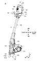
図1は第1の実施の形態に係る鉄筋結束機1Aの内部構成を示す側面図であり、図2は鉄筋結束機1Aの外観構成を示す側面図である。図4は鉄筋結束機1Aの外観構成を示す正面図、図5はその背面図、図6及び図7は斜視図、図8は平面図である。
<First embodiment>
FIG. 1 is a side view showing the internal configuration of the reinforcing
[鉄筋結束機1Aの構成例]
鉄筋結束機1Aは、操作者が把持可能な一対のグリップ120R,120Lを含むハンドル部122を有する第1本体部100と、ワイヤWを結束対象物の周囲に沿ってカールさせるカールガイド230A及びカールガイド230AによりカールされたワイヤWを保持して捩じる捩り部250とを有する第2本体部200と、第1本体部100と第2本体部200とを連結する長尺状の連結部300とを備える。
[Configuration example of the reinforcing
The
第1の実施の形態では、カールガイド230Aが設けられている側を鉄筋結束機1Aの先端側又は下側、その反対側、すなわち第1本体部100の端部側を鉄筋結束機1Aの基端側又は上側とする。また、鉄筋結束機1Aの上下方向に直交する方向であって、グリップ120R,120Lが位置する側をそれぞれ鉄筋結束機1Aの側方とし、グリップ120R側を鉄筋結束機1Aの右側、グリップ120L側を鉄筋結束機1Aの左側とする。さらに、鉄筋結束機1Aの上下方向及び左右方向に直交する方向であって、グリップ120R,120Lを把持する操作者が立つ側を鉄筋結束機1Aの操作者側又は背面側とし、その反対側を鉄筋結束機1Aの正面側とする。
In the first embodiment, the side on which the
第1本体部100は、第1筐体102と、第1筐体102に取り付けられ、一対のグリップ120R,120Lを有するハンドル部122と、第1筐体102に設けられ、バッテリ142を装着可能なバッテリ装着部140とを備える。第1筐体102は、先端側が連結部300に連結され、基端側には鉄筋結束機1Aの各種動作条件を設定するための設定部150が設けられる。
The first
ハンドル部122は、図6及び図7に示すように、連結部300の軸線方向D3から見たときに、U字状又はM字状の長尺部材で構成され、両端側にそれぞれグリップ120R,120Lを有する。グリップ120R,120Lの間にはグリップ連結部121があり、グリップ連結部121が第1筐体102に取り付けられる。グリップ120R,120Lの少なくとも一方には、結束動作を開始するための操作スイッチ160(図1参照)が設けられる。なお、ハンドル部122は、連結部300の軸線方向D3から見たときに直線状あるいは、正面又は背面方向から見たときにU字状又はM字状等、様々な形状を採用することができる。
As shown in FIGS. 6 and 7, the
グリップ120R,120Lは、図4及び図5に示すように、操作者がグリップ120R,120Lを把持して操作する場合における操作者側から見て、連結部300の軸線A3又は軸線A3の延長線の両側に設けられる。グリップ120Rは操作者側から見て軸線A3の右側に配置され、グリップ120Lは操作者側から見て軸線A3の左側に配置される。
As shown in FIGS. 4 and 5, the
バッテリ装着部140は、ハンドル部122の上方に位置するようにして第1筐体102に設けられる。また、図2、図4及び図8に示すように、バッテリ装着部140は、一対のグリップ120R,120Lの幅方向(一対のグリップ120R,120Lの並ぶ方向)D4におけるそれぞれの最外端ER,ELに接し、かつ捩り軸253と直交する第1仮想面V1に直交する一対の第2仮想面V2R,V2Lの間に配置される。第1の実施の形態では、バッテリ装着部140は、連結部300の軸線方向D3から見たときに一対のグリップ120R,120Lの間に配置される。また、バッテリ装着部140の好適な配置位置としては、グリップ120R,120Lが連結部300の軸線A1に対して左右対称となる位置に配置されるので、軸線方向D3から見てグリップ120Rの軸線A2R上の位置P1とグリップ120Lの軸線A2L上の位置P2との間の中間位置P3を含む位置である。さらにバッテリ装着部140は、図1、図2及び図4に示すように、連結部300の軸線A1の延長線上に配置されてもよい。
The
バッテリ装着部140は、図2等に示すように、カールガイド230Aの先端部を重力方向に向けた場合における重力方向を下側としたとき、グリップ120R,120Lよりも上側に配置される。バッテリ装着部140は、第1本体部100の第1筐体102の正面側に装着口141を有し、連結部300の軸線A1に対して直交又は略直交する方向からバッテリ142を装着可能に構成される。なお、第1筐体102の上面側に装着口141を設け、バッテリ装着部140を連結部300の軸線方向D3又は略軸線方向から装着可能に構成することもできる。
As shown in FIG. 2 and the like, the
設定部150は、ワイヤWの巻き数やワイヤWの捩りトルクの調整等を行うための部位であり、例えばダイヤル式や押ボタン式のスイッチなどで構成される。
The
第2本体部200は、図1に示すように、第2筐体(筐体)202と、ワイヤWが巻かれたワイヤリール211を収容するリール収容部210と、リール収容部210に収容されたワイヤリール211からワイヤWを引き出して送るワイヤ送り部220と、ワイヤWに巻き癖を付けて結束対象物の周囲に沿ってカールさせるカールガイド230Aと、カールガイド230AによりカールされたワイヤWを切断する図示しない切断部と、カールガイド230Aによりカールされるとともに切断部により切断されたワイヤWを保持して捩じる捩り部250とを備える。第2筐体202の先端部にはカールガイド230Aが設けられ、第2筐体202の内部には、ワイヤ送り部220、切断部及び捩り部250が収容される。
As shown in FIG. 1, the second
ワイヤ送り部220は、リール収容部210とカールガイド230Aとの間に設けられ、ワイヤを送るための一対の送りギアを有する。ワイヤ送り部220の一対の送りギアは、図示しないモータの駆動により正回転及び逆回転可能に構成される。これにより、送りギアを正回転させるとワイヤWをカールガイド230A側に送ることが可能となり、送りギアを逆回転させるとワイヤWをリール収容部210側に引き戻し可能となる。
The
カールガイド230Aは、鉄筋Sを挿入可能な開口260を有し、この開口260に挿入された鉄筋Sの周囲に沿ってワイヤWをカールさせる。カールガイド230Aは、第2筐体202の先端部からさらに前方(第1方向D1)に突出して設けられ、一対のガイド部、すなわち第1ガイド部231A及び第2ガイド部232Aにより構成される。第1ガイド部231A及び第2ガイド部232Aは、第1方向D1と直交する第2方向D2に開口260を構成する所定の間隔Lを空けて配置される。第1ガイド部231Aは、ワイヤ送り部220より送られてきたワイヤWの進行方向を規制して、ワイヤWに巻き癖を付ける。第2ガイド部232Aは、第1ガイド部231Aにより巻き癖が付けられたワイヤWを受けて捩り部250に誘導する。鉄筋Sを結束する場合には、第1ガイド部231Aと第2ガイド部232Aとの間の開口260に鉄筋Sを挿入する。
The
第2筐体202の先端側であって、第1ガイド部231Aと第2ガイド部232Aとの間には、第2筐体202の先端側端部を覆うカバー部206と、鉄筋Sが当接することで第2ガイド部232Aを移動させるコンタクト部材233とが設けられる。
Between the
カバー部206は、金属の板材等で構成され、図3A及び図3Bに示すように、第1ガイド部231Aの基端側と第2ガイド部232Aの基端側との間で、第2筐体202の下側の端部を覆うように取り付けられる。
The
コンタクト部材233は、カバー部206に取り付けられた軸236に回転可能に支持される。コンタクト部材233は、ドッグレッグ(くの字)状の部材であり、軸236を挟んで第1ガイド部231A側に延びる一対の当接部234(図3A等では一方の当接部のみを示す)と、第2ガイド部232A側に延びる押圧部235とを有する。
The
当接部234は開口260に挿入された鉄筋Sが当接可能な位置に配置され、押圧部235は第2ガイド部232Aに接している。コンタクト部材233は、当接部234が鉄筋Sに押し付けられて第1方向D1とは反対方向に移動すると、軸236を支点に回転する。当接部234が鉄筋Sに押し付けられることでコンタクト部材233が回動すると、押圧部235は、第2ガイド部232Aを第1ガイド部231Aに近づく方向へ押す。これにより、第2ガイド部232Aは第1ガイド部231Aに対して開いた開位置から閉じた閉位置に移動する。このように、当接部234に鉄筋Sが当接するまでは、第2ガイド部232Aが第1ガイド部231Aに対して開いているため、鉄筋Sをカールガイド230Aの開口260に挿入し易くなる。特に、第1の実施の形態のように全長の長い鉄筋結束機1Aでは、結束位置が操作者から離れているため、鉄筋Sを挿入し難い。このため、結束時に第2ガイド部232Aが開いていると、鉄筋Sをカールガイド230Aの開口260に挿入し易くなる。
The
捩り部250は、捩りモータ251と、捩りモータ251の減速及びトルクの増幅を行う減速機構252と、減速機構252に接続され、捩りモータ251の回転により回転する捩り軸253と、捩り軸253の回転動作で変位する可動部材254と、可動部材254の先端側に突出し、ワイヤWを保持して捩じる保持部255とを備える。
The
捩り軸253の外周面と可動部材254の内周面には、それぞれねじが形成され、捩り軸253のねじが可動部材254のねじに螺合している。可動部材254は、回転が規制された状態で、捩り軸253が回転すると、前後方向へ移動し、回転の規制が解除されると、捩り軸253と一体的に回転する。
Screws are respectively formed on the outer peripheral surface of the
保持部255は、ワイヤWを保持するための複数の爪部を有する。保持部255は、可動部材254の前後方向の移動に合わせて開閉し、可動部材254の回転動作に合わせて回転する。
The holding
連結部300は、中空の長尺部材であり、内部に配線が敷設される。連結部300は、第1本体部100及び第2本体部200の径よりも細い棒状の部材から構成される。連結部300の長さは、例えば操作者の平均的な身長等に応じて選定される。連結部300には、例えばアルミニウム、ステンレス等の金属、樹脂、炭素繊維等の非金属を用いることができる。これにより、鉄筋結束機1A全体の軽量化を図ることができる。
The
連結部300の基端側(上端部)は第1筐体102に取り付けられ、連結部300の先端側(下端部)は第2筐体202に取り付けられる。連結部300は、第1本体部100及び第2本体部200に対して着脱可能に構成することができる。
The proximal end (upper end) of the connecting
連結部300の内部に敷設される配線は第1本体部100のバッテリ142や操作スイッチ160、第2本体部200の制御装置などに接続される。これにより、第1本体部100と第2本体部200との間で電気信号の通信が可能となり、第1本体部100から第2本体部200への電力供給が可能となる。
The wiring laid inside the connecting
[鉄筋結束機1Aの動作例]
鉄筋Sの結束を行う場合、操作者は、鉄筋Sを第1ガイド部231Aと第2ガイド部232Aとの間の開口260に挿入し、鉄筋Sをコンタクト部材233の当接部234に押し当てる。これに伴い、コンタクト部材233が軸236を支点として回転し、押圧部235により第2ガイド部232Aが押され、第2ガイド部232Aが開位置から閉位置に移動する。操作者は、第2ガイド部232Aが閉じた状態で操作スイッチ160をオンすることで、結束動作が開始される。
[Operation example of the reinforcing
When binding the rebar S, the operator inserts the rebar S into the
操作スイッチ160をオンすると、ワイヤ送り部220の一対の送りギアは、ワイヤWを挟持して回転し、ワイヤリール211からワイヤWをカールガイド230A側に送り出す。ワイヤ送り部220で送られたワイヤWは、カールガイド230Aによってカール状に癖付けされた後、カール状のワイヤWが鉄筋Sの周囲に複数回巻かれる。鉄筋Sの周囲にワイヤWを巻く回数(巻き数)は、設定部150により設定可能である。鉄筋Sの周囲に複数回巻かれたワイヤWは切断部により切断された後、捩り部250により捩じられる。このような動作により、鉄筋SをワイヤWによって結束することができる。
When the
[第1の実施の形態の効果]
第1本体部100に設けられるグリップ120R,120Lと第2本体部200とは離れた位置関係となり、これに伴い、鉄筋結束機1Aの第2本体部200側の重心もグリップ120R,120Lから離れる傾向となる。つまり、グリップ120R,120Lの配置位置は、鉄筋結束機1Aの重心位置と一致していない。
[Effect of First Embodiment]
The
ここで、操作者は、不安定な鉄筋上で作業を行う場合がある。この場合、操作者は、不安定な鉄筋上をできるだけ移動することなく鉄筋を結束したいと考える。このため、操作者は、立ち位置を変えずに、カールガイド230Aが届く範囲の鉄筋を第2本体部200を前後左右に振りながら結束することになる。しかしこの場合、第2本体部200は重量が重いため、操作者の腕や肩などにかかる負担が大きくなるという問題がある。
Here, the operator may work on an unstable reinforcing bar. In this case, the operator wants to bind the rebar without moving as much as possible on the unstable rebar. For this reason, the operator binds the rebar within the reach of the
第1の実施の形態によれば、一対のグリップ120R,120Lを操作者側から見て連結部300の軸線A1等の両側に設けるので、操作者は両手でグリップ120R,120Lを把持できる。これにより、立ち位置を変えずに、第2本体部200を前後左右に振りながら作業を行う場合であっても、操作者の腕や肩等にかかる負担を大幅に軽減することができる。
According to the first embodiment, the pair of
また、第1の実施の形態によれば、連結部300の軸線方向D3から見たときに、一対のグリップ120R,120Lの間にバッテリ装着部140を配置するので、バッテリ142を操作者の近傍に配置することができる。そのため、操作者の操作支点(回転支点)の近傍に重量物のバッテリ142を配置できるため、操作者は鉄筋結束機1Aの第2本体部200側を操作支点として鉄筋結束機1Aを前後左右に振りやすい。これにより、操作性の向上を図ることができる。
Further, according to the first embodiment, when viewed from the axial direction D3 of the connecting
また、第1の実施の形態によれば、バッテリ装着部140を連結部300の軸線A1上に配置するので、重量バランスがより向上する。また、バッテリ142を装着した際にバッテリ142が第1筐体102から正面側に張り出してしまうことを防止できる。つまり、連結部300の軸線方向D3から第2本体部200側を見た場合に、バッテリ142がカールガイド230Aよりも正面側(外側)に張り出さない構成とすることができる。これにより、結束作業時における操作者の視認性を確保することができる。
Further, according to the first embodiment, since the
第1の実施の形態によれば、バッテリ装着部140をグリップ120R,120Lの上方に配置したので、バッテリ142の着脱が容易になる。
According to the first embodiment, since the
<第1の実施の形態の変形例>
なお、第1の実施の形態に係る鉄筋結束機1Aでは、操作スイッチ160のオン操作により結束動作を開始するように構成したが、これに限定されることはない。例えば、操作スイッチ160のオン操作により結束動作を開始するのではなく、コンタクト部材233に鉄筋Sが当接したことを検知したら結束動作を開始するようにしてもよい。この場合、鉄筋Sを結束するのに、操作スイッチ160をオンする必要がないので、作業性が向上する。
<Modification of First Embodiment>
In the
また、コンタクト部材233に鉄筋Sが当接しただけでは結束動作を開始せず、操作スイッチ160をオンした状態でコンタクト部材233に鉄筋Sが当接した場合に結束動作を開始するようにしてもよい。この場合、操作スイッチ160をオンした状態であれば、次々に鉄筋Sを結束できるため作業性に優れ、しかも操作スイッチ160をオンしていなければコンタクト部材に鉄筋Sを当接させても結束動作を開始しないので、不用意な結束動作の実行を抑制できる。なお、この変形例の具体的な構造としては、例えば、コンタクト部材233の回転動作に応じてオン/オフが切り替わる作動スイッチをコンタクト部材233の近傍に配置し、この作動スイッチがオンになったら結束動作を実行するようにしてもよい。作動スイッチには、例えば、機械的スイッチや、ホールIC等のセンサを用いることができる。
Further, the binding operation is not started only by the contact of the rebar S with the
鉄筋Sの結束を行う場合、操作者は、操作スイッチ160をオンした状態で、鉄筋Sを第1ガイド部231Aと第2ガイド部232Aとの間の開口260に挿入する。これにより、コンタクト部材233の当接部234に鉄筋Sが押し当てられ、コンタクト部材233が軸236を支点として回転して例えば作動位置に移動すると、第2スイッチがオンする。第2本体部200内に設けられた図示しない制御部は、操作スイッチ160及び作動スイッチの両方がオン状態である場合に、結束動作を開始する。第2ガイド部232Aは、コンタクト部材233の回転により開位置から閉位置に移動する。
When binding the rebar S, the operator inserts the rebar S into the
<第2の実施の形態>
図9は第2の実施の形態に係る鉄筋結束機1Bの内部構成を示す側面図である。第2の実施の形態の鉄筋結束機1Bは、コンタクト部材233を備えていない点において第1の実施の形態に係る鉄筋結束機1Aと異なる。鉄筋結束機1Bは、コンタクト部材233を備えていないので、開口260に鉄筋Sが挿抜されても、カールガイド230Bは開閉しない。なお、鉄筋結束機1Bは、コンタクト部材233を備えていない点を除き、鉄筋結束機1Aと同様の構成である。
<Second embodiment>
FIG. 9 is a side view showing an internal configuration of a reinforcing
なお、本発明の技術範囲は、上述した実施形態に限定されるものではなく、本発明の趣旨を逸脱しない範囲において、上述した実施形態に種々の変更を加えたものを含む。例えば、バッテリ装着部140を連結部300の軸線A1上に設けた例について説明したが、必ずしも軸線A1上に設けなくてもよい。例えば、図8に示すように、グリップ120R,120Lの中間位置P3を含み、グリップ120R,120Lの各軸線A2R,A2Lに平行な仮想軸線A4上にバッテリ装着部140を設けることもできる。また、中間位置P3から多少ずれた位置にバッテリ装着部140を設けてもよい。
Note that the technical scope of the present invention is not limited to the above-described embodiments, and includes various modifications of the above-described embodiments without departing from the spirit of the present invention. For example, although the example in which the
バッテリ装着部140をグリップ120R,120Lと連結部300との間に配置してもよい。バッテリ装着部140をこの位置に配置することで、グリップ120R,120Lの上方のスペースを省けるので、鉄筋結束機1Aの全長の短縮化、視認性の向上を果すことができる。
The
1A 鉄筋結束機(結束機)
100 第1本体部
102 第1筐体
120R,120L グリップ
140 バッテリ装着部
142 バッテリ
200 第2本体部
202 第2筐体
220 ワイヤ送り部
230A,230B カールガイド
231A 第1ガイド部
232A 第2ガイド部
250 捩り部
253 捩り軸
300 連結部
A1 連結部の軸線
A3 捩り軸の軸線
S 鉄筋(結束対象物)
V1 第1仮想面
V2R,V2L 第2仮想面
W ワイヤ
1A Rebar binding machine (bundling machine)
100 first
V1 First virtual plane V2R, V2L Second virtual plane W Wire
Claims (9)
前記ワイヤを結束対象物の周囲に沿ってカールさせるカールガイドと、前記カールされた前記ワイヤを捩じる捩り軸を含む捩り部とを有する第2本体部と、
前記第1本体部と前記第2本体部とを連結する連結部と
を備え、
前記グリップは、前記操作者が前記グリップを把持して操作する場合における前記操作者側から見て、前記連結部の軸線又は前記軸線の延長線の両側に設けられる
結束機。 A first main body having a pair of grips that can be gripped by an operator;
A second body portion having a curl guide for curling the wire along the periphery of the binding object, and a torsion portion including a torsion axis for twisting the curled wire;
A connection portion that connects the first body portion and the second body portion,
The binding machine, wherein the grip is provided on both sides of an axis of the connecting portion or an extension of the axis when viewed from the operator side when the operator grips and operates the grip.
請求項1に記載の結束機。 The binding machine according to claim 1, wherein the first main body has a battery mounting portion to which a battery can be mounted.
バッテリ装着部は、前記一対のグリップの前記幅方向におけるそれぞれの最外端に接し、かつ前記捩り軸と直交する第1仮想面と直交する一対の第2仮想面の間に配置される
請求項2に記載の結束機。 When the direction in which the pair of grips are arranged is the width direction,
The battery mounting portion is disposed between a pair of second virtual surfaces that are in contact with outermost ends of the pair of grips in the width direction and that are orthogonal to a first virtual surface that is orthogonal to the torsion axis. 3. The binding machine according to 2.
請求項2から4のいずれかに記載の結束機。 The binding machine according to any one of claims 2 to 4, wherein the battery mounting portion is disposed on an extension of an axis of the connecting portion.
請求項2から5のいずれかに記載の結束機。 The binding machine according to any one of claims 2 to 5, wherein the battery mounting portion is disposed between the grip and the connecting portion.
請求項2から5のいずれかに記載の結束機。 The binding device according to any one of claims 2 to 5, wherein the battery mounting unit is disposed above the grip when the direction of gravity is downward when the tip of the curl guide is oriented in the direction of gravity. .
請求項2から7のいずれかに記載の結束機。 The binding machine according to any one of claims 2 to 7, wherein the battery mounting portion is configured to be capable of mounting the battery from a direction orthogonal or substantially orthogonal to an axis of the connecting portion.
請求項2から7のいずれかに記載の結束機。 The binding machine according to any one of claims 2 to 7, wherein the battery mounting portion is configured to be capable of mounting the battery from an axial direction or a substantially axial direction of the connecting portion.
Priority Applications (17)
| Application Number | Priority Date | Filing Date | Title |
|---|---|---|---|
| JP2018168251A JP7163679B2 (en) | 2018-09-07 | 2018-09-07 | binding machine |
| US17/274,149 US12370596B2 (en) | 2018-09-07 | 2019-09-05 | Binding machine |
| EP19857979.9A EP3848292B1 (en) | 2018-09-07 | 2019-09-05 | Binding machine |
| PCT/JP2019/035093 WO2020050388A1 (en) | 2018-09-07 | 2019-09-05 | Binding machine |
| CN201980057794.6A CN112638778A (en) | 2018-09-07 | 2019-09-05 | Binding machine |
| US17/273,337 US12060719B2 (en) | 2018-09-07 | 2019-09-05 | Binding machine |
| ES19857979T ES2973053T3 (en) | 2018-09-07 | 2019-09-05 | binder |
| EP19856826.3A EP3848533B1 (en) | 2018-09-07 | 2019-09-05 | Binding machine |
| PL19857979.9T PL3848292T3 (en) | 2018-09-07 | 2019-09-05 | Binding machine |
| CN202510410389.5A CN120139507A (en) | 2018-09-07 | 2019-09-05 | Strapping Machine |
| ES19856826T ES2988813T3 (en) | 2018-09-07 | 2019-09-05 | Binder |
| CN201980057822.4A CN112654757A (en) | 2018-09-07 | 2019-09-05 | Binding machine |
| PCT/JP2019/035090 WO2020050386A1 (en) | 2018-09-07 | 2019-09-05 | Binding machine |
| PL19856826.3T PL3848533T3 (en) | 2018-09-07 | 2019-09-05 | Binding machine |
| TW108132295A TWI842738B (en) | 2018-09-07 | 2019-09-06 | Strapping Machine |
| TW108132292A TWI860298B (en) | 2018-09-07 | 2019-09-06 | Bundling Machine |
| US19/265,208 US20250339893A1 (en) | 2018-09-07 | 2025-07-10 | Binding machine |
Applications Claiming Priority (1)
| Application Number | Priority Date | Filing Date | Title |
|---|---|---|---|
| JP2018168251A JP7163679B2 (en) | 2018-09-07 | 2018-09-07 | binding machine |
Publications (2)
| Publication Number | Publication Date |
|---|---|
| JP2020041299A true JP2020041299A (en) | 2020-03-19 |
| JP7163679B2 JP7163679B2 (en) | 2022-11-01 |
Family
ID=69722886
Family Applications (1)
| Application Number | Title | Priority Date | Filing Date |
|---|---|---|---|
| JP2018168251A Active JP7163679B2 (en) | 2018-09-07 | 2018-09-07 | binding machine |
Country Status (8)
| Country | Link |
|---|---|
| US (1) | US12060719B2 (en) |
| EP (1) | EP3848533B1 (en) |
| JP (1) | JP7163679B2 (en) |
| CN (2) | CN120139507A (en) |
| ES (1) | ES2988813T3 (en) |
| PL (1) | PL3848533T3 (en) |
| TW (1) | TWI842738B (en) |
| WO (1) | WO2020050386A1 (en) |
Families Citing this family (4)
| Publication number | Priority date | Publication date | Assignee | Title |
|---|---|---|---|---|
| US12370596B2 (en) | 2018-09-07 | 2025-07-29 | Max Co., Ltd. | Binding machine |
| JP7354687B2 (en) | 2018-09-07 | 2023-10-03 | マックス株式会社 | tying machine |
| JP7275506B2 (en) | 2018-09-07 | 2023-05-18 | マックス株式会社 | binding machine |
| JP7625883B2 (en) | 2021-02-15 | 2025-02-04 | マックス株式会社 | Binding machine |
Citations (5)
| Publication number | Priority date | Publication date | Assignee | Title |
|---|---|---|---|---|
| JPS63191719A (en) * | 1987-01-27 | 1988-08-09 | 松下電工株式会社 | Bundling machine |
| JPH07290177A (en) * | 1994-04-22 | 1995-11-07 | Toyota Kihan:Kk | Rebar binding machine |
| JPH0913677A (en) * | 1995-06-30 | 1997-01-14 | Max Co Ltd | Safety device in reinforcement binding machine |
| CN105386602A (en) * | 2005-10-10 | 2016-03-09 | 建筑设备私人有限公司 | Apparatus for binding objects together |
| WO2018131218A1 (en) * | 2017-01-10 | 2018-07-19 | 株式会社マキタ | Binding machine |
Family Cites Families (35)
| Publication number | Priority date | Publication date | Assignee | Title |
|---|---|---|---|---|
| US4354535A (en) * | 1980-04-21 | 1982-10-19 | Powell Robert Y | Hand-held automatic wire binding tool |
| SE9003176D0 (en) * | 1990-10-04 | 1990-10-04 | Peter Hoyaukin | SEAT AND MACHINE CONNECTING CROSSING RODS |
| JP3393684B2 (en) * | 1993-08-16 | 2003-04-07 | 株式会社エスディーコーポレーション | Article binding method and binding apparatus |
| JP3604695B2 (en) | 1994-06-24 | 2004-12-22 | テイロン インダストリーズ エルエルシー | Wire tie with drive mechanism |
| SE504740C2 (en) | 1995-08-18 | 1997-04-14 | Peter Hoyaukin | Machine for connecting elongated objects |
| GB0022557D0 (en) * | 2000-09-14 | 2000-11-01 | Black & Decker Inc | String trimmer |
| US20040229195A1 (en) | 2003-03-18 | 2004-11-18 | Leapfrog Enterprises, Inc. | Scanning apparatus |
| SE523239C2 (en) * | 2003-03-18 | 2004-04-06 | Peter Hoyaukin | Tying machine, especially for connecting reinforcing bars or electric cables, comprises claws, feed device and rotary part for forming wire bracket around object and tying its arms |
| US7290570B1 (en) * | 2003-04-21 | 2007-11-06 | Spikes Larry W | Twist attachment device |
| US20060125805A1 (en) | 2004-03-17 | 2006-06-15 | James Marggraff | Method and system for conducting a transaction using recognized text |
| US7853193B2 (en) | 2004-03-17 | 2010-12-14 | Leapfrog Enterprises, Inc. | Method and device for audibly instructing a user to interact with a function |
| US20060127872A1 (en) | 2004-03-17 | 2006-06-15 | James Marggraff | Method and device for associating a user writing with a user-writable element |
| US20060078866A1 (en) | 2004-03-17 | 2006-04-13 | James Marggraff | System and method for identifying termination of data entry |
| US20060033725A1 (en) | 2004-06-03 | 2006-02-16 | Leapfrog Enterprises, Inc. | User created interactive interface |
| US20060077184A1 (en) | 2004-03-17 | 2006-04-13 | James Marggraff | Methods and devices for retrieving and using information stored as a pattern on a surface |
| US20060067576A1 (en) | 2004-03-17 | 2006-03-30 | James Marggraff | Providing a user interface having interactive elements on a writable surface |
| US20060066591A1 (en) | 2004-03-17 | 2006-03-30 | James Marggraff | Method and system for implementing a user interface for a device through recognized text and bounded areas |
| US7831933B2 (en) | 2004-03-17 | 2010-11-09 | Leapfrog Enterprises, Inc. | Method and system for implementing a user interface for a device employing written graphical elements |
| US7453447B2 (en) | 2004-03-17 | 2008-11-18 | Leapfrog Enterprises, Inc. | Interactive apparatus with recording and playback capability usable with encoded writing medium |
| US7347276B2 (en) * | 2004-08-23 | 2008-03-25 | Tci97 Inc. | Adjustable garden tool |
| US7069962B2 (en) * | 2004-08-27 | 2006-07-04 | Dara Cheng | Wire cutting and twisting tool with spool assembly and manual wire feeding mechanism |
| US20090145271A1 (en) * | 2006-06-26 | 2009-06-11 | Par Martinsson | Handle member |
| GB0621428D0 (en) * | 2006-10-27 | 2006-12-06 | Tymatic Ltd | Consumables authentication |
| US9591809B2 (en) * | 2007-02-06 | 2017-03-14 | Mtd Products Inc | Split power tool |
| CN101353088B (en) | 2008-06-20 | 2010-07-28 | 蔡昌开 | Reinforced bar binding machine |
| DE102010015218A1 (en) | 2010-04-16 | 2011-10-20 | Wacker Neuson Se | Wire binding device with positioning device |
| US11267038B2 (en) | 2015-07-22 | 2022-03-08 | Max Co., Ltd. | Binding machine |
| JP6632883B2 (en) | 2015-12-25 | 2020-01-22 | 株式会社マキタ | Electric work machine |
| JP2017189822A (en) | 2016-04-11 | 2017-10-19 | 株式会社マルイ | Hand-held electric power tool, electric binding machine with attachment and extension attachment |
| JP6972553B2 (en) * | 2016-12-29 | 2021-11-24 | マックス株式会社 | Cable ties |
| JP6953159B2 (en) | 2017-03-29 | 2021-10-27 | バンドー化学株式会社 | Polyolefin resin film and laminate |
| US10688647B2 (en) * | 2017-05-19 | 2020-06-23 | The Toro Company | Lawn and garden tool with boom having adjustable length and detachable boom sections |
| US11365552B2 (en) * | 2017-06-07 | 2022-06-21 | Max Co., Ltd. | Binding machine |
| TWM552524U (en) | 2017-08-30 | 2017-12-01 | 大葉大學 | Rebar-tying machine capable of being operated in standing or squatting position |
| CN207314873U (en) | 2017-10-17 | 2018-05-04 | 黑龙江省睿智方圆建筑工程有限公司 | A kind of building iron fast bunding machine |
-
2018
- 2018-09-07 JP JP2018168251A patent/JP7163679B2/en active Active
-
2019
- 2019-09-05 US US17/273,337 patent/US12060719B2/en active Active
- 2019-09-05 EP EP19856826.3A patent/EP3848533B1/en active Active
- 2019-09-05 CN CN202510410389.5A patent/CN120139507A/en active Pending
- 2019-09-05 WO PCT/JP2019/035090 patent/WO2020050386A1/en not_active Ceased
- 2019-09-05 ES ES19856826T patent/ES2988813T3/en active Active
- 2019-09-05 CN CN201980057822.4A patent/CN112654757A/en active Pending
- 2019-09-05 PL PL19856826.3T patent/PL3848533T3/en unknown
- 2019-09-06 TW TW108132295A patent/TWI842738B/en active
Patent Citations (5)
| Publication number | Priority date | Publication date | Assignee | Title |
|---|---|---|---|---|
| JPS63191719A (en) * | 1987-01-27 | 1988-08-09 | 松下電工株式会社 | Bundling machine |
| JPH07290177A (en) * | 1994-04-22 | 1995-11-07 | Toyota Kihan:Kk | Rebar binding machine |
| JPH0913677A (en) * | 1995-06-30 | 1997-01-14 | Max Co Ltd | Safety device in reinforcement binding machine |
| CN105386602A (en) * | 2005-10-10 | 2016-03-09 | 建筑设备私人有限公司 | Apparatus for binding objects together |
| WO2018131218A1 (en) * | 2017-01-10 | 2018-07-19 | 株式会社マキタ | Binding machine |
Also Published As
| Publication number | Publication date |
|---|---|
| EP3848533B1 (en) | 2024-08-21 |
| TW202019770A (en) | 2020-06-01 |
| WO2020050386A1 (en) | 2020-03-12 |
| PL3848533T3 (en) | 2025-01-13 |
| TWI842738B (en) | 2024-05-21 |
| ES2988813T3 (en) | 2024-11-21 |
| CN112654757A (en) | 2021-04-13 |
| EP3848533A1 (en) | 2021-07-14 |
| EP3848533C0 (en) | 2024-08-21 |
| EP3848533A4 (en) | 2022-05-04 |
| JP7163679B2 (en) | 2022-11-01 |
| US20210340781A1 (en) | 2021-11-04 |
| CN120139507A (en) | 2025-06-13 |
| US12060719B2 (en) | 2024-08-13 |
Similar Documents
| Publication | Publication Date | Title |
|---|---|---|
| WO2020050386A1 (en) | Binding machine | |
| US11346107B2 (en) | Rebar tying tool | |
| WO2020050385A1 (en) | Binding machine | |
| JP7354688B2 (en) | tying machine | |
| JP7310873B2 (en) | binding machine | |
| JP2018109296A (en) | Binding machine | |
| JP6790823B2 (en) | Cable ties | |
| JP6834485B2 (en) | Cable ties | |
| CN110155402B (en) | Bundling machine | |
| JP7326997B2 (en) | binding machine | |
| JP2018108850A (en) | Binding machine | |
| JP2020150620A (en) | Rotation drive device and rotary operation rod equipped with it | |
| JP2024115422A (en) | Power tools |
Legal Events
| Date | Code | Title | Description |
|---|---|---|---|
| A621 | Written request for application examination |
Free format text: JAPANESE INTERMEDIATE CODE: A621 Effective date: 20210604 |
|
| RD02 | Notification of acceptance of power of attorney |
Free format text: JAPANESE INTERMEDIATE CODE: A7422 Effective date: 20220114 |
|
| A131 | Notification of reasons for refusal |
Free format text: JAPANESE INTERMEDIATE CODE: A131 Effective date: 20220510 |
|
| A521 | Request for written amendment filed |
Free format text: JAPANESE INTERMEDIATE CODE: A523 Effective date: 20220708 |
|
| A131 | Notification of reasons for refusal |
Free format text: JAPANESE INTERMEDIATE CODE: A131 Effective date: 20220802 |
|
| A521 | Request for written amendment filed |
Free format text: JAPANESE INTERMEDIATE CODE: A523 Effective date: 20220905 |
|
| TRDD | Decision of grant or rejection written | ||
| A01 | Written decision to grant a patent or to grant a registration (utility model) |
Free format text: JAPANESE INTERMEDIATE CODE: A01 Effective date: 20220920 |
|
| A61 | First payment of annual fees (during grant procedure) |
Free format text: JAPANESE INTERMEDIATE CODE: A61 Effective date: 20221003 |
|
| R150 | Certificate of patent or registration of utility model |
Ref document number: 7163679 Country of ref document: JP Free format text: JAPANESE INTERMEDIATE CODE: R150 |