JP2020042575A - Information processing apparatus, positioning method, and program - Google Patents
Information processing apparatus, positioning method, and program Download PDFInfo
- Publication number
- JP2020042575A JP2020042575A JP2018169820A JP2018169820A JP2020042575A JP 2020042575 A JP2020042575 A JP 2020042575A JP 2018169820 A JP2018169820 A JP 2018169820A JP 2018169820 A JP2018169820 A JP 2018169820A JP 2020042575 A JP2020042575 A JP 2020042575A
- Authority
- JP
- Japan
- Prior art keywords
- model
- coordinate system
- orientation
- unit
- camera
- Prior art date
- Legal status (The legal status is an assumption and is not a legal conclusion. Google has not performed a legal analysis and makes no representation as to the accuracy of the status listed.)
- Pending
Links
Images


Landscapes
- Processing Or Creating Images (AREA)
- Image Analysis (AREA)
Abstract
Description
本発明は、情報処理装置、位置合わせ方法、及びプログラムに関する。 The present invention relates to an information processing device, a positioning method, and a program.
近年、AR(Augmented Reality)技術が注目されつつある。ARは、例えば、人が知覚する現実環境をコンピュータにより拡張する技術、およびコンピュータにより拡張された現実環境そのものを指す用語として用いられる。ARでは、例えば、現実世界をベースとして、仮想物体を現実世界に映し出して、現実世界の一部を拡張した映像を映し出すことができる。ARは、例えば、仮想空間がベースとなり、現実世界が入り込まないVR(Virtual Reality:仮想現実)と対比されて用いられる場合がある。 In recent years, AR (Augmented Reality) technology has been receiving attention. AR is used as a term that refers to, for example, a technology of extending a real environment perceived by humans with a computer, and a real environment itself extended by a computer. In AR, for example, a virtual object can be projected in the real world based on the real world, and an image in which a part of the real world is extended can be projected. The AR may be used, for example, in comparison with a VR (Virtual Reality) that is based on a virtual space and does not enter the real world.
AR技術では、仮想物体を、カメラの動きに従って、現実世界に重畳して3次元的に変化させている。例えば、AR技術を適用する情報処理装置では、各画像フレームにおいて、現実世界に重畳させる仮想物体の位置を、カメラの位置(又は方向)と姿勢(又は回転)に応じて決定する。仮想物体の位置を、カメラの位置と姿勢に応じて画像座標系へと投影したときに、現実世界の座標系から画像座標系へ、座標系を変換する情報を求めることを、例えば、「位置合わせ」と称する場合がある。 In the AR technology, a virtual object is three-dimensionally superimposed on the real world according to the movement of a camera. For example, in an information processing apparatus to which the AR technology is applied, in each image frame, the position of a virtual object to be superimposed on the real world is determined according to the position (or direction) and attitude (or rotation) of the camera. When projecting the position of the virtual object onto the image coordinate system according to the position and orientation of the camera, obtaining information for converting the coordinate system from the real world coordinate system to the image coordinate system may be performed, for example, by using the `` position It may be called "matching".
位置合わせの手法として、例えば、マーカーベースの位置合わせ手法がある。マーカーベースの位置合わせ手法は、例えば、2値(例えば、白と黒)の矩形のマーカーを予め用意しておき、情報処理装置において、マーカーを撮像し、撮像したマーカーの画像からマーカーの直線を検出するなどして、位置合わせを行う手法である。マーカーベースの位置合わせ手法は、例えば、既知のマーカーが用いられるため、情報処理装置では、画像から直線などを容易に検出し、位置合わせも容易に行うことが可能である。 As an alignment method, for example, there is a marker-based alignment method. In the marker-based alignment method, for example, a binary (for example, black and white) rectangular marker is prepared in advance, the marker is imaged in the information processing apparatus, and a straight line of the marker is extracted from the captured marker image. This is a method of performing position alignment by detecting. In the marker-based alignment method, for example, a known marker is used, so that the information processing apparatus can easily detect a straight line or the like from an image and can easily perform alignment.
しかし、マーカーベースの位置合わせ手法は、マーカーを別途用意することになる。そのため、マーカーベースの位置合わせ手法は、マーカーを用いない他の手法と比較して、設置コストが高くなる場合がある。 However, in the marker-based alignment method, a marker is separately prepared. For this reason, the marker-based positioning method may have a higher installation cost than other methods that do not use a marker.
そこで、位置合わせ手法に関しては、マーカーレスによる位置合わせ手法の技術がある。例えば、様々な姿勢による物体を観測して学習データを得て、メモリなどに保存し、カメラで撮影した単一視点のRGB(Red, Green, Blue)画像から、3次元6D(Degree of freedom)の被写体の位置と姿勢を学習ベースで推定する技術がある。 Therefore, as a positioning method, there is a technique of a markerless positioning method. For example, three-dimensional 6D (Degree of freedom) is obtained from a single viewpoint RGB (Red, Green, Blue) image obtained by a camera by observing objects in various postures, acquiring learning data, storing the learning data in a memory, or the like. There is a technique for estimating the position and orientation of a subject on a learning basis.
また、仮想座標系内に固定されている仮想カメラからの仮想画像を、実空間中のオブジェクトの実ビデオ画像と実質的に一致する位置までカメラを移動させて、仮想座標系の仮想モデルの位置を、実座標系のオブジェクトの位置にマッピングする技術がある。 Also, by moving the virtual image from the virtual camera fixed in the virtual coordinate system to a position substantially matching the real video image of the object in the real space, the position of the virtual model in the virtual coordinate system is moved. Is mapped to the position of the object in the real coordinate system.
この技術によれば、オブジェクトの仮想画像の、オブジェクトの実際の位置へのコレジストレーションのための改善されたシステムおよび方法を提供できる、とされる。 According to this technique, an improved system and method for co-registration of a virtual image of an object to an actual position of the object can be provided.
しかし、単一視点のRGB画像から学習ベースで被写体の位置と姿勢と推定する技術は、見た目の特徴が乏しい画像が被写体の場合、その物体の位置と姿勢を推定することが困難な場合がある。「見た目の特徴が乏しい画像」とは、例えば、コントラストの強いコーナ点やエッジ点の数が閾値よりも少ない、或いは、コントラストの強い表面の模様の数が閾値よりも少ない画像などの場合である。このような物体の画像は、画像処理で抽出可能な特徴数が閾値よりも少ない傾向にある。かかる技術では、メモリに保存した学習データに基づいて、被写体の位置と姿勢を推定しており、特徴数が閾値よりも少ない場合、RGB画像に対応する学習データをメモリから読み出しても、読み出した学習データの精度が低くなる場合がある。従って、かかる技術では、「見た目の特徴が乏しい画像」に対して、推定した被写体の位置と姿勢の精度が低くなる場合がある。 However, in the technology of estimating the position and orientation of a subject from a single viewpoint RGB image on a learning basis, it may be difficult to estimate the position and orientation of the object when the image having poor appearance characteristics is the subject. . The “image with poor appearance characteristics” is, for example, an image in which the number of corner points and edge points having strong contrast is smaller than the threshold value, or the number of patterns on the surface having strong contrast is smaller than the threshold value. . In such an image of the object, the number of features that can be extracted by image processing tends to be smaller than a threshold. In this technique, the position and orientation of the subject are estimated based on the learning data stored in the memory. If the number of features is smaller than the threshold, the learning data corresponding to the RGB image is read from the memory. The accuracy of the learning data may decrease. Therefore, in such a technique, the accuracy of the estimated position and orientation of the subject may be reduced with respect to the “image having poor appearance characteristics”.
また、固定された仮想カメラからの仮想画像を実ビデオ画像と実質的に一致させる技術は、例えば、仮想画像が固定されて表示されるため、実ビデオ画像と実質的に一致させるために、ユーザが、ある決められた1つの位置及び姿勢にカメラを移動させるようにしている。従って、かかる技術では、位置合わせの際に、カメラの移動が制限され、ユーザにとって、位置合わせが容易に行うことができない場合がある。 In addition, a technique for substantially matching a virtual image from a fixed virtual camera with a real video image is, for example, a method in which a virtual image is fixedly displayed, so that a user can substantially match a real video image. However, the camera is moved to one determined position and posture. Therefore, in such a technique, the movement of the camera is limited at the time of the alignment, and the user may not be able to easily perform the alignment.
そこで、見た目の特徴が乏しい画像であっても、位置合わせを容易に行うことが可能な情報処理装置、位置合わせ方法、及びプログラムを提供することにある。 Therefore, an object of the present invention is to provide an information processing apparatus, a positioning method, and a program that can easily perform positioning even for an image having poor appearance characteristics.
一開示は、情報処理装置の加速度データを出力する慣性センサと、前記加速度データから世界座標系における第1の重力方向を推定する重力方向推定部と、カメラ座標系におけるモデルの位置と姿勢を、カメラ座標系に対する前記第1の重力方向に応じて変化させ、カメラ座標系における前記モデルの位置と姿勢をモデル座標系における前記モデルの位置と姿勢へそれぞれ変換し、モデル座標系における前記モデルの位置と姿勢を世界座標系における前記モデルの位置と姿勢へそれぞれ変換する第1の変換行列を算出するモデル位置推定部と、カメラ座標系における前記モデルの位置と姿勢を画像座標系における前記モデルの位置に変換し、入力画像と前記モデルとを画像座標系に描画するモデル描画部と、前記モデル描画部の描画結果に従って、前記入力画像と前記モデルとを表示する表示部とを備える情報処理装置。 One disclosure is an inertial sensor that outputs acceleration data of an information processing device, a gravitational direction estimating unit that estimates a first gravitational direction in a world coordinate system from the acceleration data, and a position and orientation of a model in a camera coordinate system. Changing the position and orientation of the model in the camera coordinate system into the position and orientation of the model in the model coordinate system, respectively, by changing the position and orientation of the model in the camera coordinate system, And a model position estimating unit for calculating a first transformation matrix for converting the position and orientation into the position and orientation of the model in the world coordinate system, and the position and orientation of the model in the camera coordinate system and the position of the model in the image coordinate system. And a model drawing unit that draws the input image and the model in the image coordinate system, according to the drawing result of the model drawing unit. Te, an information processing apparatus and a display unit for displaying said model and the input image.
一開示によれば、見た目の特徴が乏しい画像であっても、位置合わせを容易に行うことが可能である。 According to an embodiment of the present disclosure, it is possible to easily perform positioning even for an image having poor appearance characteristics.
以下、本発明を実施するための形態について説明する。なお、以下の実施例は開示の技術を限定するものではない。そして、各実施の形態は、処理内容を矛盾させない範囲で適宜組み合わせることが可能である。 Hereinafter, embodiments for carrying out the present invention will be described. The following embodiments do not limit the disclosed technology. The embodiments can be appropriately combined within a range that does not contradict processing contents.
[第1の実施の形態]
<情報処理装置の構成例>
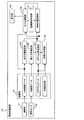
図1は情報処理装置100の構成例を表す図である。
[First Embodiment]
<Configuration example of information processing device>
FIG. 1 is a diagram illustrating a configuration example of the
情報処理装置100は、例えば、スマートフォン、ゲーム装置、設備の点検及び管理装置、ナビゲーション装置などである。
The
第1の実施の形態における情報処理装置100は、AR技術を用いて、現実世界にモデル画像(又仮想モデル、或いは3D(3-Dimension)モデル。以下、「3Dモデル」と称する場合がある。)を表示させる。情報処理装置100は、3Dモデルを用いて位置合わせを行う。この際、情報処理装置100は、見た目の特徴が乏しい物体を対象物体とする場合でも、様々なカメラ視点から、3Dモデルを用いて対象物体に対する位置合わせが可能となる。
The
本第1の実施の形態において、「位置合わせ」とは、例えば、2つの座標系を結びつける情報を算出することである。本第1の実施の形態における「位置合わせ」は、例えば、モデル座標系を世界座標系へ変換する行列Twmを算出することである。「位置合わせ」を、例えば、レジストレーションと称する場合もある。座標系を含め、詳細は後述する。 In the first embodiment, “positioning” means, for example, calculating information for linking two coordinate systems. “Positioning” in the first embodiment is, for example, calculating a matrix T wm for converting a model coordinate system into a world coordinate system. "Positioning" may be referred to as, for example, registration. Details including the coordinate system will be described later.
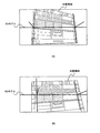
位置合わせ後の3Dモデルは、例えば、図14(B)や図16(B)に示すように、対象物体に合致した状態で表示部109に表示される。そのため、ユーザは、表示部109に表示された3Dモデルと対象物体との位置関係により、対象物体が変化したことを確認するなどして、設備の点検や管理を行うことが可能となる。或いは、情報処理装置100では、位置合わせ後において、表示部109に3次元のナビゲーション画像を表示させたり、ゲームの3次元のキャラクタを表示させたりすることが可能となる。
The 3D model after the positioning is displayed on the
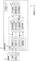
図1に示すように、情報処理装置100は、撮像部101、慣性センサ102、記憶部103、自己位置推定部104、重力方向推定部105、初期化処理部106、モデル位置推定部107、モデル描画部108、表示部109、認識開始判定部110、及び物体位置認識部111を備える。
As shown in FIG. 1, the
撮像部101は、対象物体を含む画像を撮像し、撮像した画像を入力画像とし、入力画像の画像データを出力する。撮像部101は、画像データを記憶部103に記憶する。画像データは、例えば、RGB(Red Green Blue)の各プレーンを持つRGB画像データである。
The
慣性センサ102は、情報処理装置100の加速度を測定し、測定した加速度を加速度データとして出力する。慣性センサ102は、加速度データを記憶部103に記憶する。慣性センサ102は、例えば、加速度センサやジャイロセンサなどであってもよい。
記憶部103は、例えば、メモリであって、RGB画像データ、加速度データ、さらに、3Dモデルデータと各種設定値を記憶する。3Dモデルデータは、例えば、世界座標系における3Dモデルの位置を表す位置情報とその位置におけるRGBデータとが含まれる。また、各種設定値は、例えば、仮想カメラ座標系における3Dモデルの任意の2点P1,m,P2,mなどが含まれる。なお、世界座標系や仮想カメラ座標系などの座標系については後述する。
The
自己位置推定部104は、記憶部103から読み出したRGB画像データに基づいて、世界座標系における実カメラ(例えば、撮像部101)の位置と姿勢を推定する。例えば、自己位置推定部104は、SLAM(Simultaneous Localization and Mapping)を用いて、複数画像フレームのRGB画像データから、実カメラの位置と姿勢を表すカメラパラメータを算出する。また、自己位置推定部104は、例えば、カメラパラメータを含む行列を算出する。カメラパラメータを含む行列は、例えば、世界座標系から実カメラ座標系への変換行列Tcwになり得る。詳細は動作例で説明する。自己位置推定部104は、変換行列Tcwなどをモデル描画部108とモデル位置推定部107へ出力する。
The self-
重力方向推定部105は、記憶部103から読み出した加速度データに基づいて、世界座標系における重力方向を推定する。例えば、重力方向推定部105は、内部メモリに記憶された式を利用して、加速度データから重力方向を推定する。詳細は動作例で説明する。重力方向推定部105は、推定した重力方向をモデル位置推定部107へ出力する。
The gravity
初期化処理部106は、記憶部103から読み出した3Dモデルデータと各種設定値とを利用して、仮想カメラ座標系を設定する。各種設定値としては、例えば、3Dモデル上の任意の2点P1,m,P2,mと、2点P1,m,P2,m間のユークリッド距離L、2点P1,m,P2,mとを含む平面の法線ベクトルnc、及び鉛直下方向ベクトルgmがある。そして、初期化処理部106は、仮想カメラ座標系における単位視線ベクトルr1,r2を算出する。初期化処理部106は、算出した単位視線ベクトルr1,r2と仮想カメラ座標系における各種数値とをモデル位置推定部107へ出力する。詳細は動作例で説明する。
The
モデル位置推定部107は、記憶部103から読み出した3Dモデルデータ、重力方向、単位視線ベクトルr1,r2、世界座標系から実カメラ座標系への変換行列Tcwなどを用いて、モデル座標系における3Dモデルの位置と姿勢を推定する。具体的には、例えば、モデル位置推定部107は、モデル座標系における3Dモデルの位置と姿勢を世界座標系における3Dモデルの位置と姿勢へそれぞれ変換する変換行列Twmを算出する。また、モデル位置推定部107は、例えば、世界座標系の3Dモデルの位置及び姿勢をカメラ座標系の3Dモデルの位置及び姿勢へ変換したり、モデル座標系における3Dモデルの位置及び姿勢へ変換したりする処理を行う。詳細は動作例で説明する。モデル位置推定部107は、カメラ座標系の3Dモデルの位置及び姿勢などをモデル描画部108へ出力し、モデル座標系における3Dモデルの位置及び姿勢と変換行列Twmなどを、物体位置認識部111へ出力する。
The model
なお、3Dモデルの位置及び姿勢の他の座標系への変換は、例えば、変換行列により行われる。他の座標系の位置及び姿勢へと変換するための数値が変換行列の各成分に含まれる。以下では、例えば、1つの変換行列により、ある座標系の3Dモデルの位置及び姿勢を、他の座標系の3Dモデルの位置及び姿勢へ変換することができるとして説明する。また、変換行列により、3Dモデルの位置及び姿勢がある座標系から他の座標系へ変換されるが、このことを、例えば、ある座標系における3Dモデルデータが、他の座標系における3Dモデルデータへ変換される、として説明する場合がある。3Dモデルの位置及び姿勢を、例えば、3Dモデルデータと称する場合がある。 The conversion of the position and orientation of the 3D model into another coordinate system is performed using, for example, a conversion matrix. Numerical values for conversion to a position and orientation in another coordinate system are included in each component of the conversion matrix. Hereinafter, for example, a description will be given on the assumption that the position and orientation of a 3D model in a certain coordinate system can be converted into the position and orientation of a 3D model in another coordinate system by using one transformation matrix. The transformation matrix converts the position and orientation of the 3D model from one coordinate system to another coordinate system. For example, this is because the 3D model data in one coordinate system is converted to the 3D model data in another coordinate system. May be described as being converted to The position and orientation of the 3D model may be referred to as, for example, 3D model data.
モデル描画部108は、入力画像に3Dモデルを描画する。具体的には、モデル描画部108は、以下の処理を行う。すなわち、モデル描画部108は、カメラ座標系の3Dモデルデータを、投影行列Tpを用いて、画像座標系の3Dモデルデータへ変換する。モデル描画部108は、RGB画像データと3Dモデルデータとを、画像座標系に描画する。この際、モデル描画部108は、画像座標系の3Dモデルの位置におけるRGB画像データを、3Dモデルの画像データへ変更する。モデル描画部108は、画像座標系におけるRGB画像データと3Dモデルの画像データとを表示部109と認識開始判定部110へ出力する。
The
表示部109は、モデル描画部108から出力されたRGB画像データと3Dモデルの画像データとに基づいて、入力画像と3Dモデルを表示する。表示部109に表示される3Dモデルの位置は、カメラ座標系における重力方向に応じて変化する。ユーザは、表示部109においてこのように変化する3Dモデルを見ながら、情報処理装置100(又は撮像部101)を移動させ、入力画像に含まれる対象物体と3Dモデルとを一致させて、「位置合わせ」を行う。そのように一致したときにおいて、表示部109に表示される対象物体と3Dモデルの例が、例えば、図14(B)や図16(B)となる。
The
図1に戻り、認識開始判定部110は、例えば、ユーザが情報処理装置100の操作ボタンを押圧したか否かにより、対象物体の位置合わせの開始判定を行う。認識開始判定部110は、ユーザにより、位置合わせの開始判定が行われたと判定したときは、その旨を物体位置認識部111へ通知する。
Returning to FIG. 1, the recognition
物体位置認識部111は、例えば、位置合わせの開始判定の行われた旨の通知を受け取ったとき、その通知を受け取ったときのモデル座標系から世界座標系への変換行列Twmを、モデル位置推定部107から受け取る。そして、物体位置認識部111は、この変換行列Twmを利用して、モデル画像系における3Dモデルデータを世界座標系の3Dモデルデータへ変換したり、世界座標系の3Dモデルデータをカメラ座標系の3Dモデルデータへ変換したりする。物体位置認識部111は、カメラ座標系の3Dモデルデータをモデル描画108へ出力する。モデル描画部108では、この3Dモデルデータに対して、投影行列Tpを用いて画像座標系への3Dモデルデータへ変換し、画像座標系に3Dモデルデータを描画する。表示部109では、描画結果に従って、入力画像と3Dモデルとを表示する。
The object
<各座標系について>
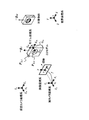
図2は各座標系の例を表す図である。本第1の実施の形態では、世界座標系(X,Y,Z)、仮想カメラ座標系(Xv,Yv,Zv)、実カメラ座標系(Xc,Yc,Zc)、モデル座標系(Xm,Ym,Zm)、及び画像座標系(x,y)の5つの座標系がある。
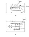
<About each coordinate system>
FIG. 2 is a diagram illustrating an example of each coordinate system. In the first embodiment, the world coordinate system (X, Y, Z), the virtual camera coordinate system ( Xv , Yv , Zv ), the real camera coordinate system ( Xc , Yc , Zc ), model coordinate system (X m, Y m, Z m) there are five coordinate system, and image coordinate system (x, y).
世界座標系(X,Y,Z)の任意の位置に世界座標系の原点Owが存在する。対象物体は、世界座標系(X,Y,Z)において、固定された位置に位置してもよい。また、3Dモデルも世界座標系(X,Y,Z)において、ある特定の位置に位置している。 World coordinate system (X, Y, Z) are present origin O w in the world coordinate system at an arbitrary position. The target object may be located at a fixed position in the world coordinate system (X, Y, Z). Further, the 3D model is also located at a specific position in the world coordinate system (X, Y, Z).
また、世界座標系における任意の位置に仮想カメラ座標系(Xv,Yv,Zv)の原点Ovが存在し、原点Ovを基準にして仮想カメラ座標系(Xv,Yv,Zv)がある。原点Ovは、例えば、仮想カメラの視点位置となる。 Further, the virtual camera coordinate system at an arbitrary position in the world coordinate system (X v, Y v, Z v) origin O v is present in the origin O v virtual camera coordinate system with respect to the (X v, Y v, Z v ). The origin Ov is, for example, the viewpoint position of the virtual camera.
実カメラ座標系(Xc,Yc,Zc)についても、世界座標系の任意の位置にその原点Ocが存在し、原点Ocを中心に実カメラ座標系(Xc,Yc,Zc)がある。原点Ocは、例えば、実カメラの視点位置となる。以下では、原点Ov,Ocを、仮想カメラと実カメラの視点位置とそれぞれ称する場合がある。 Actual camera coordinate system (X c, Y c, Z c) for also, the origin O c is present at any position in the world coordinate system, the actual camera coordinate system around the origin O c (X c, Y c , Z c ). The origin Oc is, for example, the viewpoint position of the real camera. Hereinafter, the origin O v, the O c, may be referred to each and viewpoint position of the virtual camera and the real cameras.
なお、仮想カメラ座標系(Xv,Yv,Zv)における3Dモデルの位置及び姿勢と、実カメラ座標系(Xc,Yc,Zc)における3Dモデルの位置及び姿勢は、視点位置がそれぞれ異なるため、異なるものとなる。また、実カメラ座標系(Xc,Yc,Zc)の視点位置Ocは、世界座標系(X,Y,Z)において移動可能である。 The position and orientation of the 3D model in the virtual camera coordinate system ( Xv , Yv , Zv ) and the position and orientation of the 3D model in the real camera coordinate system ( Xc , Yc , Zc ) are the viewpoint positions. Are different and therefore different. Moreover, the actual camera coordinate system (X c, Y c, Z c) the viewpoint position O c of is movable in the world coordinate system (X, Y, Z).
実カメラ座標系(Xc,Yc,Zc)の原点Ocと、3Dモデルの中心とを結ぶ線分上に、画像座標系(x,y)の原点oが存在する。画像座標系(x,y)は、世界座標系(X,Y,Z)において、実カメラ座標系(Xc,Yc,Zc)と3Dモデルとの間に位置する。実カメラの視点位置Ocと、画像座標系(x,y)の原点oとの間の距離は、例えば、焦点距離fと呼ばれ、世界座標系において一定の距離を維持する。 Actual camera coordinate system (X c, Y c, Z c) and the origin O c of, on a line connecting the center of the 3D model, the origin o of the image coordinate system (x, y) is present. The image coordinate system (x, y) is located between the real camera coordinate system ( Xc , Yc , Zc ) and the 3D model in the world coordinate system (X, Y, Z). A viewpoint position O c of the real camera, the distance between the origin o of the image coordinate system (x, y), for example, it called the focal length f, to maintain a constant distance in the world coordinate system.
さらに、3Dモデル上のある特定の位置(図2の例では、図面上、右上の角)を原点Omとするモデル座標系(Xm,Ym,Zm)がある。 Further, there is a model coordinate system (X m , Y m , Z m ) having an origin O m at a specific position on the 3D model (in the example of FIG. 2, the upper right corner in the drawing).
図2に示すように、対象物体には、世界座標系(X,Y,Z)における重力ベクトルgwが働く。図2では、Y軸方向の負方向に重力ベクトルgwが働くため、−gwとして表記している。重力ベクトルgwは、3Dモデルにも働く。 As shown in FIG. 2, the target object, the world coordinate system (X, Y, Z) is the gravity vector g w in work. In FIG. 2, since the gravity vector g w acts in the negative direction in the Y-axis direction, it is represented as −g w . The gravity vector g w also works for the 3D model.
本第1の実施の形態では、実カメラ座標系(Xc,Yc,Zc)において、重力ベクトルgcが存在する。 In the first embodiment, the actual camera coordinate system (X c, Y c, Z c) in, there is a gravity vector g c.
図3は、実カメラの視点位置Ocと、実カメラ座標系(Xc,Yc,Zc)における重力ベクトルgcとの関係例を表す図である。図3に示すように、視点位置Ocを、3Dモデルを見上げる方向に移動させると、重力ベクトル(−gc)は、視点位置Ocの方向へ傾く。一方、図2において、視点位置Ocを、3Dモデルに近づく方向へ移動させても、重力ベクトル(−gc)の方向はほとんど変わらない。 Figure 3 is a diagram representing the viewpoint position O c of the real camera, real camera coordinate system (X c, Y c, Z c) an example of the relationship between the gravity vector g c in. As shown in FIG. 3, the viewpoint position O c, is moved in a direction to look up a 3D model, the gravity vector (-g c) are inclined in the direction of the viewpoint position O c. On the other hand, in FIG. 2, the viewpoint position O c, be moved in a direction closer to a 3D model, the direction of the gravity vector (-g c) hardly changes.
すなわち、実カメラ座標系(Xc,Yc,Zc)における重力ベクトルgcは、例えば、重力ベクトルgwの方向(重力方向)に対して同じ向きを維持したまま、実カメラの視点位置Ocが世界座標系(X,Y,Z)を移動しても、その方向は変わらない。一方、重力ベクトルgwの方向(重力方向)に対して、実カメラの視点位置Ocがその向きを変える方向に移動すると、重力ベクトルgcの方向は変化する。このように、重力ベクトルgcの方向は、実カメラの視点位置Ocの移動により、変化する場合がある、という特徴を持つ。本第1の実施の形態では、このような視点位置Ocの移動により、重力ベクトルgcのその方向が変化する場合、その変化に応じて、3Dモデルの実カメラ座標系の位置及び姿勢を変化させるようにしている。詳細は動作例で説明する。 That is, the gravity vector g c in the real camera coordinate system (X c , Y c , Z c ) is, for example, the viewpoint position of the real camera while maintaining the same direction with respect to the direction of the gravity vector g w (gravity direction). When Oc moves in the world coordinate system (X, Y, Z), its direction does not change. On the other hand, when the viewpoint position O c of the real camera moves in the direction of changing its direction with respect to the direction of the gravity vector g w (the direction of gravity), the direction of the gravity vector g c changes. Thus, the direction of the gravity vector g c is the movement of the viewpoint position O c of the real camera, it may vary, with the feature that. In the first embodiment, by the movement of such a viewpoint position O c, if the direction of the gravity vector g c varies, depending on the change, the position and orientation of the real camera coordinate system of the 3D model I try to change it. Details will be described in an operation example.
なお、以下では、実カメラ座標系のことを、例えば、カメラ座標系と称する場合がある。 In the following, the actual camera coordinate system may be referred to as a camera coordinate system, for example.
<動作例>
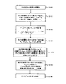
図4は情報処理装置100の動作例を表すフローチャートである。
<Operation example>
FIG. 4 is a flowchart illustrating an operation example of the
情報処理装置100は、処理を開始すると(S10)、初期化処理を行う(S11)。
When the processing is started (S10), the
図5は初期化処理の動作例を表すフローチャートである。初期化処理は、例えば、初期化処理部106で処理が行われ、仮想カメラ座標系における単位視線ベクトルr1,r2が算出される。
FIG. 5 is a flowchart illustrating an operation example of the initialization processing. The initialization processing is performed by, for example, the
初期化処理部106は、初期化処理を開始すると(S110)、仮想カメラ座標系における3Dモデルの任意の2点P1,v,P2,v(P1,v≠P2,v)を決定する(S111)。
When the
図6は、世界座標系(X,Y,Z)と仮想カメラ座標系(Xv,Yv,Zv)との関係例を表す図である。図6に示すように、任意の2点P1,v,P2,vは、仮想カメラ座標系(Xv,Yv,Zv)における3Dモデル上の任意の2点を表している。例えば、初期化処理部106は、記憶部103に記憶された、2点P1,v,P2,vの位置座標を、記憶部103から読み出すことで、任意の2点P1,v,P2,vを決定してもよい。
FIG. 6 is a diagram illustrating a relationship example between the world coordinate system (X, Y, Z) and the virtual camera coordinate system ( Xv , Yv , Zv ). As shown in FIG. 6, arbitrary two points P1 , v , P2 , v represent arbitrary two points on the 3D model in the virtual camera coordinate system ( Xv , Yv , Zv ). For example, the
図5に戻り、また、初期化処理部106は、2点P1,v,P2,v間のユークリッド距離Lを決定する(S111)。例えば、初期化処理部106は、2点P1,v,P2,vの位置座標に基づいて、その距離を計算することで、Lを計算してもよいし、記憶部103に記憶されたLを読み出すことで決定してもよい。
Returning to FIG. 5, the
さらに、初期化処理部106は、2点P1,v,P2,vを含む適当な平面の法線ベクトルnvを決定する(S111)。図6に示すように、法線ベクトルnvは、3Dモデルのある面に対する法線ベクトルでもよい。例えば、初期化処理部106は、点P1,v,P2,vの位置座標に基づいて、法線ベクトルnvを計算してもよいし、記憶部103から法線ベクトルnvの情報を読み出すことで、法線ベクトルnvを決定してもよい。
Furthermore, the
図5に戻り、さらに、初期化処理部106は、仮想カメラ座標系(Xv,Yv,Zv)における鉛直下向きベクトルgvを決定する(S111)。鉛直下向きベクトルgvは、例えば、図6に示すように、仮想カメラ座標系(Xv,Yv,Zv)における重力ベクトルとなり得る。例えば、初期化処理部106は、記憶部103から鉛直下向きベクトルgvの情報を読み出すことで、決定してもよい。この仮想カメラ座標系(Xv,Yv,Zv)における鉛直下向きベクトルgvも、重力ベクトルgcと同様に、例えば、図3に示すように、仮想カメラの視点位置Ovに応じて、変化する場合がある。
Returning to FIG. 5, further, the
図5に戻り、次に、初期化処理部106は、ある位置及び姿勢から2点P1,v,P2,vを観測する仮想カメラを定義する(S112)。例えば、初期化処理部106は、図6に示すように、世界座標系(X,Y,Z)の任意の位置Ovを、記憶部103から読み出して、仮想カメラの視点位置に設定することで、仮想カメラを定義する。
Returning to FIG. 5, then the
図5に戻り、次に、初期化処理部106は、仮想カメラ座標系(Xv,Yv,Zv)における単位視線ベクトルr1,r2(r1≠r2)を計算する(S113)。例えば、初期化処理部106は、仮想カメラの視点位置Ovの位置座標(0,0,0)と、仮想モデル座標系の2点P1,v,P2,vの位置座標とを結ぶ線分の長さが「1」となる2点の位置座標を計算し、その位置座標をそれぞれ単位視線ベクトルr1,r2の成分としてもよい。
Returning to FIG. 5, next, the
そして、初期化処理部106は、初期化処理を終了する(S114)。初期化処理部106は、計算した単位視線ベクトルr1,r2と、決定した法線ベクトルnv、及び鉛直下向きベクトルgvをモデル位置推定部107へ出力する。
Then, the
図4に戻り、次に、情報処理装置100は、RGB画像データと加速度データとを取得する(S12)。例えば、撮像部101は、撮像した入力画像のRGB画像データを記憶部103に記憶し、慣性センサ102は、入力画像を撮像したときに測定した加速度データを記憶部103に記憶する。
Returning to FIG. 4, next, the
なお、情報処理装置100は、S12からS17までの処理を、撮像部101で撮像した画像の画像フレーム毎に行う。従って、情報処理装置100は、画像フレーム毎に、RGB画像データを取得したり、画像フレーム毎に、慣性センサ102から加速度データを取得したりする。
Note that the
次に、情報処理装置100は、カメラの位置及び姿勢を推定する(S13)。例えば、自己位置推定部104は、SLAMを利用して、カメラパラメータを取得し、実カメラの位置及び姿勢を推定することで、取得したカメラパラメータを含む変換行列Tcwを計算する。
Next, the
ここで、SLAMについて説明する。SLAMとは、例えば、同一のカメラで撮像された複数の画像(2次元)に基づいて、画像の特徴点を抽出して追跡することで、カメラ周囲の3次元構造の認識と、カメラの位置及び姿勢の算出とを同時に行う技術である。 Here, SLAM will be described. SLAM is, for example, based on a plurality of images (two-dimensional) captured by the same camera, extracting and tracking feature points of the image, thereby recognizing a three-dimensional structure around the camera and recognizing the position of the camera. And the calculation of the posture at the same time.
SLAM処理として、自己位置推定部104では、例えば、以下の処理を行う。
As the SLAM processing, the self-
すなわち、最初に、自己位置推定部104は、記憶部103からRGB画像データを読み出し、RGB画像データにより示された複数の画像(又は画像フレーム)から、特徴点を抽出する。例えば、自己位置推定部104は、SIFT(Scale Invariant Feature Transform)やSURF(Speeded Up Robust Feature)などの公知の手法を用いて、各画像について、特徴点を抽出する。
That is, first, the self-
次に、自己位置推定部104は、各画像で抽出した特徴点の各画像におけるマッチングを行う。この際、自己位置推定部104は、特徴点抽出で用いた公知の手法で、マッチングを行ってもよい。
Next, the self-
そして、自己位置推定部104は、マッチング結果に基づいて、特徴点の3次元座標を算出し、算出した3次元座標から各画像に対応したカメラパラメータを算出する。カメラパラメータとしては、例えば、カメラの位置座標と座標軸の回転角を含む。自己位置推定部104は、このカメラパラメータを含む変換行列Tcwを算出する。この変換行列Tcwは、例えば、カメラの位置座標(又は位置)と座標軸の回転角(又は姿勢)を含むため、世界座標系(X,Y,Z)における任意の位置及び姿勢を、カメラの視点位置を原点としたカメラ座標系(Xc,Yc,Zc)における位置及び姿勢に変換する変換行列となり得る。
Then, the self-
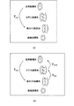
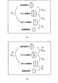
図7(A)は、各座標系の関係例を表す図である。自己位置推定部104は、SLAMを用いて、カメラの位置及び姿勢を算出することで、世界座標系(X,Y,Z)から実カメラ座標系(Xc,Yc,Zc)への変換行列Tcwを算出している。
FIG. 7A is a diagram illustrating a relationship example of each coordinate system. The self-
以上、SLAMの処理の例について説明した。SLAMには、例えば、EKF(Extended Kalman Filter)を用いたEKFベースのSLAMや、パーティクルフィルタを利用したSLAMなどがある。本第1の実施の形態では、例えば、どのような手法のSLAMを用いてもよい。 The example of the SLAM processing has been described above. Examples of the SLAM include an EKF-based SLAM using an EKF (Extended Kalman Filter) and a SLAM using a particle filter. In the first embodiment, for example, any method of SLAM may be used.
図4に戻り、次に、情報処理装置100は、重力方向を計算する(S14)。例えば、重力方向推定部105は、以下の処理を行う。
Returning to FIG. 4, next, the
すなわち、重力方向推定部105は、記憶部103から読み出した、カメラ座標系(Xc,Yc,Zc)の各軸方向の加速度データ(Ax,Ay,Az)から、以下の式を用いて、各軸方向に対する傾き(θ,ψ,φ)を計算する。
That is, the gravity
![]()
![]()
![]()
![]()
![]()
![]()
そして、重力方向推定部105は、傾き(θ,ψ,φ)に基づいて、重力方向を推定する。例えば、重力方向推定部105は、傾きが、(0,−1,0)のときは、カメラ座標系(Xc,Yc,Zc)の−Yc軸方向に重力方向があると推定し、傾きが、(1,0,0)のときは、カメラ座標系(Xc,Yc,Zc)のXc軸方向に重力方向があると推定する。重力方向推定部105は、推定した重力方向が、世界座標系(X,Y,Z)の重力方向であるとして、世界座標系(X,Y,Z)における重力ベクトルgwの方向(又は重力方向)を得る。
Then, the gravity
例えば、重力方向推定部105は、内部メモリに式(1)から式(3)を記憶し、本処理の際に読み出して、記憶部103から読み出した加速度データを式(1)から式(3)に代入することで、傾きを算出する。そして、重力方向推定部105は、その傾きに基づいて、重力ベクトルgwの方向を推定する。
For example, the gravity
以上が重力方向の計算方法である。 The above is the calculation method of the direction of gravity.
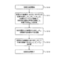
次に、情報処理装置100は、3Dモデルの位置と姿勢の計算処理(以下、「3Dモデルの計算処理」と称する場合がある。)を行う(S15)。
Next, the
図8は、3Dモデルの計算処理の動作例を表すフローチャートである。 FIG. 8 is a flowchart illustrating an operation example of the calculation processing of the 3D model.
モデル位置推定部107は、3Dモデルの計算処理を開始すると(S150)、カメラ座標系における重力ベクトルgcの方向と、仮想モデル座標系における鉛直下向きベクトルgvの方向とが一致するように法線nmを回転させる(S151)。
Model
図9(A)と図9(B)は、S151の処理を説明するための図である。本処理では、仮想カメラ座標系(Xv,Yv,Zv)における法線ベクトルnvを回転させて、カメラ座標系(Xc,Yc,Zc)における法線ベクトルncを算出する。その際に、モデル位置推定部107は、カメラ座標系(Xc,Yc,Zc)の重力ベクトルgcと、仮想カメラ座標系の鉛直下向きベクトルgvとを用いて計算する。モデル位置推定部107は、例えば、以下の計算を行う。
FIGS. 9A and 9B are diagrams for explaining the processing of S151. In this process, calculates the virtual camera coordinate system (X v, Y v, Z v) by rotating the normal vector n v in the camera coordinate system (X c, Y c, Z c) the normal vector n c in I do. At that time, the model
すなわち、モデル位置推定部107は、回転軸をv、回転軸vを中心にして法線ベクトルnvを法線ベクトルncへ回転させる回転角度をθとすると、
![]()
![]()
![]()
![]()
次に、モデル位置推定部107は、回転軸vのまわりに角度θだけ回転させる回転行列Rを、以下の式を用いて算出する。
Next, the model

そして、モデル位置推定部107は、回転行列Rを用いて、以下の式を利用して、カメラ座標系(Xc,Yc,Zc)における法線ベクトルncを計算する。
The model
![]()
![]()
なお、モデル位置推定部107は、例えば、カメラ位置推定処理(図4のS13)で得た変換行列Tcwと、重力方向計算処理(S14)で得た重力ベクトルgwを用いて、以下の式により、重力ベクトルgcを計算する。
Note that the model
![]()
![]()
例えば、モデル位置推定部107は、内部メモリに式(4)から式(8)を記憶し、本処理の際に内部メモリから式(4)から式(8)を読み出して、鉛直下向きベクトルgvや重力ベクトルgcなどを、式(4)から式(8)に代入するなどして、法線ベクトルncを計算する。
For example, the model
図8に戻り、次に、モデル位置推定部107は、固定視線のスケールt1,t2を計算する(S152)。
Returning to FIG. 8, next, the model
図10(A)は、スケールt1,t2の例を表す図である。スケールt1,t2は、例えば、カメラ座標系(Xc,Yc,Zc)の視点位置Ocから、初期化処理で得た単位視線ベクトルr1,r2を延長し、2点間の距離がLとなっている3Dモデル上の2点P1,c,P2,cへ延ばしたときの、単位視線ベクトルr1,r2に対するスケールを表す。 FIG. 10A is a diagram illustrating an example of the scales t 1 and t 2 . The scales t 1 and t 2 are obtained by extending the unit line-of-sight vectors r 1 and r 2 obtained by the initialization process from the viewpoint position O c in the camera coordinate system (X c , Y c , Z c ), for example, to obtain two points. It represents the scale for the unit line-of-sight vectors r 1 , r 2 when extending to two points P 1, c , P 2, c on the 3D model in which the distance between them is L.
モデル位置推定部107は、例えば、以下の式を利用して、スケールt1,t2を計算する。
The model
![]()
![]()
![]()
![]()
ただし、αは、以下の式となる。 Here, α is represented by the following equation.
![]()
![]()
例えば、モデル位置推定部107は、内部メモリに式(9)から式(11)を記憶し、処理の際に内部メモリから読み出して、S151で得た法線ベクトルncなどを式(9)から式(11)に代入することで、スケールt1,t2を得る。
For example, the model
図8に戻り、次に、モデル位置推定部107は、カメラ座標系における3Dモデルの2点P1,c,P2,cを、以下の式を用いて計算する(S153)。
Returning to FIG. 8, next, the model
P1,c=t1r1,P2,c=t2r2 ・・・(12)
例えば、モデル位置推定部107は、内部メモリに式(12)を記憶し、処理の際に内部メモリから読み出して、S152で計算したスケールt1,t2を式(12)に代入することで、2点P1,c,P2,cを得る。
P 1, c = t 1 r 1,
For example, the model
ここで、カメラ座標系(Xc,Yc,Zc)における任意の2点P1,c,P2,cと、カメラ座標系(Xc,Yc,Zc)における視点位置Ocとの関係について説明する。
Here, the camera coordinate system (X c, Y c, Z c) any two
図10(B)は、その関係例を表す図である。上述したように、カメラ座標系(Xc,Yc,Zc)における重力ベクトルgcは、カメラの視点位置Ocが重力ベクトルgwの方向(重力方向)に対して向きを変える場合、その方向が変化する。 FIG. 10B is a diagram illustrating an example of the relationship. As described above, the gravitational vector g c in the camera coordinate system (X c , Y c , Z c ) is obtained when the viewpoint position O c of the camera changes its direction with respect to the direction of the gravitational vector g w (gravity direction). The direction changes.
例えば、図10(B)に示すように、カメラの視点位置がOcからO’cへ移動した場合を考える。丁度、視点位置Ocが、3Dモデルに対して、世界座標系(X,Y,Z)のY軸方向へ(3Dモデルの上空方向へ)、移動した場合である。 For example, as shown in FIG. 10 (B), consider a case where the viewpoint position of the camera is moved from O c to O 'c. Just viewpoint position O c is, with respect to the 3D model, the world coordinate system (X, Y, Z) in the Y-axis direction (the sky direction of the 3D model), a case where the movement.
この場合、図3の場合と同様に、カメラ座標系(Xc,Yc,Zc)における重力ベクトルgcは、重力ベクトルgwの方向に対して向きを変えているため、その方向が変化する。従って、カメラの視点位置がOcにあるときの重力ベクトルgcと、カメラの視点位置がO’cにあるときの重力ベクトルgcとは異なるものとなる。この相違により、式(4)と式(5)に示すように、カメラの視点位置がOcにあるときの回転軸vと回転角度θと、カメラの視点位置がO’cにあるときの回転軸vと回転角度θとが異なるものとなる。カメラの視点位置の相違により、回転軸vと回転角度θとが異なると、式(6)に示す回転行列Rも異なるものとなり、結果として、法線ベクトルncも異なるものとなる。スケールt1,t2は、式(9)から式(11)に示すように、法線ベクトルncが含まれるため、上述したカメラの視点位置の相違により、スケールt1,t2も異なるものとなる。このスケールt1,t2の相違により、図10(B)に示すように、カメラの視点位置がOcからO’cへ移動すると、カメラ座標系(Xc,Yc,Zc)における2点P1,c,P2,cは、2点P’1,c,P’2,cへそれぞれ移動する。従って、例えば、視点位置O’cからは、視点位置Ocの場合と比較して、3Dモデルの上面が大きく見える状態となる。
In this case, as in the case of FIG. 3, the gravity vector g c in the camera coordinate system (X c , Y c , Z c ) changes its direction with respect to the direction of the gravity vector g w. Change. Therefore, different from the gravity vector g c when the gravity vector g c when the viewpoint position of the camera is O c, the viewpoint position of the camera is in the O 'c. This difference, as shown in equation (4) and (5), when the rotation axis v and the rotational angle θ of when the viewpoint position of the camera is O c, the viewpoint position of the camera is in the O 'c The rotation axis v and the rotation angle θ are different. The difference in the point of view of the camera position, when the rotation axis v and the rotational angle θ are different, also becomes different rotation matrix R shown in equation (6), as a result, also be different normal vector n c. Scale t 1, t 2, as shown from equation (9) into equation (11), because it contains the normal vector n c, the difference in the viewpoint position of the camera described above,
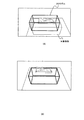
図11(A)と図11(B)は、カメラの視点位置をOcからO’cへ変えたときの、3Dモデルの表示例を表す図である。図11(B)は、図11(A)と比較して、3Dモデルの上面部分が大きく表示されているのがわかる。 Figure 11 (A) and FIG. 11 (B) when the viewpoint position of the camera is changed from O c to O 'c, is a diagram illustrating a display example of a 3D model. FIG. 11B shows that the top surface of the 3D model is displayed larger than in FIG. 11A.
このように、本第1の実施の形態では、カメラ座標系(Xc,Yc,Zc)における3Dモデルの位置と姿勢(例えば、例えば、2点P1,c,P2,c)を、カメラ座標系からの重力方向(例えば、重力ベクトルgc)に応じて変化させるようにしている。このような関係により、情報処理装置100は、図11(A)や図11(B)に示すように、3Dモデルの位置と姿勢がカメラの視点位置Ocの位置と姿勢に応じて変化する。
As described above, in the first embodiment, the position and the posture (for example, two points P 1, c , P 2, c ) of the 3D model in the camera coordinate system (X c , Y c , Z c ). Is changed in accordance with the direction of gravity from the camera coordinate system (for example, the gravity vector g c ). Such relationships, the
図8に戻り、次に、モデル位置推定部107は、カメラ座標系(Xc,Yc,Zc)の重力ベクトルgcと、法線ベクトルnc、及びモデル幅Wに基づいて、カメラ座標系(Xc,Yc,Zc)からモデル座標系(Xm,Ym,Zm)へ、座標系を変換する変換行列Tmcを計算する(S154)。変換行列Tmcの全体の座標系における位置付けは、例えば、図7(B)に示すものとなる。なお、モデル幅Wは、例えば、図12に示すように、カメラ座標系における点P1,cから、モデル座標系の原点Omまでの距離を表し、モデル座標系のXm軸方向における3Dモデルの長さを表す。
Referring back to FIG. 8, the model
例えば、モデル位置推定部107は、変換行列Tmcの全成分に、重力ベクトルgcと、法線ベクトルnc、及びモデル幅Wの全部又は一部を含む行列を計算してもよい。或いは、モデル位置推定部107は、例えば、変換行列Tmcの一部の成分が数値とし、他の成分に、重力ベクトルgcと、法線ベクトルnc、及びモデル幅Wの全部又は一部を含む行列を計算してもよい。或いは、モデル位置推定部107は、例えば、内部メモリに、変換行列Tmcを記憶しておき、重力ベクトルgcと、法線ベクトルnc、及びモデル幅Wを、変換行列Tmcの各成分の全部又は一部に代入することで、変換行列Tmcを得るようにしてもよい。
For example, the model
なお、モデル幅Wは、例えば、記憶部103やモデル位置推定部107の内部メモリに記憶しておき、モデル位置推定部107から記憶部103や内部メモリから読み出して、変換行列Tmcを計算するようにしてもよい。
Note that the model width W is stored in, for example, the internal memory of the
図8に戻り、次に、モデル位置推定部107は、世界座標系におけるカメラの位置と、3Dモデル上の2点P1,c,P2,cに基づいて、モデル座標系(Xm,Ym,Zm)から世界座標系(X,Y,Z)へ、座標系を変換する変換行列Twmを計算する(S155)。
Returning to FIG. 8, the model
図12は、カメラ座標系(Xc,Yc,Zc)とモデル座標系(Xm,Ym,Zm)の関係例を表す図である。本処理では、3Dモデル上の2点P1,c,P2,cを、カメラ座標系(Xc,Yc,Zc)の点から、モデル座標系(Xm,Ym,Zm)への点へ変換する変換行列Twmを計算する。丁度、カメラの視点位置Ocから、3Dモデルの視点位置Omへ、視点位置を変えたときに、3Dモデル上の2点を、モデル座標系の2点P1,m,P2,mへ変換する場合の変換行列Twmを計算している。
Figure 12 is a diagram showing the camera coordinate system (X c, Y c, Z c) a model coordinate system (X m, Y m, Z m) an example of the relationship. In this process, the two
図7(B)に示すように、S154の処理により、カメラ座標系(Xc,Yc,Zc)からモデル座標系(Xm,Ym,Zm)への変換行列Twmを計算した。また、自己位置推定処理(図4のS13)により、世界座標系(X,Y,Z)からカメラ座標系(Xc,Yc,Zc)への変換行列Tcwを計算した。本処理においては、この関係を利用して、モデル座標系(Xm,Ym,Zm)から世界座標系(X,Y,Z)への変換行列Twmを計算する。 As shown in FIG. 7 (B), the processing of S154, the camera coordinate system (X c, Y c, Z c) model coordinate system (X m, Y m, Z m) computing a transformation matrix T wm to did. Further, a transformation matrix T cw from the world coordinate system (X, Y, Z) to the camera coordinate system (X c , Y c , Z c ) was calculated by the self-position estimation processing (S13 in FIG. 4). In this process, by utilizing this relationship, the model coordinate system (X m, Y m, Z m) to compute the transformation matrix T wm from the world coordinate system (X, Y, Z) to.
すなわち、モデル位置推定部107は、以下の式を利用して、変換行列Twmを計算する。
That is, the model
![]()
![]()
例えば、モデル位置推定部107は、内部メモリから式(13)を読み出して、S13で計算した変換行列Tcwと、S154で計算した変換行列Tmcとを、式(13)に代入することで、変換行列Twmを得る。
For example, the model
図8に戻り、モデル位置推定部107は、S155の処理を終了すると、3Dモデルの計算処理を終了する(S156)。
Returning to FIG. 8, when the process of S155 ends, the model
以上、3Dモデル計算処理(図4のS15)について説明した。 The 3D model calculation processing (S15 in FIG. 4) has been described above.
なお、モデル位置推定部107は、自己位置推定部104から受け取った変換行列Tcwを用いて、記憶部103から読み出した世界座標系(X,Y,Z)における3Dモデルデータを、カメラ座標系(Xc,Yc,Zc)における3Dモデルデータへ変換する。モデル位置推定部107は、カメラ座標系(Xc,Yc,Zc)における3Dモデルデータを、モデル描画部108へ出力する。
The model
また、モデル位置推定部107は、S154において算出した変換行列Tmcを利用して、カメラ座標系(Xc,Yc,Zc)における3Dモデルデータを、モデル座標系(Xm,Ym,Zm)における3Dモデルデータへ変換する。モデル位置推定部107は、モデル座標系(Xm,Ym,Zm)における3Dモデルデータと、S155で算出した変換行列Twmとを、物体位置認識部111へ出力する。
Further, the model
図4に戻り、次に、情報処理装置100は、カメラ映像に3Dモデルを描画する(S16)。例えば、モデル描画部108は、以下の処理を行う。
Returning to FIG. 4, next, the
すなわち、モデル描画部108は、モデル位置推定部107から受け取った、カメラ座標系(Xc,Yc,Zc)における3Dモデルデータに対して、図13(A)に示すように、投影行列Tpを用いて、画像座標系(x,y)の3Dモデルデータへ変換する。そして、モデル描画部108は、記憶部103から読み出したRGBデータ(又はカメラ映像)と、変換後の3Dモデルデータとを、画像座標系(x,y)に描画する。この際、モデル描画部108は、画像座標系(x,y)における3Dモデルの位置における入力画像のRGB画像データを、3Dモデルの画像データに変更することで、3Dモデルを描画する。モデル描画部108は、描画結果を表示部109と認識開始判定部110へ出力する。表示部109は、描画結果に従って、カメラ映像に3Dモデルが写っている画像を表示する。
That is, as shown in FIG. 13A, the
例えば、図11(A)や図11(B)、及び図14(A)は、表示部109に表示されるカメラ映像と3Dモデルの例を表す。カメラ映像には対象物体(図11(A)の例は、ティッシュ箱)が含まれており、ユーザが、3Dモデルを対象物体に一致させるように、撮像部101(又は情報処理装置100)を移動させることで、「位置合わせ」が行われる。
For example, FIG. 11A, FIG. 11B, and FIG. 14A show examples of a camera image and a 3D model displayed on the
図4に戻り、次に、情報処理装置100は、ユーザの決定操作が行われたか否かを判定する(S17)。決定操作とは、例えば、ユーザが表示部109に写っている映像において、対象物体と3Dモデルとが一致したと判断したときに、情報処理装置100の操作ボタンなどを押す操作のことである。例えば、図14(B)は、表示部109に表示された3Dモデルの例であるが、3Dモデルと対象物体とが一致したとユーザが判断すると、所定の操作ボタンをユーザが押圧する。認識開始判定部110は、操作ボタンを押圧したことを示す信号を操作ボタンから受信したとき、決定操作が行われたと判定し(S17でYes)、その信号を受け取らかったとき、決定操作がおこなわれていないと判定する(S17でNo)。決定操作が行われなったとき、図4に示すように、情報処理装置100は、S12へ移行して、S12からS17までの処理を繰り返す。操作ボタンに代えて、例えば、表示部109に表示されたタッチパネルの操作により決定操作が行われてもよい。
Returning to FIG. 4, next, the
情報処理装置100は、決定操作が行われたと判定したとき(S17でYes)、対象物体の位置及び姿勢を計算する(S18)。具体的には、物体位置認識部111は、例えば、決定操作が行われたときにモデル位置推定部107から受け取った変換行列Twmを取得することで、「位置合わせ」を行うことになる。決定操作が行われたときの変換行列Twmは、例えば、世界座標系における対象物体の位置及び姿勢と、世界座標系における3Dモデルの位置及び姿勢とが、ある対応関係にあるとき(又はマッピングしたとき)である。対応関係としては、例えば、世界座標系において、対象物体と3Dモデルとが一致する関係がある。物体位置認識部111は、このような対応関係にあるときの、変換行列Twmを、モデル位置推定部107から取得している、といえる。
When determining that the determination operation has been performed (Yes in S17), the
そして、物体位置認識部111は、図13(B)に示すように、「位置合わせ」により取得した変換行列Twmや、モデル位置推定部107から受け取った変換行列Tcw、及び投影行列Tpを用いて、座標変換を(1)から(3)の順で行う。
Then, as shown in FIG. 13B, the object
具体的には、情報処理装置100は、例えば、以下の処理を行う。すなわち、物体位置認識部111は、モデル位置推定部107から受け取った、モデル座標系(Xm,Ym,Zm)における3Dモデルデータを、決定操作のタイミングでモデル位置推定部107から受け取った変換行列Twmを用いて、世界座標系(X,Y,Z)の3Dモデルデータへ変換する(図13(B)の(1))。さらに、物体位置認識部111は、自己位置推定部104から受け取った変換行列Tcwを用いて、世界座標系(X,Y,Z)の3Dモデルデータを、カメラ座標系(Xc,Yc,Zc)の3Dモデルデータへ変換する(図13(B)の(2))。物体位置認識部111は、カメラ座標系(Xc,Yc,Zc)における3Dモデルデータをモデル描画部108へ出力する。モデル描画部108では、投影行列Tpを用いて、物体位置認識部111から受け取った、カメラ座標系(Xc,Yc,Zc)における3Dモデルデータを、画像座標系(x,y)の3Dモデルデータへ変換する(図13(B)の(3))。そして、モデル描画部108は、変換後の3Dモデルデータと、記憶部103から読み出したRGB画像データとを、画像座標系(x,y)に描画する。
Specifically, the
なお、モデル描画部108は、投影行列Tpを用いることで、x=−fXc/Zc、y=−fYc/Zcにより、カメラ座標系の点(Xc,Yc,Zc)を、画像座標系の点(x,y)へ変換する。モデル描画部108は、例えば、内部メモリに投影行列Tpを記憶しておき、処理の際に読み出して、カメラ座標系(Xc,Yc,Zc)における3Dモデルデータに適用することで、画像座標系(x,y)における3Dモデルデータを得る。
Incidentally, the
図13(B)に示すように、座標変換が(1)から(3)の順で行われ、物体位置認識部111では、世界座標系(X,Y,Z)における3Dモデルデータを生成した。その後の座標変換により、情報処理装置100では、この3Dモデルデータを、世界座標系(X,Y,Z)からカメラ座標系(Xc,Yc,Zc)を介して、画像座標系(x,y)へと変換した。このように、「位置合わせ」後、3Dモデルデータは、世界座標系(X,Y,Z)を介して3Dモデルデータを画像座標系(x,y)へと変換されている。そのため、3Dモデルデータは、「位置合わせ」後、世界座標系(X,Y,Z)と対応して表示部109に表示される。例えば、図14(B)において「位置合わせ」が行われた後は、対象物体である「ティッシュ箱」と、3Dモデルデータとが一致した状態で、表示部109に表示される。カメラの位置及び姿勢を変化させても、3Dモデルは対象物体と一致した状態で表示される。
As shown in FIG. 13B, coordinate conversion is performed in the order of (1) to (3), and the object
図15(A)から図16(B)は、異なる形状の3Dモデルの例を表す。また、対象物体も、「サーバ装置」の例を表している。図15(A)から図16(B)に示すように、3Dモデルは、重力ベクトルgcに応じて、その位置と姿勢が変化している。 FIGS. 15A to 16B show examples of 3D models having different shapes. The target object also represents an example of the “server device”. As shown in FIG. 16 (B) from FIG. 15 (A), 3D model, depending on the gravity vector g c, is changing its position and orientation.
このように、本第1の実施の形態における3Dモデルは、重力ベクトルgcに応じて、その位置と姿勢が変化する。そのため、3Dモデルが表示部109において固定となっている場合と比較して、ユーザがカメラを移動させる自由度が増し、カメラの位置と姿勢に応じて、「位置合わせ」を容易に行うことができる。
Thus, 3D model in the first embodiment, depending on the gravity vector g c, the position and orientation changes. Therefore, compared to the case where the 3D model is fixed on the
また、本情報処理装置100における「位置合わせ」に際して、3Dモデルの画像データの特徴点を検出したり、対象物体の特徴点を検出したりする処理は、S14からS18までの処理では行われない。従って、図11(A)などに示す「ティッシュ箱」や、図15(A)などに示す「サーバ装置」など、「見た目の特徴が乏しい」対象物体の画像であっても、重力ベクトルgcに応じて変化する3Dモデルを用いているため、精度の良い「位置合わせ」を行うことが可能となる。
In addition, in the “positioning” in the
[その他の実施の形態]
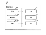
図17は、情報処理装置100のハードウェア構成例を表す図である。
[Other embodiments]
FIG. 17 is a diagram illustrating a hardware configuration example of the
情報処理装置100は、さらに、カメラ120、メモリ121、CPU(Central Processing Unit)122、ROM(Read Only Memory)123、及びRAM(Random Access Memory)124を備える。
The
メモリ121は、例えば、第1の実施の形態における記憶部103に対応する。
The
また、CPU122は、ROM123に記憶されたプログラムを読み出してRAM124にロードし、ロードしたプログラムを実行する。これにより、CPU122は、自己位置推定部104、重力方向推定部105、初期化処理部106、モデル位置推定部107、モデル描画部108、表示部109、認識開始判定部110、及び物体位置認識部111の機能を実現する。CPU122は、例えば、自己位置推定部104、重力方向推定部105、初期化処理部106、モデル位置推定部107、モデル描画部108、表示部109、認識開始判定部110、及び物体位置認識部111に対応する。
Further, the
なお、CPU122に代えて、MPU(Micro Processing Unit)やDSP(Digital Signal Processor)、FPGA(Field Programmable Gate Array)などのプロセッサやコントローラなどが用いられてもよい。
Note that, instead of the
図18は、情報処理装置100の他の構成例を表す図である。図18に示す例は、情報処理装置100の外部に撮像装置130があり、撮像装置130において、対象物体を含む画像を撮像する例を示す。撮像装置130は、例えば、カメラなどであり、撮像部101と慣性センサ102を含む。撮像装置130は、移動可能であり、ユーザにより様々な場所に移動することができる。撮像装置130で撮像されたRGBデータや、計測された加速度データは、有線や無線で情報処理装置100へ送信することができる。図18に示すように、情報処理システム10には、情報処理装置100と撮像装置130が含まれる。
FIG. 18 is a diagram illustrating another configuration example of the
以上まとめると、付記のようになる。 The summary is as follows.
(付記1)
情報処理装置の加速度データを出力する慣性センサと、
前記加速度データから世界座標系における第1の重力方向を推定する重力方向推定部と、
カメラ座標系におけるモデルの位置と姿勢を、カメラ座標系に対する前記第1の重力方向に応じて変化させ、カメラ座標系における前記モデルの位置と姿勢をモデル座標系における前記モデルの位置と姿勢へそれぞれ変換し、モデル座標系における前記モデルの位置と姿勢を世界座標系における前記モデルの位置と姿勢へそれぞれ変換する第1の変換行列を算出するモデル位置推定部と、
カメラ座標系における前記モデルの位置と姿勢を画像座標系における前記モデルの位置に変換し、入力画像と前記モデルとを画像座標系に描画するモデル描画部と、
前記モデル描画部の描画結果に従って、前記入力画像と前記モデルとを表示する表示部と
を備えることを特徴とする情報処理装置。
(Appendix 1)
An inertial sensor that outputs acceleration data of the information processing device;
A gravitational direction estimating unit that estimates a first gravitational direction in a world coordinate system from the acceleration data;
The position and orientation of the model in the camera coordinate system are changed according to the first direction of gravity with respect to the camera coordinate system, and the position and orientation of the model in the camera coordinate system are respectively changed to the position and orientation of the model in the model coordinate system. A model position estimating unit that calculates a first conversion matrix that converts and converts the position and orientation of the model in the model coordinate system to the position and orientation of the model in the world coordinate system, respectively.
A model drawing unit that converts a position and orientation of the model in a camera coordinate system into a position of the model in an image coordinate system, and draws an input image and the model in an image coordinate system.
An information processing apparatus, comprising: a display unit that displays the input image and the model according to a drawing result of the model drawing unit.
(付記2)
更に、前記モデルと前記入力画像に含まれる対象物体とが世界座標系で対応関係にあるときの前記第1の変換行列を前記モデル位置推定部から取得する物体位置認識部を備えることを特徴とする付記1記載の情報処理装置。
(Appendix 2)
Further, an object position recognizing unit that acquires the first transformation matrix from the model position estimating unit when the model and the target object included in the input image are in a correspondence relationship in a world coordinate system, The information processing apparatus according to
(付記3)
前記物体位置認識部は、前記モデルと前記対象物体とが世界座標系で一致したときの前記第1の変換行列を前記モデル位置推定部から取得することを特徴とする付記2記載の情報処理装置。
(Appendix 3)
The information processing apparatus according to
(付記4)
前記物体位置認識部は、ユーザの決定操作を示す信号を受信したとき、前記第1の変換行列を前記モデル位置推定部から取得することを特徴とする付記2記載の情報処理装置。
(Appendix 4)
The information processing apparatus according to
(付記5)
前記物体位置認識部は、前記第1の変換行列を利用して、モデル座標系における前記モデルの位置と姿勢を、世界座標系を介してカメラ座標系における前記モデルの位置と姿勢へそれぞれ変換し、
前記モデル描画部は、前記物体位置認識部でカメラ座標系に変換された前記モデルの位置と姿勢に基づいて、前記モデルと入力画像を画像座標系に描画する
ことを特徴とする付記2記載の情報処理装置。
(Appendix 5)
The object position recognition unit converts the position and orientation of the model in a model coordinate system into the position and orientation of the model in a camera coordinate system via a world coordinate system, using the first transformation matrix. ,
3. The model drawing unit according to
(付記6)
前記モデル位置推定部は、前記第1の重力方向を、カメラ座標系における第2の重力方向に変換して、カメラ座標系に対する前記第1の重力方向とし、
カメラ座標系における視点位置が前記第1の重力方向が変化する方向へ移動するとき、前記第2の重力方向は変化し、カメラ座標系における視点位置が前記第1の重力方向が変化しない方向に移動するとき、前記第2の重力方向は変化しないことを特徴とする付記1記載の情報処理装置。
(Appendix 6)
The model position estimating unit converts the first gravitational direction into a second gravitational direction in a camera coordinate system, and sets the first gravitational direction as the first gravitational direction in a camera coordinate system.
When the viewpoint position in the camera coordinate system moves in a direction in which the first gravity direction changes, the second gravity direction changes, and the viewpoint position in the camera coordinate system moves in a direction in which the first gravity direction does not change. The information processing apparatus according to
(付記7)
更に、前記入力画像の画像データに基づいて、世界座標系における撮像部又は撮像装置の位置と姿勢を推定し、推定した位置と姿勢に基づいて、世界座標系からカメラ座標系へ変換する第2の変換行列を算出する自己位置推定部を備え、
前記モデル位置推定部は、前記第2の変換行列を用いて、前記第1の重力方向を前記第2の重力方向へ変換することを特徴とする付記6記載の情報処理装置。
(Appendix 7)
Further, based on the image data of the input image, the position and orientation of the imaging unit or the imaging device in the world coordinate system are estimated, and based on the estimated position and orientation, a second coordinate conversion is performed from the world coordinate system to the camera coordinate system. A self-position estimating unit that calculates a transformation matrix of
The information processing apparatus according to claim 6, wherein the model position estimating unit converts the first gravitational direction into the second gravitational direction using the second conversion matrix.
(付記8)
更に、前記モデル上の任意の2点と、前記2点間のユークリッド距離、前記2点を含む平面における第1の法線ベクトル、及び鉛直下方向ベクトルに基づいて、仮想モデル座標系を設定し、仮想モデル座標系における仮想カメラの視点位置から前記2点への単位視線ベクトルを算出する初期化処理部を備えることを特徴とする付記1記載の情報処理装置。
(Appendix 8)
Further, a virtual model coordinate system is set based on any two points on the model, a Euclidean distance between the two points, a first normal vector on a plane including the two points, and a vertical downward vector. The information processing apparatus according to
(付記9)
更に、前記入力画像の画像データに基づいて、世界座標系における撮像部又は撮像装置の位置と姿勢を推定し、世界座標系からカメラ座標系へ変換する第2の変換行列を算出する自己位置推定部を備え、
前記モデル位置設定部は、前記第2の変換行列を用いて、前記第1の重力方向を前記第2の重力方向へ変換し、前記第2の重力方向と前記単位視線ベクトルとに基づいて、カメラ座標系における前記モデルの位置と姿勢をモデル座標系における前記モデルの位置と姿勢へそれぞれ変換する第3の変換行列を算出し、前記第3の変換行列を用いて、カメラ座標系における前記モデルの位置と姿勢をモデル座標系における前記モデルの位置と姿勢へそれぞれ変換することを特徴とする付記8記載の情報処理装置。
(Appendix 9)
Further, self-position estimation for estimating the position and orientation of the imaging unit or the imaging device in the world coordinate system based on the image data of the input image and calculating a second transformation matrix for converting the world coordinate system to the camera coordinate system. Part,
The model position setting unit converts the first gravitational direction to the second gravitational direction using the second conversion matrix, and based on the second gravitational direction and the unit line-of-sight vector, Calculating a third transformation matrix for transforming the position and orientation of the model in the camera coordinate system into the position and orientation of the model in the model coordinate system, and using the third transformation matrix to calculate the model in the camera coordinate system; 9. The information processing apparatus according to claim 8, wherein the position and the posture of the model are respectively converted into the position and the posture of the model in a model coordinate system.
(付記10)
前記モデル位置推定部は、前記第1の重力方向を有する重力ベクトルと前記鉛直下方向ベクトルとに基づいて、前記第1の法線ベクトルを、カメラ座標系における第2の法線ベクトルへ変換し、前記第2の法線ベクトルと前記単位視線ベクトルとに基づいて、カメラ座標系における前記モデルの2点を算出し、カメラ座標系における前記モデルの2点と、前記第2の法線ベクトル、及びモデル座標系のX軸方向における前記モデルの長さとに基づいて、前記第3の変換行列を算出することを特徴とする付記9記載の情報処理装置。
(Appendix 10)
The model position estimating unit converts the first normal vector into a second normal vector in a camera coordinate system based on the gravity vector having the first gravity direction and the vertical downward vector. Calculating two points of the model in a camera coordinate system based on the second normal vector and the unit line-of-sight vector, and calculating the two points of the model in a camera coordinate system, and the second normal vector; 10. The information processing apparatus according to claim 9, wherein the third transformation matrix is calculated based on a length of the model in the X-axis direction of the model coordinate system.
(付記11)
前記モデル位置推定部は、前記第2の変換行列をTcw、前記第3の変換行列をTmcとすると、内部メモリから読み出した以下の式(14)を用いて、前記第1の変換行列Twmを算出することを特徴とする付記10記載の情報処理装置。
![]()
Assuming that the second transformation matrix is T cw and the third transformation matrix is T mc , the model position estimating unit calculates the first transformation matrix by using the following equation (14) read from the internal memory. The information processing device according to claim 10, wherein Twm is calculated.
![]()
(付記12)
情報処理装置の加速度データを出力し、
前記加速度データから世界座標系における第1の重力方向を推定し、
カメラ座標系におけるモデルの位置と姿勢を、カメラ座標系に対する前記第1の重力方向に応じて変化させ、カメラ座標系における前記モデルの位置と姿勢をモデル座標系における前記モデルの位置と姿勢へそれぞれ変換し、モデル座標系における前記モデルの位置と姿勢を世界座標系における前記モデルの位置と姿勢へそれぞれ変換する第1の変換行列を算出し、
カメラ座標系における前記モデルの位置と姿勢を画像座標系における前記モデルの位置に変換し、入力画像と前記モデルとを画像座標系に描画し、
描画結果に従って、前記入力画像と前記モデルとを表示する
ことを特徴とする位置合わせ方法。
(Appendix 12)
Outputting acceleration data of the information processing device,
Estimating a first direction of gravity in the world coordinate system from the acceleration data,
The position and orientation of the model in the camera coordinate system are changed according to the first direction of gravity with respect to the camera coordinate system, and the position and orientation of the model in the camera coordinate system are respectively changed to the position and orientation of the model in the model coordinate system. Calculating a first transformation matrix for transforming the position and orientation of the model in the model coordinate system to the position and orientation of the model in the world coordinate system, respectively.
Convert the position and orientation of the model in the camera coordinate system to the position of the model in the image coordinate system, draw the input image and the model in the image coordinate system,
A positioning method, comprising: displaying the input image and the model according to a drawing result.
(付記13)
情報処理装置のコンピュータに実行させるプログラムであって、
前記情報処理装置の加速度データを出力し、
前記加速度データから世界座標系における第1の重力方向を推定し、
カメラ座標系におけるモデルの位置と姿勢を、カメラ座標系に対する前記第1の重力方向に応じて変化させ、カメラ座標系における前記モデルの位置と姿勢をモデル座標系における前記モデルの位置と姿勢へそれぞれ変換し、モデル座標系における前記モデルの位置と姿勢を世界座標系における前記モデルの位置と姿勢へそれぞれ変換する第1の変換行列を算出し、
カメラ座標系における前記モデルの位置と姿勢を画像座標系における前記モデルの位置に変換し、入力画像と前記モデルとを画像座標系に描画し、
描画結果に従って、前記入力画像と前記モデルとを表示する
処理を前記コンピュータに実行させるプログラム。
(Appendix 13)
A program to be executed by a computer of the information processing apparatus,
Outputting acceleration data of the information processing device;
Estimating a first direction of gravity in the world coordinate system from the acceleration data,
The position and orientation of the model in the camera coordinate system are changed according to the first direction of gravity with respect to the camera coordinate system, and the position and orientation of the model in the camera coordinate system are respectively changed to the position and orientation of the model in the model coordinate system. Calculating a first transformation matrix for transforming the position and orientation of the model in the model coordinate system to the position and orientation of the model in the world coordinate system, respectively.
Convert the position and orientation of the model in the camera coordinate system to the position of the model in the image coordinate system, draw the input image and the model in the image coordinate system,
A program for causing the computer to execute a process of displaying the input image and the model according to a drawing result.
10:情報処理システム 100:情報処理装置
101:撮像部 102:慣性センサ
103:記憶部 104:自己位置推定部
105:重力方向推定部 106:初期化処理部
107:モデル位置推定部 108:モデル描画部
109:表示部 110:認識開始判定部
111:物体位置認識部 120:カメラ
122:CPU 130:撮像装置
10: Information processing system 100: Information processing apparatus 101: Imaging unit 102: Inertial sensor 103: Storage unit 104: Self-position estimation unit 105: Gravity direction estimation unit 106: Initialization processing unit 107: Model position estimation unit 108: Model drawing Unit 109: display unit 110: recognition start determination unit 111: object position recognition unit 120: camera 122: CPU 130: imaging device
Claims (6)
前記加速度データから世界座標系における第1の重力方向を推定する重力方向推定部と、
カメラ座標系におけるモデルの位置と姿勢を、カメラ座標系に対する前記第1の重力方向に応じて変化させ、カメラ座標系における前記モデルの位置と姿勢をモデル座標系における前記モデルの位置と姿勢へそれぞれ変換し、モデル座標系における前記モデルの位置と姿勢を世界座標系における前記モデルの位置と姿勢へそれぞれ変換する第1の変換行列を算出するモデル位置推定部と、
カメラ座標系における前記モデルの位置と姿勢を画像座標系における前記モデルの位置に変換し、入力画像と前記モデルとを画像座標系に描画するモデル描画部と、
前記モデル描画部の描画結果に従って、前記入力画像と前記モデルとを表示する表示部と
を備えることを特徴とする情報処理装置。 An inertial sensor that outputs acceleration data of the information processing device;
A gravitational direction estimating unit that estimates a first gravitational direction in a world coordinate system from the acceleration data;
The position and orientation of the model in the camera coordinate system are changed according to the first direction of gravity with respect to the camera coordinate system, and the position and orientation of the model in the camera coordinate system are respectively changed to the position and orientation of the model in the model coordinate system. A model position estimating unit that calculates a first conversion matrix that converts and converts the position and orientation of the model in the model coordinate system to the position and orientation of the model in the world coordinate system, respectively.
A model drawing unit that converts a position and orientation of the model in a camera coordinate system into a position of the model in an image coordinate system, and draws an input image and the model in an image coordinate system.
An information processing apparatus, comprising: a display unit that displays the input image and the model according to a drawing result of the model drawing unit.
カメラ座標系における視点位置が前記第1の重力方向が変化する方向へ移動するとき、前記第2の重力方向は変化し、カメラ座標系における視点位置が前記第1の重力方向が変化しない方向に移動するとき、前記第2の重力方向は変化しないことを特徴とする請求項1記載の情報処理装置。 The model position estimating unit converts the first gravitational direction into a second gravitational direction in a camera coordinate system, and sets the first gravitational direction as the first gravitational direction in a camera coordinate system.
When the viewpoint position in the camera coordinate system moves in a direction in which the first gravity direction changes, the second gravity direction changes, and the viewpoint position in the camera coordinate system moves in a direction in which the first gravity direction does not change. The information processing apparatus according to claim 1, wherein the second gravity direction does not change when moving.
前記加速度データから世界座標系における第1の重力方向を推定し、
カメラ座標系におけるモデルの位置と姿勢を、カメラ座標系に対する前記第1の重力方向に応じて変化させ、カメラ座標系における前記モデルの位置と姿勢をモデル座標系における前記モデルの位置と姿勢へそれぞれ変換し、モデル座標系における前記モデルの位置と姿勢を世界座標系における前記モデルの位置と姿勢へそれぞれ変換する第1の変換行列を算出し、
カメラ座標系における前記モデルの位置と姿勢を画像座標系における前記モデルの位置に変換し、入力画像と前記モデルとを画像座標系に描画し、
描画結果に従って、前記入力画像と前記モデルとを表示する
ことを特徴とする位置合わせ方法。 Outputting acceleration data of the information processing device,
Estimating a first direction of gravity in the world coordinate system from the acceleration data,
The position and orientation of the model in the camera coordinate system are changed according to the first direction of gravity with respect to the camera coordinate system, and the position and orientation of the model in the camera coordinate system are respectively changed to the position and orientation of the model in the model coordinate system. Calculating a first transformation matrix for transforming the position and orientation of the model in the model coordinate system to the position and orientation of the model in the world coordinate system, respectively.
Convert the position and orientation of the model in the camera coordinate system to the position of the model in the image coordinate system, draw the input image and the model in the image coordinate system,
A positioning method, comprising: displaying the input image and the model according to a drawing result.
前記情報処理装置の加速度データを出力し、
前記加速度データから世界座標系における第1の重力方向を推定し、
カメラ座標系におけるモデルの位置と姿勢を、カメラ座標系に対する前記第1の重力方向に応じて変化させ、カメラ座標系における前記モデルの位置と姿勢をモデル座標系における前記モデルの位置と姿勢へそれぞれ変換し、モデル座標系における前記モデルの位置と姿勢を世界座標系における前記モデルの位置と姿勢へそれぞれ変換する第1の変換行列を算出し、
カメラ座標系における前記モデルの位置と姿勢を画像座標系における前記モデルの位置に変換し、入力画像と前記モデルとを画像座標系に描画し、
描画結果に従って、前記入力画像と前記モデルとを表示する
処理を前記コンピュータに実行させるプログラム。 A program to be executed by a computer of the information processing apparatus,
Outputting acceleration data of the information processing device;
Estimating a first direction of gravity in the world coordinate system from the acceleration data,
The position and orientation of the model in the camera coordinate system are changed according to the first direction of gravity with respect to the camera coordinate system, and the position and orientation of the model in the camera coordinate system are respectively changed to the position and orientation of the model in the model coordinate system. Calculating a first transformation matrix for transforming the position and orientation of the model in the model coordinate system to the position and orientation of the model in the world coordinate system, respectively.
Convert the position and orientation of the model in the camera coordinate system to the position of the model in the image coordinate system, draw the input image and the model in the image coordinate system,
A program for causing the computer to execute a process of displaying the input image and the model according to a drawing result.
Priority Applications (1)
| Application Number | Priority Date | Filing Date | Title |
|---|---|---|---|
| JP2018169820A JP2020042575A (en) | 2018-09-11 | 2018-09-11 | Information processing apparatus, positioning method, and program |
Applications Claiming Priority (1)
| Application Number | Priority Date | Filing Date | Title |
|---|---|---|---|
| JP2018169820A JP2020042575A (en) | 2018-09-11 | 2018-09-11 | Information processing apparatus, positioning method, and program |
Publications (1)
| Publication Number | Publication Date |
|---|---|
| JP2020042575A true JP2020042575A (en) | 2020-03-19 |
Family
ID=69798364
Family Applications (1)
| Application Number | Title | Priority Date | Filing Date |
|---|---|---|---|
| JP2018169820A Pending JP2020042575A (en) | 2018-09-11 | 2018-09-11 | Information processing apparatus, positioning method, and program |
Country Status (1)
| Country | Link |
|---|---|
| JP (1) | JP2020042575A (en) |
Cited By (4)
| Publication number | Priority date | Publication date | Assignee | Title |
|---|---|---|---|---|
| CN111024117A (en) * | 2019-11-21 | 2020-04-17 | 中国航空工业集团公司西安飞行自动控制研究所 | A Vision-Based Inertial Navigation System Fast Alignment System and Alignment Method |
| CN112348889A (en) * | 2020-10-23 | 2021-02-09 | 浙江商汤科技开发有限公司 | Visual positioning method and related device and equipment |
| CN115063480A (en) * | 2022-06-24 | 2022-09-16 | 咪咕动漫有限公司 | Pose determination method, apparatus, electronic device and readable storage medium |
| WO2023276252A1 (en) | 2021-06-30 | 2023-01-05 | ソニーグループ株式会社 | Information processing device, information processing method, and program |
-
2018
- 2018-09-11 JP JP2018169820A patent/JP2020042575A/en active Pending
Cited By (9)
| Publication number | Priority date | Publication date | Assignee | Title |
|---|---|---|---|---|
| CN111024117A (en) * | 2019-11-21 | 2020-04-17 | 中国航空工业集团公司西安飞行自动控制研究所 | A Vision-Based Inertial Navigation System Fast Alignment System and Alignment Method |
| CN111024117B (en) * | 2019-11-21 | 2023-03-14 | 中国航空工业集团公司西安飞行自动控制研究所 | Vision-based inertial navigation system rapid alignment system and alignment method |
| CN112348889A (en) * | 2020-10-23 | 2021-02-09 | 浙江商汤科技开发有限公司 | Visual positioning method and related device and equipment |
| JP2023502192A (en) * | 2020-10-23 | 2023-01-23 | チョーチアン センスタイム テクノロジー デベロップメント カンパニー,リミテッド | Visual positioning method and related apparatus, equipment and computer readable storage medium |
| JP7280385B2 (en) | 2020-10-23 | 2023-05-23 | チョーチアン センスタイム テクノロジー デベロップメント カンパニー,リミテッド | Visual positioning method and related apparatus, equipment and computer readable storage medium |
| CN112348889B (en) * | 2020-10-23 | 2024-06-07 | 浙江商汤科技开发有限公司 | Visual positioning method, and related device and equipment |
| WO2023276252A1 (en) | 2021-06-30 | 2023-01-05 | ソニーグループ株式会社 | Information processing device, information processing method, and program |
| US12579754B2 (en) | 2021-06-30 | 2026-03-17 | Sony Group Corporation | Information processing device and information processing method |
| CN115063480A (en) * | 2022-06-24 | 2022-09-16 | 咪咕动漫有限公司 | Pose determination method, apparatus, electronic device and readable storage medium |
Similar Documents
| Publication | Publication Date | Title |
|---|---|---|
| JP5812599B2 (en) | Information processing method and apparatus | |
| US9928656B2 (en) | Markerless multi-user, multi-object augmented reality on mobile devices | |
| US10762386B2 (en) | Method of determining a similarity transformation between first and second coordinates of 3D features | |
| Gee et al. | Real-time model-based SLAM using line segments | |
| JP4653606B2 (en) | Image recognition apparatus, method and program | |
| EP4073690B1 (en) | Target detection method, terminal device, and medium | |
| TWI496108B (en) | AR image processing apparatus and method | |
| WO2018133130A1 (en) | 3d marker model construction and real-time tracking using monocular camera | |
| JP6609640B2 (en) | Managing feature data for environment mapping on electronic devices | |
| WO2016029939A1 (en) | Method and system for determining at least one image feature in at least one image | |
| JPWO2018189795A1 (en) | Recognition device, recognition method, and recognition program | |
| JP2020042575A (en) | Information processing apparatus, positioning method, and program | |
| WO2020195875A1 (en) | Information processing device, information processing method, and program | |
| CN113228117B (en) | Creation device, creation method, and recording medium recording creation program | |
| JP2017036970A (en) | Information processing apparatus, information processing method, and program | |
| US10607350B2 (en) | Method of detecting and describing features from an intensity image | |
| JP2018120283A (en) | Information processing apparatus, information processing method, and program | |
| JP6606340B2 (en) | Image detection apparatus, image detection method, and program | |
| JP2008309595A (en) | Object recognizing device and program used for it | |
| JP6374812B2 (en) | 3D model processing apparatus and camera calibration system | |
| US11758100B2 (en) | Portable projection mapping device and projection mapping system | |
| EP4261783A1 (en) | Using cloud computing to improve accuracy of pose tracking | |
| JP6835665B2 (en) | Information processing equipment and programs | |
| JP2001175860A (en) | Device, method, and recording medium for three- dimensional body recognition including feedback process | |
| US20220230342A1 (en) | Information processing apparatus that estimates object depth, method therefor, and storage medium holding program therefor |