JP2020043676A - Grommet - Google Patents
Grommet Download PDFInfo
- Publication number
- JP2020043676A JP2020043676A JP2018168717A JP2018168717A JP2020043676A JP 2020043676 A JP2020043676 A JP 2020043676A JP 2018168717 A JP2018168717 A JP 2018168717A JP 2018168717 A JP2018168717 A JP 2018168717A JP 2020043676 A JP2020043676 A JP 2020043676A
- Authority
- JP
- Japan
- Prior art keywords
- hole
- grommet
- lip
- outdoor
- panel
- Prior art date
- Legal status (The legal status is an assumption and is not a legal conclusion. Google has not performed a legal analysis and makes no representation as to the accuracy of the status listed.)
- Pending
Links
Images


Classifications
-
- B—PERFORMING OPERATIONS; TRANSPORTING
- B60—VEHICLES IN GENERAL
- B60R—VEHICLES, VEHICLE FITTINGS, OR VEHICLE PARTS, NOT OTHERWISE PROVIDED FOR
- B60R16/00—Electric or fluid circuits specially adapted for vehicles and not otherwise provided for; Arrangement of elements of electric or fluid circuits specially adapted for vehicles and not otherwise provided for
- B60R16/02—Electric or fluid circuits specially adapted for vehicles and not otherwise provided for; Arrangement of elements of electric or fluid circuits specially adapted for vehicles and not otherwise provided for electric constitutive elements
- B60R16/0207—Wire harnesses
- B60R16/0215—Protecting, fastening and routing means therefor
-
- B—PERFORMING OPERATIONS; TRANSPORTING
- B60—VEHICLES IN GENERAL
- B60R—VEHICLES, VEHICLE FITTINGS, OR VEHICLE PARTS, NOT OTHERWISE PROVIDED FOR
- B60R16/00—Electric or fluid circuits specially adapted for vehicles and not otherwise provided for; Arrangement of elements of electric or fluid circuits specially adapted for vehicles and not otherwise provided for
- B60R16/02—Electric or fluid circuits specially adapted for vehicles and not otherwise provided for; Arrangement of elements of electric or fluid circuits specially adapted for vehicles and not otherwise provided for electric constitutive elements
- B60R16/0207—Wire harnesses
- B60R16/0215—Protecting, fastening and routing means therefor
- B60R16/0222—Grommets
-
- H—ELECTRICITY
- H02—GENERATION; CONVERSION OR DISTRIBUTION OF ELECTRIC POWER
- H02G—INSTALLATION OF ELECTRIC CABLES OR LINES, OR OF COMBINED OPTICAL AND ELECTRIC CABLES OR LINES
- H02G3/00—Installations of electric cables or lines or protective tubing therefor in or on buildings, equivalent structures or vehicles
- H02G3/22—Installations of cables or lines through walls, floors or ceilings, e.g. into buildings
-
- H—ELECTRICITY
- H02—GENERATION; CONVERSION OR DISTRIBUTION OF ELECTRIC POWER
- H02G—INSTALLATION OF ELECTRIC CABLES OR LINES, OR OF COMBINED OPTICAL AND ELECTRIC CABLES OR LINES
- H02G3/00—Installations of electric cables or lines or protective tubing therefor in or on buildings, equivalent structures or vehicles
- H02G3/02—Details
- H02G3/04—Protective tubing or conduits, e.g. cable ladders or cable troughs
- H02G3/0406—Details thereof
-
- H—ELECTRICITY
- H02—GENERATION; CONVERSION OR DISTRIBUTION OF ELECTRIC POWER
- H02G—INSTALLATION OF ELECTRIC CABLES OR LINES, OR OF COMBINED OPTICAL AND ELECTRIC CABLES OR LINES
- H02G3/00—Installations of electric cables or lines or protective tubing therefor in or on buildings, equivalent structures or vehicles
- H02G3/02—Details
- H02G3/04—Protective tubing or conduits, e.g. cable ladders or cable troughs
- H02G3/0462—Tubings, i.e. having a closed section
- H02G3/0468—Corrugated
Landscapes
- Engineering & Computer Science (AREA)
- Architecture (AREA)
- Civil Engineering (AREA)
- Structural Engineering (AREA)
- Mechanical Engineering (AREA)
- Installation Of Indoor Wiring (AREA)
- Insulating Bodies (AREA)
Abstract
【課題】前方に向けて押し込むことによって装着する止水性に優れたグロメットを提供する。【解決手段】グロメット100は、室内側ハーネス挿通部10に一体化したリップ山70と、車体パネルの室外側における貫通孔の周囲に当接するパネル当接部50と、リップ山70とパネル当接部50とを連結する連結部40と、室外側ハーネス挿通部20とパネル当接部50とに跨がって形成された作業部60と、室外側ハーネス挿通部20および作業部60に一体化した作業押圧部90とを備え、連結部40はパネル当接部50に近づく程徐々に縮径する傾斜部分42と傾斜部分42につながって外径が一定の平行部分43と平行部分43に形成されて外側に突出した突起部分44とを具備し、リップ山70と傾斜部分42とは断面略円弧状の山形状部分46によって滑らかにつながっている。【選択図】図3PROBLEM TO BE SOLVED: To provide a grommet having excellent water stopping property, which is attached by pushing it forward. A grommet 100 has a lip ridge 70 integrated with an indoor harness insertion portion 10, a panel contact portion 50 that abuts around a through hole on the outdoor side of a vehicle body panel, and a panel contact with the lip ridge 70. The connecting portion 40 that connects the portions 50, the working portion 60 formed so as to straddle the outdoor harness insertion portion 20 and the panel contact portion 50, and the outdoor harness insertion portion 20 and the working portion 60 are integrated. The working pressing portion 90 is provided, and the connecting portion 40 is formed into a parallel portion 43 and a parallel portion 43 having a constant outer diameter connected to an inclined portion 42 and an inclined portion 42 whose diameter gradually decreases toward the panel contact portion 50. It is provided with a protruding portion 44 protruding outward, and the lip ridge 70 and the inclined portion 42 are smoothly connected by a ridge-shaped portion 46 having a substantially arcuate cross section. [Selection diagram] Fig. 3
Description
本発明はグロメット、特に板材に形成された貫通孔を貫通するワイヤハーネスを保護するために貫通孔に装着されるグロメットに関する。 The present invention relates to a grommet, and more particularly, to a grommet attached to a through hole for protecting a wire harness passing through a through hole formed in a plate material.
従来、自動車等の車両の車体パネルに形成された貫通孔にはグロメットが水密的に嵌合され、グロメットをワイヤハーネスが水密的かつ移動困難に貫通している。
グロメットは、ワイヤハーネスが挿入される室内側ハーネス挿通部および室外側ハーネス挿通部と、室内側ハーネス挿通部に小径側の端において一体化し、室外側に向かって拡径するた略円錐台状(所謂お椀状)の室内側壁と、室外側ハーネス挿通部に小径側の端において一体化し、室内側に向かって拡径するた略円錐台状(所謂お椀状)の室外側壁と、室内側壁の大径側と室外側壁の大径側とを連結する連結部とを有し、連結部において貫通孔に勘合する勘合部が形成されている。
そして、室内側壁に平成された車体パネルの室内側面に当接する室内側リップと、室外側壁に平成された車体パネルの室外側面に当接する室外側リップと、室内側リップおよび室外側リップよりも内側に位置し、連結部に形成された突起とを具備する勘合部を有するグロメットと開示されている(たとえば、特許文献1参照)。
Conventionally, a grommet is fitted in a through hole formed in a body panel of a vehicle such as an automobile in a watertight manner, and a wire harness penetrates the grommet in a watertight manner and is difficult to move.
The grommet is integrated into the indoor harness insertion portion and the outdoor harness insertion portion into which the wire harness is inserted, and is integrated with the indoor harness insertion portion at the small-diameter end, and the diameter of the grommet is increased toward the outdoor side. A so-called bowl-shaped indoor side wall, a substantially truncated cone-shaped (so-called bowl-shaped) outdoor side wall integrated with the outdoor-side harness insertion portion at the small-diameter end and expanding toward the indoor side, and a large indoor side wall It has a connecting part that connects the radial side and the large-diameter side of the outdoor wall, and a fitting part that fits into the through hole is formed in the connecting part.
And, the indoor side lip abutting on the indoor side surface of the vehicle body panel applied to the indoor side wall, the outdoor side lip abutting on the outdoor side surface of the vehicle body panel applied on the outdoor side wall, and the inner side of the indoor side lip and the outdoor side lip And a grommet having a fitting portion provided with a projection formed on a connecting portion (for example, see Patent Document 1).
特許文献1に開示されたグロメットは、室外側に引っ張って装着するものであって、室内側リップは、室内側壁の最大外径位置に連続して形成され、室外側に突出している。すなわち、室内側リップと連結部との間には室内側に陥入る傾斜面が形成され、室内側リップはオーバーハングした「返し部分」を呈している。
このため、グロメットを室外側から室内側に押し込んで装着しようとすると、半嵌合状態を招き止水性が劣るという問題があった。すなわち、室内側壁は貫通孔の内周に摺動し、室内側リップは室内側に押し倒されて、室外側に移動する。そうすると、室外側リップが車体パネルの室外側面に当接した際、室内側リップは貫通孔に引っ掛かった状態で、車体パネルの室内側面に当接することができない。このため、連結部は貫通孔内に「落ち込まない」から、連結部に形成された突起は貫通孔の内周に当接しない。
The grommet disclosed in
For this reason, there is a problem that when the grommet is pushed from the outdoor side to the indoor side to mount the grommet, a half-fitted state is caused and the water stopping performance is inferior. That is, the indoor side wall slides to the inner periphery of the through hole, and the indoor side lip is pushed down to the indoor side and moves to the outdoor side. Then, when the outdoor side lip abuts on the outdoor side surface of the vehicle body panel, the indoor side lip cannot be abutted on the indoor side surface of the vehicle body panel while being caught in the through hole. For this reason, since the connecting portion “does not fall” into the through hole, the projection formed on the connecting portion does not abut on the inner periphery of the through hole.
本発明は、前記問題を解消するものであり、室内側に押し込んで装着する止水性に優れたグロメットを提供することにある。 SUMMARY OF THE INVENTION The present invention has been made to solve the above problem, and has as its object to provide a grommet which is excellent in waterproofness and can be fitted by being pushed into a room.
本発明に係るグロメットは、車体パネルに形成された貫通孔に装着されるグロメットであって、ワイヤハーネスが貫通し、室内側に突出した室内側ハーネス挿通部および室外側に突出した室外側ハーネス挿通部と、前記室内側ハーネス挿通部に一体化したリップ山と、前記車体パネルの室外側における前記貫通孔の周囲に当接するパネル当接部と、前記リップ山と前記パネル当接部とを連結する連結部と、前記室外側ハーネス挿通部と前記パネル当接部とに跨がって形成された作業部と、前記室外側ハーネス挿通部および前記作業部に一体化した作業押圧部とを備え、前記連結部は前記パネル当接部に近づく程徐々に縮径する傾斜部分と、前記傾斜部分につながって外径が一定の平行部分と、前記平行部分に形成されて外側に突出した突起部分とを具備し、前記リップ山と前記傾斜部分とは断面略円弧状の山形状部分によって滑らかにつながっていることを特徴とする。
また、前記貫通孔の周囲にフランジが形成され、前記貫通孔に装着される際、前記山形状部分は前記フランジに摺動して内側に撓み、前記貫通孔に装着された状態で、前記傾斜部分および前記突起部分が前記フランジに密着することを特徴とする。
A grommet according to the present invention is a grommet mounted in a through hole formed in a vehicle body panel, wherein a wire harness penetrates, and an indoor harness insertion portion protrudes to the indoor side and an outdoor harness insertion protrudes to the outdoor side. A lip integrated with the interior harness insertion portion, a panel abutting portion abutting around the through hole on the outdoor side of the vehicle body panel, and connecting the lip ridge and the panel abutting portion. A working portion formed across the outdoor harness insertion portion and the panel contact portion, and a work pressing portion integrated with the outdoor harness insertion portion and the working portion. An inclined portion whose diameter gradually decreases as approaching the panel contact portion; a parallel portion connected to the inclined portion and having a constant outer diameter; and a projection formed on the parallel portion and protruding outward. Comprising the door, characterized in that it smoothly connected by a substantially arcuate chevron-shaped portion and the lip mountain and the inclined portion.
Further, a flange is formed around the through hole, and when the flange is attached to the through hole, the mountain-shaped portion slides toward the flange and bends inward. The portion and the protruding portion are in close contact with the flange.
本発明に係るグロメットは、前記作業部を室内側に押し込む際、リップ山は貫通孔に摺動して縮径し、山形状部分は内側にたわんで貫通孔を通過し、さらに通過後は、傾斜部分が貫通孔に当接するため、止水性が保証される。さらに、傾斜部分および突起部分が、貫通孔の周囲に形成されたフランジに密着するから、確実な止水性が得られる。 The grommet according to the present invention is such that, when the working portion is pushed into the room, the lip ridge slides into the through-hole to reduce the diameter, and the ridge portion bends inward and passes through the through-hole. Since the inclined portion comes into contact with the through hole, the water stoppage is guaranteed. Further, since the inclined portion and the protruding portion are in close contact with the flange formed around the through-hole, reliable water stopping can be obtained.
以下、図面を参照しながら、本発明の実施の形態1に係るグロメットについて説明する。なお、各図面は模式的に描かれているため、各部材の形状や大きさ、あるいは部材間の位置関係は図示された形態に限定されるものではない。また、図面の煩雑さを防止するため、一部の符号の記載を省略する場合がある。
Hereinafter, the grommet according to
[実施の形態1]
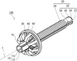
図1〜図5は本発明の実施の形態1に係るグロメットの構造を模式的に説明するものであって、図1は斜め前方から見た斜視図、図2は斜め後方から見た斜視図、図3は側面視の断面図、図4は側面視の断面図、図5は一部(連結部)を拡大して示す側面視の断面図である。
[Embodiment 1]
1 to 5 schematically illustrate the structure of a grommet according to
(全体構成)
図1および図2において、グロメット100は、自動車等の車両の車体パネルに形成された貫通孔を貫通したワイヤハーネス(いずれも図示しない)を保護するためのものである。以下、グロメット100は、車外側(後方)から車内側(前方)に向かって貫通孔8に押し込まれる場合について説明する。なお、本発明は車体パネル9に形成された貫通孔8に限定して装着されるものではなく、各種構造物や各種装置に形成された貫通孔にも装着されるものである。
(overall structure)
1 and 2, a
(室内側ハーネス挿通部および室外側ハーネス挿通部)
図1および図2おいて、室内側ハーネス挿通部10は、断面円弧状の円弧片12によって構成され、円弧片12の側縁同士の間には、軸方向に平行な挿通部スリット13が形成されている。そして、後端19(図3参照)においてリップ山基盤30が一体化している。
また、室外側ハーネス挿通部20は、前端21と中間位置23(図3参照)との間におけるスリットのない円筒部分22と、円筒部分22に接続されたコルゲート部分24と、コルゲート部分24に接続されたスリット部分25とを具備している。スリット部分25には一対の貫通孔28が形成され、貫通孔28と後端29との間に軸方向に平行なスリット27が形成されている。すなわち、スリット27に挟まれるように、断面半円状の円弧片26が形成されている。
そして、室内側ハーネス挿通部10の中心軸と室外側ハーネス挿通部20の中心軸とは一致しているため、以下、これを「中心軸1」と称し、中心軸1に近づく方向あるいは近い位置を「内側」または「内」、中心軸1から離れる方向あるいは離れた位置を「外側」または「外」と称す。また、室内側ハーネス挿通部10の側を「室内側」、室外側ハーネス挿通部20の側を「室外側」と称す。なお、「一体化」とは、別部位が一体的に連続した状態で成形された場合と、別部位がそれぞれ別個に形成された後、相互に接続された場合とがあり、以下、「接続されている」あるいは「つながっている」等と称す場合がある。
以下、図3〜図5に基づいて、各部位を詳細に説明する。
(Indoor harness insertion section and outdoor harness insertion section)
1 and 2, the indoor
Further, the outdoor-side
Since the center axis of the indoor side
Hereinafter, each part will be described in detail with reference to FIGS.
(リップ山)
リップ山70は正面視において略矩形状であって、リップ山基盤30の室内側に突出し、リップ山基盤30に円周方向の8個所に等角配置され、主にリップ山基盤30の剛性を高めている。
そして、リップ山70は側面視において、リップ山内周71がリップ山基盤30に接続され、室内側になる程徐々に外側になるリップ山内面72と、リップ山内面72に連続して中心軸1に垂直なリップ山室内側面73と、リップ山室内側面73とリップ山外面75とを結びつけるリップ山円弧面74とを具備している。なお、リップ山外面75は室外側(連結部40)に近づく程徐々に拡径する(外側になる)略直線を呈している。
(Lip Mountain)
The
In a side view, the
(中間リブ)
リップ山基盤30の室外側には中間リブ80が円周方向の8個所に等角配置されている。このとき、リップ山70と中間リブ80とは円周方向で同一位相になっている。中間リブ80は側面視において、内周81と、室外側面82と、中間位置83より外側で室外側の突出した突出部分84とを具備している。突出部分84は主にリップ山基盤30の剛性を高めるためのものである。なお、中間リブ80の設置を省略してもよい。
(Intermediate rib)
(パネル当接部)
パネル当接部50は側面視において、作業部60の外周69に内周51が一体化され、中心軸1に垂直な薄肉部分52と、薄肉部分52の外周(以下「中間位置53」と称す)に一体化した厚肉部分54とを具備している。そして、厚肉部分54は薄肉部分52よりも室内側に突出して中心軸1に垂直なパネル当接面55を具備している。さらに、パネル当接面55の外周59(正確には外周59に近い所定の幅の範囲)には、室内側に向かって突出した円環状のパネル当接突起56が形成されている。
そして、リップ山70、連結部40およびパネル当接部50(または作業部60)によって空間部57が形成されている。
(Panel abutment part)
The
A
(作業部および作業押圧部)
作業部60は略ベル形状で、内周61が室外側ハーネス挿通部20の中間位置23に接続され、外周69がパネル当接部50の内周51に一体的に接続されている。そして、側面62は、室外側になる程徐々に内側に近づいている。なお、外周69および内周51は、説明の便宜上規定した仮想の面であって、位置が厳密に特定されるものではない(その他の接合、についても、仮想の面同士が接合するような説明をしている)。
作業部60の側面62と室外側ハーネス挿通部20の円筒部分22とに跨がって複数の作業押圧部90が一体化されている。作業押圧部90は、放射状に配置された板状体であって、室外側ハーネス挿通部20の円筒部分22に接続された内周91と、作業部60の外周69に一体化した外周99と、中心軸1に対して垂直な室内側面92とを具備している。なお、室内側面92はパネル当接部50の薄肉部分52と略同一の面に位置しているが、リップ山70に向かって突出してもよい。
(Working part and work pressing part)
The working
A plurality of
(連結部)
図5において、連結部40はリップ山70とパネル当接部50とを連結するものである。すなわち、連結部40は、前面41がリップ山基盤30に接続され、後面49がパネル当接部50に(中間位置53寄りの範囲において)接続されている。
連結部40は薄肉の円筒であって、室外側になる程徐々に内側になるように傾斜した傾斜部分42と、傾斜部分42につながって中心軸1に平行な平行部分43とを具備している。そして、平行部分43の外面に突出した突起部分44が形成されている。また、傾斜部分42と中間リブ80の突出部分84との間に隙間45が形成されている。
そして、リップ山外面75と傾斜部分42とは断面略円弧状の山形状部分46によって滑らかにつながっている。このとき、山形状部分46は所定の剛性を具備している。
なお、前面41および後面49等は一体的に接続された位置を示す説明の便宜上規定した仮想の面であって、それらの位置が厳密に特定されるものではない。また、突起部分44の形状は図示された断面半円状に限定されるものではなく、断面矩形状や断面台形状であってもよい。
(Connecting part)
In FIG. 5, a connecting
The connecting
The lip
The
(装着要領)
図6は本発明の実施の形態1に係るグロメットの装着要領を模式的に説明する側面視の断面図であって、中心軸1より下側は装着開始当初、中心軸1より上側は装着中をそれぞれ示している。
図6の中心軸1より下側に示す装着開始当初において、リップ山70が貫通孔8に押し込まれている。貫通孔8にはフランジ6が設けられていて、以下の説明便宜上、フランジ6の室内側の端部を「貫通孔前端7a」と、室外側の端部を「貫通孔後端7b」と称す。すなわち、リップ山70のリップ山円弧面74が、貫通孔後端7bに当接している。
(How to install)
FIG. 6 is a side view sectional view schematically illustrating a grommet mounting procedure according to the first embodiment of the present invention. The lower side of the
At the beginning of the mounting shown below the
図6の中心軸1よりも上側に示す装着中において、リップ山70が貫通孔8にさらに押し込まれている。このため、リップ山円弧面74は貫通孔内周7に摺動しながら室内側に移動して縮径され、引き続き、山形状部分46が内側にたわんで貫通孔内周7に摺動することになる。
したがって、さらに押し込まれると、山形状部分46は貫通孔内周7から外れて、貫通孔前端7aを乗り越えるから、傾斜部分42が貫通孔前端7aに食い込むように当接して、連結部40が貫通孔内周7に嵌合することになる。また、突起部分44は貫通孔内周7に密着し、同時に、パネル当接部50のパネル当接突起56は車体パネル9の室外側の面(以下「パネル室外側面9b」と称す)に密着する(これについては別途詳細に説明する)
During the mounting shown above the
Therefore, when it is further pushed in, the mountain-shaped
(嵌合形態)
図7は本発明の実施の形態1に係るグロメットの嵌合形態を模式的に説明する側面視の断面図である。
図7において、連結部40が貫通孔8(図6参照)に嵌合している。このとき、押し込みは終了し、リップ山70(リップ山基盤30)は弾性復元している。すなわち、山形状部分46が貫通孔内周7に摺動している間は、リップ山70の外周79は縮径していたものの、山形状部分46が貫通孔前端7aを過ぎると、山形状部分46は弾性復元して拡径する。そうすると、貫通孔前端7aは傾斜部分42に食い込むように当接する。また、貫通孔内周7は突起部分44に押し当てられ、パネル室外側面9bはパネル当接突起56に押し当てられることになる。
なお、グロメット100は弾性体であるから、突起部分44は弾性変形する。このため、突起部分44の最も突出した位置は、装着開始前は線状であったものが、装着終了時には所定の幅の面状の範囲になっている。
(Mating form)
FIG. 7 is a side sectional view schematically illustrating a fitting form of the grommet according to
7, the connecting
Since the
(作用効果)
以上のように、グロメット100は、リップ山外面75と傾斜部分42とを滑らかにつなぐ山形状部分46を具備し、山形状部分46は所定の剛性を具備して傾斜部分42を支えているから、貫通孔前端7aは傾斜部分42に強く食い込むように当接する。また貫通孔8を形成するフランジ6は室外側に押されるから、パネル室外側面9bはパネル当接突起56に押し付けられる。さらに、貫通孔内周7は突起部分44を圧縮している。
すなわち、グロメット100は、パネル当接部50のパネル当接突起56と、連結部40の傾斜部分42と、連結部40の突起部分44との3点において勘合機構が形成されて車体パネル9に装着されるから、装着が確実かつ容易で、半嵌合等が防止される。よって、優れた止水性を奏する。
(Effects)
As described above, since the
That is, the
(従来技術における嵌合形態についての補足説明)
図8および図9は、本発明の実施の形態1に係るグロメットの勘合形態について従来技術の勘合形態との相違を模式的に説明するものであって、図8は従来技術において室内側に引っ張って装着した状態を示す一部の断面図、図9は従来技術において室外側から押し込んで装着した状態を示す一部の断面図である。なお、実施の形態1と同じ部位または相当する部位には同じ名称および同じ符号を付し、一部説明を省略する。
図8および図9において、従来技術におけるグロメット900が具備する連結部40は、中心軸1に対して外側になる程僅かに室外側になるように傾斜したオーバーハング部分47と、オーバーハング部分47につながった平行部分43と、平行部分43に形成された突起部分44とを具備している。そして、リップ山70とオーバーハング部分47との間には、外側に突出した返し形状部分48が形成されている。
(Supplementary explanation of fitting form in conventional technology)
FIG. 8 and FIG. 9 schematically illustrate the difference between the fitting form of the grommet according to the first embodiment of the present invention and the fitting form of the prior art, and FIG. FIG. 9 is a partial cross-sectional view showing a state of being mounted by pushing in from the outside in the prior art. The same parts or corresponding parts as in the first embodiment are given the same names and the same reference numerals, and a part of the description is omitted.
8 and 9, the connecting
(室内側に引っ張って装着する際)
図8において、グロメット900を車体パネル9の貫通孔8に室内側に引っ張って装着する際、リップ山外面75および連結部40は引っ張られて縮径しながら、室内側に移動するから、フランジ6(貫通孔内周7に同じ)は、オーバーハング部分47を平行部分43と平行になる方向に押し倒すことになる。このとき、返し形状部分48は後方に移動されるものの、連結部40(特に平行部分43)は引き伸ばされているため、返し形状部分48とパネル当接突起56との距離は、フランジ6の長さ(貫通孔前端7aと貫通孔後端7bとの距離に同じ)よりも長くなる。すなわち、フランジ6は連結部40に落ち込み可能な状態になる。
そうすると、貫通孔前端7aが返し形状部分48を通過したところで、返し形状部分48は弾性復元して拡径するため、見かけ上、フランジ6はオーバーハング部分47とパネル当接突起56との間に侵入する。そうすると、貫通孔内周7は突起部分44に当接する。また、オーバーハング部分47も弾性復元するから、貫通孔前端7aがオーバーハング部分47に当接する。
さらに、室内側に引っ張る力がなくなると、連結部40(特に平行部分43)は収縮するため、貫通孔前端7aがオーバーハング部分47に食い込み、貫通孔内周7が突起部分44に押し付けられ、車体パネル9がパネル当接突起56に押し付けられ、かかる3点において勘合機構が形成される。このとき、オーバーハング部分47がパネル室外側面9bをパネル当接突起56に押し当てている。
(When pulling indoors for mounting)
In FIG. 8, when the
Then, when the
Further, when the pulling force to the indoor side is lost, the connecting portion 40 (particularly, the parallel portion 43) contracts, so that the
(室外側から押し込んで装着する際)
図9において、グロメット900を車体パネル9の貫通孔8に室外側から押し込んで装着する際、連結部40(正確には、リップ山外面75の貫通孔後端7bに当接した位置とパネル当接面55との間)には圧縮力が作用し、リップ山外面75は貫通孔内周7に摺動する。このため、リップ山外面75は徐々に縮径し、オーバーハング部分47を平行部分43と平行になる方向(両者のなす角度が鋭角になる方向)に押し倒すことになる。
このとき、返し形状部分48は見かけ上室外側に押しやられるため、返し形状部分48とパネル当接突起56との距離は、フランジ6の長さ(貫通孔前端7aと貫通孔後端7bとの距離に同じ)よりも短くなる。すなわち、フランジ6は連結部40に落ち込み不可能な状態になる。
そうすると、パネル室外側面9bがパネル当接突起56に当接した状態では、貫通孔前端7aは返し形状部分48に当接したままで、返し形状部分48は貫通孔前端7aを通過して貫通孔内周7に摺動することができない。すなわち、見かけ上、フランジ6はオーバーハング部分47とパネル当接突起56との間に侵入することができない。そうすると、室外側から押し込む力がなくなって、連結部40(特に平行部分43)に作用していた圧縮力がなくなると、貫通孔前端7aはオーバーハング部分47に食い込んだままで、貫通孔内周7が突起部分44に当接することはない。
よって、グロメット900を室外側から押し込むと、室内側に引っ張って装着した場合のような3点における勘合機構が形成されることがないから、半嵌合状態を招き止水性が劣るため、後方から押し込んで装着することに不向きであった。
(When pushing in from the outside and mounting)
In FIG. 9, when the
At this time, since the turned-
Then, when the panel chamber
Therefore, when the
以上、本発明を実施の形態1をもとに説明した。この実施の形態1は例示であり、それらの各構成要素およびその組合せにいろいろな変形例が可能なこと、またそうした変形例も本発明の範囲にあることは当業者に理解されるところである。 The present invention has been described based on the first embodiment. The first embodiment is an exemplification, and it will be understood by those skilled in the art that various modifications can be made to the components and combinations thereof, and that such modifications are also within the scope of the present invention.
本発明は以上であるから、様々な構造物における板材に形成された貫通孔に装着される各種グロメットとして広く利用することができる。 As described above, the present invention can be widely used as various grommets mounted on through holes formed in plate members of various structures.
1 :中心軸
6 :フランジ
7 :貫通孔内周
7a:貫通孔前端
7b:貫通孔後端
8 :貫通孔
9 :車体パネル
9b:パネル室外側面
10 :室内側ハーネス挿通部
12 :円弧片
13 :挿通部スリット
19 :後端
20 :室外側ハーネス挿通部
21 :前端
22 :円筒部分
23 :中間位置
24 :コルゲート部分
25 :スリット部分
26 :円弧片
27 :スリット
28 :貫通孔
29 :後端
30 :リップ山基盤
40 :連結部
41 :前面
42 :傾斜部分
43 :平行部分
44 :突起部分
45 :連結部隙間
46 :山形状部分
47 :オーバーハング部分(従来技術)
48 :返し形状部分(従来技術)
49 :後面
50 :パネル当接部
51 :内周
52 :薄肉部分
53 :中間位置
54 :厚肉部分
55 :パネル当接面
56 :パネル当接突起
57 :空間部
59 :外周
60 :作業部
61 :内周
62 :側面
69 :外周
70 :リップ山
71 :リップ山内周
72 :リップ山内面
73 :リップ山室内側面
74 :リップ山円弧面
75 :リップ山外面
79 :外周
80 :中間リブ
81 :内周
82 :室外側面
83 :中間位置
84 :突出部分
90 :作業押圧部
91 :内周
92 :室内側面
99 :外周
100 :グロメット
900 :グロメット(従来技術)
1: Central axis 6: Flange 7: Inner circumference of through
48: Return shape part (conventional technology)
49: rear surface 50: panel contact portion 51: inner periphery 52: thin portion 53: intermediate position 54: thick portion 55: panel contact surface 56: panel contact protrusion 57: space portion 59: outer periphery 60: working portion 61 : Inner circumference 62: side surface 69: outer circumference 70: lip ridge 71: lip ridge inner circumference 72: lip ridge inner surface 73: lip ridge inner side surface 74: lip ridge arc surface 75: lip ridge outer surface 79: outer circumference 80: intermediate rib 81: inside Circumference 82: Outdoor side surface 83: Intermediate position 84: Projecting portion 90: Work pressing portion 91: Inner periphery 92: Indoor side surface 99: Outer periphery 100: Grommet 900: Grommet (prior art)
Claims (2)
ワイヤハーネスが貫通し、室内側に突出した室内側ハーネス挿通部および室外側に突出した室外側ハーネス挿通部と、
前記室内側ハーネス挿通部に一体化したリップ山と、
前記車体パネルの室外側における前記貫通孔の周囲に当接するパネル当接部と、
前記リップ山と前記パネル当接部とを連結する連結部と、
前記室外側ハーネス挿通部と前記パネル当接部とに跨がって形成された作業部と、
前記室外側ハーネス挿通部および前記作業部に一体化した作業押圧部とを備え、
前記連結部は前記パネル当接部に近づく程徐々に縮径する傾斜部分と、前記傾斜部分につながって外径が一定の平行部分と、前記平行部分に形成されて外側に突出した突起部分とを具備し、
前記リップ山と前記傾斜部分とは断面略円弧状の山形状部分によって滑らかにつながっていることを特徴とするグロメット。 A grommet attached to a through hole formed in the vehicle body panel,
A wire harness penetrates, and an indoor side harness insertion portion protruding to the indoor side and an outdoor side harness insertion portion protruding to the outdoor side,
A lip mountain integrated with the indoor harness insertion portion,
A panel contact portion that contacts the periphery of the through hole on the outdoor side of the vehicle body panel;
A connecting portion for connecting the lip ridge and the panel contact portion,
A working part formed astride the outdoor harness insertion part and the panel contact part,
A work pressing portion integrated with the outdoor harness insertion portion and the work portion,
The connecting portion has an inclined portion that gradually decreases in diameter as approaching the panel contact portion, a parallel portion connected to the inclined portion and having a constant outer diameter, and a protruding portion formed in the parallel portion and protruding outward. With
A grommet characterized in that the lip ridge and the inclined portion are smoothly connected by a ridge portion having a substantially arc-shaped cross section.
前記貫通孔に装着される際、前記山形状部分は前記フランジに摺動して内側に撓み、
前記貫通孔に装着された状態で、前記山形状部分および前記突起部分が前記フランジに密着することを特徴とする請求項1記載のグロメット。 A flange is formed around the through hole,
When mounted in the through hole, the mountain-shaped portion slides on the flange and flexes inward,
The grommet according to claim 1, wherein the mountain-shaped portion and the protruding portion are in close contact with the flange when the grommet is mounted in the through hole.
Priority Applications (3)
| Application Number | Priority Date | Filing Date | Title |
|---|---|---|---|
| JP2018168717A JP2020043676A (en) | 2018-09-10 | 2018-09-10 | Grommet |
| CN201910846884.5A CN110884446A (en) | 2018-09-10 | 2019-09-09 | Protective ring |
| US16/564,313 US20200079304A1 (en) | 2018-09-10 | 2019-09-09 | Grommet |
Applications Claiming Priority (1)
| Application Number | Priority Date | Filing Date | Title |
|---|---|---|---|
| JP2018168717A JP2020043676A (en) | 2018-09-10 | 2018-09-10 | Grommet |
Publications (1)
| Publication Number | Publication Date |
|---|---|
| JP2020043676A true JP2020043676A (en) | 2020-03-19 |
Family
ID=69719127
Family Applications (1)
| Application Number | Title | Priority Date | Filing Date |
|---|---|---|---|
| JP2018168717A Pending JP2020043676A (en) | 2018-09-10 | 2018-09-10 | Grommet |
Country Status (3)
| Country | Link |
|---|---|
| US (1) | US20200079304A1 (en) |
| JP (1) | JP2020043676A (en) |
| CN (1) | CN110884446A (en) |
Cited By (1)
| Publication number | Priority date | Publication date | Assignee | Title |
|---|---|---|---|---|
| US11279302B2 (en) | 2019-05-09 | 2022-03-22 | Yazaki Corporation | Grommet and wire harness |
Families Citing this family (4)
| Publication number | Priority date | Publication date | Assignee | Title |
|---|---|---|---|---|
| JP7117337B2 (en) * | 2020-02-03 | 2022-08-12 | 矢崎総業株式会社 | Grommet and wire harness |
| JP7159235B2 (en) * | 2020-02-17 | 2022-10-24 | 矢崎総業株式会社 | Grommet and wire harness |
| JP2021129478A (en) * | 2020-02-17 | 2021-09-02 | 矢崎総業株式会社 | Grommets and wire harnesses |
| GB2606055B (en) * | 2021-03-01 | 2025-01-29 | Caterpillar Inc | A grommet |
Citations (8)
| Publication number | Priority date | Publication date | Assignee | Title |
|---|---|---|---|---|
| JPH10302563A (en) * | 1997-04-22 | 1998-11-13 | Yazaki Corp | Grommet |
| JPH11266517A (en) * | 1998-03-17 | 1999-09-28 | Sumitomo Wiring Syst Ltd | Grommet |
| JP2004320951A (en) * | 2003-04-18 | 2004-11-11 | Sumitomo Wiring Syst Ltd | Grommet |
| JP2005006359A (en) * | 2003-06-09 | 2005-01-06 | Yazaki Corp | Grommet |
| JP2005019088A (en) * | 2003-06-24 | 2005-01-20 | Yazaki Corp | Grommet |
| JP2009017682A (en) * | 2007-07-04 | 2009-01-22 | Yazaki Corp | Grommet |
| JP2009296740A (en) * | 2008-06-03 | 2009-12-17 | Sumitomo Wiring Syst Ltd | Grommet |
| US20180126929A1 (en) * | 2016-11-09 | 2018-05-10 | GM Global Technology Operations LLC | Push Through Grommet |
Family Cites Families (2)
| Publication number | Priority date | Publication date | Assignee | Title |
|---|---|---|---|---|
| JP2010073664A (en) * | 2008-09-22 | 2010-04-02 | Sumitomo Wiring Syst Ltd | Waterproof connector and rubber stopper |
| JP2017220976A (en) * | 2016-06-03 | 2017-12-14 | 矢崎総業株式会社 | Grommet manufacturing method and grommet |
-
2018
- 2018-09-10 JP JP2018168717A patent/JP2020043676A/en active Pending
-
2019
- 2019-09-09 CN CN201910846884.5A patent/CN110884446A/en active Pending
- 2019-09-09 US US16/564,313 patent/US20200079304A1/en not_active Abandoned
Patent Citations (8)
| Publication number | Priority date | Publication date | Assignee | Title |
|---|---|---|---|---|
| JPH10302563A (en) * | 1997-04-22 | 1998-11-13 | Yazaki Corp | Grommet |
| JPH11266517A (en) * | 1998-03-17 | 1999-09-28 | Sumitomo Wiring Syst Ltd | Grommet |
| JP2004320951A (en) * | 2003-04-18 | 2004-11-11 | Sumitomo Wiring Syst Ltd | Grommet |
| JP2005006359A (en) * | 2003-06-09 | 2005-01-06 | Yazaki Corp | Grommet |
| JP2005019088A (en) * | 2003-06-24 | 2005-01-20 | Yazaki Corp | Grommet |
| JP2009017682A (en) * | 2007-07-04 | 2009-01-22 | Yazaki Corp | Grommet |
| JP2009296740A (en) * | 2008-06-03 | 2009-12-17 | Sumitomo Wiring Syst Ltd | Grommet |
| US20180126929A1 (en) * | 2016-11-09 | 2018-05-10 | GM Global Technology Operations LLC | Push Through Grommet |
Cited By (1)
| Publication number | Priority date | Publication date | Assignee | Title |
|---|---|---|---|---|
| US11279302B2 (en) | 2019-05-09 | 2022-03-22 | Yazaki Corporation | Grommet and wire harness |
Also Published As
| Publication number | Publication date |
|---|---|
| CN110884446A (en) | 2020-03-17 |
| US20200079304A1 (en) | 2020-03-12 |
Similar Documents
| Publication | Publication Date | Title |
|---|---|---|
| JP2020043676A (en) | Grommet | |
| CN104541423B (en) | Grommet | |
| CN100458192C (en) | Device for connecting a support and an accessory | |
| JP2020043675A (en) | Grommet | |
| JP5633353B2 (en) | Grommet | |
| SE515653C2 (en) | Sealing ring for mounting on the outside of a pipe piece | |
| JP2002354635A (en) | Grommet | |
| WO2014175045A1 (en) | Grommet | |
| WO2016183924A1 (en) | Floating adjustable sealing mechanism and connector using same | |
| JP2011089543A (en) | Clip | |
| JP4950017B2 (en) | Connector and circuit board mounting case with connector | |
| JP6424793B2 (en) | Grommet and wire harness | |
| US9942637B2 (en) | L-brackets for mounting with extended mobility range | |
| CN110890731B (en) | grommet | |
| EP0844693A2 (en) | Waterproof plug | |
| JP2020036478A (en) | Grommet | |
| CN110226060A (en) | Plugs | |
| JP5898850B2 (en) | Pipe fitting | |
| KR101950699B1 (en) | Grommet for Vehicle | |
| JP3196620B2 (en) | Grommet | |
| JPH10255573A (en) | Grommet for wire harness | |
| JP6508962B2 (en) | Fastening structure of bolt to resin plate | |
| WO2022181362A1 (en) | Grommet | |
| JP3246304B2 (en) | Grommet | |
| CN210517209U (en) | a curved connector |
Legal Events
| Date | Code | Title | Description |
|---|---|---|---|
| A621 | Written request for application examination |
Free format text: JAPANESE INTERMEDIATE CODE: A621 Effective date: 20200117 |
|
| A977 | Report on retrieval |
Free format text: JAPANESE INTERMEDIATE CODE: A971007 Effective date: 20201021 |
|
| A131 | Notification of reasons for refusal |
Free format text: JAPANESE INTERMEDIATE CODE: A131 Effective date: 20201027 |
|
| A02 | Decision of refusal |
Free format text: JAPANESE INTERMEDIATE CODE: A02 Effective date: 20210427 |