JP2020062964A - Battery cooling system - Google Patents
Battery cooling system Download PDFInfo
- Publication number
- JP2020062964A JP2020062964A JP2018196153A JP2018196153A JP2020062964A JP 2020062964 A JP2020062964 A JP 2020062964A JP 2018196153 A JP2018196153 A JP 2018196153A JP 2018196153 A JP2018196153 A JP 2018196153A JP 2020062964 A JP2020062964 A JP 2020062964A
- Authority
- JP
- Japan
- Prior art keywords
- battery
- oil pump
- oil
- electric
- temperature
- Prior art date
- Legal status (The legal status is an assumption and is not a legal conclusion. Google has not performed a legal analysis and makes no representation as to the accuracy of the status listed.)
- Granted
Links
Images






Classifications
-
- B—PERFORMING OPERATIONS; TRANSPORTING
- B60—VEHICLES IN GENERAL
- B60L—PROPULSION OF ELECTRICALLY-PROPELLED VEHICLES; SUPPLYING ELECTRIC POWER FOR AUXILIARY EQUIPMENT OF ELECTRICALLY-PROPELLED VEHICLES; ELECTRODYNAMIC BRAKE SYSTEMS FOR VEHICLES IN GENERAL; MAGNETIC SUSPENSION OR LEVITATION FOR VEHICLES; MONITORING OPERATING VARIABLES OF ELECTRICALLY-PROPELLED VEHICLES; ELECTRIC SAFETY DEVICES FOR ELECTRICALLY-PROPELLED VEHICLES
- B60L58/00—Methods or circuit arrangements for monitoring or controlling batteries or fuel cells, specially adapted for electric vehicles
- B60L58/10—Methods or circuit arrangements for monitoring or controlling batteries or fuel cells, specially adapted for electric vehicles for monitoring or controlling batteries
- B60L58/24—Methods or circuit arrangements for monitoring or controlling batteries or fuel cells, specially adapted for electric vehicles for monitoring or controlling batteries for controlling the temperature of batteries
- B60L58/26—Methods or circuit arrangements for monitoring or controlling batteries or fuel cells, specially adapted for electric vehicles for monitoring or controlling batteries for controlling the temperature of batteries by cooling
-
- H—ELECTRICITY
- H01—ELECTRIC ELEMENTS
- H01M—PROCESSES OR MEANS, e.g. BATTERIES, FOR THE DIRECT CONVERSION OF CHEMICAL ENERGY INTO ELECTRICAL ENERGY
- H01M10/00—Secondary cells; Manufacture thereof
- H01M10/60—Heating or cooling; Temperature control
- H01M10/66—Heat-exchange relationships between the cells and other systems, e.g. central heating systems or fuel cells
-
- B—PERFORMING OPERATIONS; TRANSPORTING
- B60—VEHICLES IN GENERAL
- B60K—ARRANGEMENT OR MOUNTING OF PROPULSION UNITS OR OF TRANSMISSIONS IN VEHICLES; ARRANGEMENT OR MOUNTING OF PLURAL DIVERSE PRIME-MOVERS IN VEHICLES; AUXILIARY DRIVES FOR VEHICLES; INSTRUMENTATION OR DASHBOARDS FOR VEHICLES; ARRANGEMENTS IN CONNECTION WITH COOLING, AIR INTAKE, GAS EXHAUST OR FUEL SUPPLY OF PROPULSION UNITS IN VEHICLES
- B60K11/00—Arrangement in connection with cooling of propulsion units
- B60K11/02—Arrangement in connection with cooling of propulsion units with liquid cooling
-
- B—PERFORMING OPERATIONS; TRANSPORTING
- B60—VEHICLES IN GENERAL
- B60L—PROPULSION OF ELECTRICALLY-PROPELLED VEHICLES; SUPPLYING ELECTRIC POWER FOR AUXILIARY EQUIPMENT OF ELECTRICALLY-PROPELLED VEHICLES; ELECTRODYNAMIC BRAKE SYSTEMS FOR VEHICLES IN GENERAL; MAGNETIC SUSPENSION OR LEVITATION FOR VEHICLES; MONITORING OPERATING VARIABLES OF ELECTRICALLY-PROPELLED VEHICLES; ELECTRIC SAFETY DEVICES FOR ELECTRICALLY-PROPELLED VEHICLES
- B60L58/00—Methods or circuit arrangements for monitoring or controlling batteries or fuel cells, specially adapted for electric vehicles
- B60L58/10—Methods or circuit arrangements for monitoring or controlling batteries or fuel cells, specially adapted for electric vehicles for monitoring or controlling batteries
- B60L58/24—Methods or circuit arrangements for monitoring or controlling batteries or fuel cells, specially adapted for electric vehicles for monitoring or controlling batteries for controlling the temperature of batteries
- B60L58/27—Methods or circuit arrangements for monitoring or controlling batteries or fuel cells, specially adapted for electric vehicles for monitoring or controlling batteries for controlling the temperature of batteries by heating
-
- F—MECHANICAL ENGINEERING; LIGHTING; HEATING; WEAPONS; BLASTING
- F01—MACHINES OR ENGINES IN GENERAL; ENGINE PLANTS IN GENERAL; STEAM ENGINES
- F01M—LUBRICATING OF MACHINES OR ENGINES IN GENERAL; LUBRICATING INTERNAL COMBUSTION ENGINES; CRANKCASE VENTILATING
- F01M5/00—Heating, cooling, or controlling temperature of lubricant; Lubrication means facilitating engine starting
-
- F—MECHANICAL ENGINEERING; LIGHTING; HEATING; WEAPONS; BLASTING
- F01—MACHINES OR ENGINES IN GENERAL; ENGINE PLANTS IN GENERAL; STEAM ENGINES
- F01M—LUBRICATING OF MACHINES OR ENGINES IN GENERAL; LUBRICATING INTERNAL COMBUSTION ENGINES; CRANKCASE VENTILATING
- F01M5/00—Heating, cooling, or controlling temperature of lubricant; Lubrication means facilitating engine starting
- F01M5/002—Cooling
-
- F—MECHANICAL ENGINEERING; LIGHTING; HEATING; WEAPONS; BLASTING
- F16—ENGINEERING ELEMENTS AND UNITS; GENERAL MEASURES FOR PRODUCING AND MAINTAINING EFFECTIVE FUNCTIONING OF MACHINES OR INSTALLATIONS; THERMAL INSULATION IN GENERAL
- F16H—GEARING
- F16H57/00—General details of gearing
- F16H57/04—Features relating to lubrication or cooling or heating
- F16H57/0467—Elements of gearings to be lubricated, cooled or heated
- F16H57/0476—Electric machines and gearing, i.e. joint lubrication or cooling or heating thereof
-
- F—MECHANICAL ENGINEERING; LIGHTING; HEATING; WEAPONS; BLASTING
- F16—ENGINEERING ELEMENTS AND UNITS; GENERAL MEASURES FOR PRODUCING AND MAINTAINING EFFECTIVE FUNCTIONING OF MACHINES OR INSTALLATIONS; THERMAL INSULATION IN GENERAL
- F16N—LUBRICATING
- F16N13/00—Lubricating-pumps
- F16N13/22—Lubricating-pumps with distributing equipment
-
- F—MECHANICAL ENGINEERING; LIGHTING; HEATING; WEAPONS; BLASTING
- F16—ENGINEERING ELEMENTS AND UNITS; GENERAL MEASURES FOR PRODUCING AND MAINTAINING EFFECTIVE FUNCTIONING OF MACHINES OR INSTALLATIONS; THERMAL INSULATION IN GENERAL
- F16N—LUBRICATING
- F16N17/00—Lubrication of machines or apparatus working under extreme conditions
- F16N17/02—Lubrication of machines or apparatus working under extreme conditions at high temperature
-
- F—MECHANICAL ENGINEERING; LIGHTING; HEATING; WEAPONS; BLASTING
- F16—ENGINEERING ELEMENTS AND UNITS; GENERAL MEASURES FOR PRODUCING AND MAINTAINING EFFECTIVE FUNCTIONING OF MACHINES OR INSTALLATIONS; THERMAL INSULATION IN GENERAL
- F16N—LUBRICATING
- F16N29/00—Special means in lubricating arrangements or systems providing for the indication or detection of undesired conditions; Use of devices responsive to conditions in lubricating arrangements or systems
-
- F—MECHANICAL ENGINEERING; LIGHTING; HEATING; WEAPONS; BLASTING
- F16—ENGINEERING ELEMENTS AND UNITS; GENERAL MEASURES FOR PRODUCING AND MAINTAINING EFFECTIVE FUNCTIONING OF MACHINES OR INSTALLATIONS; THERMAL INSULATION IN GENERAL
- F16N—LUBRICATING
- F16N39/00—Arrangements for conditioning of lubricants in the lubricating system
-
- F—MECHANICAL ENGINEERING; LIGHTING; HEATING; WEAPONS; BLASTING
- F16—ENGINEERING ELEMENTS AND UNITS; GENERAL MEASURES FOR PRODUCING AND MAINTAINING EFFECTIVE FUNCTIONING OF MACHINES OR INSTALLATIONS; THERMAL INSULATION IN GENERAL
- F16N—LUBRICATING
- F16N39/00—Arrangements for conditioning of lubricants in the lubricating system
- F16N39/02—Arrangements for conditioning of lubricants in the lubricating system by cooling
-
- F—MECHANICAL ENGINEERING; LIGHTING; HEATING; WEAPONS; BLASTING
- F16—ENGINEERING ELEMENTS AND UNITS; GENERAL MEASURES FOR PRODUCING AND MAINTAINING EFFECTIVE FUNCTIONING OF MACHINES OR INSTALLATIONS; THERMAL INSULATION IN GENERAL
- F16N—LUBRICATING
- F16N7/00—Arrangements for supplying oil or unspecified lubricant from a stationary reservoir or the equivalent in or on the machine or member to be lubricated
- F16N7/38—Arrangements for supplying oil or unspecified lubricant from a stationary reservoir or the equivalent in or on the machine or member to be lubricated with a separate pump; Central lubrication systems
- F16N7/40—Arrangements for supplying oil or unspecified lubricant from a stationary reservoir or the equivalent in or on the machine or member to be lubricated with a separate pump; Central lubrication systems in a closed circulation system
-
- H—ELECTRICITY
- H01—ELECTRIC ELEMENTS
- H01M—PROCESSES OR MEANS, e.g. BATTERIES, FOR THE DIRECT CONVERSION OF CHEMICAL ENERGY INTO ELECTRICAL ENERGY
- H01M10/00—Secondary cells; Manufacture thereof
- H01M10/42—Methods or arrangements for servicing or maintenance of secondary cells or secondary half-cells
- H01M10/48—Accumulators combined with arrangements for measuring, testing or indicating the condition of cells, e.g. the level or density of the electrolyte
- H01M10/486—Accumulators combined with arrangements for measuring, testing or indicating the condition of cells, e.g. the level or density of the electrolyte for measuring temperature
-
- H—ELECTRICITY
- H01—ELECTRIC ELEMENTS
- H01M—PROCESSES OR MEANS, e.g. BATTERIES, FOR THE DIRECT CONVERSION OF CHEMICAL ENERGY INTO ELECTRICAL ENERGY
- H01M10/00—Secondary cells; Manufacture thereof
- H01M10/60—Heating or cooling; Temperature control
- H01M10/61—Types of temperature control
- H01M10/613—Cooling or keeping cold
-
- H—ELECTRICITY
- H01—ELECTRIC ELEMENTS
- H01M—PROCESSES OR MEANS, e.g. BATTERIES, FOR THE DIRECT CONVERSION OF CHEMICAL ENERGY INTO ELECTRICAL ENERGY
- H01M10/00—Secondary cells; Manufacture thereof
- H01M10/60—Heating or cooling; Temperature control
- H01M10/61—Types of temperature control
- H01M10/615—Heating or keeping warm
-
- H—ELECTRICITY
- H01—ELECTRIC ELEMENTS
- H01M—PROCESSES OR MEANS, e.g. BATTERIES, FOR THE DIRECT CONVERSION OF CHEMICAL ENERGY INTO ELECTRICAL ENERGY
- H01M10/00—Secondary cells; Manufacture thereof
- H01M10/60—Heating or cooling; Temperature control
- H01M10/62—Heating or cooling; Temperature control specially adapted for specific applications
- H01M10/625—Vehicles
-
- H—ELECTRICITY
- H01—ELECTRIC ELEMENTS
- H01M—PROCESSES OR MEANS, e.g. BATTERIES, FOR THE DIRECT CONVERSION OF CHEMICAL ENERGY INTO ELECTRICAL ENERGY
- H01M10/00—Secondary cells; Manufacture thereof
- H01M10/60—Heating or cooling; Temperature control
- H01M10/63—Control systems
-
- H—ELECTRICITY
- H01—ELECTRIC ELEMENTS
- H01M—PROCESSES OR MEANS, e.g. BATTERIES, FOR THE DIRECT CONVERSION OF CHEMICAL ENERGY INTO ELECTRICAL ENERGY
- H01M10/00—Secondary cells; Manufacture thereof
- H01M10/60—Heating or cooling; Temperature control
- H01M10/63—Control systems
- H01M10/633—Control systems characterised by algorithms, flow charts, software details or the like
-
- H—ELECTRICITY
- H01—ELECTRIC ELEMENTS
- H01M—PROCESSES OR MEANS, e.g. BATTERIES, FOR THE DIRECT CONVERSION OF CHEMICAL ENERGY INTO ELECTRICAL ENERGY
- H01M10/00—Secondary cells; Manufacture thereof
- H01M10/60—Heating or cooling; Temperature control
- H01M10/63—Control systems
- H01M10/635—Control systems based on ambient temperature
-
- H—ELECTRICITY
- H01—ELECTRIC ELEMENTS
- H01M—PROCESSES OR MEANS, e.g. BATTERIES, FOR THE DIRECT CONVERSION OF CHEMICAL ENERGY INTO ELECTRICAL ENERGY
- H01M10/00—Secondary cells; Manufacture thereof
- H01M10/60—Heating or cooling; Temperature control
- H01M10/65—Means for temperature control structurally associated with the cells
- H01M10/655—Solid structures for heat exchange or heat conduction
- H01M10/6552—Closed pipes transferring heat by thermal conductivity or phase transition, e.g. heat pipes
-
- H—ELECTRICITY
- H01—ELECTRIC ELEMENTS
- H01M—PROCESSES OR MEANS, e.g. BATTERIES, FOR THE DIRECT CONVERSION OF CHEMICAL ENERGY INTO ELECTRICAL ENERGY
- H01M10/00—Secondary cells; Manufacture thereof
- H01M10/60—Heating or cooling; Temperature control
- H01M10/65—Means for temperature control structurally associated with the cells
- H01M10/656—Means for temperature control structurally associated with the cells characterised by the type of heat-exchange fluid
- H01M10/6567—Liquids
- H01M10/6568—Liquids characterised by flow circuits, e.g. loops, located externally to the cells or cell casings
-
- H—ELECTRICITY
- H01—ELECTRIC ELEMENTS
- H01M—PROCESSES OR MEANS, e.g. BATTERIES, FOR THE DIRECT CONVERSION OF CHEMICAL ENERGY INTO ELECTRICAL ENERGY
- H01M10/00—Secondary cells; Manufacture thereof
- H01M10/60—Heating or cooling; Temperature control
- H01M10/66—Heat-exchange relationships between the cells and other systems, e.g. central heating systems or fuel cells
- H01M10/663—Heat-exchange relationships between the cells and other systems, e.g. central heating systems or fuel cells the system being an air-conditioner or an engine
-
- B—PERFORMING OPERATIONS; TRANSPORTING
- B60—VEHICLES IN GENERAL
- B60K—ARRANGEMENT OR MOUNTING OF PROPULSION UNITS OR OF TRANSMISSIONS IN VEHICLES; ARRANGEMENT OR MOUNTING OF PLURAL DIVERSE PRIME-MOVERS IN VEHICLES; AUXILIARY DRIVES FOR VEHICLES; INSTRUMENTATION OR DASHBOARDS FOR VEHICLES; ARRANGEMENTS IN CONNECTION WITH COOLING, AIR INTAKE, GAS EXHAUST OR FUEL SUPPLY OF PROPULSION UNITS IN VEHICLES
- B60K1/00—Arrangement or mounting of electrical propulsion units
-
- B—PERFORMING OPERATIONS; TRANSPORTING
- B60—VEHICLES IN GENERAL
- B60K—ARRANGEMENT OR MOUNTING OF PROPULSION UNITS OR OF TRANSMISSIONS IN VEHICLES; ARRANGEMENT OR MOUNTING OF PLURAL DIVERSE PRIME-MOVERS IN VEHICLES; AUXILIARY DRIVES FOR VEHICLES; INSTRUMENTATION OR DASHBOARDS FOR VEHICLES; ARRANGEMENTS IN CONNECTION WITH COOLING, AIR INTAKE, GAS EXHAUST OR FUEL SUPPLY OF PROPULSION UNITS IN VEHICLES
- B60K1/00—Arrangement or mounting of electrical propulsion units
- B60K2001/003—Arrangement or mounting of electrical propulsion units with means for cooling the electrical propulsion units
- B60K2001/005—Arrangement or mounting of electrical propulsion units with means for cooling the electrical propulsion units the electric storage means
-
- B—PERFORMING OPERATIONS; TRANSPORTING
- B60—VEHICLES IN GENERAL
- B60K—ARRANGEMENT OR MOUNTING OF PROPULSION UNITS OR OF TRANSMISSIONS IN VEHICLES; ARRANGEMENT OR MOUNTING OF PLURAL DIVERSE PRIME-MOVERS IN VEHICLES; AUXILIARY DRIVES FOR VEHICLES; INSTRUMENTATION OR DASHBOARDS FOR VEHICLES; ARRANGEMENTS IN CONNECTION WITH COOLING, AIR INTAKE, GAS EXHAUST OR FUEL SUPPLY OF PROPULSION UNITS IN VEHICLES
- B60K1/00—Arrangement or mounting of electrical propulsion units
- B60K2001/003—Arrangement or mounting of electrical propulsion units with means for cooling the electrical propulsion units
- B60K2001/006—Arrangement or mounting of electrical propulsion units with means for cooling the electrical propulsion units the electric motors
-
- F—MECHANICAL ENGINEERING; LIGHTING; HEATING; WEAPONS; BLASTING
- F16—ENGINEERING ELEMENTS AND UNITS; GENERAL MEASURES FOR PRODUCING AND MAINTAINING EFFECTIVE FUNCTIONING OF MACHINES OR INSTALLATIONS; THERMAL INSULATION IN GENERAL
- F16H—GEARING
- F16H57/00—General details of gearing
- F16H57/04—Features relating to lubrication or cooling or heating
- F16H57/0402—Cleaning of lubricants, e.g. filters or magnets
- F16H57/0404—Lubricant filters
-
- F—MECHANICAL ENGINEERING; LIGHTING; HEATING; WEAPONS; BLASTING
- F16—ENGINEERING ELEMENTS AND UNITS; GENERAL MEASURES FOR PRODUCING AND MAINTAINING EFFECTIVE FUNCTIONING OF MACHINES OR INSTALLATIONS; THERMAL INSULATION IN GENERAL
- F16H—GEARING
- F16H57/00—General details of gearing
- F16H57/04—Features relating to lubrication or cooling or heating
- F16H57/0412—Cooling or heating; Control of temperature
- F16H57/0413—Controlled cooling or heating of lubricant; Temperature control therefor
-
- F—MECHANICAL ENGINEERING; LIGHTING; HEATING; WEAPONS; BLASTING
- F16—ENGINEERING ELEMENTS AND UNITS; GENERAL MEASURES FOR PRODUCING AND MAINTAINING EFFECTIVE FUNCTIONING OF MACHINES OR INSTALLATIONS; THERMAL INSULATION IN GENERAL
- F16H—GEARING
- F16H57/00—General details of gearing
- F16H57/04—Features relating to lubrication or cooling or heating
- F16H57/0412—Cooling or heating; Control of temperature
- F16H57/0415—Air cooling or ventilation; Heat exchangers; Thermal insulations
- F16H57/0417—Heat exchangers adapted or integrated in the gearing
-
- F—MECHANICAL ENGINEERING; LIGHTING; HEATING; WEAPONS; BLASTING
- F16—ENGINEERING ELEMENTS AND UNITS; GENERAL MEASURES FOR PRODUCING AND MAINTAINING EFFECTIVE FUNCTIONING OF MACHINES OR INSTALLATIONS; THERMAL INSULATION IN GENERAL
- F16H—GEARING
- F16H57/00—General details of gearing
- F16H57/04—Features relating to lubrication or cooling or heating
- F16H57/0434—Features relating to lubrication or cooling or heating relating to lubrication supply, e.g. pumps; Pressure control
- F16H57/0435—Pressure control for supplying lubricant; Circuits or valves therefor
-
- F—MECHANICAL ENGINEERING; LIGHTING; HEATING; WEAPONS; BLASTING
- F16—ENGINEERING ELEMENTS AND UNITS; GENERAL MEASURES FOR PRODUCING AND MAINTAINING EFFECTIVE FUNCTIONING OF MACHINES OR INSTALLATIONS; THERMAL INSULATION IN GENERAL
- F16H—GEARING
- F16H57/00—General details of gearing
- F16H57/04—Features relating to lubrication or cooling or heating
- F16H57/0434—Features relating to lubrication or cooling or heating relating to lubrication supply, e.g. pumps; Pressure control
- F16H57/0441—Arrangements of pumps
-
- F—MECHANICAL ENGINEERING; LIGHTING; HEATING; WEAPONS; BLASTING
- F16—ENGINEERING ELEMENTS AND UNITS; GENERAL MEASURES FOR PRODUCING AND MAINTAINING EFFECTIVE FUNCTIONING OF MACHINES OR INSTALLATIONS; THERMAL INSULATION IN GENERAL
- F16N—LUBRICATING
- F16N39/00—Arrangements for conditioning of lubricants in the lubricating system
- F16N2039/007—Using strainers
-
- F—MECHANICAL ENGINEERING; LIGHTING; HEATING; WEAPONS; BLASTING
- F16—ENGINEERING ELEMENTS AND UNITS; GENERAL MEASURES FOR PRODUCING AND MAINTAINING EFFECTIVE FUNCTIONING OF MACHINES OR INSTALLATIONS; THERMAL INSULATION IN GENERAL
- F16N—LUBRICATING
- F16N2210/00—Applications
- F16N2210/04—Vehicles
-
- F—MECHANICAL ENGINEERING; LIGHTING; HEATING; WEAPONS; BLASTING
- F16—ENGINEERING ELEMENTS AND UNITS; GENERAL MEASURES FOR PRODUCING AND MAINTAINING EFFECTIVE FUNCTIONING OF MACHINES OR INSTALLATIONS; THERMAL INSULATION IN GENERAL
- F16N—LUBRICATING
- F16N2210/00—Applications
- F16N2210/12—Gearings
-
- F—MECHANICAL ENGINEERING; LIGHTING; HEATING; WEAPONS; BLASTING
- F16—ENGINEERING ELEMENTS AND UNITS; GENERAL MEASURES FOR PRODUCING AND MAINTAINING EFFECTIVE FUNCTIONING OF MACHINES OR INSTALLATIONS; THERMAL INSULATION IN GENERAL
- F16N—LUBRICATING
- F16N2210/00—Applications
- F16N2210/18—Electric motors
-
- F—MECHANICAL ENGINEERING; LIGHTING; HEATING; WEAPONS; BLASTING
- F16—ENGINEERING ELEMENTS AND UNITS; GENERAL MEASURES FOR PRODUCING AND MAINTAINING EFFECTIVE FUNCTIONING OF MACHINES OR INSTALLATIONS; THERMAL INSULATION IN GENERAL
- F16N—LUBRICATING
- F16N2270/00—Controlling
- F16N2270/60—Pressure
-
- F—MECHANICAL ENGINEERING; LIGHTING; HEATING; WEAPONS; BLASTING
- F16—ENGINEERING ELEMENTS AND UNITS; GENERAL MEASURES FOR PRODUCING AND MAINTAINING EFFECTIVE FUNCTIONING OF MACHINES OR INSTALLATIONS; THERMAL INSULATION IN GENERAL
- F16N—LUBRICATING
- F16N2270/00—Controlling
- F16N2270/70—Supply
-
- F—MECHANICAL ENGINEERING; LIGHTING; HEATING; WEAPONS; BLASTING
- F16—ENGINEERING ELEMENTS AND UNITS; GENERAL MEASURES FOR PRODUCING AND MAINTAINING EFFECTIVE FUNCTIONING OF MACHINES OR INSTALLATIONS; THERMAL INSULATION IN GENERAL
- F16N—LUBRICATING
- F16N39/00—Arrangements for conditioning of lubricants in the lubricating system
- F16N39/06—Arrangements for conditioning of lubricants in the lubricating system by filtration
-
- H—ELECTRICITY
- H01—ELECTRIC ELEMENTS
- H01M—PROCESSES OR MEANS, e.g. BATTERIES, FOR THE DIRECT CONVERSION OF CHEMICAL ENERGY INTO ELECTRICAL ENERGY
- H01M2220/00—Batteries for particular applications
- H01M2220/20—Batteries in motive systems, e.g. vehicle, ship, plane
-
- Y—GENERAL TAGGING OF NEW TECHNOLOGICAL DEVELOPMENTS; GENERAL TAGGING OF CROSS-SECTIONAL TECHNOLOGIES SPANNING OVER SEVERAL SECTIONS OF THE IPC; TECHNICAL SUBJECTS COVERED BY FORMER USPC CROSS-REFERENCE ART COLLECTIONS [XRACs] AND DIGESTS
- Y02—TECHNOLOGIES OR APPLICATIONS FOR MITIGATION OR ADAPTATION AGAINST CLIMATE CHANGE
- Y02E—REDUCTION OF GREENHOUSE GAS [GHG] EMISSIONS, RELATED TO ENERGY GENERATION, TRANSMISSION OR DISTRIBUTION
- Y02E60/00—Enabling technologies; Technologies with a potential or indirect contribution to GHG emissions mitigation
- Y02E60/10—Energy storage using batteries
-
- Y—GENERAL TAGGING OF NEW TECHNOLOGICAL DEVELOPMENTS; GENERAL TAGGING OF CROSS-SECTIONAL TECHNOLOGIES SPANNING OVER SEVERAL SECTIONS OF THE IPC; TECHNICAL SUBJECTS COVERED BY FORMER USPC CROSS-REFERENCE ART COLLECTIONS [XRACs] AND DIGESTS
- Y02—TECHNOLOGIES OR APPLICATIONS FOR MITIGATION OR ADAPTATION AGAINST CLIMATE CHANGE
- Y02T—CLIMATE CHANGE MITIGATION TECHNOLOGIES RELATED TO TRANSPORTATION
- Y02T10/00—Road transport of goods or passengers
- Y02T10/60—Other road transportation technologies with climate change mitigation effect
- Y02T10/70—Energy storage systems for electromobility, e.g. batteries
Landscapes
- Engineering & Computer Science (AREA)
- Chemical & Material Sciences (AREA)
- Manufacturing & Machinery (AREA)
- Chemical Kinetics & Catalysis (AREA)
- Electrochemistry (AREA)
- General Chemical & Material Sciences (AREA)
- General Engineering & Computer Science (AREA)
- Mechanical Engineering (AREA)
- Transportation (AREA)
- Automation & Control Theory (AREA)
- Life Sciences & Earth Sciences (AREA)
- Sustainable Development (AREA)
- Sustainable Energy (AREA)
- Power Engineering (AREA)
- Combustion & Propulsion (AREA)
- Secondary Cells (AREA)
- Electric Propulsion And Braking For Vehicles (AREA)
- Cooling, Air Intake And Gas Exhaust, And Fuel Tank Arrangements In Propulsion Units (AREA)
- Arrangement Or Mounting Of Propulsion Units For Vehicles (AREA)
Abstract
【課題】簡素なシステム構成で電池の冷却と暖機とを行うこと。【解決手段】トランスアクスルを潤滑するためのオイルを電池の冷却に用いる電池冷却システムであって、循環回路内で、オイルクーラを経由せずに、トランスアクスルと電池とへオイルを供給する第1油路に設けられた第1電動オイルポンプと、循環回路内で、オイルクーラを経由して、トランスアクスルと電池とへオイルを供給する第2油路に設けられた第2電動オイルポンプと、第1電動オイルポンプおよび第2電動オイルポンプを制御する制御部と、を備え、制御部は、電池セルの温度が所定値以下の場合(ステップS1:Yes)、第1電動オイルポンプを作動させ、かつ第2電動オイルポンプを停止させ(ステップS2)、電池セルの温度が所定値よりも高い場合(ステップS1:No)、第1電動オイルポンプを停止させ、かつ第2電動オイルポンプを作動させる(ステップS3)。【選択図】図4PROBLEM TO BE SOLVED: To cool and warm up a battery with a simple system configuration. A battery cooling system that uses oil for lubricating a transaxle to cool a battery, and supplies oil to a transaxle and a battery in a circulation circuit without passing through an oil cooler. A first electric oil pump provided in the oil passage, and a second electric oil pump provided in a second oil passage that supplies oil to the transaxle and the battery in the circulation circuit via an oil cooler; A control unit that controls the first electric oil pump and the second electric oil pump, and the control unit operates the first electric oil pump when the temperature of the battery cell is equal to or lower than a predetermined value (step S1: Yes). If the temperature of the battery cell is higher than a predetermined value (step S1: No), the second electric oil pump is stopped, and the first electric oil pump is stopped. Actuating the second electric oil pump (step S3). [Selection diagram] Fig. 4
Description
本発明は、電池冷却システムに関する。 The present invention relates to a battery cooling system.
特許文献1には、車両に搭載された電池冷却システムについて、トランスアクスルを潤滑するためのオイルをバッテリユニットの冷却に用いることが開示されている。
ところで、バッテリユニットを構成する電池セルは、温度が低くなると、電圧が降下するため、電池セルを暖機することが必要になる場合がある。しかしながら、特許文献1に記載に構成では、トランスアクスル、オイルクーラ、バッテリユニットの間が閉ループの回路構成となるため、冷却専用の回路となり、電池セルの暖機を考慮したものではなかった。そこで、電池セルの冷却と暖機とを行うことが可能な回路構成とすることが考えられるが、この場合には電池セルの温度に応じた制御が必要になるため、例えば切替弁(電磁弁)やその切り替えに必要な回路などを設けると、複雑なシステム構成となる虞がある。
By the way, when the temperature of the battery cells forming the battery unit becomes low, the voltage drops, so it may be necessary to warm up the battery cells. However, the configuration described in
本発明は、上記事情に鑑みてなされたものであって、簡素なシステム構成で電池の冷却と暖機とを行うことが可能な電池冷却システムを提供することを目的とする。 The present invention has been made in view of the above circumstances, and an object of the present invention is to provide a battery cooling system capable of cooling and warming up a battery with a simple system configuration.
本発明は、トランスアクスル、電池、およびオイルクーラに共通のオイルを循環させる循環回路を備え、前記トランスアクスルを潤滑するための前記オイルを前記電池の冷却に用いる電池冷却システムであって、前記循環回路内で、前記オイルクーラを経由せずに、前記トランスアクスルと前記電池とに前記オイルを供給する第1油路に設けられた第1電動オイルポンプと、前記循環回路内で、前記オイルクーラを経由して、前記トランスアクスルと前記電池とに前記オイルを供給する第2油路に設けられた第2電動オイルポンプと、前記第1電動オイルポンプおよび前記第2電動オイルポンプを制御する制御部と、を備え、前記制御部は、前記電池の温度が第1所定値以下の場合に、前記第1電動オイルポンプを作動させ、かつ前記第2電動オイルポンプを停止させ、前記電池の温度が第1所定値よりも高い場合に、前記第1電動オイルポンプを停止させ、かつ前記第2電動オイルポンプを作動させることを特徴とする。 The present invention provides a battery cooling system, comprising a circulation circuit for circulating oil common to a transaxle, a battery, and an oil cooler, wherein the oil for lubricating the transaxle is used for cooling the battery. A first electric oil pump provided in a first oil passage for supplying the oil to the transaxle and the battery without passing through the oil cooler in the circuit, and the oil cooler in the circulation circuit. Control for controlling the second electric oil pump provided in the second oil passage for supplying the oil to the transaxle and the battery via the first electric oil pump and the second electric oil pump. And a control unit that activates the first electric oil pump when the temperature of the battery is equal to or lower than a first predetermined value, and controls the second electric oil pump. The oil pump is stopped, the temperature of the battery is higher than the first predetermined value, said first electric oil pump is stopped, and is characterized by operating the second electric oil pump.
また、前記トランスアクスルを収容するケースの内部に設けられた電動機、をさらに備え、前記オイルは、前記電動機の冷却に用いられ、前記制御部は、前記電池の温度が前記第1所定値以下、かつ前記電動機の温度が第2所定値よりも高い場合には、前記第1電動オイルポンプおよび前記第2電動オイルポンプを作動させ、前記第2所定値は、前記第1所定値以上の温度であってもよい。 Further, further comprising an electric motor provided inside a case accommodating the transaxle, the oil is used for cooling the electric motor, and the controller controls the temperature of the battery to be equal to or lower than the first predetermined value. Further, when the temperature of the electric motor is higher than the second predetermined value, the first electric oil pump and the second electric oil pump are operated, and the second predetermined value is a temperature equal to or higher than the first predetermined value. It may be.
この構成によれば、第1電動オイルポンプと第2電動オイルポンプとを同時に作動させることによって、第1電動オイルポンプからの温かいオイルと第2電動オイルポンプからの冷たいオイルとを足し合わせて電池に供給することができる。これにより、電池の温度を最適な温度に安定させることができる。 According to this configuration, by simultaneously operating the first electric oil pump and the second electric oil pump, the warm oil from the first electric oil pump and the cold oil from the second electric oil pump are added together, so that the battery Can be supplied to. As a result, the temperature of the battery can be stabilized at the optimum temperature.
また、前記循環回路では、前記電池の流入口よりも上流側に設けられた合流点で、前記第1油路と前記第2油路とが合流しており、前記制御部は、前記第1電動オイルポンプおよび前記第2電動オイルポンプを作動させる際、前記第1電動オイルポンプから吐出されたオイルの前記合流点での圧力と前記第2電動オイルポンプから吐出されたオイルの前記合流点での圧力とが等しくなるように、前記第1電動オイルポンプの吐出量および前記第2電動オイルポンプの吐出量を制御してもよい。 Further, in the circulation circuit, the first oil passage and the second oil passage meet at a joining point provided on the upstream side of the inlet of the battery, and the control unit controls the first oil passage. When operating the electric oil pump and the second electric oil pump, at the pressure at the confluence of the oil discharged from the first electric oil pump and the confluence of the oil discharged from the second electric oil pump. The discharge amount of the first electric oil pump and the discharge amount of the second electric oil pump may be controlled so that the pressure becomes equal.
この構成によれば、オイルクーラを経由しないオイルとオイルクーラを経由したオイルとを合流点で合流させてから電池とトランスアクスルとに供給することができる。これにより、電池の温度変化を安定させつつ、電動機の冷却を行うことができる。 According to this configuration, the oil not passing through the oil cooler and the oil passing through the oil cooler can be joined at the joining point and then supplied to the battery and the transaxle. This makes it possible to cool the electric motor while stabilizing the temperature change of the battery.
また、前記制御部は、前記電池の温度が前記第1所定値以下、かつ前記電動機の温度が第2所定値以下の場合には、前記第1電動オイルポンプを作動させ、かつ前記第2電動オイルポンプを停止させてもよい。 Further, the control unit operates the first electric oil pump and operates the second electric motor when the temperature of the battery is equal to or lower than the first predetermined value and the temperature of the electric motor is equal to or lower than a second predetermined value. The oil pump may be stopped.
この構成によれば、電動機の温度が高温側で余裕がある場合には、第1電動オイルポンプのみを作動して、電動機の冷却よりも電池の暖機を優先することができる。 According to this configuration, when the temperature of the electric motor is high on the high temperature side, only the first electric oil pump is operated, and the warming up of the battery can be prioritized over the cooling of the electric motor.
また、前記制御部は、前記電池の温度が第1所定値以上の場合には、前記電動機の温度に拘らず、前記第1電動オイルポンプを停止させ、かつ前記第2電動オイルポンプを作動させてもよい。 In addition, when the temperature of the battery is equal to or higher than a first predetermined value, the control unit stops the first electric oil pump and operates the second electric oil pump regardless of the temperature of the electric motor. May be.
この構成によれば、電池の温度が高温側で余裕がない場合には、第2電動オイルポンプのみを作動して、電池の冷却を優先することができる。 According to this configuration, when the battery temperature is high and there is no margin, only the second electric oil pump can be operated to prioritize battery cooling.
本発明では、電池の温度に応じて第1電動オイルポンプと第2電動オイルポンプとの作動を切り替えることによって、電池の冷却と暖機とを容易に切り替えることができる。また、各電動オイルポンプの作動を制御すればよく、例えば切替弁(電磁弁)の制御が不要なため、制御が簡素になる。さらに、切替弁等を設置する必要がなくなるため、循環回路が簡素になる。 In the present invention, the operation of the first electric oil pump and the operation of the second electric oil pump are switched according to the temperature of the battery, so that cooling and warming up of the battery can be easily switched. Further, the operation of each electric oil pump may be controlled, and, for example, the control of the switching valve (electromagnetic valve) is not required, so that the control is simplified. Furthermore, since it is not necessary to install a switching valve or the like, the circulation circuit is simplified.
以下、図面を参照して、本発明の実施形態における電池冷却システムについて具体的に説明する。 Hereinafter, a battery cooling system according to an embodiment of the present invention will be specifically described with reference to the drawings.
(第1実施形態)
図1は、第1実施形態の電池冷却システムを模式的に示す構成図である。図2は、トランスアクスルケース内での循環回路を模式的に示す図である。なお、図1では、電池の冷却と暖機との区別なく油路内にオイルが流れている状態を太線で示している。
(First embodiment)
FIG. 1 is a configuration diagram schematically showing the battery cooling system of the first embodiment. FIG. 2 is a diagram schematically showing a circulation circuit in the transaxle case. It should be noted that in FIG. 1, the state in which the oil flows in the oil passage without distinction between cooling the battery and warming up the battery is indicated by a thick line.
第1実施形態の電池冷却システム1は、電気自動車に搭載された冷却システムであり、トランスアクスル2を潤滑するためのオイルを電池3の冷却および暖機に用いるように構成されている。図1に示すように、電池冷却システム1は、トランスアクスル2と電池3との間でオイルが循環する循環回路10と、電池3の温度に応じて電池3の冷却と暖機とを切り替える制御を実施するECU20とを備える。この電池冷却システム1は、切替弁等を用いずに、電池3の冷却と暖機とを切り替えることが可能なシステムである。
The
トランスアクスル2は、トランスアクスルケース2a内に収容された変速機などの動力伝達機構を含んで構成されており、減速ギヤ21と、デファレンシャル機構(デフ)22とを備える。減速ギヤ21とデファレンシャル機構22とはオイルによる潤滑が必要な潤滑必要部である。減速ギヤ21はギヤ対を含んで構成される。循環回路10を循環するオイルはトランスアクスルケース2a内で一時的に貯留される。
The
トランスアクスルケース2aの内部には、動力源として機能するモータ4が収容されている。モータ4は、モータ・ジェネレータであり、発電機能を有する。モータ4はオイルによる冷却が必要な冷却必要部である。そして、モータ4は電池3に蓄えられている電力を使用して駆動する。モータ4から出力された動力はトランスアクスル2に入力され、トランスアクスル2から車輪(図示せず)に伝達される。このモータ4はECU20によって駆動制御される。この電気自動車では、動力伝達機構を構成する減速ギヤ21などの潤滑必要部と、冷却必要部であるモータ4とがトランスアクスルケース2a内に収容されたトランスアクスルユニットを搭載している。
A motor 4 functioning as a power source is housed inside the
電池3は、走行用のモータ4に供給するための電力を蓄える二次電池により構成される。電池3は、複数の電池セル33(図3に示す)により構成された電池モジュール31を複数備え、この複数の電池モジュール31が電池ケース32内に収容された電池パックにより構成されている。電池3に供給されたオイルは電池セル33の表面に触れるようにして各電池モジュール31内を流通する。なお、オイルは電池セル33の電極33a,33bには触れない位置を流れる。
The
循環回路10は、トランスアクスル2、電池3、オイルクーラ5に共通のオイルを循環させるオイル回路である。この循環回路10は、第1電動オイルポンプ(第1EOP)6と、第2電動オイルポンプ(第2EOP)7と、オイルクーラ5と、電池3と、モータ4と、減速ギヤ21と、デファレンシャル機構22と、を含む。
The
図1に示すように、循環回路10は、オイルクーラ5を経由しない油路である第1油路11と、オイルクーラ5を経由する油路である第2油路12とが並列に形成されている。第1油路11には第1電動オイルポンプ6が設けられている。第2油路12には第2電動オイルポンプ7が設けられている。そして、第1油路11と第2油路12とは合流点13で合流している。第1電動オイルポンプ6が作動することによりオイルクーラ5を経由せずに電池3へとオイルが供給される。第2油路12の第2電動オイルポンプ7が作動することによりオイルクーラ5を経由して電池3へとオイルが供給される。
As shown in FIG. 1, in the
第1電動オイルポンプ6は、暖機用のオイルポンプとして機能するものであり、トランスアクスルケース2aの内部に設けられている。第1電動オイルポンプ6は、トランスアクスルケース2a内に貯留されているオイルを、ストレーナ23を介して吸引し、第1油路11に吐出する。第1電動オイルポンプ6はECU20によって駆動制御される。ECU20は第1電動オイルポンプ6の吐出量を制御することができる。
The first
第2電動オイルポンプ7は、冷却用のオイルポンプとして機能するものであり、トランスアクスルケース2aの外部に設けられている。第2電動オイルポンプ7は、トランスアクスルケース2a内に貯留されているオイルを、ストレーナ23を介して吸引し、第2油路12に吐出する。第2電動オイルポンプ7はECU20によって駆動制御される。ECU20は第2電動オイルポンプ7の吐出量を制御することができる。例えば、第2電動オイルポンプ7はトランスアクスルケース2aに対して外付けのオイルポンプであり、第1電動オイルポンプ6よりも小型に構成されている。この場合の第1電動オイルポンプ6はトランスアクスルケース2a内に設けられた内蔵のオイルポンプである。
The second
第1油路11には、第1電動オイルポンプ6と、第1逆止弁8と、合流点13と、電池3と、トランスアクスル2とが設けられている。合流点13は、電池3の流入口と第1電動オイルポンプ6との間に設けられている。第1逆止弁8は、第1電動オイルポンプ6と電池3との間であって、合流点13よりも第1電動オイルポンプ6側に設けられている。第1電動オイルポンプ6が停止した状態で第2電動オイルポンプ7が作動する際、電池3側のオイルが第1電動オイルポンプ6の吐出口に向けて逆流しないように第1逆止弁8は閉じる。一方、第1電動オイルポンプ6が吐出したオイルは第1逆止弁8を介して電池3側へ圧送される。
The
第2油路12には、第2電動オイルポンプ7と、オイルクーラ5と、第2逆止弁9と、合流点13と、電池3と、トランスアクスル2とが設けられている。オイルクーラ5は、第2電動オイルポンプ7から吐出されたオイルを空冷するラジエータであり、オイルの熱を外気に放熱する。第2逆止弁9は、オイルクーラ5と電池3との間であって、合流点13よりもオイルクーラ5側に設けられている。第2電動オイルポンプ7が停止した状態で第1電動オイルポンプ6が作動する際、電池3側のオイルがオイルクーラ5の出口に向けて逆流しないように第2逆止弁9は閉じる。一方、第2電動オイルポンプ7が吐出したオイルはオイルクーラ5を経由して、第2逆止弁9を介して電池3側へ圧送される。
The
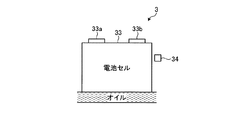
電池3へ流入したオイルは、電池ケース32内に収容されている複数の電池モジュール31を冷却してから電池ケース32の外部へ流出する。この場合、図3に示すように、電池モジュール31を構成する電池セル33の表面がオイルによって直接冷却される。暖機時には、電池セル33の表面がオイルによって直接暖機される。つまり、電池セル33の表面にオイルが接触する状態でオイルが流れる。また、電池3には、電池セル33の温度を検出する温度センサ34が設けられている。温度センサ34は、複数の電池モジュール31のうち、オイルの出側(下流側)に配置された電池モジュール31に設けられている。これにより、下流側であることによって相対的に高温になりやすい電池セル33を対象に電池セル33の温度を監視することができる。この温度センサ34からECU20にセンサ値(信号)が出力される。なお、この説明において、電池3の温度と電池セル33の温度とは同義である。
The oil flowing into the
電池3から流出したオイルは、トランスアクスルケース2aに戻り、トランスアクスルケース2aの内部でモータ4を冷却する。例えば、トランスアクスルケース2a内に戻ったオイルはモータ4のステータに冷却液として供給される。モータ4を冷却したオイルはトランスアクスルケース2aの下部(オイル貯留部)に一時的に貯留される。また、トランスアクスルケース2a内に戻ったオイルは、モータ4とは別に、減速ギヤ21やデファレンシャル機構22に潤滑油として供給される。ギヤ等を潤滑したオイルはトランスアクスルケース2aの下部(オイル貯留部)に一時的に貯留される。オイル貯留部に貯留されているオイルはストレーナ23を通って第1電動オイルポンプ6もしくは第2電動オイルポンプ7に吸引される。これにより、第1電動オイルポンプ6もしくは第2電動オイルポンプ7からトランスアクスルケース2aの外部へオイルが循環される。この循環回路10では、電気自動車の走行中に減速ギヤ21やデファレンシャル機構22などの潤滑必要部に潤滑油を供給し続けるために、第1電動オイルポンプ6と第2電動オイルポンプ7とのうち少なくともいずれか一方は作動していなければならない。
The oil flowing out from the
また、オイルは、絶縁性が高く、腐食性および金属反応性が低く、粘度が低く、潤滑性を有する液体である。例えば、低粘度な絶縁油(鉱物油や合成油)に、潤滑特性を付与するための添加剤を処方したオイルを、電池冷却用として循環回路10に使用する。より詳細には、電気特性については、このオイルは体積低効率が空気と同程度の値となり、LLC(冷却水)やエチレングリコールよりも高い値の体積低効率を有する。さらに、このオイルは破壊電圧が高い特性を有する。腐食性については、このオイルは銅板やアルミ板を腐食しない特性を有する。また、このオイルは吸水性が低い。反応性については、このオイルはリチウムや電解質とは反応しない特性を有する。さらに、このオイルは金属(例えば鉄、アルミニウム、銅)とは反応しない。
Further, oil is a liquid having a high insulating property, a low corrosive property and a low metal reactivity, a low viscosity, and a lubricating property. For example, an insulating oil (mineral oil or synthetic oil) having a low viscosity, which is formulated with an additive for imparting lubrication characteristics, is used in the
ECU20は、電気自動車に搭載された各種センサから入力される信号に基づいて電気自動車を制御する電子制御装置であり、電池3の暖機と冷却とを切り替える制御(切替制御)を実施する。この切替制御では、温度センサ34により検出した電池セル33の温度に基づいて、第1電動オイルポンプ6の作動と第2電動オイルポンプ7の作動とが切り替えられる。この場合、ECU20から各電動オイルポンプ6,7に指令信号が出力される。また、ECU20は第1電動オイルポンプ6を制御することによって第1電動オイルポンプ6の吐出量(流量)を変化させることができる。同様に、ECU20は第2電動オイルポンプ7を制御することによって第2電動オイルポンプ7の吐出量(流量)を変化させることができる。
The
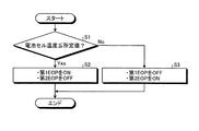
図4は、電動オイルポンプの作動制御フローを示すフローチャート図である。図4に示す制御フローはECU20によって実施される。
FIG. 4 is a flowchart showing an operation control flow of the electric oil pump. The control flow shown in FIG. 4 is executed by the
ECU20は、電池セル33の温度が所定値以下であるか否かを判定する(ステップS1)。所定値は、ある放電容量下において電池3の電圧が明確に低下する温度に設定されている。一例として、電池セル33が液体型リチウムイオン電池の場合、ステップS1の所定値を約5℃に設定することができる。このステップS1の所定値として設定される温度については図5を参照して説明する。
The
図5に示すように、電池3の放電容量が一定となる状況下において、電池セル33の温度が所定温度X℃よりも高い場合には、電池3の電圧は一定値に保たれる。一方、電池セル33の温度が所定温度X℃以下に低下すると、電池3の電圧は低下し始める。所定温度X℃を境にして電池3の電圧が明確に低下する。電池セル33の温度が所定温度X℃以下の場合、温度低下に応じて電圧がさらに低下する。このように、所定温度X℃の前後で電圧の大きさが明確に変化する。そこで、ステップS1の所定値として、所定温度X℃を設定することができる。
As shown in FIG. 5, when the temperature of the
図4に戻り、電池セル33の温度が所定値以下の場合(ステップS1:Yes)、ECU20は、第1電動オイルポンプ6を作動させ、かつ第2電動オイルポンプ7を停止する(ステップS2)。ステップS2では、第1電動オイルポンプ6のみを作動させて、トランスアクスル2の排熱によって電池3を暖機する。この場合には、オイルクーラ5を経由しないオイルのみが電池3に供給されることになる。ステップS2が実施されると、この制御ルーチンは終了する。
Returning to FIG. 4, when the temperature of the
電池セル33の温度が所定値よりも高い場合(ステップS1:No)、ECU20は、第1電動オイルポンプ6を停止し、かつ第2電動オイルポンプ7を作動させる(ステップS3)。ステップS3では、第2電動オイルポンプ7のみを作動させて、オイルクーラ5で放熱された後のオイルによって電池3を冷却する。この場合、オイルクーラ5を経由するオイルのみが電池3に供給されることになる。ステップS3が実施されると、この制御ルーチンは終了する。
When the temperature of the
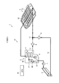
図6は、電池3を暖機する場合のオイルの流れを示す図である。なお、図6では油路内にオイルが流れている状態を太線で示し、油路内にオイルが流れていない状態を破線で示している。また、図6に示す状態は、上述したステップS2を実施した場合を表している。
FIG. 6 is a diagram showing an oil flow when warming up the
図6に示すように、電池3を暖機する場合には、二つの電動オイルポンプ6,7のうち第1電動オイルポンプ6のみが作動しているため、循環回路10のうち第1油路11を含む経路にオイルが流れる。すなわち、オイルクーラ5を経由しない経路をオイルが循環することになる。また、第2電動オイルポンプ7が停止しているため第2逆止弁9は閉じている。その結果、トランスアクスル2の排熱によって温度上昇したオイルがオイルクーラ5を経由せずに電池3へと供給されることになる。そのため、オイルの熱で電池3を暖機することができる。
As shown in FIG. 6, when warming up the
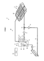
図7は、電池3を冷却する場合のオイルの流れを示す図である。なお、図7では、図6と同様に、油路内にオイルが流れている状態を太線で示し、油路内にオイルが流れていない状態を破線で示している。また、図6に示す状態は、上述したステップS3を実施した場合を表している。
FIG. 7 is a diagram showing the flow of oil when the
図7に示すように、電池3を冷却する場合には、二つの電動オイルポンプ6,7のうち第2電動オイルポンプ7のみが作動しているため、循環回路10のうち第2油路12を含む経路にオイルが流れる。すなわち、オイルクーラ5を経由する経路をオイルが循環することになる。また、第1電動オイルポンプ6が停止しているため第1逆止弁8は閉じている。その結果、オイルクーラ5で冷却されたオイルのみが電池3へと供給されることになる。そのため、電池3を効率的に冷却することができる。
As shown in FIG. 7, when the
以上説明した通り、第1実施形態によれば、電池セル33の温度に応じて第1電動オイルポンプ6および第2電動オイルポンプ7との作動と停止とを制御することによって、電池3の暖機と冷却とを切り替えることができる。つまり、二つの電動オイルポンプ6,7の作動を切り替えることによって電池3の暖機と冷却の回路を切り替えることができる。この結果、電池3の冷却と暖機との切り替えを、切替弁やその切り替えに必要な回路などを設けずに実施することが可能になる。これにより、簡素な回路構成の循環回路10を実現できる。そのため、簡素な冷却・暖機システムとなり、従来のシステム構成よりも軽量化、低コスト化が可能になる。電池3の冷却は熱劣化を防止するために必要である。電池3の暖機は電圧低下を防止するために必要である。
As described above, according to the first embodiment, the operation of the first
また、第1電動オイルポンプ6のみを作動することによってオイルクーラ5を通さずに電池3へオイルを供給できるので、トランスアクスル2の排熱で温められたオイルによって電池3を暖機できる。これにより、ヒータ等を設置する必要がなくなり、ヒータ等を作動させるためのエネルギーを削減できるため、従来のシステム構成よりも損失を低減できる。
Further, since the oil can be supplied to the
なお、上述した第1実施形態では、ステップS1の所定値として、所定温度X℃が設定される場合に限らず、温度範囲Yを設定することも可能である。温度範囲Yは、図5に示すように、所定温度X℃を含む温度範囲であって、例えば所定温度X℃のプラス数度(上限温度)から所定温度X℃のマイナス数度(下限温度)までを範囲とすることができる。この場合のステップS1では、電池セル33の温度が温度範囲Y以下であるか否かが判定される。すなわち、電池セル33の温度が温度範囲Yの上限温度以下であるか否かが判定される。温度範囲Yの上限値は所定温度Xよりも高いため、電池セル33の温度が温度範囲Yの上限値以下となった場合に電池セル33の暖機を開始することができる。これによって、所定温度Xよりも温度低下して電圧が低下し始める前に電池セル33を暖機し始めることができる。そのため、電池3の電圧低下を抑制することができる。
In the above-described first embodiment, the temperature range Y can be set as the predetermined value in step S1 without being limited to the case where the predetermined temperature X ° C. is set. As shown in FIG. 5, the temperature range Y is a temperature range including a predetermined temperature X ° C., for example, plus a few degrees (upper limit temperature) of the predetermined temperature X ° C. to minus a few degrees (lower limit temperature) of the predetermined temperature X ° C. Can range up to. In step S1 in this case, it is determined whether or not the temperature of the
また、電池冷却システム1では、トランスアクスルケース2aの内部に第1電動オイルポンプ6と第2電動オイルポンプ7とが両方とも設けられてもよい。あるいは、トランスアクスルケース2aの外部に第1電動オイルポンプ6と第2電動オイルポンプ7とが両方とも設けられてもよい。
Further, in the
さらに、電池冷却システム1が搭載される車両は、電気自動車に限らず、ハイブリッド自動車であってもよい。
Furthermore, the vehicle in which the
(第2実施形態)
第2実施形態の電池冷却システム1では、電池セル33の温度と、モータ4の温度とに基づいて、第1電動オイルポンプ6と第2電動オイルポンプ7との作動を切り替えるように構成されている。なお、第2実施形態の説明では、上述した第1実施形態と同様の構成については説明を省略し、その参照符号を引用する。
(Second embodiment)
The
第2実施形態のECU20は、モータ4の温度を検出する温度センサ41から信号が入力されるように構成されている。この温度センサ41は、例えばモータ4のコイルエンドに設けられた温度センサである。コイルエンドとは、ステータに巻き回されているコイルのうちステータの軸方向外側に突出している部分である。
The
また、ECU20は、電池3を保温する制御を実施するように構成されている。電池3の保温は、第1電動オイルポンプ6と第2電動オイルポンプ7とを両方とも作動することにより行われる。そして、ECU20は、電池セル33の温度とモータ4の温度とに基づいて、電池3の暖機と保温と冷却とを切り替える制御を実施するように構成されている。
Further, the
図8は、電動オイルポンプの作動制御フローを示すフローチャート図である。図8に示す制御フローはECU20によって実施される。
FIG. 8 is a flowchart showing an operation control flow of the electric oil pump. The control flow shown in FIG. 8 is executed by the
ECU20は、電池セル33の温度が第1所定値以下であるか否かを判定する(ステップS11)。このステップS11は、上述した図4のステップS1と同様の処理である。そのため、ステップS11の第1所定値は、上述したステップS1の所定値と同義である。また、ステップS11で電池セル33の温度と比較される所定値を第1所定値と表現することができる。
The
電池セル33の温度が第1所定値以下の場合(ステップS11:Yes)、ECU20は、モータ4の温度が第2所定値以下であるか否かを判定する(ステップS12)。ステップS12の第2所定値は、モータ4の温度と比較するための所定値である。この第2所定値は、上述したステップS11の第1所定値とは異なる値に設定することが可能である。ステップS12の第2所定値は、モータ4の冷却と電池3の冷却とのうちモータ4の冷却を優先することが望ましい所定温度、例えば第1所定値以上の温度に設定することができる。
When the temperature of the
モータ4の温度が第2所定値以下の場合(ステップS12:Yes)、ECU20は、第1電動オイルポンプ6を作動させ、かつ第2電動オイルポンプ7を停止する(ステップS13)。ステップS13の実施条件であるステップS12で肯定的に判定された場合とは、電池セル33の温度が第1所定値以下、かつモータ4の温度が第2所定値以下となる場合である。この場合に、例えば図9に示す第1温度状態(1)である場合に、ステップS13を実施することによって、電池3を暖機することになる。ステップS13が実施されると、この制御ルーチンは終了する。なお、図9の横軸である電池セル33の温度についての所定値(第1所定値に相当)と、図9の縦軸であるモータ4の温度についての所定値(第2所定値に相当)とは異なる値であってもよい。
When the temperature of the motor 4 is equal to or lower than the second predetermined value (step S12: Yes), the
モータ4の温度が第2所定値よりも高い場合(ステップS12:No)、ECU20は、第1電動オイルポンプ6を作動させ、かつ第2電動オイルポンプ7を作動させる(ステップS14)。ステップS14では、第1電動オイルポンプ6と第2電動オイルポンプ7とを両方とも作動させて、トランスアクスル2の排熱により温まったオイルと、オイルクーラ5で放熱された後のオイルとを合流させたオイルを電池3に供給し、電池3を保温することになる。
When the temperature of the motor 4 is higher than the second predetermined value (step S12: No), the
ステップS14の実施条件であるステップS12が否定的に判定された場合とは、電池セル33の温度が第1所定値以下、かつモータ4の温度が第2所定値よりも高い場合である。この場合に、例えば図9に示す第2温度状態(2)である場合に、ステップS14を実施することによって、電池3を少し温めつつ、電池3の冷却とモータ4の冷却とのうちモータ4の冷却を優先するになる。ステップS14が実施されると、この制御ルーチンは終了する。
The case where step S12 which is the execution condition of step S14 is negatively determined is the case where the temperature of the
また、電池セル33の温度が第1所定値よりも高い場合(ステップS11:No)、ECU20は、第1電動オイルポンプ6を停止し、かつ第2電動オイルポンプ7を作動させる(ステップS15)。
When the temperature of the
ステップS15の実施条件であるステップS11で否定的に判定された場合とは、電池セル33の温度が第1所定値よりも高い場合である。この場合に、例えば図9に示す第3温度状態(3)である場合に、ステップS15を実施することによって、電池3を冷却することになる。電池セル33の温度とモータ4の温度とを用いて、電池3の暖機と保温と冷却とを切り替える制御を実施する構成では、電池セル33の温度が第1所定値よりも高い場合には、モータ4の温度に拘らず、電池3の冷却を優先することになる。ステップS15が実施されると、この制御ルーチンは終了する。
The case where the determination in step S11, which is the implementation condition of step S15, is negative is when the temperature of the
図10は、電池3を保温する場合のオイルの流れを示す図である。なお、図10では、油路内にオイルが流れている状態を太線で示している。また、図10に示す状態は、上述したステップS14を実施した場合を表している。
FIG. 10 is a diagram showing the flow of oil when the
図10に示すように、電池3を保温する場合には、第1電動オイルポンプ6と第2電動オイルポンプ7とが両方とも作動して、第1逆止弁8と第2逆止弁9とが両方とも開くため、第1油路11を流れるオイルと第2油路12を流れるオイルとが合流点13で合流する。このとき、ECU20は、第1電動オイルポンプ6から吐出されたオイルの合流点13での圧力と、第2電動オイルポンプ7から吐出されたオイルの合流点13での圧力とが等しくなるように、第1電動オイルポンプ6の吐出量および第2電動オイルポンプ7の吐出量を制御する。例えば第2電動オイルポンプ7の吐出量が一定の場合には、ECU20は第1電動オイルポンプ6の吐出量を調整する。この場合、ECU20は、第2電動オイルポンプ7の吐出口から合流点13までの第2油路12の圧力損失と釣り合うように第1電動オイルポンプ6を作動させる。これにより、第1逆止弁8と第2逆止弁9とが両方とも開いた状態となり、合流点13で、第1電動オイルポンプ6からの流量と第2電動オイルポンプ7からの流量を足し合わせることができる。すなわち、合流点13で、トランスアクスル2の排熱により温まったオイルとオイルクーラ5で空冷されたオイルとが合流する。この合流後のオイルが電池3に供給される。
As shown in FIG. 10, when the
以上説明した通り、第2実施形態によれば、第1実施形態と同様の効果が得られるとともに、第1電動オイルポンプ6と第2電動オイルポンプ7とを同時に作動させることによって、電池3の温度を最適な温度に安定させることができる。
As described above, according to the second embodiment, the same effect as that of the first embodiment can be obtained, and the first
また、電池3を保温する目的で、第1電動オイルポンプ6と第2電動オイルポンプ7とを両方とも停止してしまうと、減速ギヤ21やデファレンシャル機構22などの潤滑必要部に潤滑油が供給されなくなり、潤滑性が低下する。これに対して第2実施形態では、電池3を保温する際に第1電動オイルポンプ6と第2電動オイルポンプ7とを両方とも作動させるため、電池3の温度を安定させつつ、十分量のオイルを潤滑必要部に供給することができる。そのため、トランスアクスル2の潤滑性能が低下することを抑制できる。これにより、共通のオイルを循環させる循環回路10について、電池3の温度管理とトランスアクスル2の潤滑性確保とを両立することができる。
Further, if both the first
なお、上述した第2実施形態では、ステップS12の第2所定値として、モータ4の温度についての温度範囲を設定することも可能である。要するに、上述した電池セル33の温度における温度範囲Yの場合と同様に、第2所定値についても所定の温度範囲とすることができる。
In the above-described second embodiment, the temperature range of the temperature of the motor 4 can be set as the second predetermined value in step S12. In short, similar to the case of the temperature range Y at the temperature of the
1 電池冷却システム
2 トランスアクスル
2a トランスアクスルケース
3 電池
4 モータ
5 オイルクーラ
6 第1電動オイルポンプ
7 第2電動オイルポンプ
8 第1逆止弁
9 第2逆止弁
10 循環回路
11 第1油路
12 第2油路
13 合流点
20 ECU
21 減速ギヤ
22 デファレンシャル機構
23 ストレーナ
31 電池モジュール
32 電池ケース
33 電池セル
1
21
Claims (5)
前記循環回路内で、前記オイルクーラを経由せずに、前記トランスアクスルと前記電池とに前記オイルを供給する第1油路に設けられた第1電動オイルポンプと、
前記循環回路内で、前記オイルクーラを経由して、前記トランスアクスルと前記電池とに前記オイルを供給する第2油路に設けられた第2電動オイルポンプと、
前記第1電動オイルポンプおよび前記第2電動オイルポンプを制御する制御部と、
を備え、
前記制御部は、
前記電池の温度が第1所定値以下の場合に、前記第1電動オイルポンプを作動させ、かつ前記第2電動オイルポンプを停止させ、
前記電池の温度が第1所定値よりも高い場合に、前記第1電動オイルポンプを停止させ、かつ前記第2電動オイルポンプを作動させる
ことを特徴とする電池冷却システム。 A battery cooling system, comprising a transaxle, a battery, and a circulation circuit for circulating oil common to an oil cooler, wherein the oil for lubricating the transaxle is used for cooling the battery,
A first electric oil pump provided in a first oil passage that supplies the oil to the transaxle and the battery without passing through the oil cooler in the circulation circuit;
A second electric oil pump provided in a second oil passage for supplying the oil to the transaxle and the battery via the oil cooler in the circulation circuit;
A control unit that controls the first electric oil pump and the second electric oil pump;
Equipped with
The control unit is
When the temperature of the battery is equal to or lower than a first predetermined value, the first electric oil pump is operated and the second electric oil pump is stopped,
A battery cooling system, wherein when the temperature of the battery is higher than a first predetermined value, the first electric oil pump is stopped and the second electric oil pump is operated.
前記オイルは、前記電動機の冷却に用いられ、
前記制御部は、前記電池の温度が前記第1所定値以下、かつ前記電動機の温度が第2所定値よりも高い場合には、前記第1電動オイルポンプおよび前記第2電動オイルポンプを作動させ、
前記第2所定値は、前記第1所定値以上の温度である
ことを特徴とする請求項1に記載の電池冷却システム。 Further comprising an electric motor provided inside a case accommodating the transaxle,
The oil is used to cool the electric motor,
The control unit operates the first electric oil pump and the second electric oil pump when the temperature of the battery is equal to or lower than the first predetermined value and the temperature of the electric motor is higher than a second predetermined value. ,
The battery cooling system according to claim 1, wherein the second predetermined value is a temperature equal to or higher than the first predetermined value.
前記制御部は、前記第1電動オイルポンプおよび前記第2電動オイルポンプを作動させる際、前記第1電動オイルポンプから吐出されたオイルの前記合流点での圧力と前記第2電動オイルポンプから吐出されたオイルの前記合流点での圧力とが等しくなるように、前記第1電動オイルポンプの吐出量および前記第2電動オイルポンプの吐出量を制御する
ことを特徴する請求項2に記載の電池冷却システム。 In the circulation circuit, the first oil passage and the second oil passage are joined at a joining point provided on an upstream side of an inlet of the battery,
When operating the first electric oil pump and the second electric oil pump, the control unit discharges the pressure of the oil discharged from the first electric oil pump at the confluence and the pressure of the oil discharged from the second electric oil pump. The discharge amount of the first electric oil pump and the discharge amount of the second electric oil pump are controlled so that the pressure of the collected oil at the confluence becomes equal to each other. Cooling system.
ことを特徴とする請求項2または3に記載の電池冷却システム。 When the temperature of the battery is equal to or lower than the first predetermined value and the temperature of the electric motor is equal to or lower than a second predetermined value, the control unit operates the first electric oil pump and the second electric oil pump. The battery cooling system according to claim 2, wherein the battery cooling system is stopped.
ことを特徴とする請求項2から4のうちのいずれか一項に記載の電池冷却システム。 When the temperature of the battery is equal to or higher than a first predetermined value, the control unit stops the first electric oil pump and operates the second electric oil pump regardless of the temperature of the electric motor. The battery cooling system according to claim 2, wherein the battery cooling system is a battery cooling system.
Priority Applications (3)
| Application Number | Priority Date | Filing Date | Title |
|---|---|---|---|
| JP2018196153A JP7014126B2 (en) | 2018-10-17 | 2018-10-17 | Battery cooling system |
| US16/596,906 US20200127352A1 (en) | 2018-10-17 | 2019-10-09 | Battery cooling system |
| CN201910983993.1A CN111063960B (en) | 2018-10-17 | 2019-10-16 | battery cooling system |
Applications Claiming Priority (1)
| Application Number | Priority Date | Filing Date | Title |
|---|---|---|---|
| JP2018196153A JP7014126B2 (en) | 2018-10-17 | 2018-10-17 | Battery cooling system |
Publications (2)
| Publication Number | Publication Date |
|---|---|
| JP2020062964A true JP2020062964A (en) | 2020-04-23 |
| JP7014126B2 JP7014126B2 (en) | 2022-02-01 |
Family
ID=70279809
Family Applications (1)
| Application Number | Title | Priority Date | Filing Date |
|---|---|---|---|
| JP2018196153A Expired - Fee Related JP7014126B2 (en) | 2018-10-17 | 2018-10-17 | Battery cooling system |
Country Status (3)
| Country | Link |
|---|---|
| US (1) | US20200127352A1 (en) |
| JP (1) | JP7014126B2 (en) |
| CN (1) | CN111063960B (en) |
Cited By (3)
| Publication number | Priority date | Publication date | Assignee | Title |
|---|---|---|---|---|
| CN111959347A (en) * | 2020-08-13 | 2020-11-20 | 宜宾凯翼汽车有限公司 | Control method of parking heater for battery pack |
| JP2024004951A (en) * | 2022-06-29 | 2024-01-17 | 株式会社アイシン | Energy storage device temperature adjustment system |
| WO2024122199A1 (en) | 2022-12-07 | 2024-06-13 | 出光興産株式会社 | Lubricant oil composition, and circulation system using lubricant oil composition |
Families Citing this family (6)
| Publication number | Priority date | Publication date | Assignee | Title |
|---|---|---|---|---|
| JP2022190760A (en) * | 2021-06-15 | 2022-12-27 | トヨタ自動車株式会社 | Heat management system |
| DE102021127086B4 (en) * | 2021-10-19 | 2025-05-22 | Bayerische Motoren Werke Aktiengesellschaft | Temperature control device for controlling the temperature of an electrical energy storage device for a motor vehicle and motor vehicle |
| IT202300007746A1 (en) * | 2023-04-20 | 2024-10-20 | Ferrari Spa | ELECTRIC POWERED VEHICLE |
| US20240426423A1 (en) * | 2023-06-21 | 2024-12-26 | Stewart & Stevenson Llc | Mechanical lubricating oil system with kidney loop system |
| DE102023206722A1 (en) * | 2023-07-14 | 2025-01-16 | Zf Friedrichshafen Ag | thermal management system and at least partially electrically powered vehicle |
| CN121848914A (en) * | 2024-10-12 | 2026-04-14 | 法雷奥新能源汽车德国有限责任公司 | Electric drive unit, thermal management system and vehicle |
Citations (10)
| Publication number | Priority date | Publication date | Assignee | Title |
|---|---|---|---|---|
| JPH1122460A (en) * | 1997-06-30 | 1999-01-26 | Nissan Motor Co Ltd | Hybrid electric vehicle cooling system |
| JP2011058586A (en) * | 2009-09-11 | 2011-03-24 | Ntn Corp | Warm-up device of transmission for electric automobile |
| JP2013218984A (en) * | 2012-04-12 | 2013-10-24 | Kayaba Ind Co Ltd | Temperature control system, and drive system of hybrid construction machine provided with temperature control system |
| JP2014003754A (en) * | 2012-06-15 | 2014-01-09 | Toyota Motor Corp | Rotary electric machine cooling system |
| JP2016014470A (en) * | 2014-06-12 | 2016-01-28 | トヨタ自動車株式会社 | Vehicle drive device |
| WO2017017867A1 (en) * | 2015-07-30 | 2017-02-02 | パナソニックIpマネジメント株式会社 | Cooling device |
| JP2017100700A (en) * | 2015-11-24 | 2017-06-08 | トヨタ自動車株式会社 | Vehicular cooling apparatus |
| WO2017118629A1 (en) * | 2016-01-07 | 2017-07-13 | Borgwarner Sweden Ab | Thermal management for electrical drive systems |
| JP6269889B1 (en) * | 2017-07-27 | 2018-01-31 | トヨタ自動車株式会社 | Battery cooling system |
| JP2018024405A (en) * | 2016-08-12 | 2018-02-15 | トヨタ自動車株式会社 | Hybrid vehicle lubrication system |
Family Cites Families (9)
| Publication number | Priority date | Publication date | Assignee | Title |
|---|---|---|---|---|
| JP2011146320A (en) * | 2010-01-18 | 2011-07-28 | Kawasaki Heavy Ind Ltd | Cooling system of secondary battery |
| US20140350824A1 (en) * | 2011-12-09 | 2014-11-27 | Hidefumi Nakao | Internal combustion engine |
| JP2014073803A (en) * | 2012-10-05 | 2014-04-24 | Toyota Motor Corp | Cooling system |
| US10573940B2 (en) * | 2015-02-25 | 2020-02-25 | Ford Global Technologies, Llc | Battery thermal management system |
| CN205376684U (en) * | 2015-11-27 | 2016-07-06 | 国宏汽车有限公司 | Electric automobile power battery box constant temperature equipment |
| CN106785201A (en) * | 2016-12-27 | 2017-05-31 | 苏州萌萌恰小家电科技有限公司 | A kind of constant-temperature battery |
| CN206574823U (en) * | 2017-03-17 | 2017-10-20 | 广东亿鼎新能源汽车有限公司 | A kind of pure electric automobile battery pouring-basket cooling system |
| CN107256934B (en) * | 2017-05-20 | 2019-11-12 | 沈阳中北真空技术有限公司 | A kind of new energy car battery group management system and control method |
| CN107394072B (en) * | 2017-06-23 | 2020-01-24 | 北京机械设备研究所 | Thermal management system of power battery and hybrid electric vehicle |
-
2018
- 2018-10-17 JP JP2018196153A patent/JP7014126B2/en not_active Expired - Fee Related
-
2019
- 2019-10-09 US US16/596,906 patent/US20200127352A1/en not_active Abandoned
- 2019-10-16 CN CN201910983993.1A patent/CN111063960B/en not_active Expired - Fee Related
Patent Citations (10)
| Publication number | Priority date | Publication date | Assignee | Title |
|---|---|---|---|---|
| JPH1122460A (en) * | 1997-06-30 | 1999-01-26 | Nissan Motor Co Ltd | Hybrid electric vehicle cooling system |
| JP2011058586A (en) * | 2009-09-11 | 2011-03-24 | Ntn Corp | Warm-up device of transmission for electric automobile |
| JP2013218984A (en) * | 2012-04-12 | 2013-10-24 | Kayaba Ind Co Ltd | Temperature control system, and drive system of hybrid construction machine provided with temperature control system |
| JP2014003754A (en) * | 2012-06-15 | 2014-01-09 | Toyota Motor Corp | Rotary electric machine cooling system |
| JP2016014470A (en) * | 2014-06-12 | 2016-01-28 | トヨタ自動車株式会社 | Vehicle drive device |
| WO2017017867A1 (en) * | 2015-07-30 | 2017-02-02 | パナソニックIpマネジメント株式会社 | Cooling device |
| JP2017100700A (en) * | 2015-11-24 | 2017-06-08 | トヨタ自動車株式会社 | Vehicular cooling apparatus |
| WO2017118629A1 (en) * | 2016-01-07 | 2017-07-13 | Borgwarner Sweden Ab | Thermal management for electrical drive systems |
| JP2018024405A (en) * | 2016-08-12 | 2018-02-15 | トヨタ自動車株式会社 | Hybrid vehicle lubrication system |
| JP6269889B1 (en) * | 2017-07-27 | 2018-01-31 | トヨタ自動車株式会社 | Battery cooling system |
Cited By (4)
| Publication number | Priority date | Publication date | Assignee | Title |
|---|---|---|---|---|
| CN111959347A (en) * | 2020-08-13 | 2020-11-20 | 宜宾凯翼汽车有限公司 | Control method of parking heater for battery pack |
| JP2024004951A (en) * | 2022-06-29 | 2024-01-17 | 株式会社アイシン | Energy storage device temperature adjustment system |
| WO2024122199A1 (en) | 2022-12-07 | 2024-06-13 | 出光興産株式会社 | Lubricant oil composition, and circulation system using lubricant oil composition |
| EP4632051A1 (en) | 2022-12-07 | 2025-10-15 | Idemitsu Kosan Co.,Ltd. | Lubricant oil composition, and circulation system using lubricant oil composition |
Also Published As
| Publication number | Publication date |
|---|---|
| US20200127352A1 (en) | 2020-04-23 |
| JP7014126B2 (en) | 2022-02-01 |
| CN111063960B (en) | 2023-05-02 |
| CN111063960A (en) | 2020-04-24 |
Similar Documents
| Publication | Publication Date | Title |
|---|---|---|
| JP2020062964A (en) | Battery cooling system | |
| JP7094908B2 (en) | Battery heating device for hybrid vehicles | |
| CN112124150B (en) | vehicle cooling device | |
| JP7094907B2 (en) | Battery temperature riser | |
| CN110962529B (en) | Vehicle thermal management system | |
| US8875820B2 (en) | Hybrid construction machine | |
| RU2652469C1 (en) | Vehicle cooling system | |
| US9238994B2 (en) | Cooling device for a hybrid vehicle | |
| US11905875B2 (en) | Vehicle heat exchange system | |
| JP2015085699A (en) | Method for adjusting temperature of refrigerant liquid for cooling engine of hybrid vehicle | |
| CN115839403B (en) | Temperature control system for vehicle | |
| US10710470B2 (en) | Vehicular cooling system | |
| US11614022B2 (en) | Vehicle temperature adjustment system | |
| JP7377136B2 (en) | Battery temperature management system | |
| JP5231932B2 (en) | Fuel cell cooling system | |
| CN121013793A (en) | A thermal energy system for regulating the temperature of the battery section containing the vehicle's battery and the vehicle. | |
| EP4641050A1 (en) | Engineering vehicle cooling system, engineering vehicle and cooling method therefor | |
| CN112208322A (en) | Control device for cooling device for vehicle | |
| JP7771616B2 (en) | Electric vehicle temperature control system | |
| JP2016119195A (en) | Temperature control device for vehicular molten salt battery | |
| JP2023045307A (en) | Vehicular temperature adjustment system | |
| JP2023017567A (en) | Vehicular cooling system | |
| JP2016112933A (en) | Warming-up device for vehicular battery | |
| CN118418682A (en) | Powertrain and Vehicle | |
| CN116494779A (en) | vehicle |
Legal Events
| Date | Code | Title | Description |
|---|---|---|---|
| A621 | Written request for application examination |
Free format text: JAPANESE INTERMEDIATE CODE: A621 Effective date: 20210218 |
|
| TRDD | Decision of grant or rejection written | ||
| A977 | Report on retrieval |
Free format text: JAPANESE INTERMEDIATE CODE: A971007 Effective date: 20211216 |
|
| A01 | Written decision to grant a patent or to grant a registration (utility model) |
Free format text: JAPANESE INTERMEDIATE CODE: A01 Effective date: 20211221 |
|
| A61 | First payment of annual fees (during grant procedure) |
Free format text: JAPANESE INTERMEDIATE CODE: A61 Effective date: 20220103 |
|
| R151 | Written notification of patent or utility model registration |
Ref document number: 7014126 Country of ref document: JP Free format text: JAPANESE INTERMEDIATE CODE: R151 |
|
| LAPS | Cancellation because of no payment of annual fees |