JP2020082995A - Storage box attachment structure of saddle-riding type vehicle - Google Patents
Storage box attachment structure of saddle-riding type vehicle Download PDFInfo
- Publication number
- JP2020082995A JP2020082995A JP2018219261A JP2018219261A JP2020082995A JP 2020082995 A JP2020082995 A JP 2020082995A JP 2018219261 A JP2018219261 A JP 2018219261A JP 2018219261 A JP2018219261 A JP 2018219261A JP 2020082995 A JP2020082995 A JP 2020082995A
- Authority
- JP
- Japan
- Prior art keywords
- storage box
- vehicle
- mounting structure
- rear carrier
- mounted device
- Prior art date
- Legal status (The legal status is an assumption and is not a legal conclusion. Google has not performed a legal analysis and makes no representation as to the accuracy of the status listed.)
- Granted
Links
Images



Landscapes
- Automatic Cycles, And Cycles In General (AREA)
Abstract
【課題】リアキャリアを取り外さなくても収納ボックスにアクセスできる鞍乗型車両の収納ボックスの取付構造を提供する。【解決手段】自動二輪車のシート20の後方のリアキャリア28に、収納ボックス46が取り付けられている。収納ボックス46は、リアキャリア28の積載面S1よりも下方に配置されている。収納ボックス46は、締結部材48によりリアキャリア28に着脱自在に支持されている。収納ボックス46の上方に、積載面S1の上側から締結部材48にアクセスして収納ボックス46が着脱可能なアクセス空間SPが形成されている。【選択図】図3PROBLEM TO BE SOLVED: To provide a mounting structure of a storage box for a saddle-type vehicle in which the storage box can be accessed without removing the rear carrier. SOLUTION: A storage box 46 is attached to a rear carrier 28 behind a seat 20 of a motorcycle. The storage box 46 is arranged below the loading surface S1 of the rear carrier 28. The storage box 46 is detachably supported by the rear carrier 28 by the fastening member 48. An access space SP is formed above the storage box 46 so that the fastening member 48 can be accessed from above the loading surface S1 and the storage box 46 can be attached and detached. [Selection diagram] Fig. 3
Description
本発明は、鞍乗型車両のシートの後方のリアキャリアに収納ボックスを取り付ける収納ボックスの取付構造に関するものである。 The present invention relates to a storage box mounting structure for mounting a storage box on a rear carrier behind a seat of a saddle-ride type vehicle.
自動二輪車のような鞍乗型車両において、シートの後方のリアキャリアに収納ボックスを取り付けたものがある(例えば、特許文献1)。特許文献1では、リアキャリアの下面に、下方からの締結部材により収納ボックスが取り付けられており、収納ボックスの下方にリアカウルが配置されている。つまり、特許文献1の収納ボックスは、リアキャリアを車体から取り外した状態でのみ、リアキャリアに対して着脱可能となっており、これにより、収納ボックスの盗難防止性を高めている。
There is a saddle-ride type vehicle such as a motorcycle in which a storage box is attached to a rear carrier behind a seat (for example, Patent Document 1). In
しかしながら、特許文献1では、収納ボックスにアクセスするには、リアキャリアを車体から取り外す必要があるので、収納ボックスへのアクセス性が悪い。さらに、収納ボックスの真上に、リアキャリアを構成するフレーム部材が配置されているので、上方からの収納ボックスへのアクセスも難しい。
However, in
本発明は、リアキャリアを取り外さなくても収納ボックスにアクセスできる鞍乗型車両の収納ボックスの取付構造を提供することを目的とする。 SUMMARY OF THE INVENTION It is an object of the present invention to provide a storage box mounting structure for a straddle-type vehicle that allows access to the storage box without removing the rear carrier.
上記目的を達成するために、本発明の収納ボックスの取付構造は、鞍乗型車両のシートの後方のリアキャリアに収納ボックスを取り付ける収納ボックスの取付構造であって、前記リアキャリアの積載面よりも下方に前記収納ボックスが配置され、前記収納ボックスは締結部材により前記リアキャリアに着脱自在に支持され、前記収納ボックスの上方に、前記積載面の上側から前記締結部材にアクセスして前記収納ボックスが着脱可能なアクセス空間が形成されている。ここで、収納ボックスは、例えば、ETC車載器を収納するケース、工具箱、U字ロックを収納するケース、小物入れ等である。 In order to achieve the above object, the storage box mounting structure of the present invention is a storage box mounting structure for mounting a storage box to a rear carrier behind a seat of a saddle-ride type vehicle. Is disposed below the storage box, the storage box is detachably supported by the rear carrier by a fastening member, and the storage box is accessed above the storage box from above the loading surface by accessing the fastening member. A removable access space is formed. Here, the storage box is, for example, a case for storing an ETC vehicle-mounted device, a tool box, a case for storing a U-shaped lock, a small case, or the like.
この構成によれば、アクセス空間を介して上方から、収納ボックスが着脱可能になる。つまり、リアキャリアを車体から取り外さなくても、収納ボックスにアクセスできる。したがって、収納ボックスへのアクセス性がよい。 With this configuration, the storage box can be attached and detached from above via the access space. That is, the storage box can be accessed without removing the rear carrier from the vehicle body. Therefore, the accessibility to the storage box is good.
本発明において、前記収納ボックス内に車載装置が収納され、前記車載装置は前記アクセス空間からアクセス可能に構成されていてもよい。車載装置は、例えば、ETC車載器、工具、U字ロック等である。この構成によれば、リアキャリアを取り外さなくても、アクセス空間を介して上方から車載装置にアクセスできる。したがって、車載装置の出し入れが容易である。 In the present invention, an in-vehicle device may be stored in the storage box, and the in-vehicle device may be configured to be accessible from the access space. The vehicle-mounted device is, for example, an ETC vehicle-mounted device, a tool, a U-shaped lock, or the like. With this configuration, it is possible to access the vehicle-mounted device from above via the access space without removing the rear carrier. Therefore, the in-vehicle device can be easily taken in and out.
前記収納ボックス内に車載装置が収納されている場合、前記収納ボックスは、前記車載装置が収納されるケース本体と、前記ケース本体の上方開口を開閉する蓋体とを有し、前記ケース本体の内部に前記締結部材が挿通される挿通孔が形成され、前記ケース本体が、上方からの前記締結部材により前記リアキャリアに締結されていてもよい。この構成によれば、締結部材が外部に露出しないので、外観がよい。 When an in-vehicle device is stored in the storage box, the storage box has a case main body in which the in-vehicle device is stored, and a lid body that opens and closes an upper opening of the case main body. An insertion hole through which the fastening member is inserted may be formed inside, and the case body may be fastened to the rear carrier by the fastening member from above. According to this configuration, the fastening member is not exposed to the outside, so that the appearance is good.
前記収納ボックスが前記ケース本体と前記蓋体とを有する場合、前記蓋体が施錠可能に構成されていてもよい。この構成によれば、収納ボックスを開錠しないと、車載装置および締結部材にアクセスできないので、盗難防止性が高い。 When the storage box has the case main body and the lid, the lid may be lockable. According to this structure, since the vehicle-mounted device and the fastening member cannot be accessed unless the storage box is unlocked, the antitheft property is high.
前記収納ボックスが前記ケース本体と前記蓋体とを有する場合、前記蓋体は、前記ケース本体の前端部に設けられたヒンジを介して、前記ケース本体に取り付けられていてもよい。この構成によれば、走行時に、走行風により蓋体が閉まる方向に力が働くので、蓋体の閉止、ロックを忘れた場合でも、蓋体が開きにくい。 When the storage box has the case body and the lid body, the lid body may be attached to the case body via a hinge provided at a front end portion of the case body. According to this configuration, since a force acts in the direction in which the lid body is closed by the traveling wind during traveling, even if the lid body is forgotten to be closed or locked, it is difficult to open the lid body.
前記車載装置がETC車載器である場合、ETCのアンテナが車両の前側に配置され、前記ETC車載器の配線取出し口が前記収納ボックスの前端に設けられていてもよい。この構成によれば、ETC車載器とETCのアンテナとの間の配線を短くできる。 When the vehicle-mounted device is an ETC vehicle-mounted device, an ETC antenna may be arranged on the front side of the vehicle, and a wiring outlet of the ETC vehicle-mounted device may be provided at the front end of the storage box. With this configuration, the wiring between the ETC vehicle-mounted device and the ETC antenna can be shortened.
本発明において、前記収納ボックスはステーを介して前記リアキャリアに締結され、前記リアキャリアの前記ステーに、前記収納ボックスと積載用のプレートが選択的に締結可能であってもよい。この構成によれば、リアキャリアに収納ボックスが取り付けられる場合と、積載用プレートが取り付けられる場合とで、ステーを共通化できる。 In the present invention, the storage box may be fastened to the rear carrier via a stay, and the storage box and the loading plate may be selectively fastened to the stay of the rear carrier. According to this configuration, the stay can be shared between the case where the storage box is attached to the rear carrier and the case where the loading plate is attached.
本発明において、前記リアキャリアは複数のパイプ部材で構成され、前記収納ボックスの左右両側に、前後方向に延びる第1パイプ部材が配置され、前記収納ボックスの後側に、車幅方向に延びる第2パイプ部材が配置されていてもよい。この構成によれば、第1および第2パイプ部材により、収納ボックスが保護される。 In the present invention, the rear carrier is composed of a plurality of pipe members, first pipe members extending in the front-rear direction are arranged on both left and right sides of the storage box, and a first pipe member extending in the vehicle width direction is provided behind the storage box. Two pipe members may be arranged. According to this structure, the storage box is protected by the first and second pipe members.
本発明の収納ボックスの取付構造によれば、リアキャリアを取り外さなくても収納ボックスにアクセスできる。 According to the storage box mounting structure of the present invention, the storage box can be accessed without removing the rear carrier.
以下、本発明の好ましい実施形態について図面を参照しながら説明する。本明細書において、「右」、「左」は、車両に乗車した運転者から見た「右」、「左」をいう。 Hereinafter, preferred embodiments of the present invention will be described with reference to the drawings. In the present specification, “right” and “left” refer to “right” and “left” as seen by a driver in a vehicle.
本発明の第1実施形態を示す図1において、自動二輪車の車体フレームFRは、前半部を構成するメインフレーム1と、後半部を構成するリヤフレーム2とを有している。リヤフレーム2は、メインフレーム1の後部に連結されている。
In FIG. 1 showing a first embodiment of the present invention, a vehicle body frame FR of a motorcycle has a
メインフレーム1の前端のヘッドパイプ4に、図示しないステアリングシャフトを介してフロントフォーク6が回動自在に支持されている。フロントフォーク6の下端部に前輪8が取り付けられている。フロンクフォーク6の上端部に、ハンドル10が取り付けられている。
A front fork 6 is rotatably supported by a head pipe 4 at the front end of the
メインフレーム1の後端部に、スイングアームブラケット12が設けられている。スイングアームブラケット12に、スイングアーム14の前端部が上下揺動自在に支持されている。スイングアーム14の後端部に、後輪16が取り付けられている。
A
メインフレーム1の下方でスイングアームブラケット12の前方に、駆動源であるエンジンEが取り付けられている。エンジンEにより、チェーンのような動力伝達部材(図示せず)を介して後輪16が駆動される。
An engine E, which is a drive source, is attached below the
メインフレーム1の上部に燃料タンク18が配置され、リヤフレーム2に操縦者が着座するシート20が装着されている。シート20の後方で、車体の後端部にリアカウル21が配置されている。リアカウル21は、リヤフレーム2の後部を上方から覆っている。リアカウル21の下面に、リヤフラップ23が連結されている。
A
車体前部に、ヘッドランプ22およびメータユニット24が取り付けられている。メータユニット24は、ハンドル10の前方でヘッドランプ22の上方に配置されている。ハンドル10の前方で、メータユニット24の左側方に、ETCアンテナ(受信機)26が配置されている。ETCアンテナ26は、後述のETC車載器25と電気的に接続されている。
A
メインフレーム1は、ヘッドブロック4の上部から後方斜め下方に向かって延びる左右一対のメインフレーム片1a,1aを有している。各メインフレーム片1aは、エンジンEの上方から後方にかけて延び、その後端部に、前記スイングアームブラケット12が設けられている。スイングアームブラケット12は、エンジンEの後方をほぼ上下方向に延びている。
The
メインフレーム1は、さらに、ヘッドブロック4の下部から下方に向かって延びるダウンフレーム部材1bを有している。ダウンフレーム部材1bは、単一のフレーム片がエンジンEの前方を下方に延びたのち、2本に分岐してエンジンEの下方を後方に延びて左右のスイングアームブラケット12,12の下端にそれぞれ連結されている。
The
リヤフレーム2は、左右一対のリヤフレーム片2a,2aと、左右一対の補強フレーム片2b、2bとを有している。各リヤフレーム片2aは、メインフレーム片1aから後方斜め上方に延びている。各補強フレーム片2bは、スイングアームブラケット12から後方斜め上方に延びて、リヤフレーム片2aに接続されている。
The
シート20の後方でリアカウル21の上方に、リアキャリア28が設けられている。本実施形態のリアキャリア28は、複数の金属製のパイプ部材を接合することで構成され、その上端面が、荷物が載せられる積載面S1を構成している。リアキャリア28の積載面S1に荷物Bが載せられ、例えば、ゴムバンド(図示せず)により支持される。リアキャリア28は、車幅方向からボルト30によりリヤフレーム2に着脱自在に取り付けられている。
A
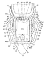
図2に示すように、リアキャリア28は,前後方向に延びる左右一対の第1パイプ部材32,32と、車幅方向に延びる第2パイプ部材34とを有している。左右の第1パイプ部材32,32の後端32a,32aが第2パイプ部材34に接合され、これら第1パイプ部材32,32および第2パイプ部材34により、上方を向いた開口35が形成されている。
As shown in FIG. 2, the
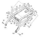
各第1パイプ部材32は、図1に示すように、後方に向かって斜め上方に大きく傾斜した前半部と、水平ないし若干後方の上方に傾斜した後半部とを含む。図2に示す第1パイプ部材32の前半部は、前方に向かって車幅方向外側に湾曲しながら延びており、図3に示すように、その前端に、第1取付部32bが設けられている。第1取付部32bに車幅方向外側からボルト30が挿通され、リヤフレーム2に設けたねじ孔(図示せず)に締結される。
As shown in FIG. 1, each
リアキャリア28は、さらに、左右の第1パイプ部材32の前後方向中間部32cを連結する第1補強パイプ部材38と、左右の第1パイプ部材32,32の前後方向中間部32cと第2パイプ部材34の両端部とを接続する左右一対の外側パイプ部材40,40とを有している。左右の外側パイプ部材40,40は、左右の第1パイプ部材32,32の車幅方向外側に位置している。本実施形態では、第1補強パイプ部材38および外側パイプ部材40は、近接する位置(前後方向中間部32c)で第1パイプ部材32に接合されているが、離れていてもよい。
The
第1パイプ部材32の前半部と後半部は、図1に示す第2補強パイプ部材42により連結されている。第2補強パイプ部材42は、第1パイプ部材32の前半部から後方に延びた後、上方に湾曲して第1パイプ部材32の後半部の下面に接合されている。第2補強パイプ部材42の前端は、第1パイプ部材32における前後方向中間部32cよりも前側に接合されている。図3に示す第2補強パイプ部材42の下面に、第2取付部42aが設けられている。第2取付部42aに車幅方向外側からボルト30が挿通され、リヤフレーム2に設けたねじ孔(図示せず)に締結される。
The front half and the rear half of the
第1パイプ部材32の後半部と外側パイプ部材40は、第3補強パイプ部材45により連結されている。第3補強パイプ45は、第1パイプ部材32の後半部から後方に向かって外側に傾斜して延びている。
The rear half of the
第1パイプ部材32の後半部および第2パイプ部材34の上面により、積載面S1が構成されている。本実施形態では、さらに、外側パイプ部材40の上面も積載面S1を構成している。これにより、積載面S1の幅を稼ぐことができる。本実施形態では、第2パイプ部材34と外側パイプ部材40は単一のパイプで構成されているが、別体に形成して連結してもよい。また、外側パイプ部材40はなくてもよい。本実施形態では、各パイプ部材32,34,38,40,42,45の接合は、溶接により実現されている。また、各パイプ部材32,34,38,40,42,45は、円筒パイプにより形成されている。リアキャリア28の構造は、本実施形態のものに限定されない。
The latter half of the
図3のリアキャリア28に、収納ボックス46が取り付けられている。収納ボックス46は、リアキャリア28の積載面S1よりも下方に配置されている。つまり、図1に示す収納ボックス46の上面46aは、積載面S1よりも下方に位置している。収納ボックス46の下面46bとリアカウル21の上面は上下方向に近接している。
A
本実施形態の収納ボックス46は、車載装置の一種であるETC車載器25を収納するケースである。ただし、収納ボックス46は、これに限定されず、例えば、工具(車載装置)を収納する工具箱、U字ロック(車載装置)を収納するケース、小物入れ等であってもよい。
The
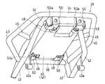
収納ボックス46は、ボルトのような締結部材48(図5)によりリアキャリア28に着脱自在に支持されている。詳細には、収納ボックス46は、ステー50を介してリアキャリア28に締結されている。図4に示すように、本実施形態では、ステー50は、4つ設けられ、リアキャリア28に溶接で取り付けられている。各ステー50の下面に、溶接ナット50aが固着されている。収納ボックス46の底面における締結部材48(図5)が締結される部位は、上方に凹んでいる。これにより、締結部材48とリアカウル21(図1)との干渉を防ぐことができる。
The
図5に示すように、収納ボックス46は、ETC車載器25が収納されるケース本体52と、ケース本体52の上方開口を開閉する蓋体54とを有している。蓋体54は、ケース本体52の前端部に設けられたヒンジ56を介して、ケース本体52に取り付けられている。
As shown in FIG. 5, the
ケース本体52の内部に、締結部材48が挿通される挿通孔55が形成されている。つまり、締結部材48が上方からケース本体52の挿通孔55に挿通され、ステー50の溶接ナット50aに締め付けられている。これにより、ケース本体52が、リアキャリア28に締結されている。ただし、締結部材48は、ケース本体52の内部ではなく、外部に配置されて、収納ボックス46の外方から収納ボックス46をリアキャリア28に締結してもよい。
An
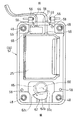
ETC車載器25は、ETCカード(精算器)が内蔵されており、ケース本体52の内面に、両面テープのような接着手段により取り付けられている。図6に示すように、本実施形態では、ETC車載器25は完全防水仕様であり、収納ボックスのケース本体52の4隅に水抜き孔58が設けられている。車載装置(本実施形態では、ETC車載器25)が完全防水でない場合、収納ボックス46を完全防水構造としてもよい。
The ETC vehicle-mounted
図2から分かるように、収納ボックス46の左右両側に、前後方向に延びる第1パイプ部材32,32が配置され、収納ボックス46の後側に、車幅方向に延びる第2パイプ部材34が配置されている。つまり、収納ボックス46は、平面視で、開口35から露出している。収納ボックス46の前側に、車幅方向に延びる第1補強パイプ部材38が配置されている。本実施形態では、収納ボックス46の上面は、第1補強パイプ部材38の上面よりも上方に位置している。
As can be seen from FIG. 2,
換言すれば、収納ボックス46の上方に、積載面S1の上側から締結部材48にアクセスして収納ボックス46が着脱可能なアクセス空間SPが形成されている。本実施形態では、アクセス空間SPからETC車載器25にもアクセス可能である。
In other words, an access space SP is formed above the
図5に示すように、ケース本体52における内部の後端部に、係合部62が設けられている。係合部62は、ケース本体52の底面から立ち上がる立壁62aと、立壁62aに連なる天井壁62bとを有し、前方に開口部62cが形成されている。立壁62aと天井壁62bとで、後述の係止片65が進入する進入空間が形成され、係止片65は開口部62cから進入空間に出し入れされる。
As shown in FIG. 5, an engaging
蓋体54は、施錠可能に構成されている。蓋体54の施錠は、例えば、キーロック式である。詳細には、蓋体54の裏面(内面)にキーロック装置60が取り付けられている。キーロック装置60は、キーの差込み口60aを有し、差込み口60aが蓋体54の上面に露出している。本実施形態では、差込み口60aは、開閉自在なゴムカバー64により覆われている。これにより、差込み口60aに泥がかかるのを防ぐことができる。差込み口60aにキーを差し込み、回動操作することでロック状態と解除状態とを切り替えることができる。
The
キーロック装置60は、キーの回動操作に連動して回動する前記係止片65を有している。係止片65は、ロック状態では、係合部62の進入空間内に進入している。この状態では、係止片65が係合部62の天井壁62bに当接するので、蓋体54を開くことができない。解除状態では、係止片65は、係合部62の進入空間から退出している。この状態では、蓋体54を開くことが可能である。図6では、解除状態の係止片65を示している。
The
ETC車載器25の前面に、配線(ケーブル)66が接続されている。配線66は、コネクタ68(図6)を介してETC車載器25の前面に接続されている。配線66は、ETC車載器25と車体前側のETCアンテナ26(図1)とを接続する。収納ボックス46の前端、詳細には、ケース本体52の前壁に、配線取出し口69が設けられている。
A wiring (cable) 66 is connected to the front surface of the ETC vehicle-mounted
本実施形態の配線取出し口69には、ゴムのような弾性体からなる封止材71が、ケース本体52の前壁に対して着脱自在に取り付けられている。配線取出し口69に、配線66が挿入される貫通孔69aが形成されている。配線66を挿入し易いように、貫通孔69aに連接してスリットを設けてもよい。
A sealing
収納ボックス46へのETC車載器25の設置は、以下の手順で行われる。配線66をETC車載器25にコネクタ接続した状態で、ETC車載器25をケース本体52に取り付けるとともに、封止材71をケース本体52の配線取出し口69に係合する。これにより、ETC車載器25が収納ボックス46に設置される。あるいは、ETC車載器25をケース本体52に取り付けた後で、配線66をETC車載器25にコネクタ接続し、封止材71を配線取出し口69に係合してもよい。
The installation of the ETC vehicle-mounted
つぎに、アクセス空間SPから収納ボックス46、ETC車載器25等へのアクセス手順を説明する。まず、図2のゴムカバー64を開けて、キーロック装置60の差込み口60にキー(図示せず)を差し込んで、矢印AR1の方向に回動させる。これにより、図6に二点鎖線で示すように、キーロック装置60の係止片65が係合部62から外れ、ロックが解除される。
Next, an access procedure from the access space SP to the
このロック解除により、蓋体54が開閉可能となり、図5に示すように、蓋体54を開ける。蓋体54が完全に開くと、図6に示すように、リアキャリア28の開口35(図2)から上方に、ETC車載器25および締結部材48が露出した状態となる。したがって、アクセス空間SPから、ETC車載器25を収納ボックス46に対して着脱したり、締結部材48を操作して収納ボックス46を車体に対して着脱したりすることができる。
By releasing this lock, the
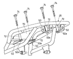
図7に示すように、リアキャリア28に、収納ボックス46に代えて、荷物が積載される積載用のプレート70を取り付けることができる。つまり、リアキャリア28に、収納ボックス46と積載用のプレート70が選択的に締結可能である。プレート70は、例えば、アルミニウム製の板材からなり、その上面が、前述の積載面S1と面一になる。本実施形態では、プレート70は、収納ボックス46と共通のステー50に、つぎのようにして選択的に締結される。
As shown in FIG. 7, instead of the
図8に示すように、リアキャリア28にプレート70を締結する際は、筒状のカラー72を介して長尺のボルト74を用いる。詳細には、プレート70の下面とステー50の上面との間にカラー72を介在させる。この状態で、ボルト74が、上方からカラー72の中空部に挿通され、ステー50の溶接ナット50aに締め付けられる。これにより、リアキャリア28に、プレート70が着脱自在に取り付けられる。ボルト74の頭部は、図7の積載面S1よりも上方に突出しないように設定されている。
As shown in FIG. 8, when fastening the
上記構成によれば、図2に示すアクセス空間SPを介して、上方から収納ボックス46を着脱可能できる。つまり、リアキャリア28を車体から取り外さなくても、収納ボックス46にアクセスできる。したがって、収納ボックス46へのアクセス性がよい。
According to the above configuration, the
また、収納ボックス46内に収納されたETC車載器25にも、アクセス空間SPからアクセス可能である。したがって、リアキャリア28を取り外さなくても、ETC車載器25の取り付け、取り外しが可能であり、作業性およびメンテナンス性がよい。
Further, the ETC vehicle-mounted
図5に示す締結部材48が収納ボックス46のケース本体52の内部に位置し、アクセス空間SPを介して上方から締結部材48を操作することにより、収納ボックス46がリアキャリア28に締結されている。これにより、締結部材48が外部に露出しないので、外観がよい。
The
また、蓋体54が施錠可能に構成されている。つまり、蓋体54のロックを解除して蓋体54を開けないと、ETC車載器25および締結部材48にアクセスできない。したがって、キーを持っていないと、ETC車載器25のケース本体52からの取り外しや、収納ボックス46の車体からの取り外しが困難である。これにより、盗難防止性が向上する。
Further, the
蓋体54は、ケース本体52の前端部に設けられたヒンジ56を介して、ケース本体52に取り付けられている。これにより、走行時に、走行風により蓋体54が閉まる方向に力が働くので、蓋体54の閉止、ロックを忘れた場合でも、蓋体54が開きにくい。
The
また、ETCのアンテナ26(図1)が車両の前側に配置され、ETC車載器25の配線取出し口69が収納ボックス46の前端に設けられている。これにより、ETC車載器25とアンテナ26との間の配線66を短くでき、配線作業も容易である。
Further, the ETC antenna 26 (FIG. 1) is arranged on the front side of the vehicle, and the
図3に示す収納ボックス46の左右両側に、前後方向に延びる第1パイプ部材32,32が配置され、収納ボックス46の後側に、車幅方向に延びる第2パイプ部材34が配置されている。これら第1および第2パイプ部材32,34により、収納ボックス46が保護される。
リアキャリア28のステー50に、収納ボックス46と図7の積載用のプレート70が選択的に締結可能である。詳細には、図4に示す収納ボックス46を取り付けるためのステー50と、プレート70を取り付けるための図8に示すステー50が共通化されている。これにより、車体側(リアキャリア28)を変更することなく、収納ボックス搭載タイプと積載用のプレート搭載タイプの切換えができる。
The
本発明は、以上の実施形態に限定されるものでなく、本発明の要旨を逸脱しない範囲内で、種々の追加、変更または削除が可能である。例えば、上記実施形態では、自動二輪車について説明したが、本発明の収納ボックスの取付構造は、自動二輪車以外の鞍乗型車両、例えば、三輪車、四輪バギー等にも適用できる。したがって、そのようなものも本発明の範囲内に含まれる。 The present invention is not limited to the above embodiments, and various additions, changes or deletions can be made without departing from the scope of the present invention. For example, although the motorcycle has been described in the above embodiment, the storage box mounting structure of the present invention can be applied to a straddle-type vehicle other than the motorcycle, such as a three-wheeled vehicle or a four-wheeled buggy. Therefore, such is also included in the scope of the present invention.
20 シート
25 ETC車載器(車載装置)
26 ETCのアンテナ
28 リアキャリア
32 第1パイプ部材
34 第2パイプ部材
46 収納ボックス
48 締結部材
50 ステー
52 ケース本体
54 蓋体
55 挿通孔
56 ヒンジ
69 配線取出し口
70 プレート
S1 積載面
SP アクセス空間
20
26
Claims (9)
前記リアキャリアの積載面よりも下方に、前記収納ボックスが配置され、
前記収納ボックスは、締結部材により前記リアキャリアに着脱自在に支持され、
前記収納ボックスの上方に、前記積載面の上側から前記締結部材にアクセスして前記収納ボックスが着脱可能なアクセス空間が形成されている収納ボックスの取付構造。 A storage box mounting structure for mounting a storage box on a rear carrier behind a seat of a saddle type vehicle,
The storage box is arranged below the loading surface of the rear carrier,
The storage box is detachably supported by the rear carrier by a fastening member,
A storage box mounting structure in which an access space is formed above the storage box so that the fastening member can be accessed from the upper side of the stacking surface and the storage box can be detached.
前記車載装置は、前記アクセス空間からアクセス可能に構成されている収納ボックスの取付構造。 The mounting structure for a storage box according to claim 1, wherein an in-vehicle device is stored in the storage box,
The in-vehicle device is a storage box mounting structure configured to be accessible from the access space.
前記ケース本体の内部に、前記締結部材が挿通される挿通孔が形成され、
前記ケース本体が、上方からの前記締結部材により前記リアキャリアに締結されている収納ボックスの取付構造。 The storage box mounting structure according to claim 2, wherein the storage box has a case main body in which the vehicle-mounted device is stored, and a lid body that opens and closes an upper opening of the case main body.
An insertion hole, through which the fastening member is inserted, is formed inside the case body,
A storage box mounting structure in which the case body is fastened to the rear carrier by the fastening member from above.
前記ETC車載器の配線取出し口が、前記収納ボックスの前端に設けられている収納ボックスの取付構造。 The storage box mounting structure according to claim 6, wherein the ETC antenna is arranged on the front side of the vehicle,
The storage box mounting structure in which the wiring outlet of the ETC vehicle-mounted device is provided at the front end of the storage box.
前記リアキャリアの前記ステーには、前記収納ボックスと積載用のプレートが選択的に締結可能である収納ボックスの取付構造。 The storage box mounting structure according to any one of claims 1 to 7, wherein the storage box is fastened to the rear carrier via a stay,
A storage box mounting structure in which the storage box and a loading plate can be selectively fastened to the stay of the rear carrier.
前記収納ボックスの左右両側に、前後方向に延びる第1パイプ部材が配置され、
前記収納ボックスの後側に、車幅方向に延びる第2パイプ部材が配置されている収納ボックスの取付構造。
The mounting structure for a storage box according to claim 1, wherein the rear carrier is composed of a plurality of pipe members,
First pipe members extending in the front-rear direction are arranged on both left and right sides of the storage box,
A storage box mounting structure in which a second pipe member extending in the vehicle width direction is arranged on the rear side of the storage box.
Priority Applications (1)
| Application Number | Priority Date | Filing Date | Title |
|---|---|---|---|
| JP2018219261A JP7186585B2 (en) | 2018-11-22 | 2018-11-22 | Mounting structure of storage box for straddle-type vehicle |
Applications Claiming Priority (1)
| Application Number | Priority Date | Filing Date | Title |
|---|---|---|---|
| JP2018219261A JP7186585B2 (en) | 2018-11-22 | 2018-11-22 | Mounting structure of storage box for straddle-type vehicle |
Publications (2)
| Publication Number | Publication Date |
|---|---|
| JP2020082995A true JP2020082995A (en) | 2020-06-04 |
| JP7186585B2 JP7186585B2 (en) | 2022-12-09 |
Family
ID=70909566
Family Applications (1)
| Application Number | Title | Priority Date | Filing Date |
|---|---|---|---|
| JP2018219261A Active JP7186585B2 (en) | 2018-11-22 | 2018-11-22 | Mounting structure of storage box for straddle-type vehicle |
Country Status (1)
| Country | Link |
|---|---|
| JP (1) | JP7186585B2 (en) |
Cited By (1)
| Publication number | Priority date | Publication date | Assignee | Title |
|---|---|---|---|---|
| JP2025509143A (en) * | 2022-03-14 | 2025-04-11 | ヤマハ発動機株式会社 | Saddle-type vehicle |
Citations (3)
| Publication number | Priority date | Publication date | Assignee | Title |
|---|---|---|---|---|
| JPS4713859U (en) * | 1971-03-19 | 1972-10-18 | ||
| JPS5489758U (en) * | 1977-12-07 | 1979-06-25 | ||
| JP2008074290A (en) * | 2006-09-22 | 2008-04-03 | Honda Motor Co Ltd | Mounting structure for vehicle communication device |
-
2018
- 2018-11-22 JP JP2018219261A patent/JP7186585B2/en active Active
Patent Citations (3)
| Publication number | Priority date | Publication date | Assignee | Title |
|---|---|---|---|---|
| JPS4713859U (en) * | 1971-03-19 | 1972-10-18 | ||
| JPS5489758U (en) * | 1977-12-07 | 1979-06-25 | ||
| JP2008074290A (en) * | 2006-09-22 | 2008-04-03 | Honda Motor Co Ltd | Mounting structure for vehicle communication device |
Cited By (2)
| Publication number | Priority date | Publication date | Assignee | Title |
|---|---|---|---|---|
| JP2025509143A (en) * | 2022-03-14 | 2025-04-11 | ヤマハ発動機株式会社 | Saddle-type vehicle |
| JP7826506B2 (en) | 2022-03-14 | 2026-03-09 | ヤマハ発動機株式会社 | Saddle-type vehicle |
Also Published As
| Publication number | Publication date |
|---|---|
| JP7186585B2 (en) | 2022-12-09 |
Similar Documents
| Publication | Publication Date | Title |
|---|---|---|
| JP4252876B2 (en) | Motorcycle | |
| JP4332010B2 (en) | Scooter-type vehicle article storage structure | |
| JP4381768B2 (en) | Motorcycle storage equipment | |
| JP4176610B2 (en) | Scooter type vehicle | |
| US6497300B2 (en) | Locking arrangement for motorcycle | |
| JP4119344B2 (en) | Motorcycle | |
| JP4364341B2 (en) | Article storage device for motorcycle | |
| EP2447139B1 (en) | Motorcycle | |
| JP4243162B2 (en) | non-motorized vehicle | |
| EP2003045B1 (en) | Motorcycle | |
| CN104870302A (en) | Saddled Vehicle | |
| JP4176609B2 (en) | non-motorized vehicle | |
| JP7186585B2 (en) | Mounting structure of storage box for straddle-type vehicle | |
| US7735892B2 (en) | Front portion structure of vehicle | |
| JPH0826160A (en) | Rear body structure of motorcycle | |
| JPH08207849A (en) | Seat rail structure for scooter type vehicle | |
| CN100408414C (en) | steering lock device | |
| JP4153803B2 (en) | Motorcycle fuel tank arrangement | |
| JP4145766B2 (en) | Scooter type vehicle | |
| JP4734205B2 (en) | Mounting structure for vehicle communication device | |
| JPH08318883A (en) | Anti-theft device for small vehicles | |
| JP3464748B2 (en) | Dust proof structure for seat opening and closing type vehicles | |
| JP3821885B2 (en) | Scooter type motorcycle | |
| JP4414189B2 (en) | Motorcycle | |
| JP2925448B2 (en) | Stand device for automatic two- and three-wheeled vehicles |
Legal Events
| Date | Code | Title | Description |
|---|---|---|---|
| A621 | Written request for application examination |
Free format text: JAPANESE INTERMEDIATE CODE: A621 Effective date: 20210609 |
|
| A711 | Notification of change in applicant |
Free format text: JAPANESE INTERMEDIATE CODE: A712 Effective date: 20220124 |
|
| A977 | Report on retrieval |
Free format text: JAPANESE INTERMEDIATE CODE: A971007 Effective date: 20220422 |
|
| A131 | Notification of reasons for refusal |
Free format text: JAPANESE INTERMEDIATE CODE: A131 Effective date: 20220510 |
|
| A521 | Request for written amendment filed |
Free format text: JAPANESE INTERMEDIATE CODE: A523 Effective date: 20220705 |
|
| A131 | Notification of reasons for refusal |
Free format text: JAPANESE INTERMEDIATE CODE: A131 Effective date: 20220816 |
|
| A521 | Request for written amendment filed |
Free format text: JAPANESE INTERMEDIATE CODE: A523 Effective date: 20220930 |
|
| TRDD | Decision of grant or rejection written | ||
| A01 | Written decision to grant a patent or to grant a registration (utility model) |
Free format text: JAPANESE INTERMEDIATE CODE: A01 Effective date: 20221101 |
|
| A61 | First payment of annual fees (during grant procedure) |
Free format text: JAPANESE INTERMEDIATE CODE: A61 Effective date: 20221129 |
|
| R150 | Certificate of patent or registration of utility model |
Ref document number: 7186585 Country of ref document: JP Free format text: JAPANESE INTERMEDIATE CODE: R150 |
|
| R250 | Receipt of annual fees |
Free format text: JAPANESE INTERMEDIATE CODE: R250 |