JP2020095960A - Multilayer structure and aircraft component - Google Patents
Multilayer structure and aircraft component Download PDFInfo
- Publication number
- JP2020095960A JP2020095960A JP2019222605A JP2019222605A JP2020095960A JP 2020095960 A JP2020095960 A JP 2020095960A JP 2019222605 A JP2019222605 A JP 2019222605A JP 2019222605 A JP2019222605 A JP 2019222605A JP 2020095960 A JP2020095960 A JP 2020095960A
- Authority
- JP
- Japan
- Prior art keywords
- heater
- layer
- multilayer structure
- heater layer
- structure according
- Prior art date
- Legal status (The legal status is an assumption and is not a legal conclusion. Google has not performed a legal analysis and makes no representation as to the accuracy of the status listed.)
- Pending
Links
Images



Classifications
-
- B—PERFORMING OPERATIONS; TRANSPORTING
- B64—AIRCRAFT; AVIATION; COSMONAUTICS
- B64D—EQUIPMENT FOR FITTING IN OR TO AIRCRAFT; FLIGHT SUITS; PARACHUTES; ARRANGEMENT OR MOUNTING OF POWER PLANTS OR PROPULSION TRANSMISSIONS IN AIRCRAFT
- B64D15/00—De-icing or preventing icing on exterior surfaces of aircraft
- B64D15/12—De-icing or preventing icing on exterior surfaces of aircraft by electric heating
-
- H—ELECTRICITY
- H05—ELECTRIC TECHNIQUES NOT OTHERWISE PROVIDED FOR
- H05B—ELECTRIC HEATING; ELECTRIC LIGHT SOURCES NOT OTHERWISE PROVIDED FOR; CIRCUIT ARRANGEMENTS FOR ELECTRIC LIGHT SOURCES, IN GENERAL
- H05B3/00—Ohmic-resistance heating
- H05B3/02—Details
- H05B3/06—Heater elements structurally combined with coupling elements or holders
-
- H—ELECTRICITY
- H05—ELECTRIC TECHNIQUES NOT OTHERWISE PROVIDED FOR
- H05B—ELECTRIC HEATING; ELECTRIC LIGHT SOURCES NOT OTHERWISE PROVIDED FOR; CIRCUIT ARRANGEMENTS FOR ELECTRIC LIGHT SOURCES, IN GENERAL
- H05B3/00—Ohmic-resistance heating
- H05B3/10—Heating elements characterised by the composition or nature of the materials or by the arrangement of the conductor
- H05B3/12—Heating elements characterised by the composition or nature of the materials or by the arrangement of the conductor characterised by the composition or nature of the conductive material
- H05B3/14—Heating elements characterised by the composition or nature of the materials or by the arrangement of the conductor characterised by the composition or nature of the conductive material the material being non-metallic
- H05B3/145—Carbon only, e.g. carbon black, graphite
-
- H—ELECTRICITY
- H05—ELECTRIC TECHNIQUES NOT OTHERWISE PROVIDED FOR
- H05B—ELECTRIC HEATING; ELECTRIC LIGHT SOURCES NOT OTHERWISE PROVIDED FOR; CIRCUIT ARRANGEMENTS FOR ELECTRIC LIGHT SOURCES, IN GENERAL
- H05B3/00—Ohmic-resistance heating
- H05B3/10—Heating elements characterised by the composition or nature of the materials or by the arrangement of the conductor
- H05B3/12—Heating elements characterised by the composition or nature of the materials or by the arrangement of the conductor characterised by the composition or nature of the conductive material
- H05B3/14—Heating elements characterised by the composition or nature of the materials or by the arrangement of the conductor characterised by the composition or nature of the conductive material the material being non-metallic
- H05B3/146—Conductive polymers, e.g. polyethylene, thermoplastics
-
- H—ELECTRICITY
- H05—ELECTRIC TECHNIQUES NOT OTHERWISE PROVIDED FOR
- H05B—ELECTRIC HEATING; ELECTRIC LIGHT SOURCES NOT OTHERWISE PROVIDED FOR; CIRCUIT ARRANGEMENTS FOR ELECTRIC LIGHT SOURCES, IN GENERAL
- H05B3/00—Ohmic-resistance heating
- H05B3/20—Heating elements having extended surface area substantially in a two-dimensional [2D] plane, e.g. plate-heater
- H05B3/22—Heating elements having extended surface area substantially in a two-dimensional [2D] plane, e.g. plate-heater non-flexible
- H05B3/26—Heating elements having extended surface area substantially in a two-dimensional [2D] plane, e.g. plate-heater non-flexible heating conductor mounted on insulating base
- H05B3/265—Heating elements having extended surface area substantially in a two-dimensional [2D] plane, e.g. plate-heater non-flexible heating conductor mounted on insulating base the insulating base being an inorganic material, e.g. ceramic
-
- H—ELECTRICITY
- H05—ELECTRIC TECHNIQUES NOT OTHERWISE PROVIDED FOR
- H05B—ELECTRIC HEATING; ELECTRIC LIGHT SOURCES NOT OTHERWISE PROVIDED FOR; CIRCUIT ARRANGEMENTS FOR ELECTRIC LIGHT SOURCES, IN GENERAL
- H05B2203/00—Aspects relating to Ohmic resistive heating covered by group H05B3/00
- H05B2203/009—Heaters using conductive material in contact with opposing surfaces of the resistive element or resistive layer
- H05B2203/01—Heaters comprising a particular structure with multiple layers
-
- H—ELECTRICITY
- H05—ELECTRIC TECHNIQUES NOT OTHERWISE PROVIDED FOR
- H05B—ELECTRIC HEATING; ELECTRIC LIGHT SOURCES NOT OTHERWISE PROVIDED FOR; CIRCUIT ARRANGEMENTS FOR ELECTRIC LIGHT SOURCES, IN GENERAL
- H05B2203/00—Aspects relating to Ohmic resistive heating covered by group H05B3/00
- H05B2203/019—Heaters using heating elements having a negative temperature coefficient
-
- H—ELECTRICITY
- H05—ELECTRIC TECHNIQUES NOT OTHERWISE PROVIDED FOR
- H05B—ELECTRIC HEATING; ELECTRIC LIGHT SOURCES NOT OTHERWISE PROVIDED FOR; CIRCUIT ARRANGEMENTS FOR ELECTRIC LIGHT SOURCES, IN GENERAL
- H05B2203/00—Aspects relating to Ohmic resistive heating covered by group H05B3/00
- H05B2203/02—Heaters using heating elements having a positive temperature coefficient
-
- H—ELECTRICITY
- H05—ELECTRIC TECHNIQUES NOT OTHERWISE PROVIDED FOR
- H05B—ELECTRIC HEATING; ELECTRIC LIGHT SOURCES NOT OTHERWISE PROVIDED FOR; CIRCUIT ARRANGEMENTS FOR ELECTRIC LIGHT SOURCES, IN GENERAL
- H05B2214/00—Aspects relating to resistive heating, induction heating and heating using microwaves, covered by groups H05B3/00, H05B6/00
- H05B2214/02—Heaters specially designed for de-icing or protection against icing
-
- H—ELECTRICITY
- H05—ELECTRIC TECHNIQUES NOT OTHERWISE PROVIDED FOR
- H05B—ELECTRIC HEATING; ELECTRIC LIGHT SOURCES NOT OTHERWISE PROVIDED FOR; CIRCUIT ARRANGEMENTS FOR ELECTRIC LIGHT SOURCES, IN GENERAL
- H05B2214/00—Aspects relating to resistive heating, induction heating and heating using microwaves, covered by groups H05B3/00, H05B6/00
- H05B2214/04—Heating means manufactured by using nanotechnology
Landscapes
- Engineering & Computer Science (AREA)
- Aviation & Aerospace Engineering (AREA)
- Chemical & Material Sciences (AREA)
- Ceramic Engineering (AREA)
- Resistance Heating (AREA)
- Surface Heating Bodies (AREA)
- Laminated Bodies (AREA)
Abstract
Description
例示的実施形態は、カーボンナノチューブヒータの技術に関し、より具体的には、航空機で使用されるカーボンナノチューブヒータを備える多層構造に関する。 Example embodiments relate to the technology of carbon nanotube heaters, and more particularly to multi-layer structures with carbon nanotube heaters used in aircraft.
航空機は、着氷を防止する航空機の羽根の電熱加熱技術を使用する。カーボンナノチューブ(CNT)ヒータは、そのヒータが高い強度対重量比、及び高電力密度を有するため、航空機応用に対して有望な選択である。例えば、CNTヒータは、カーボンナノチューブ及びシリコーンの合成物を含み得る。しかしながら、高温において、カーボンナノチューブヒータの電熱抵抗は、著しく減少し(負の温度係数)、過度の電力出力及び羽根の過熱をもたらす。 Aircraft use electrothermal heating technology for aircraft vanes to prevent icing. Carbon nanotube (CNT) heaters are a promising choice for aircraft applications because of their high strength to weight ratio and high power density. For example, a CNT heater can include a composite of carbon nanotubes and silicone. However, at high temperatures, the electrothermal resistance of carbon nanotube heaters is significantly reduced (negative temperature coefficient), leading to excessive power output and blade overheating.
加えて、羽根除氷システムは、多くの場合、複数の温度センサを使用して、羽根表面温度を監視及び制御する。しかしながら、温度センサは、単一の局所的位置での温度だけを監視することができる。さらに、羽根の表面全体にわたって、温度センサを設置することは実現が難しい。温度が羽根の表面にわたって高温点及び低温点で変化し得るため、斯かるシステムで羽根温度を監視または制御することが困難な状態になる。次に、この温度変化は、本システムの過熱及び故障をもたらす可能性がある。 In addition, blade deicing systems often use multiple temperature sensors to monitor and control blade surface temperature. However, the temperature sensor can only monitor the temperature at a single local location. Furthermore, it is difficult to implement the temperature sensor over the entire surface of the blade. The temperature can change at hot and cold points across the surface of the vane, making it difficult to monitor or control the vane temperature in such systems. This temperature change can then lead to overheating and failure of the system.
したがって、電力出力効率を改善し、羽根表面全体にわたって温度を調整し、過熱を防止することができる航空機用のCNTヒータを有する頑丈かつ軽量の構造を開発する必要がある。 Therefore, there is a need to develop a sturdy and lightweight structure with aircraft CNT heaters that can improve power output efficiency, regulate temperature across the blade surface and prevent overheating.
CNTヒータを備える第1のヒータ層であって、当該CNTヒータはカーボンナノチューブとシリコーンとの合成物を含む、当該第1のヒータ層と、PTCヒータを備える第2のヒータ層であって、当該PTCヒータはカーボンブラックとポリマーとの合成物を含む、当該第2のヒータ層と、を備える、多層構造が開示され、第1のヒータ層及び第2のヒータ層は、各々、第1及び第2のヒータ層に対して電気的に直列であり、第1のヒータ層は電気抵抗率に対して負の温度係数を有し、第2のヒータ層は電気抵抗率に対して正の温度係数を有する。 A first heater layer including a CNT heater, wherein the CNT heater includes a first heater layer containing a composite of carbon nanotubes and silicone, and a second heater layer including a PTC heater. A PTC heater is disclosed having a second heater layer comprising a composite of carbon black and a polymer, wherein the first heater layer and the second heater layer are respectively a first and a second heater layer. Electrically in series with two heater layers, the first heater layer having a negative temperature coefficient of electrical resistivity and the second heater layer having a positive temperature coefficient of electrical resistivity. Have.
また、多層構造を含む航空機コンポーネントが開示される。 Also disclosed is an aircraft component that includes a multi-layer structure.
以下の説明は、任意の方法において限定的であると考慮されるべきではない。付随の図面を参照すると、同様の要素は、同様に番号が付けられている。 The following description should not be considered limiting in any way. With reference to the accompanying drawings, similar elements are similarly numbered.
開示された装置及び方法の1つ以上の実施形態の詳細な説明は、例示によって本明細書に提示され、図を参照して限定されるものではない。 A detailed description of one or more embodiments of the disclosed apparatus and method is presented herein by way of illustration and not limitation with reference to the figures.
図1を参照すると、多層構造10は、金属層12、接着層22、ガラス繊維層14、第1のヒータ層16、及び第2のヒータ層18を含む。多層構造10は、図1に示されるものよりも、多い層または少ない層を含み得る。例えば、多層構造10は、追加の接着層22及び追加のガラス繊維層14を含み得る。多層構造10は、図1に示されるものと同じ順序で配列される層を含み得る。代替として、多層構造10は、図1に示されるものと異なる順序で配列される層を含み得る。例えば、図1に示されるように、金属層12は、第2のヒータ層18よりも第1のヒータ層16の近くに位置し得る。代替として、金属層12は、第1のヒータ層16よりも第2のヒータ層18の近くに位置し得る(例えば、図1に示されるような第1のヒータ層16及び第2のヒータ層18の位置を交換することができる)。
Referring to FIG. 1, the
図4を参照すると、第1のヒータ層16及び第2のヒータ層18は、各々、第1のヒータ層16及び第2のヒータ層18に対して電気的に直列であり得る。「V」は電圧源を示す。言い換えれば、最初に、電流は第1のヒータ層16を通過することができ、その後、続いて、電流は、第2のヒータ層18を通過することができる。
Referring to FIG. 4, the
第1のヒータ層16は、電気抵抗率に対して負の温度係数を有し得る。言い換えれば、第1のヒータ層16の温度が増加するにつれて、第1のヒータ層16の電気伝導度が増加する(すなわち、電気抵抗が減少する)。第2のヒータ層18は、電気抵抗率に対して正の温度係数を有し得る。言い換えれば、第2のヒータ層18の温度が増加するにつれて、第2のヒータ層18の電気抵抗が増加する(すなわち、電気伝導度が減少する)。
The
電流が第1のヒータ層16を通過するとき、第1のヒータ層16の温度が増加し、ひいては、第1のヒータ層16の電気抵抗が減少する。これは、第1のヒータ層16からの熱散逸の増加をもたらす。次に、電流が第2のヒータ層18(電気的な直列において隣にある)を通過し、第2のヒータ層18の温度を増加させ、ひいては、第2のヒータ層18の電気抵抗が増加する。したがって、高温において、第1のヒータ層16から来る電流は、続いて第2のヒータ層18を通過するときに抑制されるだろう。従って、第1のヒータ層16及び第2のヒータ層18は、自己調整関係を有するだろう。従って、第1のヒータ層16及び第2のヒータ層18は、多層構造10の温度を均衡及び安定させるだろう。これは、多層構造10の熱出力のための自己調整ループを作る。例えば、第1のヒータ層16から出力された温度及び電力出力が過度である場合、第2のヒータ層18(抵抗が増加した)は、ループ内の電流を抑制することによって補正され、それによって、第1のヒータ層16への電力が減るであろう。この補正効果は、自己調整システムをもたらす。したがって、多層構造は、局所的な高温点及び低温点に対処し、航空機の羽根の表面にわたって一様な温度プロフィールを維持することができる。多層構造10は、電力出力効率を改善し、羽根表面全体にわたって温度を調整し、過熱を防止することができる航空機用の頑丈かつ軽量のヒータ構造である。
When an electric current passes through the
第1のヒータ層16は、カーボンナノチューブ(CNT)ヒータを備え得る。例えば、CNTヒータは、カーボンナノチューブとシリコーンとの合成物を含み得る。
The
第2のヒータ層18は、正の温度係数(positive temperature coefficient,PTC)ヒータを備え得る。例えば、PTCヒータは、カーボンブラックとポリマーとの合成物を含み得る。
The
所与の温度に対して、合成物の電気抵抗は、その組成を変化させることによって変化し得ることが当技術分野で理解されている。例えば、第1のヒータ層16のカーボンナノチューブの割合を増加させるにつれて、電気抵抗は、所与の温度に対して減少する(K.Chu、D.Kim、Y.Sohn、S.Lee、C.Moon、及びS.Park、「Electrical and thermal properties of carbon−nanotube composite for flexible electric heating−unit applications」IEEE Electron Device Lett.、vol.34、no.5、pp.668〜670、2013年5月)。同様に、第2のヒータ層18のカーボンブラックの割合を増加させるにつれて、電気抵抗は、所与の温度に対して減少する(K.Chu、D.−J.Yun、D.Kim、H.Park、及びS.−H.Park、「Study of electric heating effects on carbon nanotube polymer composites」、Organic Electron.、vol.15、no.11、pp.2734〜2741,2014年11月)。したがって、第1のヒータ層16及び第2のヒータ層18の電気抵抗は、いずれかの所与の適用のために当業者によって、必要に応じて、変化し得ることが理解されている。
It is understood in the art that, for a given temperature, the electrical resistance of a composition can be changed by changing its composition. For example, as the proportion of carbon nanotubes in the
多層構造10は、さらに、接着層22(例えば、2つ以上の接着層22)を含み得る。例えば、接着層22は、熱導体物質、電気絶縁体材料、または前述のうちの少なくとも1つを含む組み合わせを含み得る。接着層22は、隣接層を一緒に接合することができる。
The
多層構造10は、さらに、ガラス繊維層14(例えば、2つ以上のガラス繊維層14)を含み得る。
The
多層構造10は、さらに、金属層12を含み得る。例えば、金属層12は、アルミニウム、鋼、または前述のうちの少なくとも1つを含む組み合わせを含み得る。金属層12は、多層構造10の外側表面であり得る。例えば、金属層12は、多層構造10を含む航空機コンポーネントの外側表面であり得る。例えば、航空機コンポーネントは航空機の羽根であり得る。
The
(実施例)
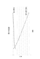
図2及び図3を参照して、変化する温度(°C)における多層ヒータ構造の特性が提示されている。R1は、図1に示されるような多層構造10の第1のヒータ層16に関する抵抗(Ω)である。R2は、図1に示されるような多層構造10の第2のヒータ層18に関する抵抗(Ω)である。R1+R2は、多層構造10の電気的な直列の合成抵抗である。R3は、比較目的のために試験された、カーボンナノチューブとシリコーンとの合成物を含む、別に独立しているCNTヒータの抵抗である。電気的な直列の合成抵抗(R1+R2)は、図2に示されるような低温においてR3以下である。図3に示されるような電力(R1+R2)は、図1に示されるような多層構造10によって散逸される電力(ワット)である。
(Example)
2 and 3, the characteristics of the multi-layer heater structure at varying temperatures (°C) are presented. R1 is the resistance (Ω) for the
図2及び図3に示されるように、高温において、多層構造10の平均電力散逸(R1+R2)は、独立しているヒータR3よりも著しく低くなる。第2のヒータ層18(R2)は、自己調整最大温度を補助し、その抵抗を増加させることによって、ひいては電流を減らすことによって、過熱を回避する。多層構造10(R1+R2)は、電力出力効率を改善し、羽根表面全体にわたって温度を調整し、過熱を防止することができる航空機用の頑丈かつ軽量のヒータ構造である。
As shown in FIGS. 2 and 3, at high temperatures, the average power dissipation (R1+R2) of the
用語「約(about)」は、出願時に利用可能である機器に基づく特定の量の測定値と関連付けられるある程度の誤差を含むことが意図される。 The term "about" is intended to include the degree of error associated with certain instrument-based measurements that are available at the time of filing.
本明細書で使用された専門用語は、特定の実施形態だけを説明する目的のためのものであり、本開示を限定することを意図していない。本明細書に使用されるような単数形「a」、「an」、及び「the」は、文脈で他に明確に示さない限り、同様に、複数形を含むことが意図される。さらに、用語「備える(comprises)」及び/または「備えている(comprising)」は、本明細書で使用されるとき、述べられた特徴、整数、ステップ、動作、要素、及び/または構成要素の存在を規定するが、1つ以上の他の特徴、整数、ステップ、動作、要素、構成要素、及び/またはそれらの群の存在または追加を除外するわけではないことが理解されるであろう。 The terminology used herein is for the purpose of describing particular embodiments only and is not intended to limit the present disclosure. As used herein, the singular forms "a", "an", and "the" are intended to include the plural forms as well, unless the context clearly indicates otherwise. Further, the terms “comprises” and/or “comprising”, as used herein, refer to the stated features, integers, steps, acts, elements, and/or components. It will be understood that the presence is defined but does not exclude the presence or addition of one or more other features, integers, steps, acts, elements, components, and/or groups thereof.
本開示では例示の一実施形態または複数の実施形態を参照して説明されているが、本開示の範囲から逸脱することなく、様々な変更がされ得、均等のものがその要素の代わりになり得ることを当業者によって理解されるだろう。加えて、特定の状況または物質を本開示の教示に、その本質的範囲から逸脱することなく適応させるために、多くの修正がされ得る。したがって、本開示は、本開示を実行するために想到される最良の形態として開示される特定の実施形態に限定されないが、本開示は、「特許請求の範囲」の範囲内にある全ての実施形態を含むことが意図される。 Although this disclosure has been described with reference to one or more exemplary embodiments, various changes may be made and equivalents may replace the elements without departing from the scope of this disclosure. It will be appreciated by those skilled in the art to obtain. In addition, many modifications may be made to adapt a particular situation or material to the teachings of this disclosure without departing from its essential scope. Therefore, this disclosure is not limited to the particular embodiments disclosed as the best mode contemplated for carrying out this disclosure, but this disclosure is intended to cover all implementations that fall within the scope of the claims. It is intended to include forms.
Claims (12)
正の温度係数(PTC)ヒータを備える第2のヒータ層であって、前記正の温度係数ヒータはカーボンブラックとポリマーとの合成物を含む、第2のヒータ層と、
を備え、
前記第1のヒータ層及び前記第2のヒータ層は、各々、電気的に直列な、第1及び第2のヒータ層であり、
前記第1のヒータ層は、電気抵抗率に対して負の温度係数を有し、
前記第2のヒータ層は、電気抵抗率に対して正の温度係数を有する、多層構造。 A first heater layer comprising a carbon nanotube (CNT) heater, the carbon nanotube heater comprising a composite of carbon nanotubes and silicone,
A second heater layer comprising a positive temperature coefficient (PTC) heater, the positive temperature coefficient heater comprising a composite of carbon black and a polymer,
Equipped with
The first heater layer and the second heater layer are electrically serial first and second heater layers, respectively.
The first heater layer has a negative temperature coefficient with respect to electrical resistivity,
The second heater layer has a multi-layer structure having a positive temperature coefficient with respect to electrical resistivity.
Applications Claiming Priority (2)
| Application Number | Priority Date | Filing Date | Title |
|---|---|---|---|
| IN201811047213 | 2018-12-13 | ||
| IN201811047213 | 2018-12-13 |
Publications (1)
| Publication Number | Publication Date |
|---|---|
| JP2020095960A true JP2020095960A (en) | 2020-06-18 |
Family
ID=68916416
Family Applications (1)
| Application Number | Title | Priority Date | Filing Date |
|---|---|---|---|
| JP2019222605A Pending JP2020095960A (en) | 2018-12-13 | 2019-12-10 | Multilayer structure and aircraft component |
Country Status (5)
| Country | Link |
|---|---|
| US (1) | US11167856B2 (en) |
| EP (1) | EP3668270B1 (en) |
| JP (1) | JP2020095960A (en) |
| CN (1) | CN111328159A (en) |
| CA (1) | CA3064402A1 (en) |
Families Citing this family (9)
| Publication number | Priority date | Publication date | Assignee | Title |
|---|---|---|---|---|
| US11425797B2 (en) * | 2019-10-29 | 2022-08-23 | Rosemount Aerospace Inc. | Air data probe including self-regulating thin film heater |
| US12043151B2 (en) * | 2020-03-05 | 2024-07-23 | Magna International Inc. | Seat thermal management and positional sensing |
| US11745879B2 (en) | 2020-03-20 | 2023-09-05 | Rosemount Aerospace Inc. | Thin film heater configuration for air data probe |
| US11814182B2 (en) * | 2020-07-17 | 2023-11-14 | Goodrich Corporation | Control scheme for negative temperature coefficient of resistivity heaters |
| CN113163534A (en) * | 2021-05-08 | 2021-07-23 | 湖南瑞森特电子科技有限公司 | Tubular heating device and heating system |
| US20230202661A1 (en) * | 2021-10-18 | 2023-06-29 | Goodrich Corporation | Multilayer structure with carbon nanotube heaters |
| US20230123677A1 (en) | 2021-10-18 | 2023-04-20 | Goodrich Corporation | Multilayer thermoplastic structure with carbon nanotube heaters |
| US12559240B2 (en) | 2021-10-18 | 2026-02-24 | Goodrich Corporation | Integrated ice protection system |
| EP4426055A3 (en) | 2023-02-13 | 2024-09-25 | Goodrich Corporation | A multilayer structure with carbon nanotube heaters |
Family Cites Families (15)
| Publication number | Priority date | Publication date | Assignee | Title |
|---|---|---|---|---|
| US20050218398A1 (en) | 2004-04-06 | 2005-10-06 | Availableip.Com | NANO-electronics |
| KR100749886B1 (en) | 2006-02-03 | 2007-08-21 | (주) 나노텍 | Heating element using carbon nanotube |
| US20080142494A1 (en) * | 2006-12-19 | 2008-06-19 | Barre Blake | Thermally regulated heater for motor vehicles |
| GB0817082D0 (en) | 2008-09-18 | 2008-10-29 | Heat Trace Ltd | Heating cable |
| US8496854B2 (en) | 2009-10-30 | 2013-07-30 | Sabic Innovative Plastics Ip B.V. | Positive temperature coefficient materials with reduced negative temperature coefficient effect |
| JP2011252946A (en) | 2010-05-31 | 2011-12-15 | Konica Minolta Business Technologies Inc | Fixing device and image forming apparatus |
| US8481898B2 (en) | 2010-06-04 | 2013-07-09 | Robert Parker | Self regulating electric heaters |
| DE102011119844A1 (en) * | 2011-05-26 | 2012-12-13 | Eads Deutschland Gmbh | Composite structure with ice protection device and manufacturing process |
| US20160113065A1 (en) | 2013-05-21 | 2016-04-21 | Heat Trace Limited | Electrical heater |
| KR20150114119A (en) * | 2014-03-31 | 2015-10-12 | (주)엘지하우시스 | Heating seat with high efficiency for car |
| US9668301B2 (en) | 2015-07-03 | 2017-05-30 | Ndt Engineering & Aerospace Co., Ltd. | Wet-use plane heater using PTC constant heater-ink polymer |
| US10986699B2 (en) | 2016-09-20 | 2021-04-20 | Goodrich Corporation | Thermally conductive, electrically insulating protection layer for de-icing heaters |
| US11297692B2 (en) | 2016-11-01 | 2022-04-05 | Goodrich Corporation | Multilayered panels |
| US11382181B2 (en) | 2016-12-02 | 2022-07-05 | Goodrich Corporation | Method to create carbon nanotube heaters with varying resistance |
| CN207117981U (en) | 2017-08-28 | 2018-03-16 | 博脉科技(北京)有限公司 | Heater element and apply its heater |
-
2019
- 2019-02-13 US US16/274,366 patent/US11167856B2/en active Active
- 2019-12-09 CA CA3064402A patent/CA3064402A1/en active Pending
- 2019-12-10 JP JP2019222605A patent/JP2020095960A/en active Pending
- 2019-12-12 CN CN201911288613.9A patent/CN111328159A/en active Pending
- 2019-12-13 EP EP19216042.2A patent/EP3668270B1/en active Active
Also Published As
| Publication number | Publication date |
|---|---|
| BR102019026321A2 (en) | 2021-02-17 |
| US11167856B2 (en) | 2021-11-09 |
| CA3064402A1 (en) | 2020-06-13 |
| EP3668270A1 (en) | 2020-06-17 |
| EP3668270B1 (en) | 2021-11-10 |
| CN111328159A (en) | 2020-06-23 |
| US20200189751A1 (en) | 2020-06-18 |
Similar Documents
| Publication | Publication Date | Title |
|---|---|---|
| JP2020095960A (en) | Multilayer structure and aircraft component | |
| Tarfaoui et al. | Self-heating and deicing epoxy/glass fiber based carbon nanotubes buckypaper composite | |
| US11425797B2 (en) | Air data probe including self-regulating thin film heater | |
| Jeong et al. | Microstructure and performance of multiwalled carbon nanotube/m-aramid composite films as electric heating elements | |
| US11235881B2 (en) | Hybrid heater for aircraft wing ice protection | |
| US20200224926A1 (en) | Air heating device for a vehicle | |
| US20180213606A1 (en) | Carbon allotrope heaters with multiple interdigitated electrodes | |
| JP2007231942A (en) | Electrothermal heater assembly, gas turbine engine structural element, and heater assembly forming method | |
| US20140217088A1 (en) | Heating system, heater, and methods of heating a component | |
| CN119340050A (en) | PPTC heaters and materials with stable power and self-limiting characteristics | |
| BR102017025692A2 (en) | carbon allotope heating element, heating system, and method | |
| Rapolu et al. | Kapton RS flexible heaters–design and applications | |
| US11745879B2 (en) | Thin film heater configuration for air data probe | |
| US11814181B2 (en) | Conformal thin film heaters for angle of attack sensors | |
| Meng et al. | Flexible perfluoroalkoxy films filled with carbon nanotubes and their electric heating property | |
| Wang et al. | The ultra-flexible films of super conductive carbon black/poly (vinylidene fluoride) as electrothermal materials | |
| CN105794312B (en) | Composites, self-regulating heating elements, and methods of forming such composites | |
| US11591959B2 (en) | Generator air gap heater | |
| CN101714438A (en) | thermistor | |
| BR102019026321B1 (en) | MULTILAYER STRUCTURE AND AIRCRAFT COMPONENT | |
| JP6670490B2 (en) | Planar resistance heating element, resistance heating seamless tubular article, and resin solution containing conductive particles | |
| KR20190115623A (en) | Heating film comprising natural graphite and preparation method thereof | |
| KR20200018513A (en) | Conductive composition for heating film | |
| CN112056004A (en) | Electric heating cable | |
| WO2015088424A2 (en) | Arrangement and method for controlling an electric current |
Legal Events
| Date | Code | Title | Description |
|---|---|---|---|
| A521 | Written amendment |
Free format text: JAPANESE INTERMEDIATE CODE: A523 Effective date: 20191213 |