JP2020121602A - Pocket structure of interior material for vehicle - Google Patents
Pocket structure of interior material for vehicle Download PDFInfo
- Publication number
- JP2020121602A JP2020121602A JP2019013369A JP2019013369A JP2020121602A JP 2020121602 A JP2020121602 A JP 2020121602A JP 2019013369 A JP2019013369 A JP 2019013369A JP 2019013369 A JP2019013369 A JP 2019013369A JP 2020121602 A JP2020121602 A JP 2020121602A
- Authority
- JP
- Japan
- Prior art keywords
- vehicle
- interior material
- pair
- portions
- Prior art date
- Legal status (The legal status is an assumption and is not a legal conclusion. Google has not performed a legal analysis and makes no representation as to the accuracy of the status listed.)
- Granted
Links
Images


Classifications
-
- B—PERFORMING OPERATIONS; TRANSPORTING
- B60—VEHICLES IN GENERAL
- B60R—VEHICLES, VEHICLE FITTINGS, OR VEHICLE PARTS, NOT OTHERWISE PROVIDED FOR
- B60R7/00—Stowing or holding appliances inside vehicle primarily intended for personal property smaller than suit-cases, e.g. travelling articles, or maps
- B60R7/04—Stowing or holding appliances inside vehicle primarily intended for personal property smaller than suit-cases, e.g. travelling articles, or maps in driver or passenger space, e.g. using racks
- B60R7/043—Stowing or holding appliances inside vehicle primarily intended for personal property smaller than suit-cases, e.g. travelling articles, or maps in driver or passenger space, e.g. using racks mounted on or under a seat
-
- B—PERFORMING OPERATIONS; TRANSPORTING
- B60—VEHICLES IN GENERAL
- B60R—VEHICLES, VEHICLE FITTINGS, OR VEHICLE PARTS, NOT OTHERWISE PROVIDED FOR
- B60R7/00—Stowing or holding appliances inside vehicle primarily intended for personal property smaller than suit-cases, e.g. travelling articles, or maps
- B60R7/04—Stowing or holding appliances inside vehicle primarily intended for personal property smaller than suit-cases, e.g. travelling articles, or maps in driver or passenger space, e.g. using racks
- B60R7/046—Stowing or holding appliances inside vehicle primarily intended for personal property smaller than suit-cases, e.g. travelling articles, or maps in driver or passenger space, e.g. using racks mounted on door
Landscapes
- Engineering & Computer Science (AREA)
- Mechanical Engineering (AREA)
- Vehicle Step Arrangements And Article Storage (AREA)
- Passenger Equipment (AREA)
- Vehicle Interior And Exterior Ornaments, Soundproofing, And Insulation (AREA)
Abstract
【課題】乗物用内装材において簡便な作業によってポケットを形成可能なポケット構造を提供する。
【解決手段】ポケット部材40の少なくとも一対の側方延出部40b,40cおよび少なくとも1つの下方延出部40dを、乗物室内側から乗物用内装材12に形成された複数のスリット51,52,53に挿入し、乗物用内装材12の乗物室外側において、少なくとも1つの下方延出部40dと少なくとも一対の側方延出部40b,40cとを互いに固定することで、乗物用内装材12の乗物室内側の面とポケット部材40との間にポケット10cを形成する構造とする。
【選択図】図9PROBLEM TO BE SOLVED: To provide a pocket structure capable of forming a pocket in a vehicle interior material by a simple operation.
SOLUTION: At least one pair of laterally extending portions 40b, 40c and at least one downwardly extending portion 40d of a pocket member 40 are provided with a plurality of slits 51, 52 formed in a vehicle interior material 12 from the inside of the vehicle interior. 53, and at least one downward extension portion 40d and at least a pair of side extension portions 40b, 40c are fixed to each other on the outside of the vehicle interior member 12 for vehicle interior material 12, The structure is such that the pocket 10c is formed between the surface inside the vehicle compartment and the pocket member 40.
[Selection diagram] Fig. 9
Description
本発明は、乗物用内装材においてポケットを形成するための乗物用内装材のポケット構造に関する。 The present invention relates to a vehicle interior material pocket structure for forming a pocket in a vehicle interior material.
下記特許文献1には、乗物用内装材としての車両用ドアトリムにポケットを形成するための構造が記載されている。その構造は、上部が開口する箱型のポケットを、アッパーサイド部とロアサイド部との間において、それらの各々に溶着加締めあるいはネジ等の締着手段を用いて固着する構造とされている。 Patent Document 1 below describes a structure for forming a pocket in a vehicle door trim as an interior material for vehicles. The structure is such that a box-shaped pocket having an open upper portion is fixed between each of the upper side portion and the lower side portion by welding and caulking or a fastening means such as a screw.
上記特許文献1に記載されているようなポケット構造では、ネジ等の別部品が必要であったり、その取付部を配する位置に制約等があってポケットの取り付けの自由度が低かったりする等の問題がある。また、その他にも、ポケットを形成するための構造として、ポケットを乗物用内装材と一体的に形成する構造も考えられる。しかしながら、このポケット構造のようにポケットが基材から突出して形成されていると、表皮材に深絞り加工が必要となったり、表皮材をその形状に合わせたものとするために裏打ち材が必要となったりする等の問題が生じる。 In the pocket structure as described in the above Patent Document 1, a separate component such as a screw is required, or the mounting position of the mounting portion is restricted, so that the degree of freedom in mounting the pocket is low, etc. There is a problem. Besides, as a structure for forming the pocket, a structure in which the pocket is integrally formed with the vehicle interior material is also conceivable. However, if the pocket is formed so as to project from the base material like this pocket structure, the skin material needs to be deep-drawn, and the backing material is required to match the shape of the skin material. There are problems such as
本発明は、そのような実情に鑑みてなされたものであり、乗物用内装材において簡便な作業によってポケットを形成可能なポケット構造を提供することを課題とする。 The present invention has been made in view of such circumstances, and an object of the present invention is to provide a pocket structure capable of forming a pocket in a vehicle interior material by a simple operation.
上記課題を解決するために本発明の乗物用内装材のポケット構造は、
乗物用内装材においてポケットを形成するための乗物用内装材のポケット構造であって、
可撓性を有するシート状のものとされ、前記ポケットにおける乗物室内側の面をなすポケット前面部と、前記ポケット前面部から左右方向の各々に向かって延び出した少なくとも一対の側方延出部と、前記ポケット前面部から下方に向かって延び出した少なくとも1つの下方延出部と、を備えたポケット部材と、
前記乗物用内装材に設けられ、前記少なくとも一対の側方延出部および前記少なくとも1つの下方延出部を挿通させる複数のスリットと、
を含んで構成され、
前記少なくとも一対の側方延出部および前記少なくとも1つの下方延出部を乗物室内側から前記複数のスリットに挿入し、前記乗物用内装材の乗物室外側において、前記少なくとも1つの下方延出部と前記少なくとも一対の側方延出部とを互いに固定することで、前記乗物用内装材の乗物室内側の面と前記ポケット部材との間に前記ポケットを形成することを特徴とする。
In order to solve the above problems, the pocket structure of the vehicle interior material of the present invention,
A pocket structure of a vehicle interior material for forming a pocket in the vehicle interior material,
A flexible sheet-like, front surface of the pocket forming a surface of the pocket on the vehicle interior side, and at least a pair of laterally extending portions extending in the left and right directions from the front surface of the pocket. And a pocket member including at least one downward extension portion extending downward from the front face portion of the pocket,
A plurality of slits provided in the interior material for a vehicle, through which the at least one pair of lateral extension portions and the at least one downward extension portion are inserted;
Is composed of
The at least one pair of laterally extending portions and the at least one downwardly extending portion are inserted into the plurality of slits from the inside of the vehicle, and the at least one downwardly extending portion is provided outside the vehicle interior of the vehicle interior material. And the at least one pair of laterally extending portions are fixed to each other, whereby the pocket is formed between a surface of the interior material for a vehicle inside the vehicle and the pocket member.
この構成のポケット構造は、複数の延出部をスリットに挿入し、それら複数の延出部を乗物室外側において中央に向かって折り返して先端を重ね合わせ、その重ね合わせた部分において互いに固定することで、乗物室内側にポケットを形成することができる。したがって、この構成のポケット構造によれば、ポケット部材の取り付けに別部材が必要なく、そのポケット部材の乗物用内装材への取付作業は簡便なものとなり、乗物用内装材におけるポケットを容易に形成することができる。なお、複数の延出部同士の固定方法は、特に限定されないが、接着テープや面ファスナーを用いれば、ポケット部材の取付作業をより簡便なものとすることができる。 The pocket structure of this structure is to insert a plurality of extension parts into the slit, fold the plurality of extension parts toward the center outside the vehicle compartment, overlap the tips, and fix them at the overlapped parts. Thus, a pocket can be formed inside the vehicle compartment. Therefore, according to the pocket structure of this configuration, a separate member is not required for attaching the pocket member, and the work of attaching the pocket member to the interior material for vehicle is simple, and the pocket in the interior material for vehicle is easily formed. can do. The method of fixing the plurality of extending portions to each other is not particularly limited, but if an adhesive tape or a surface fastener is used, the work of attaching the pocket member can be made simpler.
このポケット構造は、例えば、樹脂性の基材に対してポケット部材を取り付ける構成であってもよく、基材を被覆する表皮に対してポケット部材を取り付けるような構成であってもよい。なお、このポケット構造において、ポケットの開口側を上方として記載しているが、このポケット構造は、上下に延びる壁部のような箇所に採用することに限定されず、例えば、乗物の天井やフロア等の平面状の箇所に採用することもできる。 The pocket structure may be, for example, a structure in which the pocket member is attached to the resinous base material, or a structure in which the pocket member is attached to the outer skin covering the base material. In addition, in this pocket structure, the opening side of the pocket is described as an upper side, but this pocket structure is not limited to being adopted in a place such as a vertically extending wall portion, and may be, for example, a ceiling or floor of a vehicle. It can also be used in a flat place such as.
また、このポケット構造は、側方延出部は少なくとも一対あればよく、下方延出部は少なくとも1つあればよい。例えば、上下方向に長いポケットを形成する場合に、複数対の側方延出部を設けたり、左右方向に長いポケットを形成する場合に、複数の下方延出部を設けたりすることができる。ただし、ポケット部材の取付作業の簡便化という観点からすれば、側方延出部は一対のみ、下方延出部は1つのみであることが望ましい。 Further, in this pocket structure, at least one pair of side extending portions may be provided, and at least one downward extending portion may be provided. For example, it is possible to provide a plurality of pairs of side extending portions when forming a long vertical pocket, and to provide a plurality of downward extending portions when forming a long horizontal pocket. However, from the viewpoint of simplifying the work of attaching the pocket member, it is desirable that only one pair of laterally extending portions and only one downwardly extending portion be provided.
上記構成において、前記ポケット部材には、前記少なくとも一対の側方延出部の端部と前記少なくとも1つの下方延出部の端部との各々に、面ファスナーが設けられ、前記少なくとも1つの下方延出部と前記少なくとも一対の側方延出部とを、前記面ファスナーによって互いに固定するように構成することができる。 In the above configuration, the pocket member is provided with a surface fastener at each of an end portion of the at least one pair of lateral extension portions and an end portion of the at least one downward extension portion, and at least one lower portion. The extension portion and the at least one pair of side extension portions may be fixed to each other by the surface fastener.
この構成のポケット構造は、複数の延出部同士の固定方法が面ファスナーに限定されている。つまり、この構成のポケット構造は、面ファスナーのループ(オスファスナー)とフック(メスファスナー)とを重ね合わせるだけで、ポケット部材の取り付けが完了するため、ポケット部材の取付作業がより簡便なものとなる。 In the pocket structure having this configuration, the method of fixing the plurality of extending portions to each other is limited to the surface fastener. In other words, in the pocket structure of this configuration, the attachment of the pocket member is completed simply by stacking the loop (male fastener) of the hook-and-loop fastener and the hook (female fastener), which makes the work of attaching the pocket member easier. Become.
また、上記構成において、前記ポケット部材は、2つの面のうちの前記ポケット前面部の乗物室内側の面を含む表面に、前記面ファスナーを構成するループが配されるとともに、2つの面のうちの前記表面とは反対側の面である裏面における前記一対の側方延出部の両者の端部に、前記面ファスナーを構成するフックが配されたものである構成とすることができる。 Further, in the above-mentioned configuration, the pocket member has a loop that constitutes the hook-and-loop fastener is arranged on a surface including a surface of the front surface of the pocket on the vehicle compartment side out of the two surfaces. The hook constituting the surface fastener may be arranged at both ends of the pair of laterally extending portions on the back surface which is the surface opposite to the front surface.
この構成のポケット構造においては、側方延出部および下方延出部をスリットに挿通させた後、まず、下方延出部を折り返すと、面ファスナーのループが乗物室外側に向くことになる。その状態で、一対の側方延出部の一方を折り返すことで、その端部裏面側に配されたフックを下方延出部のループに重ね合わせて結合させることができる。そして、その状態においては、一対の側方延出部の一方の端部表面側が、つまり、ループが乗物室外側に向いているため、最後に、一対の側方延出部の他方を折り返すことで、側方延出部の一方の端部表面側(ループ)に対して他方の端部裏面側(フック)を結合させることができる。したがって、この構成のポケット構造によれば、一対の側方延出部をいずれから折り返しても取り付けることができ、ポケット部材の取付作業の簡便化が図られている。 In the pocket structure of this structure, after inserting the laterally extending portion and the downwardly extending portion into the slits and then folding back the downwardly extending portion, the loop of the surface fastener faces the outside of the vehicle compartment. In that state, by folding back one of the pair of laterally extending portions, the hook arranged on the rear surface of the end portion can be superposed on and coupled to the loop of the downwardly extending portion. Then, in that state, one end surface side of the pair of laterally extending portions, that is, the loop faces the outside of the vehicle compartment, and finally, the other of the pair of laterally extending portions is folded back. Thus, one end surface side (loop) of the side extending portion can be joined to the other end back surface side (hook). Therefore, according to the pocket structure of this configuration, the pair of laterally extending portions can be attached regardless of which is folded back, and the attachment work of the pocket member is simplified.
また、上記構成において、前記ポケット部材は、一対の前記側方延出部と単一の前記下方延出部とを備えるものとされた構成とすることができる。 Further, in the above configuration, the pocket member may be configured to include a pair of the laterally extending portions and a single downwardly extending portion.
この構成のポケット構造は、ポケット部材が概してT字形状のものとされている。この構成のポケット構造は、側方延出部が一対のみであり、かつ、下方延出部が1つのみであるため、ポケット部材の取付作業がより簡便なものとなる。 In the pocket structure of this configuration, the pocket member is generally T-shaped. In the pocket structure having this configuration, since the side extending portions are only one pair and the downward extending portions are only one, the attaching work of the pocket member becomes simpler.
また、上記構成において、前記乗物用内装材は、乗物のフロアに敷設されるカーペットである構成とすることができる。 Further, in the above configuration, the vehicle interior material may be a carpet laid on the floor of the vehicle.
この構成のポケット構造は、ポケット部材を取り付ける対象がカーペットに限定されている。例えば、乗物のシートを起こした状態において必要となる部品(車椅子を固定するための部品等)を収納するためのポケットを、シート下のフロアに形成するような場合に、この構成のポケット構造を採用することができる。 In the pocket structure having this configuration, the object to which the pocket member is attached is limited to the carpet. For example, in the case where a pocket for accommodating necessary parts (parts for fixing a wheelchair, etc.) when the seat of the vehicle is raised is formed on the floor under the seat, the pocket structure of this configuration is used. Can be adopted.
また、上記構成において、前記カーペットが敷設される乗物のフロアには、上方に向かって立ち上がる立ち上がり面が形成されており、前記カーペットは、前記立ち上がり面を覆う箇所に前記複数のスリットが形成された構成とすることができる。 Further, in the above structure, a rising surface that rises upward is formed on the floor of the vehicle on which the carpet is laid, and the carpet has the plurality of slits formed at a portion covering the rising surface. It can be configured.
この構成のポケット構造において、立ち上がり面は、鉛直方向に延びる面であることに限定されず、傾斜面であってもよい。この構成のポケット構造は、ポケットの開口が上方を向いているため、水平方向の動きが大きな(加減速が大きな)乗物のポケットに好適である。 In the pocket structure having this configuration, the rising surface is not limited to the surface extending in the vertical direction, and may be an inclined surface. The pocket structure of this configuration is suitable for a vehicle pocket having a large horizontal movement (large acceleration/deceleration) because the opening of the pocket faces upward.
本発明によれば、乗物用内装材において簡便な作業によってポケットを形成可能なポケット構造を提供することができる。 According to the present invention, it is possible to provide a pocket structure capable of forming a pocket in a vehicle interior material by a simple operation.
以下、本発明を実施するための形態として、本発明の実施例を、図を参照しつつ詳しく説明する。なお、本発明は、下記の実施例に限定されるものではなく、当業者の知識に基づいて種々の変更、改良を施した種々の態様で実施することができる。 Hereinafter, embodiments of the present invention will be described in detail with reference to the drawings as modes for carrying out the present invention. The present invention is not limited to the following embodiments, and can be implemented in various modes with various modifications and improvements based on the knowledge of those skilled in the art.
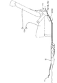
本発明の実施例であるポケット構造は、図1および図2に示す車両の車室内に形成された3つのポケット10a,10b,10cに採用されている。本実施例のポケット構造は、図1および図2に示すように、車両のフロア11に敷設された車両用内装材(乗物用内装材)としてのフロアカーペット12に対して各ポケット10a,10b,10cを形成するためのものである。それら3つのポケット10a,10b,10cは、リアシート13の下側に配されている。詳しく言えば、リアシート13は、車幅方向において左側リアシート(中間部分を含む)13Lと右側リアシート13Rとに2分割されており、3つのポケット10a,10b,10cは、左側リアシート13Lの下側に配されている。そして、フロア11には、リアシート13の下側において、上方に向かって傾斜して立ち上がる立ち上がり面11aが形成されており、その立ち上がり面11aに、3つのポケット10a,10b,10cが車幅方向に並んで配されている。
The pocket structure which is the embodiment of the present invention is adopted for the three
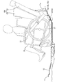
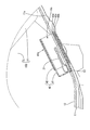
本実施例のポケット構造が採用された車両は、図1に示すように、リアシート13のシートクッション14を、車両後方側を基点して跳ね上げて、シートバック15に対して接する状態とすることが可能な構成とされている。また、助手席は、シートバックを前側に倒した状態でシートバックとシートクッションとを、車両前方側を基点として立ち上げることができるように構成されており、車室内に前後方向に広いスペースを形成することができる。そして、当該車両は、図3に示すように、そのスペースに車椅子20に乗ったまま乗車することが可能な車両となっている。
In a vehicle in which the pocket structure of the present embodiment is adopted, as shown in FIG. 1, the
乗員が車椅子20に乗ったまま乗車する際には、その車椅子20を車両に固定するための複数の固縛ベルト21(本実施例においては車椅子20が有する4つの車輪に対応する4本の固縛ベルト)や、車椅子20に座っている乗員がシートベルトをするために、シートベルトの延長ベルト22が必要となる。3つのポケット10a,10b,10cは、それら複数の固縛ベルト21および延長ベルト22を収容するためのものとなっている。そのため、それらポケット10a,10b,10cは、車椅子20を乗せる場合に利用できるよう、リアシート13の下側に配されているのである。
When an occupant rides on the
3つのポケット10a,10b,10cのうち、右側のポケット10aと中央のポケット10bとは、同じ大きさとされ、左側のポケット10cは、それら右側ポケット10aおよび中央ポケット10bに比較して、車幅方向の寸法が小さなものとされている。そして、上記の合計5本のベルト21,22のうち、右側ポケット10aと中央ポケット10bとの各々に2本ずつ収容するとともに、左側ポケット10cに残りの1本を収容することが可能とされている。
Of the three
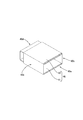
右側ポケット10aおよび中央ポケット10bは、図4A,図4Bに示す第1ポケット部材30を主体として構成され、それら第1ポケット部材30を、フロアカーペット12に取り付けることで、右側ポケット10aおよび中央ポケット10bが形成される。第1ポケット部材30は、図4A,図4Bに示すように、上下方向に長い布状(可撓性を有するシート状)の縦方向部材31と、車幅方向(左右方向)に長い布上の横方向部材32と、からなる。第1ポケット部材30は、縦方向部材31の上端部分と横方向部材32の中央部分とが縫い合わされて、概してT字形状のものとされている。
The right-
第1ポケット部材30において、縦方向部材31と横方向部材32とが縫い合わされた部分30aは、図1に示すように、右側ポケット10aおよび中央ポケット10bの車室内側の面をなす部分であり、ポケット前面部として機能する部分となっている。そして、横方向部材32におけるポケット前面部30aの車幅方向右側部分30bおよび左側部分30cが、ポケット前面部30aから左右方向の各々に延び出した一対の側方延出部として機能する部分となっている。また、縦方向部材31におけるポケット前面部30aの下側部分30dが、ポケット前面部30aから下方に延び出した下方延出部として機能する部分となっている。
In the
図4Aに示す、縦方向部材31および横方向部材32の各々の一方側の面は、ポケット前面部30aの車室内側(乗物室内側)の面を含む表面であり、この面全体が、不織布状のものとなっており、面ファスナーのループ(メスファスナー)を構成するものとなっている。一方、図4Bに示すように、第1ポケット部材30の裏面には、横方向部材32の左右の両端の各々に、面ファスナーのフック(オスファスナー)33が縫い付けられている。
The surface on one side of each of the
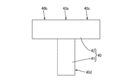
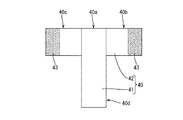
また、左側ポケット10cは、図5A,図5Bに示す第2ポケット部材40を主体として構成され、その第2ポケット部材40を、フロアカーペット12に取り付けることで、左側ポケット10cが形成される。その第2ポケット部材40は、第1ポケット部材30と類似するものであり、車幅方向の寸法が異なるものとなっている。つまり、第2ポケット部材40は、縦方向部材41と横方向部材42とからなり、縦方向部材41の上端部分と横方向部材42の中央部分とが縫い合わされて、概してT字形状のものとされている。そして、第2ポケット部材40は、第1ポケット部材30と同様に、ポケット前面部40aと、一対の側方延出部40b,40cと、下方延出部40dと、を備えるものとなっている。さらに、図5Aに示す、縦方向部材31および横方向部材32の各々の一方側の面が、不織布状のものとなっており、面ファスナーのループ(メスファスナー)を構成するとともに、図5Bに示すように、第2ポケット部材40の裏面には、横方向部材42の左右の両端の各々に、面ファスナーのフック(オスファスナー)43が縫い付けられている。
The
以上のように構成された2つのポケット部材30がフロアカーペット12に取り付けられることで、右側ポケット10aおよび中央ポケット10bが形成されるとともに、第2ポケット部材40がフロアカーペット12に取り付けられることで、左側ポケット10cが形成される。以下に、その取付方法について、図6〜図9を参照しつつ詳しく説明する。なお、3つのポケット30,40の取付方法は、同一であるため、第2ポケット部材40を代表して説明することとする。
By attaching the two
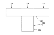
上記のように構成されたポケット部材30,40を取り付けるために、フロアカーペット12には、3組の取付部が設けられている。それら3組の取付部は、図1に示すように、フロアカーペット12におけるフロア11の立ち上がり面11aを覆う部分に設けられている。それら3組の取付部のうち第2ポケット部材40に対応する取付部50は、図6に示すように、複数のスリット51,52,53(本実施例においては3本)からなる。そして、それらのうちの2本のスリット51,52(以下の説明において、「縦スリット51,52」と呼ぶ場合がある。)は、上下方向に延びて互いに平行に形成されている。また、もう1本のスリット53(以下の説明において、「横スリット53」と呼ぶ場合がある。)は、2本の縦スリット51,52の間で、かつ、それらの下端側において、車幅方向に延びる形状に形成されている。
The
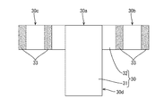
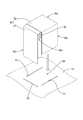
そして、フロアカーペット12に対するポケット部材30,40の取り付け作業は、フロアカーペット12をフロア11に敷設する前に行われる。上記のように形成された取付部50に対して、第2ポケット部材40を取り付ける際には、まず、第2ポケット部材40における一対の側方延出部40b,40cを折り曲げて、縦スリット51,52に挿入するとともに、下方延出部40dを折り曲げて、横スリット53に挿入する。そして、図7に示すように、まず、フロアカーペット12の背面側(下面側)において、横スリット53に挿入された下方延出部40dを、上方側(ポケット前面部40a側)に折り返す。次いで、一対の側方延出部40b,40cの一方(図8においては、車幅方向左側の側方延出部40c)を、ポケット前面部40a側に折り返す。そして、下方延出部40dの表面側つまり面ファスナーのループと、側方延出部40cの裏面側に配された面ファスナーのフックとを、重なり合わせて、互いに結合させる。続いて、一対の側方延出部40b,40cの他方(図8においては、車幅方向右側の側方延出部40b)を折り返す。その場合、側方延出部40cの表面側に配された面ファスナーのループと、側方延出部40bの裏面側に配された面ファスナーのフック43とを、重なり合わせて、互いに結合させる。それにより、図9に示すように、フロアカーペット12の車室内側の面と第2ポケット部材40との間に、ポケット10cが形成されるのである。以上で、第2ポケット部材40のフロアカーペット12への取り付けが完了し、同様に、残り2つの第1ポケット部材30を取り付けることで、3つのポケット10,a,10b,10cが形成される。
Then, the work of attaching the
以上のように、本実施例のポケット構造は、複数の延出部40b,40c,40d(30b,30c,30d)をスリット51,52,53に挿入し、それら複数の延出部40b,40c,40dを乗物用内装材であるフロアカーペット12の背面側において中央に向かって(ポケット前面部40a側に)折り返して先端を重ね合わせ、その重ね合わせた部分において互いに固定することで、乗物室内側にポケット10a,10b,10cを形成することができる。したがって、本実施例のポケット構造によれば、ポケット部材30,40の取り付けに別部材が必要なく、そのポケット部材30,40のフロアカーペット12への取付作業は簡便なものとなり、フロアカーペット12におけるポケット10a,10b,10cを容易に形成することができる。なお、複数の延出部40b,40c,40d同士の固定方法は、特に限定されないが、本実施例のポケット構造は、固定方法に面ファスナーが採用されているため、ポケット部材30,40の取付作業がより簡便なものとなっている。
As described above, in the pocket structure of the present embodiment, the plurality of extending
また、本実施例のポケット構造は、フロアカーペット12においてフロア11の立ち上がり面11aを覆う箇所に複数のスリット51,52,53が形成されているため、ポケット10a,10b,10cの開口が上方を向いているため、車両の加減速によって、ポケット10a,10b,10cからの収容物の飛び出しが回避される。特に、車両は、急ブレーキ等の可能性があるが、ポケット10a,10b,10cの開口が車両後方に向いているため、そのような場合であっても、本実施例のポケット構造によれば、ポケット10a,10b,10cからの収容物の飛び出しが回避される。
Further, in the pocket structure of the present embodiment, since the plurality of
<他の実施形態>
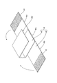
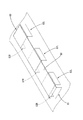
上記実施例のポケット構造においては、ポケット部材30,40が側方延出部を一対のみ、下方延出部を1つのみ備えるものとされていたが、それに限定されない。例えば、図10に示すポケット部材80は、下方延出部81は1つのみであるが、複数対の側方延出部82L,82R(図10においては、三対)を備えるものとされている。つまり、このポケット部材80を用いたポケット85は、長手方向における一端に開口している。例えば、傘等の長手状のものを収容するような場合に利用することができる。また、例えば、図11に示すポケット部材90は、側方延出部91L,91Rは一対のみであるが、複数の下方延出部92(図11においては、三対)を備えるものとすることもできる。このポケット部材90を用いたポケット95は、短手方向(幅方向)における一端に開口しているため、例えば板状のものを収容するような場合に利用することができる。さらに、ポケット部材は、複数対の側方延出部と複数の下方延出部とを備えるものとすることもできる。
<Other Embodiments>
In the pocket structure of the above embodiment, the
また、上記実施例のポケット構造は、基材(フロア11)を被覆する表皮(フロアカーペット12)に対してポケット部材30,40を取り付けるような構成であったが、樹脂性の基材に対して直接ポケット部材を取り付けるような構成であってもよい。なお、上記実施例のポケット構造は、車両のフロア11に採用されていたが、天井や側壁部に採用することもできる。
Further, although the pocket structure of the above-described embodiment has a configuration in which the
また、上記実施例のポケット構造は、車両用内装材に採用されていたが、それに限定されず、種々の乗物の内装材において採用可能である。本発明のポケット構造は、例えば、列車や遊戯用車両、飛行機やヘリコプター、船舶や潜水艇などの乗物用内装材のポケット構造に適用することができる。 Further, although the pocket structure of the above-described embodiment has been adopted as the interior material for a vehicle, it is not limited thereto, and can be adopted for interior materials of various vehicles. INDUSTRIAL APPLICABILITY The pocket structure of the present invention can be applied to a pocket structure of an interior material for vehicles such as trains, recreational vehicles, airplanes, helicopters, ships and submersibles.
10a,10b,10c…ポケット、11…フロア、11a…立ち上がり面、12…フロアカーペット、20…車椅子、21…固縛ベルト、22…延長ベルト、30…第1ポケット部材、30a…ポケット前面部、30b,30c…一対の側方延出部、30d…下方延出部、33…フック、40…第2ポケット部材、40a…ポケット前面部、40b,40c…一対の側方延出部、40d…下方延出部、43…フック、51,52…縦スリット、53…横スリット、80…ポケット部材、81…下方延出部、82L,82R…側方延出部、85…ポケット、90…ポケット部材、91L,91R…側方延出部、92…下方延出部、95…ポケット 10a, 10b, 10c... Pocket, 11... Floor, 11a... Rising surface, 12... Floor carpet, 20... Wheelchair, 21... Lashing belt, 22... Extension belt, 30... First pocket member, 30a... Pocket front part, 30b, 30c... A pair of lateral extension parts, 30d... A downward extension part, 33... Hook, 40... 2nd pocket member, 40a... Pocket front part, 40b, 40c... A pair of lateral extension parts, 40d... Downward extension part, 43... Hook, 51, 52... Vertical slit, 53... Horizontal slit, 80... Pocket member, 81... Downward extension part, 82L, 82R... Side extension part, 85... Pocket, 90... Pocket Member, 91L, 91R... Lateral extension, 92... Downward extension, 95... Pocket
Claims (6)
可撓性を有するシート状のものとされ、前記ポケットにおける乗物室内側の面をなすポケット前面部と、前記ポケット前面部から左右方向の各々に向かって延び出した少なくとも一対の側方延出部と、前記ポケット前面部から下方に向かって延び出した少なくとも1つの下方延出部と、を備えたポケット部材と、
前記乗物用内装材に設けられ、前記少なくとも一対の側方延出部および前記少なくとも1つの下方延出部を挿通させる複数のスリットと、
を含んで構成され、
前記少なくとも一対の側方延出部および前記少なくとも1つの下方延出部を乗物室内側から前記複数のスリットに挿入し、前記乗物用内装材の乗物室外側において、前記少なくとも1つの下方延出部と前記少なくとも一対の側方延出部とを互いに固定することで、前記乗物用内装材の乗物室内側の面と前記ポケット部材との間に前記ポケットを形成する乗物用内装材のポケット構造。 A pocket structure of a vehicle interior material for forming a pocket in the vehicle interior material,
A flexible sheet-like, front surface of the pocket forming a surface on the inside of the vehicle in the pocket, and at least a pair of laterally extending portions extending in the left and right directions from the front surface of the pocket. And a pocket member including at least one downward extending portion extending downward from the pocket front surface portion,
A plurality of slits provided in the interior material for a vehicle, through which the at least one pair of lateral extension portions and the at least one downward extension portion are inserted;
Is composed of
The at least one pair of laterally extending portions and the at least one downwardly extending portion are inserted into the plurality of slits from the inside of the vehicle, and the at least one downwardly extending portion is provided outside the vehicle interior of the vehicle interior material. And the at least one pair of laterally extending portions are fixed to each other to form the pocket between the surface of the interior material for a vehicle inside the vehicle and the pocket member.
前記少なくとも1つの下方延出部と前記少なくとも一対の側方延出部とを、前記面ファスナーによって互いに固定するように構成された請求項1に記載の乗物用内装材のポケット構造。 The pocket member is provided with a surface fastener at each of the end portions of the at least one pair of lateral extension portions and the end portions of the at least one downward extension portion,
The vehicle interior material pocket structure according to claim 1, wherein the at least one downward extension portion and the at least one pair of lateral extension portions are configured to be fixed to each other by the surface fastener.
前記カーペットは、前記立ち上がり面を覆う箇所に前記複数のスリットが形成された 請求項5に記載の乗物用内装材のポケット構造。 The vehicle floor on which the carpet is laid has a rising surface that rises upward,
The pocket structure of the interior material for vehicles according to claim 5, wherein the plurality of slits are formed in a portion of the carpet that covers the rising surface.
Priority Applications (2)
| Application Number | Priority Date | Filing Date | Title |
|---|---|---|---|
| JP2019013369A JP7130566B2 (en) | 2019-01-29 | 2019-01-29 | Pocket structure for vehicle interior materials |
| CN202010065050.3A CN111483400B (en) | 2019-01-29 | 2020-01-20 | Bag structure for interior parts for passenger tools |
Applications Claiming Priority (1)
| Application Number | Priority Date | Filing Date | Title |
|---|---|---|---|
| JP2019013369A JP7130566B2 (en) | 2019-01-29 | 2019-01-29 | Pocket structure for vehicle interior materials |
Publications (2)
| Publication Number | Publication Date |
|---|---|
| JP2020121602A true JP2020121602A (en) | 2020-08-13 |
| JP7130566B2 JP7130566B2 (en) | 2022-09-05 |
Family
ID=71791245
Family Applications (1)
| Application Number | Title | Priority Date | Filing Date |
|---|---|---|---|
| JP2019013369A Active JP7130566B2 (en) | 2019-01-29 | 2019-01-29 | Pocket structure for vehicle interior materials |
Country Status (2)
| Country | Link |
|---|---|
| JP (1) | JP7130566B2 (en) |
| CN (1) | CN111483400B (en) |
Cited By (1)
| Publication number | Priority date | Publication date | Assignee | Title |
|---|---|---|---|---|
| JP2020131976A (en) * | 2019-02-20 | 2020-08-31 | 三菱マヒンドラ農機株式会社 | Vehicular storage equipment |
Citations (5)
| Publication number | Priority date | Publication date | Assignee | Title |
|---|---|---|---|---|
| JPS6076549U (en) * | 1983-10-31 | 1985-05-29 | 株式会社タチエス | vehicle seat pocket |
| JPS616437U (en) * | 1984-06-19 | 1986-01-16 | 株式会社 一進研究所 | A container that can be attached to a vehicle window and a mount to make this container |
| JPS61165242U (en) * | 1985-04-01 | 1986-10-14 | ||
| JPH07329643A (en) * | 1994-06-08 | 1995-12-19 | Meiwa Ind Co Ltd | Interior trim member with pocket and its manufacture |
| JP3147383U (en) * | 2008-10-15 | 2008-12-25 | 久雄 桜庭 | Armrest |
Family Cites Families (5)
| Publication number | Priority date | Publication date | Assignee | Title |
|---|---|---|---|---|
| JP2001070090A (en) * | 1999-09-06 | 2001-03-21 | Takehiro:Kk | Seat back pocket structure and seat back back surface member and seat for vehicle |
| JP4505424B2 (en) * | 2006-03-17 | 2010-07-21 | ホシデン株式会社 | Jack |
| CN102700498A (en) * | 2012-06-28 | 2012-10-03 | 王伟 | Device for assisting safety belt |
| CN205054537U (en) * | 2015-09-11 | 2016-03-02 | 新疆医科大学第六附属医院 | Medical arm fixing straps |
| CN205837424U (en) * | 2016-04-25 | 2016-12-28 | 吴松柏 | A load-bearing folding turnover packaging box |
-
2019
- 2019-01-29 JP JP2019013369A patent/JP7130566B2/en active Active
-
2020
- 2020-01-20 CN CN202010065050.3A patent/CN111483400B/en active Active
Patent Citations (5)
| Publication number | Priority date | Publication date | Assignee | Title |
|---|---|---|---|---|
| JPS6076549U (en) * | 1983-10-31 | 1985-05-29 | 株式会社タチエス | vehicle seat pocket |
| JPS616437U (en) * | 1984-06-19 | 1986-01-16 | 株式会社 一進研究所 | A container that can be attached to a vehicle window and a mount to make this container |
| JPS61165242U (en) * | 1985-04-01 | 1986-10-14 | ||
| JPH07329643A (en) * | 1994-06-08 | 1995-12-19 | Meiwa Ind Co Ltd | Interior trim member with pocket and its manufacture |
| JP3147383U (en) * | 2008-10-15 | 2008-12-25 | 久雄 桜庭 | Armrest |
Cited By (2)
| Publication number | Priority date | Publication date | Assignee | Title |
|---|---|---|---|---|
| JP2020131976A (en) * | 2019-02-20 | 2020-08-31 | 三菱マヒンドラ農機株式会社 | Vehicular storage equipment |
| JP7217168B2 (en) | 2019-02-20 | 2023-02-02 | 三菱マヒンドラ農機株式会社 | vehicle container |
Also Published As
| Publication number | Publication date |
|---|---|
| CN111483400A (en) | 2020-08-04 |
| JP7130566B2 (en) | 2022-09-05 |
| CN111483400B (en) | 2023-10-20 |
Similar Documents
| Publication | Publication Date | Title |
|---|---|---|
| US9597990B2 (en) | Internal map pocket | |
| JP4852115B2 (en) | Cargo net for vehicles | |
| JP6135435B2 (en) | Vehicle seat | |
| JP6702138B2 (en) | Vehicle seat | |
| JP6900807B2 (en) | Interior goods | |
| JP6491255B2 (en) | Vehicle seat | |
| JP2001315558A (en) | Child seat | |
| JP6341431B2 (en) | Sheet device | |
| US10279713B2 (en) | Vehicle seat | |
| JP2020121602A (en) | Pocket structure of interior material for vehicle | |
| JP6812228B2 (en) | Vehicle seats and methods for manufacturing vehicle seats | |
| JP6946232B2 (en) | Vehicle seat | |
| JP5780144B2 (en) | Seat belt buckle storage structure | |
| JP6677104B2 (en) | Vehicle interior structure | |
| JP3187335U (en) | Storage | |
| JP5870859B2 (en) | Clearance structure of seat belt buckle | |
| JP5577178B2 (en) | Car bag | |
| JP6495961B2 (en) | Vehicle seat | |
| JP6450796B2 (en) | Vehicle seat | |
| JP6533563B2 (en) | Body structure | |
| JP7210420B2 (en) | vehicle seat | |
| JP2019094010A (en) | Vehicle seat | |
| JP6822287B2 (en) | Vehicle seat | |
| JP6699404B2 (en) | Vehicle seat | |
| JP2026005803A (en) | Bolster |
Legal Events
| Date | Code | Title | Description |
|---|---|---|---|
| A621 | Written request for application examination |
Free format text: JAPANESE INTERMEDIATE CODE: A621 Effective date: 20210726 |
|
| TRDD | Decision of grant or rejection written | ||
| A977 | Report on retrieval |
Free format text: JAPANESE INTERMEDIATE CODE: A971007 Effective date: 20220727 |
|
| A01 | Written decision to grant a patent or to grant a registration (utility model) |
Free format text: JAPANESE INTERMEDIATE CODE: A01 Effective date: 20220802 |
|
| A61 | First payment of annual fees (during grant procedure) |
Free format text: JAPANESE INTERMEDIATE CODE: A61 Effective date: 20220824 |
|
| R150 | Certificate of patent or registration of utility model |
Ref document number: 7130566 Country of ref document: JP Free format text: JAPANESE INTERMEDIATE CODE: R150 |
|
| R250 | Receipt of annual fees |
Free format text: JAPANESE INTERMEDIATE CODE: R250 |