JP2020131069A - Coating device and image forming system - Google Patents
Coating device and image forming system Download PDFInfo
- Publication number
- JP2020131069A JP2020131069A JP2019024342A JP2019024342A JP2020131069A JP 2020131069 A JP2020131069 A JP 2020131069A JP 2019024342 A JP2019024342 A JP 2019024342A JP 2019024342 A JP2019024342 A JP 2019024342A JP 2020131069 A JP2020131069 A JP 2020131069A
- Authority
- JP
- Japan
- Prior art keywords
- roller
- coating
- liquid
- scraper
- contact
- Prior art date
- Legal status (The legal status is an assumption and is not a legal conclusion. Google has not performed a legal analysis and makes no representation as to the accuracy of the status listed.)
- Granted
Links
Images


Landscapes
- Ink Jet (AREA)
- Coating Apparatus (AREA)
Abstract
【課題】塗布ローラの端部における過剰な液溜まりを確実に防止する。
【解決手段】被塗布体に塗布液を塗布する塗布ローラと、該塗布ローラの液供給経路の上流側に配置され該塗布ローラに直接的に若しくは間接的に前記塗布液を供給する少なくとも一つのローラとを備えて構成される塗布装置において、前記少なくとも一つのローラの端部に当接するスクレーパーを設ける。
【選択図】図2PROBLEM TO BE SOLVED: To surely prevent excessive liquid accumulation at an end portion of a coating roller.
SOLUTION: A coating roller that applies a coating liquid to an object to be coated, and at least one that is arranged on the upstream side of a liquid supply path of the coating roller and directly or indirectly supplies the coating liquid to the coating roller. In a coating apparatus including a roller, a scraper is provided that abuts on the end of at least one roller.
[Selection diagram] Fig. 2
Description
本発明は、塗布装置と該塗布装置を組み込んだ画像形成システムとに関するものである。 The present invention relates to a coating device and an image forming system incorporating the coating device.
処理液槽に溜められた処理液を複数のローラを介して汲み上げて、用紙等の記録材に汲み上げた処理液を塗布する技術が考えられ、既に知られている。
例えば、特許文献1では、塗布ローラの両端部に液溜まりが生じるのを防止するために、塗布ローラの処理液供給上流側にある供給ローラの幅を塗布ローラの幅よりも広く形成すると共に、供給ローラの塗布ローラと接触しない領域の表面状態を処理液が流れ易いように濡れ性を高く構成することが提案されている。
A technique of pumping the treatment liquid stored in the treatment liquid tank through a plurality of rollers and applying the pumped treatment liquid to a recording material such as paper has been considered and is already known.
For example, in Patent Document 1, in order to prevent liquid pools from forming at both ends of the coating roller, the width of the supply roller on the upstream side of the treatment liquid supply of the coating roller is formed wider than the width of the coating roller. It has been proposed that the surface condition of the region that does not come into contact with the coating roller of the supply roller is configured to have high wettability so that the treatment liquid can easily flow.
塗布ローラの長手方向端部では液が溜まり易く、ローラ長手方向の中央部よりも端部で液の溜まり量が多くなり、塗布対象の記録材の幅方向で塗布ムラが生じる。引用文献1では、液をローラの軸方向に流れ易くしているだけなので、液の粘度が変化する場合等に塗布ローラ端部の過剰な液溜まりを確実に防止することが保証されない。 Liquid tends to collect at the end of the coating roller in the longitudinal direction, and the amount of liquid that collects at the end is larger than that at the center in the longitudinal direction of the roller, causing uneven coating in the width direction of the recording material to be coated. In Cited Document 1, since the liquid is only facilitated to flow in the axial direction of the roller, it is not guaranteed to reliably prevent excessive liquid accumulation at the end of the coating roller when the viscosity of the liquid changes.
本発明の課題は、塗布ローラの端部における過剰な液溜まりを確実に防止することにある。 An object of the present invention is to reliably prevent excessive liquid accumulation at the end of the coating roller.
上記課題を解決するため、本発明は、被塗布体に塗布液を塗布する塗布ローラと、該塗布ローラの液供給経路の上流側に配置され該塗布ローラに直接的に若しくは間接的に前記塗布液を供給する少なくとも一つのローラとを備えて構成される塗布装置において、前記少なくとも一つのローラの端部に当接するスクレーパーを設けることを特徴とする。 In order to solve the above problems, the present invention comprises a coating roller for applying a coating liquid to an object to be coated, and the coating roller arranged on the upstream side of the liquid supply path of the coating roller and directly or indirectly on the coating roller. A coating device including at least one roller for supplying liquid is provided with a scraper that abuts on the end of the at least one roller.
本発明によれば、塗布ローラの端部における過剰な液溜まりを確実に防止することができる。 According to the present invention, it is possible to reliably prevent excessive liquid accumulation at the end of the coating roller.
以下、添付図面を参照しながら本発明の好適な実施の形態について説明する。
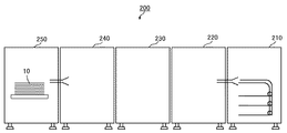
図1は、本発明の一実施形態に係る画像形成システム200の全体を観念的に説明する図である。画像形成システム200は、給紙装置210、前処理液塗布装置220、インクジェットプリンタ230、乾燥装置240、排紙装置250を備えている。
Hereinafter, preferred embodiments of the present invention will be described with reference to the accompanying drawings.
FIG. 1 is a diagram for conceptually explaining the entire
給紙装置210は、一般のオフセット印刷等で使用される汎用の用紙(セルロースを主体とする上質紙やコート紙等)である記録材10を、記録材10の搬送経路下流側に設けられた前処理液塗布装置220に供給する。
The
塗布装置である前処理液塗布装置220は、後述するように、記録媒体10上に印刷されるインクの滲みを抑える前処理液を、記録材10に塗布するもので、汎用の用紙をインクジェット印刷に使用可能にするものである。前処理液塗布装置220には、周知のように、反転パスが備えられ、両面印刷を行う場合、記録材10の表側に前処理液を塗布した後、記録材10を反転させて、裏側にも前処理液を塗布できる構造となっている。
As will be described later, the pretreatment
インク吐出装置であるインクジェットプリンタ230は、前処理液塗布装置220において前処理液が塗布された記録材10の表側にインク滴を吐出して所望の画像を形成する。
乾燥装置240は、周知のように、ドライヤを備え、インクジェットプリンタ230で形成された記録材10の表側の画像を乾燥させる。記録材10の表裏に印刷する場合、記録材10は乾燥装置240からインクジェットプリンタ230へ戻る周知のパスにより反転されて、インクジェットプリンタ230で表裏が反転された記録材10の表側(反転前の裏側)にインク滴を吐出して所望の画像が形成され、乾燥装置240で記録材10の表側(反転前の裏側)の画像を乾燥させる。その後、記録材10は排紙装置250に排出される。
The
As is well known, the
図2、図3において、本発明の一実施形態に係る前処理液塗布装置220における多段ローラ構成を説明する。液収容部である供給パン7は、前処理液/先塗り液である塗布液8が一定量収容できる構成になっており、汲み上げローラ1の一部が塗布液8に浸かった状態で配置されている。汲み上げローラ1の上方には、即ち、液供給経路の下流側には、汲み上げローラからの塗布液の量を調整する絞りローラ2(汲み上げローラ1から塗布液8を受ける受けローラ)、絞りローラ側の圧力と共に加圧ローラ5の側の圧力も受ける中間ローラ3、記録材に塗布液を塗布する塗布ローラ4が順に配置され、供給パン7、汲み上げローラ1と共に塗布ユニットを構成している。汲み上げローラ1と絞りローラ2は供給パン7に支承されていて、中間ローラ3と塗布ローラ4は装置フレームに支承され、更に塗布ローラ4は、上下方向に任意の距離だけ変位可能な構造になっている。また、塗布ローラ4の上方には加圧部40を構成する加圧ローラ5と押さえローラ6が配置されており、塗布ローラ4と加圧ローラ5に挟持されるようにして被塗布体である記録材10が搬送されるようになっている。
2 and 3 show a multi-stage roller configuration in the pretreatment
多段ローラ方式では、複数のローラがあるがゆえに塗布量に影響を与える要因の一つにローラ間の圧力があり、金属のような剛性の高いローラとゴムのような柔らかい素材のローラが交互に隣接して配置されていることが多い。図示の例では、汲み上げローラ1は金属ローラ、絞りローラ2はゴムローラ、中間ローラ3は金属ローラ、塗布ローラ4はゴムローラ、加圧ローラ5は金属ローラ、押さえローラ6はゴムローラで構成されている。汲み上げローラ1から塗布ローラ4までのローラ構成では、金属ローラよりもゴムローラの長さがやや短い構成となっている。これは、金属ローラに挟まれたゴムローラの長手方向全面に圧力が掛かるようにするためで、金属ローラよりもゴムローラが長いと、圧力が掛かる部分と掛からない部分でゴムの変形が発生するためである。
In the multi-stage roller method, pressure between the rollers is one of the factors that affect the coating amount because there are multiple rollers, and rollers with high rigidity such as metal and rollers made of soft material such as rubber alternate. Often placed adjacent to each other. In the illustrated example, the pumping roller 1 is a metal roller, the
ここで、汲み上げローラ1により汲み上げられた塗布液8は、絞りローラ2の全面に行き渡り、両端部の端面付近に塗布液8の液溜まりが多く発生する。これは、ローラ間の圧力により絞りローラ2側に抜けられない塗布液8が両端部に逃げていくためである。そのため、絞りローラ2の両端部に塗布液8の液溜まりが多くなり、その結果、中間ローラ3の端部付近により多くの塗布液8が供給され得ることになる。更に、中間ローラ3から塗布ローラ4への塗布液8の通過を考えると、汲み上げローラ1及び絞りローラ2と同様、塗布ローラ4の両端部に塗布液8の液溜まりが多くなって、記録材10の端部に過剰な塗布液8が塗布され得ることとなる。
Here, the coating liquid 8 pumped up by the pumping roller 1 spreads over the entire surface of the
このような記録材10の端部への塗布液8の過剰供給を回避する構成を備えることが本発明の骨子であり、供給ローラである中間ローラ3の長手方向に沿って、スクレーパー20が配置される。スクレーパー20は、ゴムや樹脂フィルムのような弾性体でできており、中間ローラ3の長手方向において塗布ローラ4の端部で中間ローラ3に接触可能に配置され、モータ30の動作によって、その両端域(長手方向両方の端部若しくは端部近傍)が中間ローラ3に接触し、あるいは離間する。スクレーパー20は中間ローラ3と接触する部分(両端域)以外は、接触動作時に中間ローラ3に接触しないよう切り欠かれた形状になっている。スクレーパー20は、少なくとも、塗布ローラ4の端部の縁(即ち、図2において矩形状に示された塗布ローラ4の左右の辺)に対応する位置で、中間ローラ3に接触可能に配置されている。スクレーパー20は、中間ローラ3の端部の縁(即ち、図2において矩形状に示された中間ローラ3の左右の辺)よりも所定距離だけ内側の位置から、ローラ長手方向の中央側へ向かって、塗布ローラ4の端部の縁を超える位置まで設けられることが好ましい。また、スクレーパー20の幅は、両端でそれぞれ50mm以下とすることが好ましい。また、40mm以上とすることが好ましい。
The gist of the present invention is to have a configuration for avoiding such an excessive supply of the coating liquid 8 to the end portion of the
また、スクレーパー20の中間ローラ3との接触状態、あるいは離間状態は、既知のセンサーにより検知され、接触状態においては或る範囲内で接触圧力が可変であるような構造になっている。例えば、液粘度が変わることにより通常よりも塗布液8の付着量が変わり得る場合等は、スクレーパー20の接触圧力を変えることによって端部の塗布量を、即ち、液溜まりの量を調整することができる。塗布量が実際にどの程度かを見て判断することは難しいため、液粘度による塗布液8の付着量の変化に関して、例えば液温による粘度変化を事前にデータ取得しておいて、それを利用して供給パン7に設置された温度計の検知結果に基づいてスクレーパー20の接触圧力を変更することが考えられる。記録材10の中央域と端部域で印刷品質等に差がある場合等には、フィードバック処理としてスクレーパー20の接触圧力を変更してもよく、印刷品質の向上に有効な手段となる。
Further, the contact state or the separation state of the
スクレーパー20により掻き落とされた塗布液8はスクレーパー20を伝って供給パン7内に戻される構造になっていて、余分な塗布液を各ローラに移る事態を回避する。印刷動作により各ローラが回転するとスクレーパー20は中間ローラ3に接触し、印刷停止で各ローラが停止すると、スクレーパー20は中間ローラ3から離間するようになっている。
The coating liquid 8 scraped off by the
また、スクレーパー20は金属ローラである中間ローラ3に接触するものであるため、交換可能な構造となっており、スクレーパー20が中間ローラ3から離間した状態で任意のギャップとなるよう取り付けることで、押し付けの圧力や離間時のギャップが再現できる構造になっている。
Further, since the
印刷を行わない時(非印刷時)には、加圧部40の加圧ローラ5、押さえローラ6がモータ34により上方の退避位置へ移動する構造となっており、加圧ローラ5と塗布ローラ4のニップ状態が解除される形となる。また、供給パン7はモータ31により下方へ移動する構造となっており、中間ローラ3と絞りローラ2のニップ状態が解除される。汲み上げローラ1、絞りローラ2及び中間ローラ3は、モータ32が駆動することにより、各ローラに取り付けられたギヤ等の伝動装置を介して所定の速度で回転する。同様に、塗布ローラ4、加圧ローラ5及び押さえローラ6は、モータ33が駆動することにより、各ローラに取り付けられたギヤ等の伝動装置を介して所定の速度で回転する。モータ32とモータ33は共通化することも可能である。
When printing is not performed (during non-printing), the pressurizing roller 5 and the pressing roller 6 of the pressurizing
モータ31の駆動で供給パン7が移動し、絞りローラ2を中間ローラ3に押し付けているが、その押し付け力を変えることで中間ローラ3及び塗布ローラ4への塗布液8の量をコントロールすることができる。
The supply pan 7 is moved by the drive of the
スクレーパー20は周知のメカニカルによって中間ローラ3に接離可能に配置されているが、図3の矢印方向に、即ち、塗布液8が汲み上がってくる方向に配置されている(矢印は液が流れていく経路、即ち、液供給経路を示す)。このため、中間ローラ3から塗布ローラ4に移動する塗布液8の量をコントロールすることができる。また、スクレーパー20が中間ローラ3の周面汲み上げ方向に配置されているため、万が一、記録材10が塗布ローラ4側に巻き付き、中間ローラ3側に至っても、スクレーパー20が配置されている側とは反対側(中間ローラ3の汲み上げ側とは反対側)に巻き込まれることになるので、そちら側に巻き付き防止用の爪等を配置しておくことにより記録材を取り除くことができるため、スクレーパー20には影響しない。
The
なお、押さえローラ6、加圧ローラ5は両端の軸側に圧力が掛けられるため、中央部よりも両端部の圧力が大きくなる傾向にある。このため、塗布ローラ4の下方に位置する中間ローラ3の表面は、長手方向に対してクラウン形状(中央部が凸形状/正クラウン状)となっており、中間ローラ3と反対側の箇所で、即ち、中間ローラ当接箇所とは異なる箇所で当接する加圧ローラ5からの加圧力に対抗して、塗布ローラ4の長手方向の圧力を均一にする構造になっている。 Since pressure is applied to the shaft sides of both ends of the pressing roller 6 and the pressure roller 5, the pressure at both ends tends to be higher than that at the center. Therefore, the surface of the intermediate roller 3 located below the coating roller 4 has a crown shape (convex shape at the center / regular crown shape) with respect to the longitudinal direction, and is located on the side opposite to the intermediate roller 3. That is, the structure is such that the pressure in the longitudinal direction of the coating roller 4 is made uniform against the pressing force from the pressurizing roller 5 that abuts at a location different from the intermediate roller abutting portion.
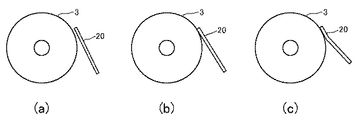
図4に、中間ローラとスクレーパーの位置関係を示し、両者の接離状態と接触圧力が変化することを説明する。図4aは、非印刷時における中間ローラ3とスクレーパー20の位置関係を示す。非印刷時は中間ローラ3が回転していないため、スクレーパー20が中間ローラ3に接触したままであると、スクレーパー20は中間ローラ3周面の同じ箇所に接触し続けることとなり、中間ローラ3とスクレーパー20の間に一定の液溜まりを形成したまま長時間放置されることとなってしまう。そうであると、塗布液8が増粘し、スクレーパー20が中間ローラ3に張り付いてしまい、次に中間ローラ3が回転する際にスクレーパー20に過剰な力が掛かる可能性がある。このため、非印刷時には、スクレーパー20を中間ローラ3から離間させ、スクレーパー20に過剰な力が加わらないように、制御されている。
FIG. 4 shows the positional relationship between the intermediate roller and the scraper, and explains that the contact / separation state and the contact pressure of the two change. FIG. 4a shows the positional relationship between the intermediate roller 3 and the
図4b、図4cは、印刷時の中間ローラ3とスクレーパー20の位置関係から接触圧力の状態が異なることを示す。印刷時はスクレーパー20が中間ローラ3と接触するよう制御されるが、スクレーパー20の接触圧力を変更することで中間ローラ3表面の塗布液8を掻き落とす量を調整することができる。
4b and 4c show that the contact pressure state is different from the positional relationship between the intermediate roller 3 and the
中間ローラ3表面の塗布液8を少なめに掻き落とす場合、図4bに示すように、中間ローラ3の接線方向に一致するようスクレーパー20を当接させる制御を行う。一方、中間ローラ3表面の塗布液8を多めに掻き落とす場合、図4cに示すように、スクレーパー20がやや変形するような接触圧力で中間ローラ3に当接させる制御を行う。
When the coating liquid 8 on the surface of the intermediate roller 3 is scraped off slightly, the
スクレーパー20は、少なくとも中間ローラ3と当接する部分の材質がゴムや樹脂等の弾性体で出来ており、押し付け圧を変えることにより中間ローラ3表面に当接しながら変形することができ、塗布量を調整できる。接触圧力は任意の範囲で変更可能な構造になっており、押し付けすぎによる永久変形が起きないよう、最大押し付け力でも弾性体変形の許容加重となる位置に調整されている。
The
以上説明した実施の形態では、供給ローラである中間ローラ3にスクレーパー20を当接させている。ロータ端部の塗布液を記録材へ過剰に塗布しない事態を防ぐためには、塗布ローラ自体にスクレーパーを当接させる構成も考えられる。しかしながら、このような構成の場合、スクレーパーのローラ中央側の縁部分に塗布液が集中することがあり、被塗布体である記録材にスジ状に塗布液が集中して塗布される可能性がある。そのため、本実施の形態では、塗布ローラよりも液供給経路の上流側のローラにスクレーパーを当接させる構成としている。また、スクレーパー20を塗布ローラ4のすぐ上流側の、即ち、塗布ローラ4に直接的に塗布液を供給する中間ローラ3に当接させ、塗布ローラ4の両端部に塗布液が溜まる事態を確実に回避している。塗布液を汲み上げた後のローラである汲み上げローラ1や絞りローラ2に、したがって塗布ローラよりも液供給経路の上流側に配置され塗布ローラ4に間接的に塗布液を供給する少なくともいずれかのローラにスクレーパーを設けることも可能であるが、この場合、中間ローラ3にスクレーパーを付設する構成よりも塗布ローラ4の端部に塗布液が多くなる傾向がある。これを避けるために、塗布ローラ4のすぐ上流側の中間ローラ3の端部周面に切り欠き部を形成して、中間ローラ3の端部で塗布液が逃げるように構成することが考えられる。あるいは、スクレーパー自体や汲み上げローラ1/絞りローラ2の長さを塗布ローラ4や中間ローラ3の長さよりも長くし、塗布ローラ4/中間ローラ3の端部での塗布液供給の量を抑制することも考えられる。
In the embodiment described above, the
1 汲み上げローラ
2 絞りローラ
3 中間ローラ
4 塗布ローラ
5 加圧ローラ
6 押さえローラ
7 供給パン
8 塗布液
20 塗布ユニット
40 加圧部
1 Pumping
Claims (9)
前記少なくとも一つのローラの端部に当接するスクレーパーを設けることを特徴とする塗布装置。 A coating roller for applying the coating liquid to the object to be coated and at least one roller arranged on the upstream side of the liquid supply path of the coating roller and directly or indirectly supplying the coating liquid to the coating roller are provided. In the coating device composed of
A coating device comprising a scraper that abuts on the end of at least one roller.
Priority Applications (1)
| Application Number | Priority Date | Filing Date | Title |
|---|---|---|---|
| JP2019024342A JP7286990B2 (en) | 2019-02-14 | 2019-02-14 | Coating device and image forming system |
Applications Claiming Priority (1)
| Application Number | Priority Date | Filing Date | Title |
|---|---|---|---|
| JP2019024342A JP7286990B2 (en) | 2019-02-14 | 2019-02-14 | Coating device and image forming system |
Publications (2)
| Publication Number | Publication Date |
|---|---|
| JP2020131069A true JP2020131069A (en) | 2020-08-31 |
| JP7286990B2 JP7286990B2 (en) | 2023-06-06 |
Family
ID=72261664
Family Applications (1)
| Application Number | Title | Priority Date | Filing Date |
|---|---|---|---|
| JP2019024342A Active JP7286990B2 (en) | 2019-02-14 | 2019-02-14 | Coating device and image forming system |
Country Status (1)
| Country | Link |
|---|---|
| JP (1) | JP7286990B2 (en) |
Citations (12)
| Publication number | Priority date | Publication date | Assignee | Title |
|---|---|---|---|---|
| JPS61286868A (en) * | 1985-06-14 | 1986-12-17 | Ricoh Co Ltd | Developer supply device |
| JPH02268869A (en) * | 1989-04-10 | 1990-11-02 | Konica Corp | Gravure coating method |
| JPH0619355A (en) * | 1992-04-20 | 1994-01-28 | Xerox Corp | Apparatus and method for coating of transfer-preventing liquid |
| JPH0611863U (en) * | 1992-07-08 | 1994-02-15 | 大日本スクリーン製造株式会社 | Roll coater |
| JP2000296352A (en) * | 1999-04-13 | 2000-10-24 | Minolta Co Ltd | Liquid material supplying device and image forming device |
| JP2002096007A (en) * | 2000-09-21 | 2002-04-02 | Nec Kagoshima Ltd | Roll coater and coating method using the same |
| JP2002278340A (en) * | 2001-03-15 | 2002-09-27 | Canon Inc | Oil application device, oil application roller, and method of manufacturing oil application roller |
| JP2003255744A (en) * | 2002-02-27 | 2003-09-10 | Canon Inc | Fixing device and image forming apparatus using the same |
| JP2003340345A (en) * | 2002-05-29 | 2003-12-02 | Fuji Photo Film Co Ltd | Doctor blade for gravure coating and gravure coating method |
| JP2004344768A (en) * | 2003-05-22 | 2004-12-09 | Toppan Printing Co Ltd | Roll coater and package substrate manufacturing method using the same |
| JP2006011070A (en) * | 2004-06-25 | 2006-01-12 | Kyocera Mita Corp | Cleaning apparatus for wet image forming apparatus |
| JP2009226240A (en) * | 2008-03-19 | 2009-10-08 | Fujifilm Corp | Coating solution feeder and inkjet recording apparatus |
-
2019
- 2019-02-14 JP JP2019024342A patent/JP7286990B2/en active Active
Patent Citations (12)
| Publication number | Priority date | Publication date | Assignee | Title |
|---|---|---|---|---|
| JPS61286868A (en) * | 1985-06-14 | 1986-12-17 | Ricoh Co Ltd | Developer supply device |
| JPH02268869A (en) * | 1989-04-10 | 1990-11-02 | Konica Corp | Gravure coating method |
| JPH0619355A (en) * | 1992-04-20 | 1994-01-28 | Xerox Corp | Apparatus and method for coating of transfer-preventing liquid |
| JPH0611863U (en) * | 1992-07-08 | 1994-02-15 | 大日本スクリーン製造株式会社 | Roll coater |
| JP2000296352A (en) * | 1999-04-13 | 2000-10-24 | Minolta Co Ltd | Liquid material supplying device and image forming device |
| JP2002096007A (en) * | 2000-09-21 | 2002-04-02 | Nec Kagoshima Ltd | Roll coater and coating method using the same |
| JP2002278340A (en) * | 2001-03-15 | 2002-09-27 | Canon Inc | Oil application device, oil application roller, and method of manufacturing oil application roller |
| JP2003255744A (en) * | 2002-02-27 | 2003-09-10 | Canon Inc | Fixing device and image forming apparatus using the same |
| JP2003340345A (en) * | 2002-05-29 | 2003-12-02 | Fuji Photo Film Co Ltd | Doctor blade for gravure coating and gravure coating method |
| JP2004344768A (en) * | 2003-05-22 | 2004-12-09 | Toppan Printing Co Ltd | Roll coater and package substrate manufacturing method using the same |
| JP2006011070A (en) * | 2004-06-25 | 2006-01-12 | Kyocera Mita Corp | Cleaning apparatus for wet image forming apparatus |
| JP2009226240A (en) * | 2008-03-19 | 2009-10-08 | Fujifilm Corp | Coating solution feeder and inkjet recording apparatus |
Also Published As
| Publication number | Publication date |
|---|---|
| JP7286990B2 (en) | 2023-06-06 |
Similar Documents
| Publication | Publication Date | Title |
|---|---|---|
| JP5364657B2 (en) | Drum maintenance system to reduce double-sided dropout | |
| JP6205939B2 (en) | Treatment liquid application device for inkjet printer | |
| JP5879929B2 (en) | Treatment liquid coating apparatus for inkjet printer, operating method of the coating apparatus, and image forming system | |
| JP6287262B2 (en) | Coating apparatus and image forming system | |
| JP5225407B2 (en) | Matting agent applying apparatus and ink jet recording apparatus | |
| US8646906B2 (en) | Image recording device and image recording method | |
| JP5597485B2 (en) | Cleaning device, coating device, and image forming apparatus | |
| JP6527073B2 (en) | System and method for image processing in an aqueous ink jet printer | |
| WO2014054615A1 (en) | Inkjet head cleaning device and cleaning method, and inkjet printing device | |
| JP2011031618A (en) | System for reducing abrasion of metering blade in drum maintenance unit | |
| US8220918B2 (en) | Spreader module for duplex continuous feed imaging devices | |
| JP2019038142A (en) | Cleaning device, image formation device, control method, and control program | |
| JP4349411B2 (en) | Liquid ejection device | |
| JP2015039781A (en) | Wiping device | |
| JP7095464B2 (en) | Processing liquid application device and image formation system | |
| JP2020131069A (en) | Coating device and image forming system | |
| JP5919744B2 (en) | Inkjet recording device | |
| JP2018164980A (en) | Inkjet printer | |
| US9427992B2 (en) | System and method for lead edge release coating for improved media stripping in an aqueous inkjet printer | |
| JP2011194619A (en) | Image forming apparatus and processing liquid coating apparatus | |
| JP5803113B2 (en) | Image forming apparatus and processing liquid coating apparatus | |
| KR20200016802A (en) | Printing apparatus, and printing method | |
| JP5234421B2 (en) | Image forming apparatus | |
| JP2012179724A (en) | Printing method and inkjet recording apparatus | |
| JP5182083B2 (en) | Image forming apparatus |
Legal Events
| Date | Code | Title | Description |
|---|---|---|---|
| A621 | Written request for application examination |
Free format text: JAPANESE INTERMEDIATE CODE: A621 Effective date: 20211025 |
|
| RD04 | Notification of resignation of power of attorney |
Free format text: JAPANESE INTERMEDIATE CODE: A7424 Effective date: 20220203 |
|
| RD07 | Notification of extinguishment of power of attorney |
Free format text: JAPANESE INTERMEDIATE CODE: A7427 Effective date: 20220301 |
|
| A977 | Report on retrieval |
Free format text: JAPANESE INTERMEDIATE CODE: A971007 Effective date: 20220815 |
|
| A131 | Notification of reasons for refusal |
Free format text: JAPANESE INTERMEDIATE CODE: A131 Effective date: 20220823 |
|
| A521 | Request for written amendment filed |
Free format text: JAPANESE INTERMEDIATE CODE: A523 Effective date: 20221018 |
|
| A131 | Notification of reasons for refusal |
Free format text: JAPANESE INTERMEDIATE CODE: A131 Effective date: 20221213 |
|
| A521 | Request for written amendment filed |
Free format text: JAPANESE INTERMEDIATE CODE: A523 Effective date: 20230206 |
|
| A131 | Notification of reasons for refusal |
Free format text: JAPANESE INTERMEDIATE CODE: A131 Effective date: 20230214 |
|
| A521 | Request for written amendment filed |
Free format text: JAPANESE INTERMEDIATE CODE: A523 Effective date: 20230410 |
|
| TRDD | Decision of grant or rejection written | ||
| A01 | Written decision to grant a patent or to grant a registration (utility model) |
Free format text: JAPANESE INTERMEDIATE CODE: A01 Effective date: 20230425 |
|
| A61 | First payment of annual fees (during grant procedure) |
Free format text: JAPANESE INTERMEDIATE CODE: A61 Effective date: 20230508 |
|
| R151 | Written notification of patent or utility model registration |
Ref document number: 7286990 Country of ref document: JP Free format text: JAPANESE INTERMEDIATE CODE: R151 |