JP2020132019A - Vehicular cargo compartment structure - Google Patents

Vehicular cargo compartment structure Download PDF

Info

Publication number
JP2020132019A
JP2020132019A JP2019029826A JP2019029826A JP2020132019A JP 2020132019 A JP2020132019 A JP 2020132019A JP 2019029826 A JP2019029826 A JP 2019029826A JP 2019029826 A JP2019029826 A JP 2019029826A JP 2020132019 A JP2020132019 A JP 2020132019A
Authority
JP
Japan
Prior art keywords
luggage compartment
board
vehicle
seat
luggage
Prior art date
Legal status (The legal status is an assumption and is not a legal conclusion. Google has not performed a legal analysis and makes no representation as to the accuracy of the status listed.)
Granted
Application number
JP2019029826A
Other languages
Japanese (ja)
Other versions
JP6878479B2 (en
Inventor
将希 奈良
Masaki Nara
将希 奈良
Current Assignee (The listed assignees may be inaccurate. Google has not performed a legal analysis and makes no representation or warranty as to the accuracy of the list.)
Honda Motor Co Ltd
Original Assignee
Honda Motor Co Ltd
Priority date (The priority date is an assumption and is not a legal conclusion. Google has not performed a legal analysis and makes no representation as to the accuracy of the date listed.)
Filing date
Publication date
Application filed by Honda Motor Co Ltd filed Critical Honda Motor Co Ltd
Priority to JP2019029826A priority Critical patent/JP6878479B2/en
Priority to CN201911140540.9A priority patent/CN111591218A/en
Publication of JP2020132019A publication Critical patent/JP2020132019A/en
Application granted granted Critical
Publication of JP6878479B2 publication Critical patent/JP6878479B2/en
Active legal-status Critical Current
Anticipated expiration legal-status Critical

Links

Images

Classifications

    • BPERFORMING OPERATIONS; TRANSPORTING
    • B60VEHICLES IN GENERAL
    • B60RVEHICLES, VEHICLE FITTINGS, OR VEHICLE PARTS, NOT OTHERWISE PROVIDED FOR
    • B60R5/00Compartments within vehicle body primarily intended or sufficiently spacious for trunks, suit-cases, or the like
    • B60R5/04Compartments within vehicle body primarily intended or sufficiently spacious for trunks, suit-cases, or the like arranged at rear of vehicle
    • BPERFORMING OPERATIONS; TRANSPORTING
    • B62LAND VEHICLES FOR TRAVELLING OTHERWISE THAN ON RAILS
    • B62DMOTOR VEHICLES; TRAILERS
    • B62D25/00Superstructure or monocoque structure sub-units; Parts or details thereof not otherwise provided for
    • B62D25/08Front or rear portions
    • B62D25/087Luggage compartments

Landscapes

  • Engineering & Computer Science (AREA)
  • Mechanical Engineering (AREA)
  • Chemical & Material Sciences (AREA)
  • Combustion & Propulsion (AREA)
  • Transportation (AREA)
  • Vehicle Step Arrangements And Article Storage (AREA)

Abstract

【課題】荷室に荷物を出し入れする際の作業性の向上と、ボード上に載せる荷物の積載量の増加と、を図ることができる車両用荷室構造を提供することを課題とする。【解決手段】車両用荷室構造は、車両1の後部に設けられた荷室2と、車両1の後面に設けられ荷室2と連通する後部開口1aと、荷室2を上下に仕切るトランクボード32と、を備えている。後部開口1aの下面1cは、荷室2の床面23よりも高い位置に設けられている。トランクボード32は、略水平方向に延びる一般部32gと、一般部32gから後端に向かって上方に傾斜する傾斜部32hと、を備えている。傾斜部32hの少なくとも一部は、車幅方向から見て後部開口1aの下面1cの上方に位置する開口領域部32nを有している。【選択図】図1PROBLEM TO BE SOLVED: To provide a luggage compartment structure for a vehicle capable of improving workability when loading and unloading a luggage compartment and increasing the load capacity of the luggage to be placed on a board. A vehicle luggage compartment structure includes a luggage compartment 2 provided at the rear of a vehicle 1, a rear opening 1a provided at the rear surface of the vehicle 1 and communicating with the luggage compartment 2, and a trunk that divides the luggage compartment 2 into upper and lower parts. The board 32 and the like are provided. The lower surface 1c of the rear opening 1a is provided at a position higher than the floor surface 23 of the luggage compartment 2. The trunk board 32 includes a general portion 32g extending in a substantially horizontal direction, and an inclined portion 32h inclined upward from the general portion 32g toward the rear end. At least a part of the inclined portion 32h has an opening region portion 32n located above the lower surface 1c of the rear opening 1a when viewed from the vehicle width direction. [Selection diagram] Fig. 1

Description

本発明は、例えば、車両のシートの後方にボードを備えた車両用荷室構造に関する。 The present invention relates to, for example, a vehicle luggage compartment structure in which a board is provided behind a vehicle seat.

例えば、特許文献1には、荷室後部を開閉するリアゲート(13)を備えた自動車において、荷室(A)を上下に仕切るようにリヤパッケージトレイ(20)を配置することが開示されている。そのリヤパッケージトレイ(20)の後端には、下側に向かって傾斜した折曲げ部(25)が設けられている。 For example, Patent Document 1 discloses that in an automobile provided with a rear gate (13) that opens and closes the rear part of the luggage compartment, a rear package tray (20) is arranged so as to partition the luggage compartment (A) vertically. .. At the rear end of the rear package tray (20), a bent portion (25) inclined downward is provided.

また、特許文献2には、リアシートの後方の荷室上方にバックドアを有する自動車において、荷室上部に設けたボード(後方ボード(4))の後端を上向きに湾曲させることが開示されている。 Further, Patent Document 2 discloses that in an automobile having a back door above the luggage compartment behind the rear seat, the rear end of a board (rear board (4)) provided in the upper portion of the luggage compartment is curved upward. There is.

特許第3861732号公報(図1〜図3、図5、図9、図11)Japanese Patent No. 3861732 (FIGS. 1 to 3, 5, 9, 9) 実公昭60−21306号公報(第1図及び第2図)Jikken Sho 60-21306 (Figs. 1 and 2)

しかし、特許文献1に記載のリヤパッケージトレイ(20)は、後端に折曲げ部(25)があることで、後方からリヤパッケージトレイ(20)の下方の空間に荷物を入れるときに、折曲げ部(25)が邪魔になる。このため、リヤパッケージトレイ(20)は、第1の支点(24)を中心としてリヤパッケージトレイ(20)の後部を上方に跳ね上げるように、回動可能にしている。その場合、リヤパッケージトレイ(20)の上に置いた荷物の位置を移動させて変更する必要があるため、荷物を出し入れする際の作業性が悪いという問題点があった。 However, the rear package tray (20) described in Patent Document 1 has a bent portion (25) at the rear end, so that the rear package tray (20) can be folded when a load is put into the space below the rear package tray (20) from the rear. The bent part (25) gets in the way. Therefore, the rear package tray (20) is rotatable so as to flip up the rear portion of the rear package tray (20) around the first fulcrum (24). In that case, since it is necessary to move and change the position of the luggage placed on the rear package tray (20), there is a problem that the workability when loading and unloading the luggage is poor.

このような問題点を解消するための手段としては、特許文献2に記載の荷室のカバー装置のように、トランクボード(後方ボード(4))の後端を上向きに湾曲させることが考えられる。しかし、トランクボードを単純に上向きに湾曲させた場合は、トランクボードの水平な面の面積が狭くなり、トランクボードの上に載置可能な荷物の積載量が減少するという問題点があった。 As a means for solving such a problem, it is conceivable to bend the rear end of the trunk board (rear board (4)) upward as in the luggage compartment cover device described in Patent Document 2. .. However, when the trunk board is simply curved upward, there is a problem that the area of the horizontal surface of the trunk board is narrowed and the load capacity of luggage that can be placed on the trunk board is reduced.

そこで、本発明は、荷室に荷物を出し入れする際の作業性の向上と、ボード上に載せる荷物の積載量の増加と、を図ることができる車両用荷室構造を提供することを課題とする。 Therefore, it is an object of the present invention to provide a luggage compartment structure for a vehicle capable of improving workability when loading and unloading luggage in and out of the luggage compartment and increasing the load capacity of luggage to be placed on a board. To do.

前記課題を解決するために、本発明の車両用荷室構造は、車両の後部に設けられた荷室と、前記車両の後面に設けられ前記荷室と連通する後部開口と、前記荷室を上下に仕切るトランクボードと、を備えた車両用荷室構造において、前記後部開口の下面は、前記荷室の床面よりも高い位置に設けられ、前記トランクボードは、略水平方向に延びる一般部と、前記一般部から後端に向かって上方に傾斜する傾斜部と、を備え、前記傾斜部の少なくとも一部は、車幅方向から見て前記後部開口の下面の上方に位置する開口領域部を有していることを特徴とする。 In order to solve the above-mentioned problems, the luggage compartment structure for a vehicle of the present invention includes a luggage compartment provided at the rear of the vehicle, a rear opening provided on the rear surface of the vehicle and communicating with the luggage compartment, and the luggage compartment. In a vehicle luggage compartment structure including a trunk board partitioning up and down, the lower surface of the rear opening is provided at a position higher than the floor surface of the luggage compartment, and the trunk board is a general portion extending in a substantially horizontal direction. And an inclined portion that inclines upward from the general portion toward the rear end, and at least a part of the inclined portion is an opening region portion located above the lower surface of the rear opening when viewed from the vehicle width direction. It is characterized by having.

本発明は、荷室に荷物を出し入れする際の作業性の向上と、ボード上に載せる荷物の積載量の増加と、を図ることができる車両用荷室構造を提供することができる。 INDUSTRIAL APPLICABILITY The present invention can provide a luggage compartment structure for a vehicle that can improve workability when loading and unloading luggage into and out of the luggage compartment and increase the load capacity of luggage to be placed on a board.

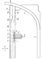
本発明の実施形態に係る車両用荷室構造の一例を示す図で、ボードの使用状態を示す要部概略側面図である。It is a figure which shows an example of the luggage compartment structure for a vehicle which concerns on embodiment of this invention, and is the schematic side view of the main part which shows the use state of a board. ボードをリアシートの背面に立て掛けたときの状態を示す要部概略側面図である。It is a schematic side view of a main part which shows the state when a board leans against the back of a rear seat. ボードをリアシートの背面に立て掛けたときの状態を示す背面図である。It is a rear view which shows the state when a board leans against the back of a rear seat. (a)は掛止部材をフック部材に掛止したときの状態を示す要部概略拡大背面図、(b)は掛止部材を保持部材に係合させたときの状態を示す要部概略拡大背面図である。(A) is a schematic enlarged rear view of the main part showing the state when the hook member is hooked on the hook member, and (b) is a schematic enlarged rear view of the main part showing the state when the hook member is engaged with the holding member. It is a rear view. ボードの使用状態を示す要部拡大概略背面図である。It is the enlarged schematic rear view of the main part which shows the use state of a board. ボードの使用状態を示す要部概略斜視図である。It is a schematic perspective view of the main part which shows the use state of a board. 図3の要部拡大図である。It is an enlarged view of the main part of FIG. 図7の要部拡大図である。It is an enlarged view of the main part of FIG. スライドボードに設けられた連結部材の設置状態を示す要部拡大斜視図である。It is an enlarged perspective view of the main part which shows the installation state of the connecting member provided on the slide board. 車室の側面に設けられた棚部の設置状態を示す要部拡大斜視図である。It is an enlarged perspective view of the main part which shows the installation state of the shelf part provided on the side surface of the passenger compartment. リアシートを前側に移動させたときのボードの状態を示す要部概略側面図である。It is a schematic side view of a main part which shows the state of a board when the rear seat is moved to the front side. リアシートを後側に移動させたときのボードの状態を示す要部概略側面図である。It is a schematic side view of the main part which shows the state of a board when the rear seat is moved to the rear side. 棚部に載置したトランクボードの載置状態を示す要部縦断面図である。It is a vertical cross-sectional view of the main part which shows the mounting state of the trunk board mounted on the shelf part.

以下、添付図面に基づき本発明の実施形態に係る車両用荷室構造の一例を説明する。
なお、図1または図2に示す車両1の進行方向を「F」、後退方向を「B」、「鉛直上方側を「U」、鉛直下方側を「D」、左側を「L」、右側を「R」として適宜説明する。また、シート連結部材65の前端部を中心として回動するボード3は、図1に示す水平状態にしたときの基端側を前側、先端側を後側として説明する。
Hereinafter, an example of a vehicle luggage compartment structure according to an embodiment of the present invention will be described with reference to the accompanying drawings.
The traveling direction of the vehicle 1 shown in FIG. 1 or 2 is "F", the backward direction is "B", the "vertically upper side is" U ", the vertically lower side is" D ", the left side is" L ", and the right side. Will be described as “R” as appropriate. Further, the board 3 that rotates about the front end portion of the seat connecting member 65 will be described with the base end side as the front side and the front end side as the rear side when the seat connecting member 65 is in the horizontal state.

≪車両≫
車両1は、車両1の後面に設けられた後部開口1aと、後部開口1aを開閉する扉(図示省略)と、車体後部に設けられた荷室2と、荷室2の前側に配置されたシート(例えば、リアシート6)と、荷室2に配置されたボード3と、ボード3を支持する棚部11と、を備えている。
≪Vehicle≫
The vehicle 1 is arranged at a rear opening 1a provided on the rear surface of the vehicle 1, a door for opening and closing the rear opening 1a (not shown), a luggage compartment 2 provided at the rear of the vehicle body, and a front side of the luggage compartment 2. It includes a seat (for example, a rear seat 6), a board 3 arranged in the luggage compartment 2, and a shelf portion 11 that supports the board 3.

なお、車両1は、図1に示すように、車体後部に荷室2、後部開口1a、扉(図示省略)、車室内壁22、シートを有するものであれば、形式、種類は特に限定されない。車両1は、例えば、ミニバン、ワンボックスタイプ、ハッチバック、ステーションワゴン、クーペタイプ等の自動車から成る。また、車両1は、1列シートでも、2列シート、3列シート等の複数列のシートを有する自動車でもよい。以下、ミニバンタイプの2列シートの自動車を例に挙げて説明する。 As shown in FIG. 1, the vehicle 1 is not particularly limited in type and type as long as it has a luggage compartment 2, a rear opening 1a, a door (not shown), a vehicle interior wall 22, and a seat at the rear of the vehicle body. .. The vehicle 1 includes, for example, a minivan, a one-box type, a hatchback, a station wagon, a coupe type, or the like. Further, the vehicle 1 may be a single-row seat or an automobile having a plurality of rows of seats such as a two-row seat and a three-row seat. Hereinafter, a minivan type two-row seat automobile will be described as an example.

≪車両用荷室構造≫
車両用荷室構造は、図1または図2に示すように、リアシート6と、荷室空間21を有する荷室2と、荷室空間21に配置されたボード3と、リアシート6に設けられたフック部材4と、ボード3に設けられた掛止部材5と、を備えて成る。
≪Vehicle luggage compartment structure≫
As shown in FIG. 1 or 2, the vehicle luggage compartment structure is provided on the rear seat 6, the luggage compartment 2 having the luggage compartment space 21, the board 3 arranged in the luggage compartment space 21, and the rear seat 6. It includes a hook member 4 and a hook member 5 provided on the board 3.

後部開口1aは、荷室2内に荷物を収納したり、荷室2内の荷物を取り出したりするためのドア開口部である。後部開口1aの下面1cは、荷室2の床面23に載置した荷物等が荷室2から落下しないように、床面23よりも高い位置に設けられている。後部開口1aの下面1cの中央部後側には、バックドア(図示省略)に設けたラッチ装置のラッチが係合するストライカ(図示省略)が設けられている。後部開口1aの下面1cは、例えば、平面視して略円弧状に形成されている(図6参照)。このため、バックドア(図示省略)は、横断面視して略円弧状に形成されて、全体が僅かに丸みを帯びた形状になっている。図1に示すように、後部開口1aの下面1cの上方のドア開口エリアD内において、後記するボード3のトランクボード32の後端部(後辺32k)が、バックドア(図示省略)に当接する手前のギリギリの位置まで伸びている。 The rear opening 1a is a door opening for storing luggage in the luggage compartment 2 and taking out the luggage in the luggage compartment 2. The lower surface 1c of the rear opening 1a is provided at a position higher than the floor surface 23 so that the luggage or the like placed on the floor surface 23 of the luggage compartment 2 does not fall from the luggage compartment 2. A striker (not shown) with which the latch of the latch device provided on the back door (not shown) engages is provided on the rear side of the center of the lower surface 1c of the rear opening 1a. The lower surface 1c of the rear opening 1a is formed in a substantially arc shape in a plan view, for example (see FIG. 6). For this reason, the back door (not shown) is formed in a substantially arc shape in a cross-sectional view, and has a slightly rounded shape as a whole. As shown in FIG. 1, in the door opening area D above the lower surface 1c of the rear opening 1a, the rear end portion (rear side 32k) of the trunk board 32 of the board 3 described later corresponds to the back door (not shown). It extends to the last minute position before it touches.

なお、扉(図示省略)は、後部開口1aを開閉可能なものであれば、どのようなタイプのドアでも構わない。扉(図示省略)は、例えば、跳ねた上げタイプのヒンジ式ドアから成る。 The door (not shown) may be any type of door as long as it can open and close the rear opening 1a. The door (not shown) comprises, for example, a flip-up type hinged door.

<荷室>
荷室2は、荷物を収納したり、積載したりする空間である。この荷室2は、車体後端部に設けられた後部開口1aと、客室の後端部に配置されたリアシート6との間に形成されている。荷室2は、リアシート6を前後方向に移動させることによって、荷室2の前後方向に長さを変えることが可能になっている。荷室2内の左右両側には、ボード3のトランクボード32を支持する棚部11を有する車室内壁22が形成されている。
<Luggage room>
The luggage compartment 2 is a space for storing and loading luggage. The luggage compartment 2 is formed between the rear opening 1a provided at the rear end of the vehicle body and the rear seat 6 arranged at the rear end of the passenger compartment. The length of the luggage compartment 2 can be changed in the front-rear direction of the luggage compartment 2 by moving the rear seat 6 in the front-rear direction. On both left and right sides of the luggage compartment 2, vehicle interior walls 22 having shelves 11 for supporting the trunk board 32 of the board 3 are formed.

図1に示すように、荷室空間21は、車両1のリアシート6の後方に設けられた荷室2内の荷物収納空間である。荷室空間21は、ボード3を、荷物を載置可能な載置位置の状態に配置した場合、ボード3によって上側荷室空間と、下側荷室空間と、に上下に区画される。 As shown in FIG. 1, the luggage compartment space 21 is a luggage storage space in the luggage compartment 2 provided behind the rear seat 6 of the vehicle 1. When the board 3 is arranged in a loading position where luggage can be placed, the luggage compartment space 21 is vertically divided into an upper luggage compartment space and a lower luggage compartment space by the board 3.

荷室2の床面23には、工具、スペアタイヤ、荷物等を床下収納する略直方体形状の荷物収納凹部を閉塞したり、荷物を積載したりする樹脂製のフロアボード24が配置されている。フロアボード24は、金属製平板部材から成るフロアパネル(図示省略)の上方に配置されている。 On the floor surface 23 of the luggage compartment 2, a resin floor board 24 for closing a substantially rectangular parallelepiped luggage storage recess for storing tools, spare tires, luggage, etc. under the floor and for loading luggage is arranged. .. The floor board 24 is arranged above a floor panel (not shown) made of a metal flat plate member.

<棚部>
図1、図2及び図11に示すように、棚部11は、トランクボード32を下側から支持する支持部である。図10に示すように、棚部11は、左右の車室内壁22から荷室2側(車内側)に膨出し、前後方向に水平に延設されている。棚部11の上面11fには、前端部に設けられた凹部11bと、凹部11bの後方に設けられた凸部または凹部11aと、が設けられている。
<Shelves>
As shown in FIGS. 1, 2 and 11, the shelf portion 11 is a support portion that supports the trunk board 32 from below. As shown in FIG. 10, the shelf portion 11 bulges from the left and right vehicle interior walls 22 to the luggage compartment 2 side (inside the vehicle) and extends horizontally in the front-rear direction. The upper surface 11f of the shelf portion 11 is provided with a concave portion 11b provided at the front end portion and a convex portion or a concave portion 11a provided behind the concave portion 11b.

図11に示すように、凸部または凹部11aは、トランクボード32を棚部11上に水平に載置した際に、トランクボード32の下面に形成した係合部32cが係合する部位である。凸部または凹部11aは、棚部11の上面11fに突出形成された平面視及び側面視して略台形に形成された突起から成る。なお、凸部または凹部11aと、係合部32cとは、互いに係合する凹凸関係であればよく、互いに凹凸関係を逆にした形状にしてもよい。 As shown in FIG. 11, the convex portion or the concave portion 11a is a portion where the engaging portion 32c formed on the lower surface of the trunk board 32 engages when the trunk board 32 is horizontally placed on the shelf portion 11. .. The convex portion or the concave portion 11a is composed of a protrusion formed on the upper surface 11f of the shelf portion 11 and formed in a substantially trapezoidal shape in a plan view and a side view. The convex portion or the concave portion 11a and the engaging portion 32c may have a concave-convex relationship that engages with each other, and may have a shape in which the concave-convex relationship is reversed.

図11に示すように、凹部11bは、上部を開口する略U字状の溝から成る。凹部11bは、ボード3をリアシート6の背面に立て掛けて、トランクボード32を掛止部材5でシートバック61のフック部材4に掛止する際に、トランクボード32の保持部32fを挿入して保持するための溝である。 As shown in FIG. 11, the recess 11b is composed of a substantially U-shaped groove that opens an upper portion. The recess 11b is held by inserting the holding portion 32f of the trunk board 32 when the board 3 is leaned against the back surface of the rear seat 6 and the trunk board 32 is hooked on the hook member 4 of the seat back 61 by the hooking member 5. It is a groove to do.

図10に示すように、凹部11bは、第1側壁11dと、底面11cと、第2側壁11eと、によって形成されている。
第1側壁11dは、棚部11の上面11fの前端から下方に伸びる凹部11bの後側内壁面である。
底面11cは、第1側壁11dの下端から前方に向かって伸びる内底面である。
第2側壁11eは、底面11cの前端から第1側壁11dに沿って上方に伸びる凹部11bの前側内壁面である。この第2側壁11eは、棚部11の上面11fよりも上方に伸びている。
As shown in FIG. 10, the recess 11b is formed by a first side wall 11d, a bottom surface 11c, and a second side wall 11e.
The first side wall 11d is a rear inner wall surface of a recess 11b extending downward from the front end of the upper surface 11f of the shelf portion 11.
The bottom surface 11c is an inner bottom surface extending forward from the lower end of the first side wall 11d.
The second side wall 11e is a front inner wall surface of the recess 11b extending upward along the first side wall 11d from the front end of the bottom surface 11c. The second side wall 11e extends upward from the upper surface 11f of the shelf portion 11.

<リアシート>
図1に示すように、リアシート6は、車室の後部に配置された座席である。リアシート6は、シートバック61と、シートクッション62と、傾動機構63と、スライド機構64と、シート連結部材65と、を備えている。リアシート6は、荷室2の前側に配置されて、棚部11の前方で前後方向にスライド可能に配置されている。リアシート6は、例えば、左右一対の座席から成る(図3参照)。
なお、リアシート6は、一つのベンチシートであってもよい。また、リアシート6は、荷室2の前側にあればよく、フロントシートであってもよい。
<Rear seat>
As shown in FIG. 1, the rear seat 6 is a seat arranged at the rear of the passenger compartment. The rear seat 6 includes a seat back 61, a seat cushion 62, a tilting mechanism 63, a slide mechanism 64, and a seat connecting member 65. The rear seat 6 is arranged on the front side of the luggage compartment 2 and is slidably arranged in the front-rear direction in front of the shelf portion 11. The rear seat 6 is composed of, for example, a pair of left and right seats (see FIG. 3).
The rear seat 6 may be one bench seat. Further, the rear seat 6 may be a front seat as long as it is on the front side of the luggage compartment 2.

シートバック61は、例えば、シートバック61の下端部を中心として前後方向に傾倒可能な可倒式のものから成る。シートバック61は、傾動機構63及びシートロック機構(図示省略)によって、適宜な角度に傾けてロックすることが可能になっている。図3に示すように、例えば、右側のリアシート6のシートバック61の背面上部には、後記するフック部材4が設けられている。そのフック部材4は、シートバック61の背面の車幅方向中央寄りの位置に設置されている。
なお、フック部材4は、左側のリアシート6のシートバック61に取り付けてあってもよく、また、左右の両方のリアシート6のシートバック61に取り付けてあってもよい。また、フック部材4の構成は、後で詳述する。
The seat back 61 is made of, for example, a foldable type that can be tilted in the front-rear direction about the lower end portion of the seat back 61. The seat back 61 can be locked by tilting it at an appropriate angle by the tilting mechanism 63 and the seat locking mechanism (not shown). As shown in FIG. 3, for example, a hook member 4 described later is provided on the upper back surface of the seat back 61 of the rear seat 6 on the right side. The hook member 4 is installed at a position closer to the center in the vehicle width direction on the back surface of the seat back 61.
The hook member 4 may be attached to the seat back 61 of the left rear seat 6, or may be attached to the seat back 61 of both the left and right rear seats 6. The configuration of the hook member 4 will be described in detail later.

図1に示すように、シートクッション62は、シートバック61の下端部に、前後方向に所定距離だけスライド移動可能に配置されている。 As shown in FIG. 1, the seat cushion 62 is arranged at the lower end of the seat back 61 so as to be slidable by a predetermined distance in the front-rear direction.

傾動機構63は、シートバック61を適宜な角度に調整してその角度に保持するための装置である。傾動機構63は、シートバック61の下端部と、シートクッション62の後端部との連結箇所に設けられている。なお、傾動機構63は、傾動機構63の操作部を操作することによって、シートバック61を後傾状態から直立状態にすることが可能なものであればよく、その構造は特に限定されない。また、傾動機構63は、なくてもよい。 The tilting mechanism 63 is a device for adjusting the seat back 61 to an appropriate angle and holding the seat back 61 at that angle. The tilting mechanism 63 is provided at a connecting portion between the lower end portion of the seat back 61 and the rear end portion of the seat cushion 62. The tilting mechanism 63 is not particularly limited as long as it can change the seat back 61 from the backward tilted state to the upright state by operating the operating portion of the tilting mechanism 63. Further, the tilting mechanism 63 may not be provided.

図1に示すように、リアシート6は、スライド機構64によって、前後方向に摺動させて前後方向の位置を調整できるようになっている。スライド機構64の後端部には、スライドボード31の先端部に設けた連結部材33のシート連結部材連結片33dに連結したシート連結部材65の前端部が連結されている。このため、シートクッション62は、前後方向に移動させれば、シート連結部材65及び連結部材33を介在してスライドボード31も前後方向に一緒に連動するように構成されている。 As shown in FIG. 1, the rear seat 6 is slid in the front-rear direction by the slide mechanism 64 so that the position in the front-rear direction can be adjusted. The front end of the seat connecting member 65 connected to the seat connecting member connecting piece 33d of the connecting member 33 provided at the tip of the slide board 31 is connected to the rear end of the slide mechanism 64. Therefore, when the seat cushion 62 is moved in the front-rear direction, the slide board 31 is also configured to interlock with the seat connecting member 65 and the connecting member 33 in the front-rear direction.

図1及び図2に示すように、シート連結部材65は、リアシート6とスライドボード31とを連結するための部材である。シート連結部材65は、シート連結部65aと、ボード連結部65bと、シート連結部材本体65cと、を有する金属製部材から成る。 As shown in FIGS. 1 and 2, the seat connecting member 65 is a member for connecting the rear seat 6 and the slide board 31. The seat connecting member 65 is composed of a metal member having a seat connecting portion 65a, a board connecting portion 65b, and a seat connecting member main body 65c.

シート連結部65aは、シートクッション62の後端部に、シートクッション62の後端部を中心として前後方向に回動自在に軸支されている。
ボード連結部65bは、略逆U字形状のシート連結部材本体65cにおいて、スライドボード31の連結部材33に着脱自在に連結される部位である。
シート連結部材本体65cは、前端側に設けられたシート連結部65aと、後部側に配置されたボード連結部65bと、を連結した金属製棒状部材から成る。
The seat connecting portion 65a is pivotally supported at the rear end portion of the seat cushion 62 so as to be rotatable in the front-rear direction around the rear end portion of the seat cushion 62.
The board connecting portion 65b is a portion of the substantially inverted U-shaped seat connecting member main body 65c that is detachably connected to the connecting member 33 of the slide board 31.
The seat connecting member main body 65c is composed of a metal rod-shaped member that connects a seat connecting portion 65a provided on the front end side and a board connecting portion 65b arranged on the rear end side.

<ボード>
図1及び図11に示すように、ボード3は、荷物を載置するための板状部材である。ボード3は、スライドボード31と、トランクボード32と、連結部材33(被連結部33c)と、掛止部材5(図2参照)と、を備えて構成されている。ボード3は、荷室空間21において、図1及び図11に示す荷物を載置可能な載置位置と、図2、図3及び図12に示すリアシート6の背面に配置される収納位置と、に保持可能である。図2に示すように、載置位置の状態に配置したボード3は、荷室空間21を上側の上部荷室空間と、下側の下部荷室空間と、に上下に区画して、荷室2を二つの部屋にする仕切り部材の機能を有している。
<Board>
As shown in FIGS. 1 and 11, the board 3 is a plate-shaped member on which luggage is placed. The board 3 includes a slide board 31, a trunk board 32, a connecting member 33 (connected portion 33c), and a hooking member 5 (see FIG. 2). The board 3 has a loading position in the luggage compartment space 21 on which the luggage shown in FIGS. 1 and 11 can be placed, and a storage position arranged on the back surface of the rear seat 6 shown in FIGS. 2, 3 and 12. Can be held in. As shown in FIG. 2, in the board 3 arranged in the mounting position, the luggage compartment space 21 is divided into an upper luggage compartment space on the upper side and a lower luggage compartment space on the lower side. It has the function of a partition member that makes 2 into two rooms.

<スライドボード>
図11及び図12に示すように、スライドボード31は、リアシート6と一緒に前後方向にスライド可能な平面視して略矩形の樹脂製の厚板状部材である。スライドボード31の前端部は、連結部材33及びシート連結部材65を介在してリアシート6に着脱可能に連結されている。このため、スライドボード31は、リアシート6を前方向にスライド移動させた際に、リアシート6とスライドボード31の前端との間に、大きな隙間Sができるのを抑制して、隙間Sから荷物が落下するのを防止することができる。つまり、その隙間Sは、スライドボード31がリアシート6と一緒に前後方向に連動することで、シートバック61を傾動させない限り、変化しないように構成されている。
<Slide board>
As shown in FIGS. 11 and 12, the slide board 31 is a resin thick plate-like member that is slidable in the front-rear direction together with the rear seat 6 and is substantially rectangular in plan view. The front end portion of the slide board 31 is detachably connected to the rear seat 6 via a connecting member 33 and a seat connecting member 65. Therefore, the slide board 31 suppresses the formation of a large gap S between the rear seat 6 and the front end of the slide board 31 when the rear seat 6 is slid forward, and the luggage can be removed from the gap S. It can be prevented from falling. That is, the gap S is configured so as not to change unless the seat back 61 is tilted by the slide board 31 interlocking with the rear seat 6 in the front-rear direction.

スライドボード31の下側の左右前端部には、リアシート6に連結するための連結部材33が固定されている。また、スライドボード31には、下面から下方に伸びると共に後方に開口する開口部を備えた被連結部33c(連結部材33)が設けられている。スライドボード31は、トランクボード32を左右の車室内壁22の棚部11間に掛け渡して配置した際に、スライドボード31の後部が、トランクボード32の上面に載置される。 Connecting members 33 for connecting to the rear seat 6 are fixed to the left and right front ends on the lower side of the slide board 31. Further, the slide board 31 is provided with a connected portion 33c (connecting member 33) having an opening extending downward from the lower surface and opening rearward. When the trunk board 32 is placed between the shelves 11 of the left and right passenger compartment walls 22, the rear portion of the slide board 31 is placed on the upper surface of the trunk board 32.

<トランクボード>
トランクボード32は、スライドボード31の下側に配置されて、車室の側面1bに支持させることが可能な平面視して略四角形の樹脂製の厚板部材から成る。トランクボード32は、連結部32aと、前延部32bと、係合部32cと、前側両端部32dと、後延部32eと、保持部32fと、一般部32gと、傾斜部32hと、側辺32iと、角辺32jと、後辺32kと、コーナー部32mと、開口領域部32nと、を有している。
<Trunk board>
The trunk board 32 is arranged under the slide board 31 and is made of a resin thick plate member which is substantially quadrangular in plan view and can be supported on the side surface 1b of the vehicle interior. The trunk board 32 includes a connecting portion 32a, a front extending portion 32b, an engaging portion 32c, front both ends 32d, a rear extending portion 32e, a holding portion 32f, a general portion 32g, an inclined portion 32h, and a side. It has a side 32i, a corner side 32j, a rear side 32k, a corner portion 32m, and an opening region portion 32n.

図1に示すように、トランクボード32は、車室の側面1bに設けられた棚部11の上方に水平に載置した載置位置の状態の場合、後辺32kが、後部開口1aの下面1cの上方に位置するように配置される。 As shown in FIG. 1, when the trunk board 32 is placed horizontally above the shelf 11 provided on the side surface 1b of the passenger compartment, the rear side 32k is the lower surface of the rear opening 1a. It is arranged so as to be located above 1c.

図3及び図7に示すように、トランクボード32の下面の後側には、トランクボード32をリアシート6の背面に立て掛けた状態にした際に、フック部材4のフック41に掛止される掛止部材5を固定した保持部材7が設けられている。トランクボード32は、リアシート6の背面に立て掛ける収納位置の状態の場合、図2または図13に示すように、左右の保持部32fを棚部11の凹部11bに挿入した状態に配置される。トランクボード32は、凹部11bの底面11cに前側両端部32dを当接させてトランクボード32を保持した際に、凹部11bの底面11cよりも前延部32bの方が下方に位置している。 As shown in FIGS. 3 and 7, a hook 41 of the hook member 4 is hooked on the rear side of the lower surface of the trunk board 32 when the trunk board 32 is leaned against the back surface of the rear seat 6. A holding member 7 to which the stop member 5 is fixed is provided. The trunk board 32 is arranged in a state where the left and right holding portions 32f are inserted into the recesses 11b of the shelf portion 11 as shown in FIG. 2 or 13 in the state of the storage position leaning against the back surface of the rear seat 6. When the front end portions 32d of the trunk board 32 are brought into contact with the bottom surface 11c of the recess 11b to hold the trunk board 32, the front extension portion 32b is located below the bottom surface 11c of the recess 11b.

図11また図12に示すように、連結部32aは、リアシート6、シート連結部材65、連結部材33及びスライドボード31が後側に移動した際に、スライドボード31に固定されたトランクボード連結片33bの被連結部33cに連結される箇所である。図7及び図8に示すように、連結部32aは、トランクボード32の前端(基端)の前側両端部32d寄りの位置に形成されている。 As shown in FIGS. 11 and 12, the connecting portion 32a is a trunk board connecting piece fixed to the slide board 31 when the rear seat 6, the seat connecting member 65, the connecting member 33, and the slide board 31 move to the rear side. This is a portion connected to the connected portion 33c of 33b. As shown in FIGS. 7 and 8, the connecting portion 32a is formed at a position closer to both front end portions 32d of the front end (base end) of the trunk board 32.

前延部32bは、トランクボード32をリアシート6の背面に立て掛けた際に、連結部32aからさらに前方(下側)に延設されて重心の位置を低くすることで、トランクボード32を立て掛けた状態を安定化させている。図7及び図8に示すように、前延部32bは、ボード3を水平に配置した載置位置の状態のトランクボード32において、連結部32aよりも前方に向かって伸びて形成されている。この前延部32bは、図2に示すように、凹部11bの底面11cに前側両端部32dを当接させてトランクボード32を保持している際に、底面11cよりも下方に位置するように配置される。 When the trunk board 32 was leaned against the back surface of the rear seat 6, the front extension portion 32b was extended further forward (lower side) from the connecting portion 32a to lower the position of the center of gravity, thereby leaning the trunk board 32. The state is stabilized. As shown in FIGS. 7 and 8, the front extension portion 32b is formed so as to extend forward from the connecting portion 32a in the trunk board 32 in the mounted position in which the board 3 is arranged horizontally. As shown in FIG. 2, the front extension portion 32b is positioned below the bottom surface 11c when the front end portions 32d are brought into contact with the bottom surface 11c of the recess 11b to hold the trunk board 32. Be placed.

図11に示すように、係合部32cは、トランクボード32を棚部11上に載置した場合に、棚部11の上面11fに形成された凸部または凹部11aに係合してトランクボード32を支持する箇所である。係合部32cは、ボード3を水平に配置した載置位置の状態のトランクボード32において、トランクボード32の下面の左右端部中央に切欠形成された底面視及び側面視して略台形形状の溝から成る(図8参照)。 As shown in FIG. 11, when the trunk board 32 is placed on the shelf portion 11, the engaging portion 32c engages with the convex portion or the concave portion 11a formed on the upper surface 11f of the shelf portion 11 to engage with the trunk board. This is a place that supports 32. The engaging portion 32c has a substantially trapezoidal shape when viewed from the bottom and side surfaces, which is notched in the center of the left and right ends of the lower surface of the trunk board 32 in the trunk board 32 in the mounted position in which the board 3 is horizontally arranged. It consists of a groove (see FIG. 8).

図7及び図8に示すように、前側両端部32dは、トランクボード32の車幅方向の両端部である。
後延部32eは、連結部32aの車幅方向端部から後方(先端側)に向かって伸びて形成された部位である。
As shown in FIGS. 7 and 8, the front end portions 32d are both end portions of the trunk board 32 in the vehicle width direction.
The rear extension portion 32e is a portion formed by extending from the end portion of the connecting portion 32a in the vehicle width direction toward the rear (tip side).

図2または図13に示すように、保持部32fは、トランクボード32をリアシート6の背面に立て掛けた収納位置の状態の際に、棚部11の凹部11bに挿入されて保持される箇所である。保持部32fは、凹部11bに係合させた場合、凹部11bの底面11cに当接した状態に配置される。図13に示すように、保持部32fは、後延部32eから車幅方向外側に向かって伸びて形成されている。 As shown in FIG. 2 or 13, the holding portion 32f is a portion that is inserted and held in the recess 11b of the shelf portion 11 when the trunk board 32 is in the storage position leaning against the back surface of the rear seat 6. .. When the holding portion 32f is engaged with the recess 11b, the holding portion 32f is arranged in a state of being in contact with the bottom surface 11c of the recess 11b. As shown in FIG. 13, the holding portion 32f is formed so as to extend outward in the vehicle width direction from the rear extension portion 32e.

図5〜図7に示すように、一般部32gは、トランクボード32において、略水平方向に延びる平らな箇所である。一般部32gの下面には、掛止部材5を収容する収容凹部71b(図7参照)が上方に向かって凹んだ形状で設けられている。 As shown in FIGS. 5 to 7, the general portion 32g is a flat portion extending in a substantially horizontal direction on the trunk board 32. On the lower surface of the general portion 32g, a housing recess 71b (see FIG. 7) for accommodating the hooking member 5 is provided in a shape recessed upward.

傾斜部32hは、一般部32gから後端に向かって上方に傾斜している箇所である(図11参照)。図1に示すように、傾斜部32hの少なくとも一部は、車幅方向から見て後部開口1aの下面1cの上方に位置する開口領域部32nを有している。図3に示すように、傾斜部32hは、後辺32kに沿って平行に形成されて、角辺32jに沿って平行に形成されない。 The inclined portion 32h is a portion inclined upward from the general portion 32g toward the rear end (see FIG. 11). As shown in FIG. 1, at least a part of the inclined portion 32h has an opening region portion 32n located above the lower surface 1c of the rear opening 1a when viewed from the vehicle width direction. As shown in FIG. 3, the inclined portion 32h is formed in parallel along the rear side 32k, and is not formed in parallel along the corner side 32j.

側辺32iは、車幅方向に長い略六角形のトランクボード32の左右の辺である。側辺32iは、荷室2の側面1bに沿って伸びている(図6参照)。 The side sides 32i are the left and right sides of a substantially hexagonal trunk board 32 that is long in the vehicle width direction. The side side 32i extends along the side surface 1b of the luggage compartment 2 (see FIG. 6).

角辺32jは、略六角形のトランクボード32の車幅方向の後端部に斜めの辺を形成する箇所である。角辺32jは、側辺32iから後方に向かうに連れて車幅方向中央に向かって傾斜して形成されている。 The square side 32j is a portion where an oblique side is formed at the rear end portion of the substantially hexagonal trunk board 32 in the vehicle width direction. The corner side 32j is formed so as to be inclined toward the center in the vehicle width direction from the side side 32i toward the rear.

後辺32kは、左右の角辺32jの後端から車幅方向に伸びる辺である。図1に示すように、後辺32kは、トランクボード32を左右の棚部11間に架設するように、水平に配置した際に、後部開口1aの下面1cの上方に配置される。 The rear side 32k is a side extending in the vehicle width direction from the rear ends of the left and right corner sides 32j. As shown in FIG. 1, the rear side 32k is arranged above the lower surface 1c of the rear opening 1a when the trunk board 32 is arranged horizontally so as to be laid between the left and right shelves 11.

図7に示すように、コーナー部32mは、平らな一般部32gと、傾斜している傾斜部32hとが交わる稜線である。コーナー部32mは、後辺32kに沿って平行に車幅方向に延設されている。稜線によって補強されたコーナー部32mには、保持部材本体71が取り付けられている。 As shown in FIG. 7, the corner portion 32m is a ridgeline where a flat general portion 32g and an inclined inclined portion 32h intersect. The corner portion 32m extends parallel to the rear side 32k in the vehicle width direction. A holding member main body 71 is attached to the corner portion 32 m reinforced by the ridge line.

開口領域部32nは、図1または図11に示すように、トランクボード32において、後部開口1aの下面1cの上方のドア開口エリアD内まで伸びて配置されている箇所である。このため、開口領域部32nは、フロアボード24や、荷室2の床面23よりも車体後方に伸びている。 As shown in FIG. 1 or 11, the opening region portion 32n is a portion of the trunk board 32 that extends into the door opening area D above the lower surface 1c of the rear opening 1a. Therefore, the opening region portion 32n extends to the rear of the vehicle body with respect to the floor board 24 and the floor surface 23 of the luggage compartment 2.

<連結部材>
図8または図9に示すように、連結部材33は、スライドボード31をトランクボード32及びシート連結部材65に着脱自在に連結するための部材である。連結部材33は、スライドボード31の左右前端部に固定された左右一対の金属製部材から成る。連結部材33は、連結部材本体33aと、トランクボード連結片33bと、被連結部33cと、シート連結部材連結片33dと、を有している。連結部材33は、複数の固定具34によってスライドボード31の下面の前側の左右端部にそれぞれ固定されている。
<Connecting member>
As shown in FIG. 8 or 9, the connecting member 33 is a member for detachably connecting the slide board 31 to the trunk board 32 and the seat connecting member 65. The connecting member 33 is composed of a pair of left and right metal members fixed to the left and right front ends of the slide board 31. The connecting member 33 includes a connecting member main body 33a, a trunk board connecting piece 33b, a connected portion 33c, and a seat connecting member connecting piece 33d. The connecting member 33 is fixed to each of the left and right ends on the front side of the lower surface of the slide board 31 by a plurality of fixtures 34.

連結部材本体33aは、スライドボード31に締結具等の固定具34によって固定される部位である。連結部材本体33aは、車幅方向に延設された略矩形の平板状に形成されている。
図8または図9に示すように、トランクボード連結片33bは、連結部材本体33aの車幅方向中央側前端部からトランクボード32側に突出するように折曲形成された側面視して略L字形状の突出片から成る。図11及び図12に示すように、トランクボード連結片33bと、スライドボード31との間には、トランクボード32の連結部32aが係合される被連結部33cが形成されている。トランクボード連結片33bの先端部は、トランクボード32がスムーズに係合できるように斜め下方向に拡開するように折曲形成されている。
The connecting member main body 33a is a portion fixed to the slide board 31 by a fixing tool 34 such as a fastener. The connecting member main body 33a is formed in a substantially rectangular flat plate shape extending in the vehicle width direction.
As shown in FIG. 8 or 9, the trunk board connecting piece 33b is formed to be bent so as to project from the front end portion on the vehicle width direction center side of the connecting member main body 33a toward the trunk board 32 side. It consists of a letter-shaped protrusion. As shown in FIGS. 11 and 12, a connected portion 33c to which the connecting portion 32a of the trunk board 32 is engaged is formed between the trunk board connecting piece 33b and the slide board 31. The tip of the trunk board connecting piece 33b is bent so as to expand diagonally downward so that the trunk board 32 can be smoothly engaged.

<被連結部>
被連結部33cは、トランクボード32の左右前端部の連結部32aが着脱自在に係合されて、連結部32aを支持する部位である。被連結部33cは、側面視して略L字状のトランクボード連結片33bと、スライドボード31の下面と、によって形成された横溝形状の空間から成る。被連結部33cは、スライドボード31の下面から下方に伸びると共に、後方に開口する開口部を備えている。図4及び図5に示すように、被連結部33cは、スライドボード31が後方向(矢印b方向)にスライド移動したときに、連結部32aに連結される。
<Connected part>
The connected portion 33c is a portion where the connecting portions 32a at the left and right front ends of the trunk board 32 are detachably engaged with each other to support the connecting portion 32a. The connected portion 33c is composed of a lateral groove-shaped space formed by a trunk board connecting piece 33b having a substantially L-shape when viewed from the side and a lower surface of the slide board 31. The connected portion 33c is provided with an opening extending downward from the lower surface of the slide board 31 and opening rearward. As shown in FIGS. 4 and 5, the connected portion 33c is connected to the connecting portion 32a when the slide board 31 slides in the rear direction (direction of arrow b).

図11または図12に示すように、シート連結部材連結片33dは、連結部材本体33aの車幅方向外側前端部からリアシート6側に突出形成された突出片から成る。シート連結部材連結片33dは、シートクッション62の後端部に設けられたシート連結部材65のボード連結部65bを、着脱自在に連結する。図9または図11に示すように、シート連結部材連結片33dは、ボード連結部65bが係合される係合部33d1と、係合部33d1の先端側に形成された係止部33d2と、を連続形成して成る。
係合部33d1は、側面視して略J字状に形成された舌片から成る。係止部33d2は、トランクボード32がスムーズに係合できるように、係合部33d1の先端から下方向に拡開するように略湾曲状に曲げて形成されている。
As shown in FIGS. 11 or 12, the seat connecting member connecting piece 33d is composed of a protruding piece formed so as to project from the outer front end portion of the connecting member main body 33a in the vehicle width direction toward the rear seat 6. The seat connecting member connecting piece 33d detachably connects the board connecting portion 65b of the seat connecting member 65 provided at the rear end portion of the seat cushion 62. As shown in FIG. 9 or 11, the seat connecting member connecting piece 33d includes an engaging portion 33d1 to which the board connecting portion 65b is engaged, and a locking portion 33d2 formed on the tip end side of the engaging portion 33d1. Is continuously formed.
The engaging portion 33d1 is composed of a tongue piece formed in a substantially J shape when viewed from the side. The locking portion 33d2 is formed by being bent in a substantially curved shape so as to expand downward from the tip of the engaging portion 33d1 so that the trunk board 32 can be smoothly engaged.

<フック部材>
図3及び図4(a)、(b)に示すように、フック部材4は、掛止部材5を掛止させることによって、リアシート6の背面に立て掛けたボード3を立て掛けた状態に保持するための掛止具である。このほか、フック部材4は、レジ袋(「取手付きゴミ袋」、「コンビニ袋」ともいう。)取手付きバッグ等を掛止する掛止具としても使用可能である。フック部材4は、リアシート6の背面において、図1に示すような載置位置の状態のボード3よりも上方の位置に設けられている。さらに、詳述すると、フック部材4は、図2に示すように、ボード3をリアシート6の背面に配置した収納位置の状態で、掛止部材5を掛止させることが可能な位置に設置されている。フック部材4は、車幅方向において、前延部32bの直上に設けられている。図4(a)、(b)に示すように、フック部材4は、側面視して略J字形状に形成されたフック41と、フック41をシートバック61の背面に固定するための固定枠42と、を備えて構成されている。
<Hook member>
As shown in FIGS. 3 and 4 (a) and 4 (b), the hook member 4 holds the board 3 leaning against the back surface of the rear seat 6 in a leaning state by hooking the hook member 5. It is a hooking tool. In addition, the hook member 4 can also be used as a hooking tool for hanging a plastic shopping bag (also referred to as a "garbage bag with a handle" or a "convenience store bag") or a bag with a handle. The hook member 4 is provided on the back surface of the rear seat 6 at a position above the board 3 in the mounting position as shown in FIG. Further, in detail, as shown in FIG. 2, the hook member 4 is installed at a position where the hook member 5 can be hooked in the state of the storage position where the board 3 is arranged on the back surface of the rear seat 6. ing. The hook member 4 is provided directly above the front extension portion 32b in the vehicle width direction. As shown in FIGS. 4A and 4B, the hook member 4 includes a hook 41 formed in a substantially J shape when viewed from the side, and a fixing frame for fixing the hook 41 to the back surface of the seat back 61. 42, and is configured.

<掛止部材>
図3に示すように、掛止部材5は、フック部材4に引っ掛け可能な可撓性の部材によって形成されている。掛止部材5は、例えば、略U字状に折り曲げた線状部材の両端部をボード3の中央部の右寄りの位置に設けられている。図4(a)、(b)に示すように、掛止部材5は、フック部材4に直接引っ掛けて掛止するワイヤ51によって形成されている。掛止部材5の基端部は、固定具72によってトランクボード32の下面に固定された保持部材7に固定されている。
<Hooking member>
As shown in FIG. 3, the hooking member 5 is formed of a flexible member that can be hooked on the hook member 4. The hooking member 5 is provided, for example, at both ends of a linear member bent in a substantially U shape at a position to the right of the central portion of the board 3. As shown in FIGS. 4A and 4B, the hooking member 5 is formed by a wire 51 that directly hooks and hooks the hook member 4. The base end portion of the hook member 5 is fixed to the holding member 7 fixed to the lower surface of the trunk board 32 by the fixture 72.

ワイヤ51は、ある程度自由に曲げることが可能であって、ボード3を引っ張り上げることが可能な引張力を有する部材から成る。ワイヤ51は、1本から成るものであっても、複数本を撚ったケーブル状のものであってもよい。ワイヤ51は、例えば、線状、ロープ状、紐状、ワイヤ状、鎖等の樹脂製、金属製、あるいは、繊維製の部材から成る。 The wire 51 is made of a member having a tensile force that can be bent to some extent and can pull up the board 3. The wire 51 may be composed of one wire or may be in the form of a cable in which a plurality of wires are twisted. The wire 51 is made of, for example, a member made of resin, metal, or fiber such as a linear, rope, string, wire, or chain.

<保持部材>
図4(a)、(b)に示すように、保持部材7は、掛止部材5の基端部を保持するための金属製または樹脂製のブラケットである。保持部材7は、掛止部材固定部71aと、収容凹部71bと、開口部71cと、を有する保持部材本体71から成る。図7に示すように、保持部材7は、一般部32gと傾斜部32hとの間に形成されたコーナー部32mに設けられている。
<Holding member>
As shown in FIGS. 4A and 4B, the holding member 7 is a metal or resin bracket for holding the base end portion of the hooking member 5. The holding member 7 is composed of a holding member main body 71 having a hooking member fixing portion 71a, a housing recess 71b, and an opening 71c. As shown in FIG. 7, the holding member 7 is provided at a corner portion 32m formed between the general portion 32g and the inclined portion 32h.

図4(a)、(b)に示すように、保持部材本体71は、複数の固定具72によってトランクボード32に固定された横長の矩形の平板部材から成る。
掛止部材固定部71aは、略U字状に曲げたワイヤ51の両側基端部を固定する固定部である。掛止部材固定部71aは、保持部材本体71に一体形成されている。
As shown in FIGS. 4A and 4B, the holding member main body 71 is composed of a horizontally long rectangular flat plate member fixed to the trunk board 32 by a plurality of fixtures 72.
The hook member fixing portion 71a is a fixing portion for fixing both side base ends of the wire 51 bent in a substantially U shape. The hooking member fixing portion 71a is integrally formed with the holding member main body 71.

図4(b)に示すように、収容凹部71bは、U字状の掛止部材5の先端側部位を、ブラつかないように収容する保持部である。収容凹部71bは、平面視してL字状に折曲形成された2つの突出片を対向配置して、U字状のワイヤ51の先端側部位を挿入することが可能な略筒状(略C字状)の空間から成る。収容凹部71bは、保持部材本体71に一体形成されている。図5または図7に示すように、収容凹部71bの上面は、トランクボード32の傾斜部32hの下面と交差する位置まで延びている。 As shown in FIG. 4B, the accommodating recess 71b is a holding portion for accommodating the tip end side portion of the U-shaped hooking member 5 without blurring. The accommodating recess 71b has a substantially tubular shape (substantially) in which two projecting pieces formed in an L shape in a plan view are arranged to face each other and a portion on the tip end side of the U-shaped wire 51 can be inserted. It consists of a C-shaped space. The accommodating recess 71b is integrally formed with the holding member main body 71. As shown in FIG. 5 or 7, the upper surface of the accommodating recess 71b extends to a position where it intersects the lower surface of the inclined portion 32h of the trunk board 32.

開口部71cは、略U字状のワイヤ51の先端側部位を挿入して保持する収容凹部71bの開口端部である。開口部71cは、トランクボード32を棚部11上の載置した際に、開口縁が後方向側を向くように開口している。 The opening 71c is an opening end of a housing recess 71b for inserting and holding a portion on the tip end side of a substantially U-shaped wire 51. The opening 71c is opened so that the opening edge faces the rear side when the trunk board 32 is placed on the shelf 11.

≪車両用荷室構造の作用≫
次に、図1〜図13を参照して本発明の実施形態に係る車両用荷室構造の作用を説明する。
≪Action of luggage compartment structure for vehicles≫
Next, the operation of the vehicle luggage compartment structure according to the embodiment of the present invention will be described with reference to FIGS. 1 to 13.

ボード3の上面に荷物を載置する場合は、図1に示すように、トランクボード32を棚部11の上に載置し、トランクボード32の上にスライドボード31を載置して、ボード3を荷室空間21内に水平に配置する。
この場合、ボード3は、図11に示すように、トランクボード32の下面の係合部32cが凸部または凹部11aに係合され、スライドボード31の前端部の連結部材33がリアシート6のシート連結部材65に連結されて保持されている。このため、ボード3は、車両1が走行中であっても、安定した状態で、荷室2内に配置することができる。
When the luggage is placed on the upper surface of the board 3, the trunk board 32 is placed on the shelf 11 and the slide board 31 is placed on the trunk board 32 as shown in FIG. 3 is arranged horizontally in the luggage compartment space 21.
In this case, as shown in FIG. 11, in the board 3, the engaging portion 32c on the lower surface of the trunk board 32 is engaged with the convex portion or the concave portion 11a, and the connecting member 33 at the front end portion of the slide board 31 is the seat of the rear seat 6. It is connected to and held by the connecting member 65. Therefore, the board 3 can be arranged in the luggage compartment 2 in a stable state even when the vehicle 1 is traveling.

トランクボード32の後端部の開口領域部32nは、図1または図11に示すように、後部開口1aの下面1cの上方に配置されて、荷室2内のフロアボード24や床面23よりも車体後方に伸びて配置されている。このため、荷物を載置するボード3の荷物載置面の面積を広げて、荷物の積載量を増やすことができる。また、トランクボード32の後端部に形成した傾斜部32hは、ボード3上に載置した荷物が傾斜部32hよりも後方に移動するのを規制することができる。 As shown in FIG. 1 or 11, the opening region portion 32n at the rear end of the trunk board 32 is arranged above the lower surface 1c of the rear opening 1a and is located above the floor board 24 and the floor surface 23 in the luggage compartment 2. Is also extended to the rear of the car body. Therefore, the area of the luggage loading surface of the board 3 on which the luggage is placed can be increased to increase the load capacity of the luggage. Further, the inclined portion 32h formed at the rear end portion of the trunk board 32 can regulate the movement of the luggage placed on the board 3 behind the inclined portion 32h.

荷室空間21は、ボード3が荷物を載置可能な水平な載置位置の状態に配置されている場合、図1に示すように、ボード3によって、上側と、下側との二つの空間に区画される。このため、荷物は、ボード3上と、ボード3の下側のフロアボード24上と、の二か所に載置することが可能である。 When the board 3 is arranged in a horizontal loading position where luggage can be placed, the luggage compartment space 21 has two spaces, an upper side and a lower side, depending on the board 3, as shown in FIG. It is partitioned into. Therefore, the luggage can be placed in two places, one on the board 3 and the other on the floor board 24 below the board 3.

この状態で、図11に示すように、リアシート6を前方向(矢印a方向)に移動させる。すると、スライドボード31が、連結部材33及びシート連結部材65を介在してリアシート6に引かれて、トランクボード32上を前方向に摺動する。このように、スライドボード31は、リアシート6と一緒に移動するので、シートバック61とスライドボード31との間の隙間Sが広がるのを抑制することができる。このため、隙間Sが広がって、隙間Sから荷物が落下するのを規制することができる。 In this state, as shown in FIG. 11, the rear seat 6 is moved in the forward direction (direction of arrow a). Then, the slide board 31 is pulled by the rear seat 6 via the connecting member 33 and the seat connecting member 65, and slides forward on the trunk board 32. In this way, since the slide board 31 moves together with the rear seat 6, it is possible to suppress the widening of the gap S between the seat back 61 and the slide board 31. Therefore, it is possible to prevent the gap S from widening and the load from falling from the gap S.

図12に示すように、リアシート6を後方向(矢印b方向)に移動させると、スライドボード31が、シート連結部材65及び連結部材33を介在してリアシート6に押されて、トランクボード32上の後方向に摺動する。このように、スライドボード31は、リアシート6を後退させたときも一緒に移動するので、シートバック61とスライドボード31との間の隙間Sが広がるのを抑制することができる。 As shown in FIG. 12, when the rear seat 6 is moved in the rear direction (direction of arrow b), the slide board 31 is pushed by the rear seat 6 via the seat connecting member 65 and the connecting member 33, and is pushed on the trunk board 32. It slides backwards. In this way, since the slide board 31 moves together even when the rear seat 6 is retracted, it is possible to suppress the widening of the gap S between the seat back 61 and the slide board 31.

ボード3を使用しない場合は、図2に示すように、まず、スライドボード31を、シート連結部65aを中心として前方向に回動させて、シートバック61の背面に立て掛ける。次に、トランクボード32の両端の保持部32fを、左右の棚部11の凹部11bに挿入して支持させる。続いて、トランクボード32に固定された掛止部材5をフック部材4に掛止する。このとき、掛止部材5は、トランクボード32の後端が後部開口1aの位置に配置されているので、ボード3を持ち上げるのに使用するストラップとして利用できるため、掛止作業が行い易い。 When the board 3 is not used, first, as shown in FIG. 2, the slide board 31 is rotated forward about the seat connecting portion 65a and leaned against the back surface of the seat back 61. Next, the holding portions 32f at both ends of the trunk board 32 are inserted into the recesses 11b of the left and right shelf portions 11 to support them. Subsequently, the hook member 5 fixed to the trunk board 32 is hooked to the hook member 4. At this time, since the rear end of the trunk board 32 is arranged at the position of the rear opening 1a, the hooking member 5 can be used as a strap used for lifting the board 3, so that the hooking work can be easily performed.

このように、トランクボード32は、棚部11の凹部11bに係合させることと、掛止部材5をフック部材4に掛止したことによって、安定した状態に車体に支持することができる。連結部材33及びシート連結部材65によってリアシート6に連結されているスライドボード31は、上端部がトランクボード32によって支えられているため、ガタつくことなく支持される。このようにすると、荷室2は、上下方向に広い荷室空間21となるので、大きな荷物をフロアボード24上に載置することが可能となる。 In this way, the trunk board 32 can be supported on the vehicle body in a stable state by engaging the recess 11b of the shelf portion 11 and hooking the hook member 5 on the hook member 4. Since the upper end of the slide board 31 connected to the rear seat 6 by the connecting member 33 and the seat connecting member 65 is supported by the trunk board 32, the slide board 31 is supported without rattling. In this way, the luggage compartment 2 becomes a large luggage compartment space 21 in the vertical direction, so that a large luggage can be placed on the floor board 24.

このように、本発明の車両用荷室構造は、図1または図2に示すように、車両1の後部に設けられた荷室2と、車両1の後面に設けられ荷室2と連通する後部開口1aと、荷室2を上下に仕切るトランクボード32と、を備えた車両用荷室構造において、後部開口1aの下面1cは、荷室2の床面23よりも高い位置に設けられ、トランクボード32は、略水平方向に延びる一般部32gと、一般部32gから後端に向かって上方に傾斜する傾斜部32hと、を備え、傾斜部32hの少なくとも一部は、車幅方向から見て後部開口1aの下面1cの上方に位置する開口領域部32nを有している。 As described above, as shown in FIG. 1 or 2, the luggage compartment structure for a vehicle of the present invention communicates with the luggage compartment 2 provided at the rear of the vehicle 1 and the luggage compartment 2 provided at the rear surface of the vehicle 1. In a vehicle luggage compartment structure including a rear opening 1a and a trunk board 32 that partitions the luggage compartment 2 vertically, the lower surface 1c of the rear opening 1a is provided at a position higher than the floor surface 23 of the luggage compartment 2. The trunk board 32 includes a general portion 32g extending in a substantially horizontal direction and an inclined portion 32h inclined upward from the general portion 32g toward the rear end, and at least a part of the inclined portion 32h is viewed from the vehicle width direction. It has an opening region portion 32n located above the lower surface 1c of the rear opening 1a.

これにより、トランクボード32は、傾斜部32hの少なくとも一部が、車幅方向から見て後部開口1aの下面1cの上方に位置する開口領域部32nを有していることで、水平に延びる一般部32gをより広くすることができる。このため、ボード3上に載置する荷物の積載量を増加させることができる。また、車両1の後部開口1aの下面1cは、荷室2の床面23よりも高い位置に設けられているので、荷室2の床面23に載置した荷物が後部開口1aよりも車体後方側に移動するのを抑制することができる。このため、荷物が、後部開口1aから落下するのを防止することができる。また、その高くなった後部開口1aの下面1cの上方には、上方に傾斜して傾斜部32hが位置している。このため、傾斜部32hは、荷室2の下側荷物室の開口を拡開するように形成するので、トランクボード32の下の荷室2の床面23上に向けて荷物を入れ易くすることができる。その結果、荷室に荷物を出し入れする際の作業性を向上させることができる。 As a result, the trunk board 32 generally extends horizontally because at least a part of the inclined portion 32h has an opening region portion 32n located above the lower surface 1c of the rear opening 1a when viewed from the vehicle width direction. The portion 32g can be made wider. Therefore, the load capacity of the luggage to be placed on the board 3 can be increased. Further, since the lower surface 1c of the rear opening 1a of the vehicle 1 is provided at a position higher than the floor surface 23 of the luggage compartment 2, the luggage placed on the floor surface 23 of the luggage compartment 2 is a vehicle body higher than the rear opening 1a. It is possible to suppress the movement to the rear side. Therefore, it is possible to prevent the luggage from falling from the rear opening 1a. Further, above the lower surface 1c of the raised rear opening 1a, an inclined portion 32h is located so as to be inclined upward. Therefore, since the inclined portion 32h is formed so as to widen the opening of the lower luggage compartment of the luggage compartment 2, it is easy to put the luggage toward the floor surface 23 of the luggage compartment 2 under the trunk board 32. be able to. As a result, workability when loading and unloading luggage into and out of the luggage compartment can be improved.

また、本発明の車両用荷室構造は、図4(a)、(b)、図5及び図11に示すように、荷室2の前方にシート6が備えられ、トランクボード32は、シート6に掛止される可撓性を有する掛止部材5を備え、一般部32gの下面には、掛止部材5を収容する収容凹部71bが上方に向かって凹んだ形状で設けられ、収容凹部71の上面は、傾斜部32hの下面(傾斜部32hの下面と交差する位置)まで延びている。 Further, in the luggage compartment structure for a vehicle of the present invention, as shown in FIGS. 4A, 4B, 5 and 11, a seat 6 is provided in front of the luggage compartment 2, and the trunk board 32 has a seat. A flexible hooking member 5 to be hooked on the 6 is provided, and a storage recess 71b for accommodating the hook member 5 is provided on the lower surface of the general portion 32g in a shape recessed upward. The upper surface of the 71 extends to the lower surface of the inclined portion 32h (the position intersecting the lower surface of the inclined portion 32h).

これにより、トランクボード32は、上方に傾斜した傾斜部32hを利用して、収納凹部71bの後部を自然と後方に開口できるので、車両1の後部開口1aの後方から収容凹部71bに収容された掛止部材5を視認可能にすることができる。このため、収容凹部71bに収容した掛止部材5を取り出し易くすることができるので、掛止部材5の取り出し作業の作業性を向上させることができる。 As a result, the trunk board 32 can naturally open the rear portion of the storage recess 71b to the rear by utilizing the inclined portion 32h inclined upward, so that the trunk board 32 is accommodated in the storage recess 71b from the rear of the rear opening 1a of the vehicle 1. The hooking member 5 can be made visible. Therefore, since the hooking member 5 housed in the housing recess 71b can be easily taken out, the workability of the work of taking out the hooking member 5 can be improved.

また、図3及び図7に示すように、収容凹部71bは、掛止部材5を保持する保持部材7に設けられ、保持部材7は、一般部32gと傾斜部32hとの間に形成されたコーナー部32mに設けられている。 Further, as shown in FIGS. 3 and 7, the accommodating recess 71b is provided in the holding member 7 that holds the hooking member 5, and the holding member 7 is formed between the general portion 32g and the inclined portion 32h. It is provided at a corner portion 32 m.

これにより、保持部材7は、一般部32gと傾斜部32hとの間のコーナー部32mに設けられていることで、コーナー部32mを補強することができるため、傾斜部32hの倒れ込みを抑制することができる。 As a result, since the holding member 7 is provided at the corner portion 32m between the general portion 32g and the inclined portion 32h, the corner portion 32m can be reinforced, so that the inclined portion 32h can be suppressed from collapsing. Can be done.

また、図1または図3に示すように、トランクボード32は、荷室2の側面1bに沿って延びる側辺32iと、側辺32iから後方に向かうに連れて車幅方向中央に向かって傾斜する角辺32jと、角辺32jの後端から車幅方向に延びる後辺32kと、を有し、後辺32kが、後部開口1aの下面1cの上方に配置されている。 Further, as shown in FIG. 1 or 3, the trunk board 32 has a side side 32i extending along the side surface 1b of the luggage compartment 2 and an inclination toward the center in the vehicle width direction from the side side 32i toward the rear. It has a corner side 32j and a rear side 32k extending from the rear end of the corner side 32j in the vehicle width direction, and the rear side 32k is arranged above the lower surface 1c of the rear opening 1a.

これにより、トランクボード32は、側辺32iから後方に向かうに連れて車幅方向中央に向かって傾斜する角辺32jを有していることで、角辺32jが後部開口1aの側面と干渉するのを防止することができる。また、トランクボード32は、後辺32kを後部開口1aの下面1cの上方に配置していることで、荷室2内に配置されるトランクボード32の面積を広げて、荷物の積載量を増やすことができる。 As a result, the trunk board 32 has a corner side 32j that inclines toward the center in the vehicle width direction from the side side 32i toward the rear, so that the corner side 32j interferes with the side surface of the rear opening 1a. Can be prevented. Further, the trunk board 32 has the rear side 32k arranged above the lower surface 1c of the rear opening 1a, thereby expanding the area of the trunk board 32 arranged in the luggage compartment 2 and increasing the load capacity of the luggage. be able to.

また、図3及び図7に示すように、傾斜部32hは、後辺32kに沿って形成されて、角辺32jに沿って形成されない。 Further, as shown in FIGS. 3 and 7, the inclined portion 32h is formed along the rear side 32k and not along the corner side 32j.

これにより、トランクボード32は、角辺32jの位置に傾斜部32hがないので、より後辺32kに荷物を近付けて配置することができるため、トランクボード32上の載置する荷物の量を増やすことができる。 As a result, since the trunk board 32 does not have the inclined portion 32h at the position of the corner side 32j, the luggage can be arranged closer to the rear side 32k, so that the amount of the luggage to be placed on the trunk board 32 is increased. be able to.

≪変形例≫
なお、本発明は、前記実施形態に限定されるものではなく、その技術的思想の範囲内で種々の改造及び変更が可能であり、本発明はこれら改造及び変更された発明にも及ぶことは勿論である。
≪Modification example≫
The present invention is not limited to the above-described embodiment, and various modifications and modifications can be made within the scope of the technical idea thereof, and the present invention may extend to these modified and modified inventions. Of course.

例えば、ボード3は、樹脂材料で形成したものに限定されるものではなく、例えば、金属や、木材や、それらを組み合わせて作製したものであってもよい。 For example, the board 3 is not limited to the one formed of a resin material, and may be made of, for example, metal, wood, or a combination thereof.

また、掛止部材5及び保持部材7は、ボード3の中央部の右寄りの位置に1つ設けた場合を例に挙げて説明したが、その設置位置及び数は特に限定的されない。掛止部材5及び保持部材7は、ボード3の後端部に複数個所に設けてもよいし、また、ボード3の後端部中央部の一か所に設けてもよく、その設置位置及び数を適宜変更してもよい。 Further, although the case where one hooking member 5 and the holding member 7 are provided at a position on the right side of the central portion of the board 3 has been described as an example, the installation position and the number thereof are not particularly limited. The hooking member 5 and the holding member 7 may be provided at a plurality of locations at the rear end portion of the board 3, or may be provided at one location at the central portion of the rear end portion of the board 3. The number may be changed as appropriate.

1 車両
1a 後部開口
1b 荷室の側面
1c 下面
2 荷室
3 ボード
4 フック部材
5 掛止部材
6 リアシート(シート)
7 保持部材
23 床面
32 トランクボード
32g 一般部
32h 傾斜部
32i 側辺
32j 角辺
32k 後辺
32m コーナー部
32n 開口領域部
71b 収容凹部
71c 開口部
1 Vehicle 1a Rear opening 1b Side of luggage compartment 1c Bottom surface 2 luggage compartment 3 Board 4 Hook member 5 Hook member 6 Rear seat (seat)
7 Holding member 23 Floor surface 32 Trunk board 32g General part 32h Inclined part 32i Side side 32j Corner side 32k Rear side 32m Corner part 32n Opening area 71b Storage recess 71c Opening

Claims (5)

車両の後部に設けられた荷室と、前記車両の後面に設けられ前記荷室と連通する後部開口と、前記荷室を上下に仕切るトランクボードと、を備えた車両用荷室構造において、
前記後部開口の下面は、前記荷室の床面よりも高い位置に設けられ、
前記トランクボードは、略水平方向に延びる一般部と、
前記一般部から後端に向かって上方に傾斜する傾斜部と、を備え、
前記傾斜部の少なくとも一部は、車幅方向から見て前記後部開口の下面の上方に位置する開口領域部を有していること、
を特徴とする車両用荷室構造。
In a vehicle luggage compartment structure provided with a luggage compartment provided at the rear of the vehicle, a rear opening provided at the rear surface of the vehicle and communicating with the luggage compartment, and a trunk board for partitioning the luggage compartment up and down.
The lower surface of the rear opening is provided at a position higher than the floor surface of the luggage compartment.
The trunk board has a general part extending in a substantially horizontal direction and a general part.
Provided with an inclined portion that inclines upward from the general portion toward the rear end.
At least a part of the inclined portion has an opening region portion located above the lower surface of the rear opening when viewed from the vehicle width direction.
The luggage compartment structure for vehicles is characterized by.
前記荷室の前方にシートが備えられ、
前記トランクボードは、前記シートに掛止される可撓性を有する掛止部材を備え、
前記一般部の下面には、前記掛止部材を収容する収容凹部が上方に向かって凹んだ形状で設けられ、
前記収容凹部の上面は、前記傾斜部の下面まで延びていること、
を特徴とする請求項1に記載の車両用荷室構造。
A seat is provided in front of the luggage compartment
The trunk board comprises a flexible hooking member that is hooked on the seat.
On the lower surface of the general portion, an accommodating recess for accommodating the hooking member is provided in an upwardly concave shape.
The upper surface of the accommodating recess extends to the lower surface of the inclined portion.
The vehicle luggage compartment structure according to claim 1.
前記収容凹部は、前記掛止部材を保持する保持部材に設けられ、
前記保持部材は、前記一般部と前記傾斜部との間に形成されたコーナー部に設けられていること、
を特徴とする請求項2に記載の車両用荷室構造。
The accommodating recess is provided in a holding member that holds the hooking member.
The holding member is provided at a corner portion formed between the general portion and the inclined portion.
2. The vehicle luggage compartment structure according to claim 2.
前記トランクボードは、前記荷室の側面に沿って延びる側辺と、
前記側辺から後方に向かうに連れて車幅方向中央に向かって傾斜する角辺と、
前記角辺の後端から車幅方向に延びる後辺と、を有し、
前記後辺が、前記後部開口の下面の上方に配置されていること、
を特徴とする請求項1ないし請求項3のいずれか1項に記載の車両用荷室構造。
The trunk board has a side surface extending along the side surface of the luggage compartment and
A corner side that inclines toward the center in the vehicle width direction from the side side toward the rear,
It has a rear side extending in the vehicle width direction from the rear end of the corner side,
The rear side is arranged above the lower surface of the rear opening.
The vehicle luggage compartment structure according to any one of claims 1 to 3.
前記傾斜部は、前記後辺に沿って形成されて、前記角辺に沿って形成されないこと、
を特徴とする請求項4に記載の車両用荷室構造。
The inclined portion shall be formed along the rear side and not along the corner side.
The vehicle luggage compartment structure according to claim 4.
JP2019029826A 2019-02-21 2019-02-21 Vehicle luggage compartment structure Active JP6878479B2 (en)

Priority Applications (2)

Application Number Priority Date Filing Date Title
JP2019029826A JP6878479B2 (en) 2019-02-21 2019-02-21 Vehicle luggage compartment structure
CN201911140540.9A CN111591218A (en) 2019-02-21 2019-11-20 Trunk structure for vehicle

Applications Claiming Priority (1)

Application Number Priority Date Filing Date Title
JP2019029826A JP6878479B2 (en) 2019-02-21 2019-02-21 Vehicle luggage compartment structure

Publications (2)

Publication Number Publication Date
JP2020132019A true JP2020132019A (en) 2020-08-31
JP6878479B2 JP6878479B2 (en) 2021-05-26

Family

ID=72180046

Family Applications (1)

Application Number Title Priority Date Filing Date
JP2019029826A Active JP6878479B2 (en) 2019-02-21 2019-02-21 Vehicle luggage compartment structure

Country Status (2)

Country Link
JP (1) JP6878479B2 (en)
CN (1) CN111591218A (en)

Citations (4)

* Cited by examiner, † Cited by third party
Publication number Priority date Publication date Assignee Title
JPS59149838A (en) * 1983-02-14 1984-08-27 Kasai Kogyo Co Ltd Rear parcel for car
JP2006035904A (en) * 2004-07-22 2006-02-09 Mitsubishi Motors Corp Car luggage compartment structure
JP2008290647A (en) * 2007-05-28 2008-12-04 Toyota Auto Body Co Ltd Luggage board
JP5805709B2 (en) * 2013-06-11 2015-11-04 本田技研工業株式会社 Car luggage compartment structure

Family Cites Families (8)

* Cited by examiner, † Cited by third party
Publication number Priority date Publication date Assignee Title
JP4785589B2 (en) * 2006-03-28 2011-10-05 ダイキョーニシカワ株式会社 Locking device for storage box
JP5924974B2 (en) * 2012-02-17 2016-05-25 日産自動車株式会社 Luggage board moving mechanism
CN202897018U (en) * 2012-08-16 2013-04-24 浙江最红控股集团有限公司 Packing box with concealed hook
JP6270116B2 (en) * 2013-11-29 2018-01-31 スズキ株式会社 Cargo hook structure for vehicles
WO2015123811A1 (en) * 2014-02-18 2015-08-27 瑞吉高新科技股份有限公司 Electronic cigarette packing case and method for manufacturing same
JP6078564B2 (en) * 2015-01-08 2017-02-08 本田技研工業株式会社 Vehicle rear structure
FR3052120B1 (en) * 2016-06-02 2019-11-22 Faurecia Automotive Industrie TRUNK FLOORING DEVICE, AND VEHICLE TRUNK COMPRISING SUCH A RECOVERY DEVICE
CN208085602U (en) * 2018-04-02 2018-11-13 北京新能源汽车股份有限公司 A couple structure and vehicle for vehicle

Patent Citations (4)

* Cited by examiner, † Cited by third party
Publication number Priority date Publication date Assignee Title
JPS59149838A (en) * 1983-02-14 1984-08-27 Kasai Kogyo Co Ltd Rear parcel for car
JP2006035904A (en) * 2004-07-22 2006-02-09 Mitsubishi Motors Corp Car luggage compartment structure
JP2008290647A (en) * 2007-05-28 2008-12-04 Toyota Auto Body Co Ltd Luggage board
JP5805709B2 (en) * 2013-06-11 2015-11-04 本田技研工業株式会社 Car luggage compartment structure

Also Published As

Publication number Publication date
JP6878479B2 (en) 2021-05-26
CN111591218A (en) 2020-08-28

Similar Documents

Publication Publication Date Title
US6546598B1 (en) Vehicle luggage compartment structure
CA2321494C (en) Multi-positional vehicle shelf
US9663038B2 (en) Deployable center console
KR100663603B1 (en) The trunk structure of a vehicle
EP2078636B1 (en) Improvements in or relating to in-vehicle luggage systems
JP6878480B2 (en) Vehicle luggage compartment structure
JP2020132020A (en) Vehicular cargo compartment structure
JP6878479B2 (en) Vehicle luggage compartment structure
US20090167070A1 (en) Armrest For Motor Vehicle Seat Assembly
JP2011207275A (en) Rear luggage compartment structure of vehicle
CN218400842U (en) Logistics vehicle
JP2007331693A (en) Storage tray device for automobile
JP2006290353A (en) Car compartment structure at the rear of the car
JP6820965B2 (en) Vehicle luggage compartment structure
JP4140572B2 (en) Car luggage compartment structure
KR102815084B1 (en) Cargo loading system for vehicle
JP6799663B2 (en) Vehicle luggage compartment structure
JP4069501B2 (en) Car luggage compartment structure
JP4626396B2 (en) Rear cargo compartment structure for vehicles
JP2024130117A (en) Vehicle deck device
JP2007308023A (en) Car luggage compartment structure
JP2008238858A (en) Vehicle interior structure
JP4640259B2 (en) Car luggage compartment structure
JP2006335201A (en) Work vehicle
JPH06171430A (en) Car storage equipment

Legal Events

Date Code Title Description
A621 Written request for application examination

Free format text: JAPANESE INTERMEDIATE CODE: A621

Effective date: 20190927

A131 Notification of reasons for refusal

Free format text: JAPANESE INTERMEDIATE CODE: A131

Effective date: 20201110

A521 Request for written amendment filed

Free format text: JAPANESE INTERMEDIATE CODE: A523

Effective date: 20210108

TRDD Decision of grant or rejection written
A01 Written decision to grant a patent or to grant a registration (utility model)

Free format text: JAPANESE INTERMEDIATE CODE: A01

Effective date: 20210406

A61 First payment of annual fees (during grant procedure)

Free format text: JAPANESE INTERMEDIATE CODE: A61

Effective date: 20210428

R150 Certificate of patent or registration of utility model

Ref document number: 6878479

Country of ref document: JP

Free format text: JAPANESE INTERMEDIATE CODE: R150