JP2020133763A - Spline slide part structure of vehicle powertrain - Google Patents
Spline slide part structure of vehicle powertrain Download PDFInfo
- Publication number
- JP2020133763A JP2020133763A JP2019028259A JP2019028259A JP2020133763A JP 2020133763 A JP2020133763 A JP 2020133763A JP 2019028259 A JP2019028259 A JP 2019028259A JP 2019028259 A JP2019028259 A JP 2019028259A JP 2020133763 A JP2020133763 A JP 2020133763A
- Authority
- JP
- Japan
- Prior art keywords
- spline
- output shaft
- sliding
- male
- female
- Prior art date
- Legal status (The legal status is an assumption and is not a legal conclusion. Google has not performed a legal analysis and makes no representation as to the accuracy of the status listed.)
- Pending
Links
Images




Classifications
-
- B—PERFORMING OPERATIONS; TRANSPORTING
- B60—VEHICLES IN GENERAL
- B60K—ARRANGEMENT OR MOUNTING OF PROPULSION UNITS OR OF TRANSMISSIONS IN VEHICLES; ARRANGEMENT OR MOUNTING OF PLURAL DIVERSE PRIME-MOVERS IN VEHICLES; AUXILIARY DRIVES FOR VEHICLES; INSTRUMENTATION OR DASHBOARDS FOR VEHICLES; ARRANGEMENTS IN CONNECTION WITH COOLING, AIR INTAKE, GAS EXHAUST OR FUEL SUPPLY OF PROPULSION UNITS IN VEHICLES
- B60K17/00—Arrangement or mounting of transmissions in vehicles
- B60K17/22—Arrangement or mounting of transmissions in vehicles characterised by arrangement, location, or type of main drive shafting, e.g. cardan shaft
-
- F—MECHANICAL ENGINEERING; LIGHTING; HEATING; WEAPONS; BLASTING
- F16—ENGINEERING ELEMENTS AND UNITS; GENERAL MEASURES FOR PRODUCING AND MAINTAINING EFFECTIVE FUNCTIONING OF MACHINES OR INSTALLATIONS; THERMAL INSULATION IN GENERAL
- F16C—SHAFTS; FLEXIBLE SHAFTS; ELEMENTS OR CRANKSHAFT MECHANISMS; ROTARY BODIES OTHER THAN GEARING ELEMENTS; BEARINGS
- F16C3/00—Shafts; Axles; Cranks; Eccentrics
- F16C3/02—Shafts; Axles
- F16C3/03—Shafts; Axles telescopic
-
- F—MECHANICAL ENGINEERING; LIGHTING; HEATING; WEAPONS; BLASTING
- F16—ENGINEERING ELEMENTS AND UNITS; GENERAL MEASURES FOR PRODUCING AND MAINTAINING EFFECTIVE FUNCTIONING OF MACHINES OR INSTALLATIONS; THERMAL INSULATION IN GENERAL
- F16D—COUPLINGS FOR TRANSMITTING ROTATION; CLUTCHES; BRAKES
- F16D3/00—Yielding couplings, i.e. with means permitting movement between the connected parts during the drive
- F16D3/02—Yielding couplings, i.e. with means permitting movement between the connected parts during the drive adapted to specific functions
- F16D3/06—Yielding couplings, i.e. with means permitting movement between the connected parts during the drive adapted to specific functions specially adapted to allow axial displacement
Landscapes
- Engineering & Computer Science (AREA)
- General Engineering & Computer Science (AREA)
- Mechanical Engineering (AREA)
- Ocean & Marine Engineering (AREA)
- Chemical & Material Sciences (AREA)
- Combustion & Propulsion (AREA)
- Transportation (AREA)
- Shafts, Cranks, Connecting Bars, And Related Bearings (AREA)
- Motor Power Transmission Devices (AREA)
- General Details Of Gearings (AREA)
Abstract
【課題】駆動系からの異音や振動を安価に抑制できる車両用パワートレインのスプライン摺動部構造を提供する。【解決手段】車両用パワートレイン1のスプライン摺動部構造は、前方に延びるアウトプットシャフト9の前端部外周に、前後方向に延びて形成された雄側スプライン23と、雄側スプライン23の外周を囲む筒状に形成されたスリーブ部17と、スリーブ部17の内周に形成され雄側スプライン23とスプライン嵌合される雌側スプライン24と、スリーブ部17内に形成され、雄側スプライン23の前端部23aを雌側スプライン24の前方に延出させた状態で収容するオーバーハング収容部25とを備える。【選択図】図2An object of the present invention is to provide a spline sliding portion structure for a vehicle power train capable of suppressing abnormal noise and vibration from a drive system at low cost. A spline sliding portion structure of a vehicle powertrain 1 includes a male side spline 23 formed extending in the front-rear direction on the outer periphery of a front end portion of an output shaft 9 extending forward, and an outer periphery of the male side spline 23. A sleeve portion 17 formed in a cylindrical shape to surround a sleeve portion 17; An overhang accommodating portion 25 is provided to accommodate the front end portion 23 a of the female spline 24 while extending forward. [Selection drawing] Fig. 2
Description
本開示は車両用パワートレインのスプライン摺動部構造に関する。 The present disclosure relates to a spline sliding portion structure of a vehicle power train.
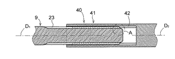
車両用パワートレインは、図5に示すように、軸方向の変位を吸収するためのスプライン摺動部40を備える。
As shown in FIG. 5, the vehicle power train includes a
例えばスプライン摺動部40は、トランスミッションのアウトプットシャフト9の前端部外周に形成された雄側スプライン23と、アウトプットシャフト9の外周を覆うスリーブヨーク41の内周に形成され雄側スプライン23とスプライン嵌合される雌側スプライン42とを備える。雄側スプライン23及び雌側スプライン42は、それぞれ軸方向に延びて形成され、互いに軸方向に摺動自在に構成される。
For example, the
ところで、スプライン摺動部40は、アイドル状態のAT車両をフットブレーキを踏むなどして停止させているときなど、エンジンから流体クラッチを介して比較的大きなトルクを受けている状態では摺動せず、ブレーキリリース時など、雄側スプライン23及び雌側スプライン42に作用するトルクが小さくなったとき摺動しやすい。
By the way, the
また、ブレーキリリース時にスプライン摺動部40が軸方向に急激に摺動した場合、駆動系全体が軸方向に急激に変位することとなり、駆動系から異音や振動が発生しやすい。例えば、図5のA部を拡大した図6に示すように、アウトプットシャフト9の軸方向D1に対してスリーブヨーク41の軸方向D2が若干傾き、雄側スプライン23の前端E(図6参照)が雌側スプライン42の歯面42aに局所的に当たった状態から摺動し始めた場合、スプライン摺動部40が軸方向に急激に摺動しやすく、駆動系から異音や振動が発生しやすい。
Further, when the
このため、雌側スプライン42には、摩擦低減のためのコーティングやメッキ等の表面処理が所定の条件のもとで施される。この所定の条件とは耐久性である。例えば、コーティング等が剥がれ、これが異物となってトランスミッション等の内部に侵入した場合、トランスミッション等に機能低下が生じるおそれがある。このため、一定の耐久性を満足する表面処理であることが条件となる。
Therefore, the
しかし、かかる耐久性を満足する表面処理には、十分な摩擦低減効果を有し且つ安価なものが存在しない。このため、耐久性を満足する表面処理のみでは、十分な異音対策および振動対策は困難である。また、特殊な表面処理及び構造はコスト上昇の要因となる。 However, there is no inexpensive surface treatment that has a sufficient friction reducing effect and satisfies such durability. Therefore, it is difficult to take sufficient measures against abnormal noise and vibration only by surface treatment that satisfies the durability. In addition, special surface treatments and structures are factors that increase costs.
そこで本開示は、かかる事情に鑑みて創案され、その目的は、駆動系からの異音や振動を安価に抑制できる車両用パワートレインのスプライン摺動部構造を提供することにある。 Therefore, the present disclosure was conceived in view of such circumstances, and an object thereof is to provide a spline sliding portion structure of a power train for a vehicle capable of suppressing abnormal noise and vibration from a drive system at low cost.
本開示の一の態様によれば、
前方に延びるアウトプットシャフトの前端部外周に、前後方向に延びて形成された雄側スプラインと、
前記雄側スプラインの外周を囲む筒状に形成されたスリーブ部と、
前記スリーブ部の内周に形成され前記雄側スプラインとスプライン嵌合される雌側スプラインと、
前記スリーブ部内に形成され、前記雄側スプラインの前端部を前記雌側スプラインの前方に延出させた状態で収容するオーバーハング収容部と、
を備えたことを特徴とする車両用パワートレインのスプライン摺動部構造が提供される。
According to one aspect of the present disclosure
A male spline formed extending in the front-rear direction on the outer circumference of the front end of the output shaft extending forward,
A tubular sleeve portion that surrounds the outer circumference of the male spline,
A female spline formed on the inner circumference of the sleeve portion and fitted with the male spline,
An overhang accommodating portion formed in the sleeve portion and accommodating the front end portion of the male spline in a state of extending in front of the female spline.
Provided is a spline sliding portion structure of a power train for a vehicle, which comprises the above.
好ましくは、前記オーバーハング収容部は、断面円形の空間で構成されると共に、前記雄側スプラインの外径よりも大径に形成される。 Preferably, the overhang accommodating portion is formed of a space having a circular cross section and is formed to have a diameter larger than the outer diameter of the male spline.
好ましくは、前記スリーブ部と前記アウトプットシャフトには、前後方向の摺動範囲が予め設定され、前記オーバーハング収容部は、前記スリーブ部が前記摺動範囲において最も前方に摺動されたときであっても、前記雄側スプラインの前端部を前記雌側スプラインの前方に延出させた状態で収容するように形成される。 Preferably, the sleeve portion and the output shaft are preset with a sliding range in the front-rear direction, and the overhang accommodating portion is when the sleeve portion is slid most forward in the sliding range. However, it is formed so as to accommodate the front end portion of the male spline in a state of extending in front of the female spline.
好ましくは、前記アウトプットシャフトがトランスミッションのアウトプットシャフトで構成され、前記スリーブ部がプロペラシャフトを構成する。 Preferably, the output shaft is composed of an output shaft of a transmission, and the sleeve portion constitutes a propeller shaft.
好ましくは、前記雌側スプラインには、ナイロンコートが施される。 Preferably, the female spline is coated with nylon.
上記の態様によれば、駆動系からの異音や振動を安価に抑制できる。 According to the above aspect, abnormal noise and vibration from the drive system can be suppressed at low cost.
以下、添付図面を参照して本開示の実施形態を説明する。なお、後述する実施の形態においては、説明の便宜のため、トランスミッション3のアウトプットシャフト9の延長方向を前方(車両における前後方向とは逆)とする。
Hereinafter, embodiments of the present disclosure will be described with reference to the accompanying drawings. In the embodiment described later, for convenience of explanation, the extension direction of the
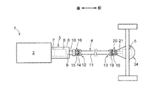
図1は、本実施形態に係る車両用パワートレイン1を車両における上方から視た概略上面図である。車両用パワートレイン1は、エンジン(内燃機関)2と、エンジン2に接続されるトランスミッション3と、トランスミッション3に接続されるプロペラシャフト4と、プロペラシャフト4に接続されるファイナルギア5とを備える。
FIG. 1 is a schematic top view of the vehicle power train 1 according to the present embodiment as viewed from above in the vehicle. The vehicle power train 1 includes an engine (internal combustion engine) 2, a transmission 3 connected to the
トランスミッション3は、ハウジング6と、ハウジング6内に収容されエンジン2と接続される流体クラッチ7と、ハウジング6内に収容され流体クラッチ7と接続される変速機構8とを備える。変速機構8はプロペラシャフト4に回転駆動力を伝達するためのアウトプットシャフト9を備える。アウトプットシャフト9は、前方に延びて形成される。また、ハウジング6には、アウトプットシャフト9の外周を径方向に間隔を隔てて覆う筒状のカバー部10が形成されている。
The transmission 3 includes a
プロペラシャフト4は、前後方向に延びるロッド部11と、ロッド部11の後端(トランスミッション3側の端)に設けられアウトプットシャフト9に接続される第1カルダンジョイント12と、ロッド部11の前端に設けられファイナルギア5に接続される第2カルダンジョイント13とを備える。
The
図1及び図2に示すように、第1カルダンジョイント12は、ロッド部11の後端に設けられたU字状の第1結合腕部14と、第1結合腕部14にクロススパイダ15を介して屈曲自在に連結されるスリーブヨーク16とを備える。スリーブヨーク16は、筒状に形成されたスリーブ部17と、スリーブ部17の前端に設けられクロススパイダ15を介して第1結合腕部14に屈曲自在に結合される第2結合腕部18とを備える。スリーブ部17は、アウトプットシャフト9に対して前後方向に摺動自在にスプライン嵌合される。また、スリーブ部17とアウトプットシャフト9には、前後方向の摺動範囲が予め設定されている。この摺動範囲について簡単に説明する。
As shown in FIGS. 1 and 2, the
例えば、平地で駐車状態のとき、アウトプットシャフト9に対してスリーブ部17が最も後方(トランスミッション3側)に位置されるように設定された車両を想定する。かかる車両が悪路等を走行した場合、ファイナルギア5を収容するアクスルケース34(図1参照)が路面の凹凸に応じて昇降する。このとき、アクスルケース34は、車高方向に直線的に昇降する。このため、アクスルケース34が駐車状態の位置から上昇又は降下の限界位置まで移動した場合、アウトプットシャフト9からファイナルギア5までの直線距離も限界まで長くなる。この限界まで長くなった直線距離と、平地で駐車状態におけるアウトプットシャフト9からファイナルギア5までの直線距離との差が、概ねスプライン摺動部22に求められる摺動範囲となる。
For example, assume a vehicle in which the
すなわち、スリーブ部17とアウトプットシャフト9は、前記摺動範囲内で摺動するように予め設定されている。
That is, the
第2カルダンジョイント13は、ロッド部11の前端に設けられた第3結合腕部19と、第3結合腕部19にクロススパイダ15を介して屈曲自在に結合されるフランジヨーク20とを備える。フランジヨーク20は、ファイナルギア5の入力軸21にフランジ結合される。
The
さて、本実施の形態にかかる車両用パワートレイン1は、軸方向の変位を吸収するためのスプライン摺動部22を備える。このスプライン摺動部22について説明する。
The vehicle power train 1 according to the present embodiment includes a
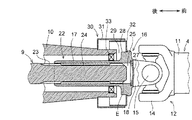
図2及び図3に示すように、スプライン摺動部22は、アウトプットシャフト9の前端部外周に形成される雄側スプライン23と、スリーブ部17と、スリーブ部17の内周に形成され雄側スプライン23とスプライン嵌合される雌側スプライン24と、スリーブ部17内に形成され雄側スプライン23の前端部23aを雌側スプライン24の前方に延出させた状態で収容するオーバーハング収容部25とを備える。
As shown in FIGS. 2 and 3, the
雄側スプライン23は、前方に延びるアウトプットシャフト9の前端部外周に、前後方向に延びて形成される。また、雄側スプライン23は、アウトプットシャフト9の周方向に沿って複数形成されている。また、アウトプットシャフト9の前端には、その外周に沿って面取26が施されている。これにより、雄側スプライン23の前端Eは、径方向外方に向かうにつれて後方に退くように傾斜される。
The
スリーブ部17は、筒状に形成される。スリーブ部17は、雄側スプライン23の外周を囲むと共にハウジング6のカバー部10内に挿入される。また、スリーブ部17には、その前端開口を液密に塞ぐプラグ27が設けられる。具体的には、スリーブ部17の前端部には、プラグ27を嵌合させるための嵌合部35が形成される。プラグ27は、円盤状に形成されると共に、中央部を前方に膨らませるように湾曲して形成される。プラグ27は、嵌合部35内に嵌合されることでスリーブ部17の前端開口を液密に塞ぐ。プラグ27は、プレス鋼板で構成される。なお、プラグ27の材料はこれに限られない。例えばプラグ27は他の金属で構成されてもよく、樹脂で構成されてもよい。
The
また、スリーブ部17の前端部には、鍔部28が設けられる。鍔部28は、その後方のスリーブ部17より外径を大きく形成されている。鍔部28には、第2結合腕部18が設けられている。
Further, a
また、鍔部28及びカバー部10には、鍔部28とカバー部10の間に形成される隙間29を覆うためのダストカバー30が設けられる。ダストカバー30は、カバー部10に設けられる親カバー31と、鍔部28に設けられ親カバー31内に遊嵌される子カバー32とを備える。また、鍔部28より後方のスリーブ部17の外周面とカバー部10の内周面との間には、オイルシール33が設けられている。
Further, the
図3に示すように、オーバーハング収容部25は、スリーブ部17内の前部に形成される。また、オーバーハング収容部25は、断面円形の空間で構成されると共に、雄側スプライン23の外径よりも大径に形成される。すなわち、スリーブ部17内の空間のうち、雌側スプライン24より前方の雌側スプライン24が形成されない領域Rがオーバーハング収容部25となる。オーバーハング収容部25は、雄側スプライン23の前端部23aを雌側スプライン24の前方に延出させた状態で収容することで、雄側スプライン23の前端Eが雌側スプライン24に接触するのを防ぐ。
As shown in FIG. 3, the
また、スリーブ部17とアウトプットシャフト9に予め設定された摺動範囲において、スリーブ部17は、アウトプットシャフト9に対して最も前方に摺動されたときであっても、雄側スプライン23の前端部23aを雌側スプライン24の前方に延出させた状態にするように形成される。すなわち、オーバーハング収容部25の前後方向の長さは、前記摺動範囲の長さ以上に設定される。
Further, in the sliding range preset for the
また、雌側スプライン24の前端24aは、径方向内方に向かうにつれて後方に退くように傾斜して形成される。
Further, the
また、雌側スプライン24の後端は、径方向内方に向かうにつれて前方に退くように傾斜して形成される。これにより、スリーブ部17内にアウトプットシャフト9を挿入して雌側スプライン24と雄側スプライン23を嵌合させ始めるとき、雌側スプライン24の前端24aと雄側スプライン23の前端Eとが当たって傷つけ合うことを抑制できる。
Further, the rear end of the
次に本実施の形態の作用について述べる。 Next, the operation of this embodiment will be described.
走行中の車両が比較的急なブレーキで停車した場合、アウトプットシャフト9には、エンジン2から流体クラッチ7を介して回転駆動力が伝わっている。これにより、雄側スプライン23と雌側スプライン24にはトルクが掛かり、雄側スプライン23の歯面23bは雌側スプライン24の歯面24bに圧着された状態となる。そして、雄側スプライン23と雌側スプライン24は、互いに摺動し難い状態となる。またこのとき、スリーブ部17は、停車時のサスペンションの伸縮の影響で、図4に示すように、アウトプットシャフト9に対して前方に移動されると共に、若干傾斜された状態になる。
When the running vehicle is stopped by a relatively sudden brake, the rotational driving force is transmitted from the
この後、ブレーキが解除されると、雄側スプライン23と雌側スプライン24に掛かっていたトルクは抜け、雄側スプライン23と雌側スプライン24は、摺動しやすい状態になる。これにより、図2に示すように、スリーブ部17に形成された雌側スプライン24は、雄側スプライン23に対して後方に摺動する。また、アウトプットシャフト9に対してスリーブ部17が停車中に若干傾斜されているので、雄側スプライン23に対して雌側スプライン24は若干片当たりの状態から摺動し始める。
After that, when the brake is released, the torque applied to the
図6に示すように、このような場合、従来のスプライン摺動部40にあっては、雄側スプライン23の前端Eが雌側スプライン42の歯面42aに局所的に当たり、スプライン摺動部40が摺動し難い状態から摺動し始めることとなる。このため、スプライン摺動部40が、ブレーキの解除から一瞬遅れて軸方向に急激に摺動することがあった。この場合、駆動系から異音や振動が発生しやすい。また、雌側スプライン42にコーティングやメッキ等の表面処理が施されている場合、その表面処理層が剥がれて異物となり、その異物がトランスミッション3内に侵入するおそれがあった。
As shown in FIG. 6, in such a case, in the conventional
しかし、図3に示すように、本実施の形態に係るスプライン摺動部22は、雄側スプライン23の前端部23aを雌側スプライン24の前方に延出させた状態で収容するオーバーハング収容部25を備える。このため、雄側スプライン23の前端Eが雌側スプライン24の歯面24bに当たることはなく、スプライン摺動部22はブレーキが解除されると同時にスムーズに摺動し始める。このため、駆動系から異音や振動が発生することを抑制できる。
However, as shown in FIG. 3, the
また、オーバーハング収容部25は、スリーブ部17がアウトプットシャフト9に対して最も前方に摺動されたときであっても、雄側スプライン23の前端部23aを雌側スプライン24の前方に延出させた状態で収容するように形成されている。このため、スリーブ部17とアウトプットシャフト9が予め設定された摺動範囲内で摺動している限り、雄側スプライン23の前端Eが雌側スプライン24の歯面24bに当たることはなく、スプライン摺動部22の急激な摺動を抑制できる。
Further, the
以上、本開示の実施形態を詳細に述べたが、本開示は以下のような他の実施形態も可能である。 Although the embodiments of the present disclosure have been described in detail above, the present disclosure may also include the following other embodiments.
(1)雌側スプライン24には、ナイロンコートが施されてもよい。ナイロンコートは、摩擦低減効果に優れ、比較的安価にできる。しかし、従来のスプライン摺動部40においては、雄側スプライン23の前端Eが雌側スプライン42の歯面42bに当たって攻撃する。このため、スプライン摺動部40からナイロン摩耗粉が発生することがあった。しかし、本実施の形態に係るスプライン摺動部22においては、雄側スプライン23の前端Eが雌側スプライン24の表面処理層(図示せず)に当たることはない。このため、表面処理層に求められる耐久性能を下げることができ、ナイロンコートを採用することができる。そして、雌側スプライン24にナイロンコートを施した場合、雄側スプライン23と雌側スプライン24の摺動抵抗を低減でき、異音や振動の発生をさらに抑制できる。
(1) The
(2)スリーブ部17は、プロペラシャフト4のスリーブヨーク16の一部であるものについて説明したがこれに限られない。例えば、プロペラシャフト4が第1カルダンジョイント12を備えない場合、スリーブ部17は、プロペラシャフト4のロッド部11に一体に設けられるものであってもよい。また、プロペラシャフト4が第1カルダンジョイント12の位置に等速ジョイント(図示せず)を備える場合、スリーブ部17は、等速ジョイントのアウターレース又はインナーレースに一体に設けられるものであってもよい。また、スリーブ部17は、ドライブシャフト(FF駆動車における駆動軸:図示せず)の一部であってもよい。
(2) The
(3)アウトプットシャフト9がトランスミッション3のアウトプットシャフト9で構成される場合について説明したが、これに限られない。アウトプットシャフト9は、トランスファー(トランスミッション3からの回転駆動力を分配する装置:図示せず)のものであってもよい。
(3) The case where the
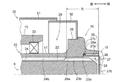
(4)プラグ27は、円盤状に形成されると共に、中央部を前方に膨らませるように湾曲して形成されるものとしたが、これに限られない。図7に示すように、プラグ27は、嵌合部35に嵌合される筒部27aと、筒部27aの前端を塞ぐ蓋部27bとを備えるものであってもよい。この場合、オーバーハング収容部25を、蓋部27bより後方のプラグ27内にも形成でき、前方に延長できる。すなわち、雌側スプライン24より前方かつ蓋部27bより後方の領域Rにオーバーハング収容部25を形成できる。これにより、プロペラシャフト4の全長に係る制約(プロペラシャフト全長制約)をクリアしつつ、雄側スプライン23及び雌側スプライン24に求められる噛み合い長さ(スプライン必要噛合い長さ)の確保を容易にできる。
(4) The
また、図7に示すプラグ27は、スリーブ部17に筒部27aを全周に亘ってカシメられて固定されるものとしたが、これに限られない。例えば、プラグ27は、スリーブ部17に部分カシメにて固定されるものであってもよい。また、図8に示すように、プラグ27は、スリーブ部17に嵌め込みにて固定されてもよい。この場合、嵌合部35には、内周側に突起する内爪35aが形成され、筒部27aには、内爪35aの後端に係止される外爪27cが外周側に突起して形成されるとよい。
Further, in the
前述の各実施形態の構成は、特に矛盾が無い限り、部分的にまたは全体的に組み合わせることが可能である。本開示の実施形態は前述の実施形態のみに限らず、特許請求の範囲によって規定される本開示の思想に包含されるあらゆる変形例や応用例、均等物が本開示に含まれる。従って本開示は、限定的に解釈されるべきではなく、本開示の思想の範囲内に帰属する他の任意の技術にも適用することが可能である。 The configurations of each of the above embodiments can be combined partially or wholly, unless otherwise inconsistent. The embodiments of the present disclosure are not limited to the above-described embodiments, and all modifications, applications, and equivalents included in the ideas of the present disclosure defined by the scope of claims are included in the present disclosure. Therefore, the present disclosure should not be construed in a limited manner and may be applied to any other technique belonging within the scope of the ideas of the present disclosure.
1 車両用パワートレイン
2 エンジン
3 トランスミッション
4 プロペラシャフト
5 ファイナルギア
6 ハウジング
7 流体クラッチ
8 変速機構
9 アウトプットシャフト
10 カバー部
11 ロッド部
12 第1カルダンジョイント
13 第2カルダンジョイント
14 第1結合腕部
15 クロススパイダ
16 スリーブヨーク
17 スリーブ部
18 第2結合腕部
19 第3結合腕部
20 フランジヨーク
21 入力軸
22 スプライン摺動部
23 雄側スプライン
23a 前端部
23b 歯面
24 雌側スプライン
24a 前端
24b 歯面
25 オーバーハング収容部
26 面取
27 プラグ
28 鍔部
29 隙間
30 ダストカバー
31 親カバー
32 子カバー
33 オイルシール
34 アクスルケース
40 スプライン摺動部
41 スリーブヨーク
42 雌側スプライン
42a 歯面
E 前端
R 領域
1
Claims (5)
前記雄側スプラインの外周を囲む筒状に形成されたスリーブ部と、
前記スリーブ部の内周に形成され前記雄側スプラインとスプライン嵌合される雌側スプラインと、
前記スリーブ部内に形成され、前記雄側スプラインの前端部を前記雌側スプラインの前方に延出させた状態で収容するオーバーハング収容部と、
を備えたことを特徴とする車両用パワートレインのスプライン摺動部構造。 A male spline formed extending in the front-rear direction on the outer circumference of the front end of the output shaft extending forward,
A tubular sleeve portion that surrounds the outer circumference of the male spline,
A female spline formed on the inner circumference of the sleeve portion and fitted with the male spline,
An overhang accommodating portion formed in the sleeve portion and accommodating the front end portion of the male spline in a state of extending in front of the female spline.
The spline sliding part structure of the power train for vehicles, which is characterized by being equipped with.
請求項1に記載の車両用パワートレインのスプライン摺動部構造。 The spline sliding portion structure for a vehicle power train according to claim 1, wherein the overhang accommodating portion is formed of a space having a circular cross section and is formed to have a diameter larger than the outer diameter of the male spline.
前記オーバーハング収容部は、前記スリーブ部が前記摺動範囲において最も前方に摺動されたときであっても、前記雄側スプラインの前端部を前記雌側スプラインの前方に延出させた状態で収容するように形成された
請求項1又は2に記載の車両用パワートレインのスプライン摺動部構造。 A sliding range in the front-rear direction is preset in the sleeve portion and the output shaft.
The overhang accommodating portion is in a state in which the front end portion of the male spline extends forward of the female spline even when the sleeve portion is slid most forward in the sliding range. The spline sliding portion structure of the vehicle power train according to claim 1 or 2, which is formed to accommodate the spline.
前記スリーブ部がプロペラシャフトを構成する
請求項1から3のいずれか一項に記載の車両用パワートレインのスプライン摺動部構造。 The output shaft is composed of the output shaft of the transmission.
The spline sliding portion structure of a vehicle power train according to any one of claims 1 to 3, wherein the sleeve portion constitutes a propeller shaft.
請求項1から4のいずれか一項に記載の車両用パワートレインのスプライン摺動部構造。 The spline sliding portion structure of a vehicle power train according to any one of claims 1 to 4, wherein the female side spline is coated with nylon.
Priority Applications (2)
| Application Number | Priority Date | Filing Date | Title |
|---|---|---|---|
| JP2019028259A JP2020133763A (en) | 2019-02-20 | 2019-02-20 | Spline slide part structure of vehicle powertrain |
| PCT/JP2020/001317 WO2020170660A1 (en) | 2019-02-20 | 2020-01-16 | Spline sliding part structure for vehicular powertrain |
Applications Claiming Priority (1)
| Application Number | Priority Date | Filing Date | Title |
|---|---|---|---|
| JP2019028259A JP2020133763A (en) | 2019-02-20 | 2019-02-20 | Spline slide part structure of vehicle powertrain |
Publications (1)
| Publication Number | Publication Date |
|---|---|
| JP2020133763A true JP2020133763A (en) | 2020-08-31 |
Family
ID=72144434
Family Applications (1)
| Application Number | Title | Priority Date | Filing Date |
|---|---|---|---|
| JP2019028259A Pending JP2020133763A (en) | 2019-02-20 | 2019-02-20 | Spline slide part structure of vehicle powertrain |
Country Status (2)
| Country | Link |
|---|---|
| JP (1) | JP2020133763A (en) |
| WO (1) | WO2020170660A1 (en) |
Citations (7)
| Publication number | Priority date | Publication date | Assignee | Title |
|---|---|---|---|---|
| JPS6012724U (en) * | 1983-07-06 | 1985-01-28 | ティー・シー・エム株式会社 | Propulsion transmission device for work vehicles |
| JPS6149133U (en) * | 1984-09-04 | 1986-04-02 | ||
| JPH07248026A (en) * | 1994-03-11 | 1995-09-26 | Nissan Diesel Motor Co Ltd | Propeller shaft |
| JPH10231846A (en) * | 1997-02-24 | 1998-09-02 | Taiyo Tanko Kk | Power takeoff shaft in tractor |
| WO1998048186A1 (en) * | 1997-04-21 | 1998-10-29 | Rockford Powertrain, Inc. | Inverted slip driveline |
| US20170067503A1 (en) * | 2015-09-08 | 2017-03-09 | Hyundai Motor Company | Propeller shaft with locking device |
| JP2017211041A (en) * | 2016-05-26 | 2017-11-30 | アイシン精機株式会社 | Press-fit structure |
-
2019
- 2019-02-20 JP JP2019028259A patent/JP2020133763A/en active Pending
-
2020
- 2020-01-16 WO PCT/JP2020/001317 patent/WO2020170660A1/en not_active Ceased
Patent Citations (7)
| Publication number | Priority date | Publication date | Assignee | Title |
|---|---|---|---|---|
| JPS6012724U (en) * | 1983-07-06 | 1985-01-28 | ティー・シー・エム株式会社 | Propulsion transmission device for work vehicles |
| JPS6149133U (en) * | 1984-09-04 | 1986-04-02 | ||
| JPH07248026A (en) * | 1994-03-11 | 1995-09-26 | Nissan Diesel Motor Co Ltd | Propeller shaft |
| JPH10231846A (en) * | 1997-02-24 | 1998-09-02 | Taiyo Tanko Kk | Power takeoff shaft in tractor |
| WO1998048186A1 (en) * | 1997-04-21 | 1998-10-29 | Rockford Powertrain, Inc. | Inverted slip driveline |
| US20170067503A1 (en) * | 2015-09-08 | 2017-03-09 | Hyundai Motor Company | Propeller shaft with locking device |
| JP2017211041A (en) * | 2016-05-26 | 2017-11-30 | アイシン精機株式会社 | Press-fit structure |
Also Published As
| Publication number | Publication date |
|---|---|
| WO2020170660A1 (en) | 2020-08-27 |
Similar Documents
| Publication | Publication Date | Title |
|---|---|---|
| JP6208327B2 (en) | Propeller shaft and constant velocity joint used for this propeller shaft | |
| JP2008273268A (en) | Propeller shaft for automobile | |
| US20200340570A1 (en) | Transmission system | |
| EP3571421B1 (en) | Retainer for rotating members | |
| CN101797870B (en) | Coupling of a constant velocity joint and a hub bearing unit of a motor vehicle wheel | |
| WO2019054167A1 (en) | Power transmission shaft | |
| WO2016004891A1 (en) | Vehicle and anti-rollback system therefor | |
| JP2019515201A (en) | Constant velocity joint boot assembly | |
| US7115059B2 (en) | Pinion housing with contaminant deflector | |
| KR101360381B1 (en) | Uncoupling drive | |
| CN105358852B (en) | Bearing apparatus for wheel | |
| US20130074648A1 (en) | Fastening structure for ring-gear and differential case, and differential device using same | |
| KR20140069451A (en) | Coupling structure of propeller shaft in vehicle | |
| JP2020133763A (en) | Spline slide part structure of vehicle powertrain | |
| JP7214499B2 (en) | Sliding spline structure for vehicle powertrain | |
| JP6128030B2 (en) | Automatic transmission | |
| US11326678B2 (en) | Friction disc apparatus and related torque converter assemblies for use with vehicles | |
| JP7379497B2 (en) | Propeller shaft and its manufacturing method | |
| KR20150049727A (en) | Axle device for vehlcle | |
| JPH09123774A (en) | Propeller shaft structure of automobile | |
| JP2008207575A (en) | Vehicle propulsion shaft | |
| US8142294B2 (en) | Power transmission shaft and propeller shaft for vehicle | |
| JP7732926B2 (en) | Drive system | |
| KR102918761B1 (en) | Rear differential module for 4 wheel driving vehicle | |
| JP6962809B2 (en) | Vehicle propulsion shaft |
Legal Events
| Date | Code | Title | Description |
|---|---|---|---|
| A521 | Request for written amendment filed |
Free format text: JAPANESE INTERMEDIATE CODE: A821 Effective date: 20190220 |
|
| A521 | Request for written amendment filed |
Free format text: JAPANESE INTERMEDIATE CODE: A821 Effective date: 20190826 |
|
| A711 | Notification of change in applicant |
Free format text: JAPANESE INTERMEDIATE CODE: A712 Effective date: 20190826 |
|
| A521 | Request for written amendment filed |
Free format text: JAPANESE INTERMEDIATE CODE: A821 Effective date: 20210903 |
|
| A621 | Written request for application examination |
Free format text: JAPANESE INTERMEDIATE CODE: A621 Effective date: 20210903 |
|
| A131 | Notification of reasons for refusal |
Free format text: JAPANESE INTERMEDIATE CODE: A131 Effective date: 20221122 |
|
| A521 | Request for written amendment filed |
Free format text: JAPANESE INTERMEDIATE CODE: A821 Effective date: 20230119 Free format text: JAPANESE INTERMEDIATE CODE: A523 Effective date: 20230119 |
|
| A131 | Notification of reasons for refusal |
Free format text: JAPANESE INTERMEDIATE CODE: A131 Effective date: 20230418 |
|
| A02 | Decision of refusal |
Free format text: JAPANESE INTERMEDIATE CODE: A02 Effective date: 20231010 |