JP2020148043A - Material transportation system and lift equipment - Google Patents
Material transportation system and lift equipment Download PDFInfo
- Publication number
- JP2020148043A JP2020148043A JP2019047522A JP2019047522A JP2020148043A JP 2020148043 A JP2020148043 A JP 2020148043A JP 2019047522 A JP2019047522 A JP 2019047522A JP 2019047522 A JP2019047522 A JP 2019047522A JP 2020148043 A JP2020148043 A JP 2020148043A
- Authority
- JP
- Japan
- Prior art keywords
- segment
- lift device
- tunnel
- transport device
- transportation system
- Prior art date
- Legal status (The legal status is an assumption and is not a legal conclusion. Google has not performed a legal analysis and makes no representation as to the accuracy of the status listed.)
- Granted
Links
Images

Landscapes
- Lining And Supports For Tunnels (AREA)
Abstract
【課題】段差を有するトンネル坑内において、資材等の輸送を効率的に行うことを可能とした資材輸送システムおよびリフト装置を提案する。【解決手段】坑口部から切羽近傍まで資材を輸送する搬送装置3と、トンネル軸方向に移動可能な走行式リフト装置5とを備える資材輸送システム1であって、搬送装置3は、トンネル坑内を自走する牽引車31と、牽引車31に連結されたセグメント台車32とを備えており、走行式リフト装置5は、搬送装置3全体を上下動させることを可能としている。【選択図】図1A material transportation system and a lift device are proposed that enable efficient transportation of materials and the like in a tunnel pit having steps. A materials transportation system 1 includes a transportation device 3 that transports materials from a wellhead to the vicinity of a face, and a traveling lift device 5 that can move in a tunnel axial direction, and the transportation device 3 moves through the inside of the tunnel. It is equipped with a self-propelled tractor 31 and a segment carriage 32 connected to the tractor 31, and the traveling lift device 5 enables the entire conveying device 3 to move up and down. [Selection drawing] Fig. 1
Description
本発明は、資材輸送システムおよびリフト装置に関する。 The present invention relates to material transportation systems and lift devices.
シールドトンネルでは、セグメントピースを組み合わせることにより形成されたセグメントリングをシールドマシンの後方に配置することで、覆工を形成する。セグメントピースは、トンネル坑外で製作されたものを切羽まで搬送する。シールドトンネルの施工では、シールドマシンによる施工の進捗に応じて、セグメントピースを含む資材を坑口側から切羽へと搬送するとともに、地山の掘削により発生した土砂(ズリ)を搬出する必要がある。一方、トンネル坑内には、多種多様な設備や装置が配設されているため、輸送手段の走行路が限定されている。
そのため、複数の搬送台車が行きかうトンネル坑内では、例えば、所定の位置に待避所を設けることにより、搬送台車同士がすれ違うことを可能にしている。また、特許文献1では、坑口から切羽近傍までの間において、搬送台車により搬送した資材等を、分岐路上に待機させた坑内台車に移し替えて待機させた後、所望のタイミングで坑内台車を介して切羽に供給する施工方法が開示されている。
ところで、坑口から切羽までの資材等の輸送を1編成で行うことができれば、複数の台車を待避させる場合や、台車同士の間で資材を移し替える場合に比べて、効率的に作業を行うことができる。そのため、特許文献2では、資材の搬入と掘削ズリの搬出を効率的に行うことを目的として、牽引車を挟んで切羽側にセグメント台車を着脱可能に連結するとともに、坑口側にズリ搬出台車を連結した編成の搬送装置を利用している。
In a shield tunnel, a lining is formed by arranging a segment ring formed by combining segment pieces behind the shield machine. The segment piece transports the one manufactured outside the tunnel to the face. In the construction of a shield tunnel, it is necessary to transport the material including the segment piece from the wellhead side to the face according to the progress of the construction by the shield machine, and to carry out the earth and sand (slip) generated by the excavation of the ground. On the other hand, since a wide variety of equipment and devices are arranged in the tunnel mine, the travel path of the transportation means is limited.
Therefore, in the tunnel mine where a plurality of transport carriages come and go, for example, by providing a shelter at a predetermined position, the transport carriages can pass each other. Further, in Patent Document 1, materials and the like transported by the transport carriage are transferred from the wellhead to the vicinity of the face to the underground carriage that has been made to stand by on the branch road and waited, and then the materials and the like are made to stand by via the underground carriage at a desired timing. The construction method to supply to the face is disclosed.
By the way, if it is possible to transport materials, etc. from the wellhead to the face in one train, the work will be more efficient than when multiple trolleys are evacuated or when materials are transferred between trolleys. Can be done. Therefore, in
長距離の大断面トンネルでは、シールドマシンによる切羽でのトンネルの掘進に伴い、シールドマシンの後方において床版の施工を同時に行う場合がある。このようなトンネルでは、床版が形成された坑口側と、床版が形成される前の切羽側との間において、段差があり、切羽近傍から坑口部までの区間における資材の輸送を同一の搬送装置により行うのが困難となる。
本発明は、前記の問題点を解決することを目的とするものであり、段差を有するトンネル坑内において、資材等の輸送を効率的に行うことを可能とした資材輸送システムおよびリフト装置を提案することを課題とする。
In a long-distance large-section tunnel, the floor slab may be constructed at the same time behind the shield machine as the tunnel is dug with the face by the shield machine. In such a tunnel, there is a step between the wellhead side where the slab is formed and the face side before the slab is formed, and the transportation of materials in the section from the vicinity of the face to the wellhead is the same. It becomes difficult to carry out by the transport device.
An object of the present invention is to solve the above-mentioned problems, and to propose a material transportation system and a lift device capable of efficiently transporting materials and the like in a tunnel having a step. That is the issue.
前記課題を解決するための本発明の資材輸送システムは、坑口部から切羽近傍まで資材を輸送する搬送装置と、トンネル軸方向に移動可能なリフト装置とを備えている。前記搬送装置は、トンネル坑内を自走する牽引車と、前記牽引車に連結された台車とを有している。また、前記リフト装置は、前記搬送装置全体を上下動させることを可能としている。
このような資材輸送システムに用いられるリフト装置は、支持枠と、前記支持枠内に設けられた昇降床と、前記昇降床を上下動させる昇降手段とを備えているのが望ましい。なお、前記昇降床は、牽引車と前記牽引車に連結された複数の台車とからなる搬送装置を上載可能な面積を有しており、前記昇降手段は、前記搬送装置が上載された前記昇降床を上下動させる能力を有している。
かかる資材輸送システムおよびリフト装置によれば、搬送装置を上下動させるため、段差を有しているトンネル内においても、坑口部から切羽近傍までの資材等の輸送を1編成の搬送装置により行うことができる。そのため、トンネル坑内において資材の移し替えなどの手間や時間を省略し、効率的に資材の搬入を行うことができる。なお、前記リフト装置の前記支持枠の脚部に車輪を備えていれば、トンネルの掘進に伴ってリフト装置を移動させる際の手間を低減することができる。
The material transportation system of the present invention for solving the above problems includes a transportation device for transporting materials from the wellhead to the vicinity of the face, and a lift device that can move in the tunnel axial direction. The transport device has a towing vehicle that runs in the tunnel mine and a carriage connected to the towing vehicle. In addition, the lift device makes it possible to move the entire transport device up and down.
It is desirable that the lift device used in such a material transportation system includes a support frame, an elevating floor provided in the support frame, and an elevating means for moving the elevating floor up and down. The elevating floor has an area on which a transport device including a traction vehicle and a plurality of carriages connected to the traction vehicle can be mounted, and the elevating means has the elevating means on which the transport device is mounted. It has the ability to move the floor up and down.
According to such a material transport system and a lift device, in order to move the transport device up and down, the transport of materials, etc. from the wellhead to the vicinity of the face is performed by one train of transport devices even in a tunnel having a step. Can be done. Therefore, it is possible to efficiently carry in the materials without saving the trouble and time of transferring the materials in the tunnel mine. If the legs of the support frame of the lift device are provided with wheels, it is possible to reduce the time and effort required to move the lift device as the tunnel is dug.
前記リフト装置と坑口との間に、前記搬送装置全体を上下動させることを可能とした定置式リフト装置をさらに備えていれば、トンネル坑内での作業状況に応じて、搬送装置を上下動させて、段差を有する搬送装置の走行路に対応することができる。
また、シールドマシンのエレクターに前記資材を順番に供給する資材供給装置と、前記台車から前記資材供給装置に前記資材を搬送する資材積替装置とをさらに備えていれば、セグメントピース等の資材を、効率的にシールドマシンに供給することができる。
If a stationary lift device that enables the entire transfer device to be moved up and down is further provided between the lift device and the wellhead, the transfer device can be moved up and down according to the work situation in the tunnel mine. Therefore, it is possible to correspond to the traveling path of the transport device having a step.
Further, if a material supply device for sequentially supplying the materials to the elector of the shield machine and a material transshipment device for transporting the materials from the carriage to the material supply device are further provided, materials such as segment pieces can be provided. , Can be efficiently supplied to the shield machine.
本発明の資材輸送システムおよびリフト装置によれば、搬送装置全体を上下動させることができるので、段差を有するトンネル坑内においても、1編成の搬送装置を利用して坑口部から切羽近傍まで資材等を効率的に輸送することが可能となる。 According to the material transportation system and the lift device of the present invention, the entire transport device can be moved up and down. Can be transported efficiently.
本実施形態では、大断面かつ長距離の道路トンネル(トンネルT)をシールド工法により構築する場合において、坑口からシールドマシン2までセグメントピース21を輸送するための資材輸送システム1について説明する。資材輸送システム1は、トンネル坑内に配設されており、トンネル坑外から搬入したセグメントピース21を切羽側へ輸送する。セグメントピース21は、例えば、トレーラーによりトンネル坑内へと搬入する。セグメントピース21のトンネル坑内への搬入手段はトレーラーに限定されるものではなく、例えば、クレーン等を利用してもよい。
In the present embodiment, a material transportation system 1 for transporting the
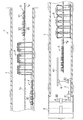
本実施形態の資材輸送システム1は、搬送装置3と、定置式リフト装置4と、走行式リフト装置5と、セグメント積替装置(資材積替装置)6と、セグメント供給装置(資材供給装置)7とを備えている。
トンネル坑内に搬入された複数のセグメントピース21は、搬送装置3を利用してシールドマシン2の近傍まで輸送する。トンネル坑内の一部では、床版TF上において作業を行っているため、搬送装置3は、坑口から所定の距離を床版TF上を走行した後、定置式リフト装置4により床版TFの下側に移動させる。そして、床版TFの下を所定の距離走行した後、走行式リフト装置5により上昇させて、再び床版TF上を走行してセグメント積替装置6までセグメントピース21を輸送する。その後、セグメントピース21は、セグメント供給装置7によりシールドマシン2に供給される。
The material transportation system 1 of the present embodiment includes a transport device 3, a stationary lift device 4, a traveling lift device 5, a segment transshipment device (material transshipment device) 6, and a segment supply device (material supply device). It is equipped with 7.
The plurality of
搬送装置3は、坑口部から切羽近傍までセグメントピース21を輸送する。本実施形態の搬送装置3は、トンネル坑内を自走する牽引車31と、牽引車31に連結されたセグメント台車32とを備えている。牽引車31には、1リング分のセグメントピース21を輸送できる台数のセグメント台車32が連結されている。なお、セグメント台車32の台数は限定されるものではない。また、搬送装置3は、セグメントピース21以外の資材や機器設備等を運ぶための台車や、作業員を乗せるための車両等が連結されていてもよい。搬送装置3は、トンネル坑内に敷設されたレール上を走行する。本実施形態では、坑口部から所定の距離においては、既設の床版TF上にレールが敷設されていて、その後の所定の延長においては床版TFの下にレールが敷設されており、その後、再び床版TF上にレールが敷設されている。レールの敷設個所が床版TFの上下に切り替えられる箇所においては、それぞれ定置式リフト装置4と走行式リフト装置5が配設されている。なお、床版TFの上下へのレールの切り替え個所および切替回数は限定されるものではなく、適宜決定すればよい。
The transport device 3 transports the
トレーラーにより搬入されたセグメントピース21は、坑口部(荷取り場所)において搬送装置3に積み替える。このとき、セグメントピース21は、セグメントリングを組み立てる際の順番により、切羽側のセグメント台車32から順に上載し、最後尾のセグメント台車32にKセグメントを上載する。セグメントピース21の積み替え作業では、まず、荷受装置(例えば、門型クレーン)によりトレーラー上のセグメントピース21を吊り上げる。次に、荷受装置によりセグメントピース21をセグメント台車32の上方に移動させた後、荷受装置によりセグメントピース21を下降させて、当該セグメントピース21をセグメント台車32に上載させる。なお、セグメントピース21の積み替え方法は限定されるものではなく、例えば、トレーラーから積み下ろしたセグメントピース21を所定の位置に仮置きしておき、所定のタイミングでセグメントピース21を搬送装置3に上載してもよい。また、荷受装置の構成は限定されるものではなく、例えば、フォークリフトやクレーン等であってもよい。
The
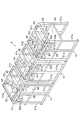
定置式リフト装置4は、搬送装置3全体を上下動させることを可能としている。図1に示すように、定置式リフト装置4は、走行式リフト装置5と坑口との間に配設されている。定置式リフト装置4は、図2に示すように、支持枠41と、支持枠41内に設けられた昇降床42と、昇降床42を上下動させる昇降手段43とを備えている。本実施形態の定置式リフト装置4は、3台の支持枠41を連結することにより形成されている。なお、支持枠41の台数は限定されるものではなく、搬送装置3の長さ等に応じて適宜決定すればよい。
The stationary lift device 4 makes it possible to move the entire transport device 3 up and down. As shown in FIG. 1, the stationary lift device 4 is arranged between the traveling lift device 5 and the wellhead. As shown in FIG. 2, the stationary lift device 4 includes a
支持枠41は、鋼材を組み合わせることにより形成されており、箱型状に形成されている。支持枠41のトンネル軸方向の前後は開口されていて、搬送装置3の出入りが可能となっている。3台の支持枠41が連結された定置式リフト装置4の全長は、搬送装置3の全長よりも大きい。また、支持枠41の前後の開口部は、搬送装置3の全幅よりも大きな幅を有しているとともに、搬送装置3の2倍以上の高さを有している。支持枠41は、トンネル横断方向に並ぶ左右一対の支柱41a,41aをトンネル軸方向に複数組備えている。左右に並設された支柱41a同士は、上端に横架された横材41bにより連結されている。また、トンネル軸方向前後に並設された支柱41aは、上端に延設された縦材41cにより連結されている。さらに、トンネル軸方向前後に並設された支柱41a同士を斜材により連結してもよい。
The
昇降床42は、搬送装置3(牽引車31および複数のセグメント台車32)を上載可能な面積を有している。昇降床42の上面には、レール(図示せず)が敷設されていて、搬送装置3の走行が可能に構成されている。昇降床42は、昇降手段43の動力により上下動する。昇降手段43は、駆動部44と、吊チェーン45とスプロケット46とを備えている。
駆動部44は、電動機44aと、減速機44bと、電磁ブレーキ44cとを備えている。電動機44aの動力が減速機44bを介して駆動軸44dに付与される。駆動軸44dには、吊チェーン45が周設されたスプロケット46が取り付けられている。吊チェーン45の一端は昇降床42に固定されていて、吊チェーン45の他端にはカウンターウェイト45aが取り付けられている。駆動部44を駆動させると、駆動軸44dを介してスプロケット46が回転して、吊チェーン45が上下動することで、昇降床42が上下動する。なお、昇降手段43の構成は限定されるものではない。例えば、ワイヤー式であってもよいし、ジャッキ式であってもよい。
The elevating
The
走行式リフト装置5は、トンネル軸方向に移動可能で、搬送装置3全体を上下動させることを可能としている。走行式リフト装置5は、図1に示すように、シールドマシン2の坑口側に配設されている。すなわち、走行式リフト装置5は、定置式リフト装置4とシールドマシン2との間に配設されている。走行式リフト装置5は、図3に示すように、支持枠51と、支持枠51内に設けられた昇降床52と、昇降床52を上下動させる昇降手段53とを備えている。本実施形態の走行式リフト装置5は、3台の支持枠51を連結することにより形成されている。なお、支持枠51の台数は限定されるものではなく、搬送装置3の長さ等に応じて適宜決定すればよい。
The traveling lift device 5 is movable in the direction of the tunnel axis, and the entire transport device 3 can be moved up and down. As shown in FIG. 1, the traveling lift device 5 is arranged on the wellhead side of the
支持枠51は、鋼材を組み合わせることにより形成されており、箱型状に形成されている。支持枠51のトンネル軸方向の前後は開口されていて、搬送装置3の出入りが可能となっている。3台の支持枠51が連結された走行式リフト装置5の全長は、搬送装置3の全長よりも大きい。また、支持枠51の前後の開口部は、搬送装置3の全幅よりも大きな幅を有しているとともに、搬送装置3の2倍以上の高さを有している。支持枠51は、トンネル横断方向に並ぶ左右一対の支柱51a,51aをトンネル軸方向に複数組備えている。左右に並設された支柱51a同士は、上端に横架された横材51bにより連結されている。また、トンネル軸方向前後に並設された支柱51aは、上端に延設された縦材51cにより連結されている。さらに、トンネル軸方向前後に並設された支柱51aは、斜材により連結してもよい。また、支持枠51の支柱51aの脚部には、車輪54が設けられている。車輪54は、走行式リフト5の下に敷設されたリフト用レール上を走行する。
The
昇降床52は、搬送装置3(牽引車31および複数のセグメント台車32)を上載可能な面積を有している。昇降床52の上面には、レールが敷設されていて、搬送装置3の走行が可能に構成されている。昇降床52は、昇降手段53の動力により上下動する。昇降手段53は、駆動部(例えば、ウィンチ)55とワイヤー56とプーリー57とを備えている。ワイヤー56は、駆動部55から延設されており、支持枠51に回転可能に設けられたプーリー57を介して上下に延設されているとともに、昇降床52に取り付けられている。駆動部55は、搬送装置3が上載された昇降床52を上下動させる能力を有している。すなわち、搬送装置3を上載させた状態で昇降手段53(駆動部55)を駆動させることで、昇降床52とともに搬送装置3が上下動する。なお、昇降手段53の構成は限定されるものではない。例えば、チェーン式であってもよいし、ジャッキ式であってもよい。
The elevating
セグメント積替装置6は、セグメント台車32からセグメント供給装置7にセグメントピース21を積み替えるものである。本実施形態のセグメント積替装置6は、図1に示すように、トンネル軸方向に沿って敷設されたレールと、レールを移動するクレーンとを備えている。セグメント積替装置6は、セグメント台車32上のセグメントピース21を、1個ずつ吊り上げて、切羽側に移動させた後、セグメント供給装置7上に載置する。
セグメント供給装置7は、シールドマシン2のエレクター22にセグメントピース21を順番に供給する。エレクター22は、セグメント供給装置7により供給されたセグメントピース21を所定の位置に移動させて、セグメントリングを組み立てる。
The segment transshipment device 6 transloads the
The
以上、本実施形態の資材輸送システム1によれば、定置式リフト装置4および走行式リフト装置5により搬送装置3を上下動させるため、資材の搬送路(搬送装置3の走行路)に段差を有している場合(例えば、坑口部の荷取り場所と走行路との段差や走行路と切羽側の荷渡し場所の段差等)であっても、坑口部からシールドマシン2の近傍までの資材等の輸送を1編成の搬送装置3により行うことができる。そのため、トンネル坑内において資材の移し替えなどの手間や時間を省略し、効率的に資材の搬入を行うことができる。
また、走行式リフト装置5は、脚部に車輪54を備えているため、トンネルTの掘進に伴って走行式リフト装置5を前進させる際の手間を低減することができる。なお、走行式リフト装置5をシールドマシン2に連結させておき、シールドマシン2とともに前進するようにしてもよい。
As described above, according to the material transportation system 1 of the present embodiment, in order to move the transport device 3 up and down by the stationary lift device 4 and the traveling lift device 5, a step is formed in the material transport path (travel path of the transport device 3). Materials from the wellhead to the vicinity of the
Further, since the traveling lift device 5 is provided with
以上、本発明に係る実施形態について説明したが、本発明は前述の実施形態に限られず、前記の各構成要素については本発明の趣旨を逸脱しない範囲で適宜変更が可能である。
例えば、前記実施形態では、定置式リフト装置4と、走行式リフト装置5との2台のリフト装置を使用する場合について説明したが、リフト装置の数および配置は限定されるものではない。例えば、床版TFの先端部(切羽側端部)に走行式リフト装置5を設置するのみとしてもよい。
前記実施形態では、走行式リフト装置5の坑口側に定置式リフト装置4を配設する場合について説明したが、走行式リフト装置5の坑口側に他の走行式リフト装置5を配設してもよい。
走行路の段差は、床版の有無により形成されるものに限定されるものではない。
また、前記実施形態では、セグメント台車32により輸送したセグメントピース21を、セグメント積替装置6を介してセグメント供給装置7に直接積み替える場合について説明したが、セグメント台車32とセグメント供給装置7との間に他の輸送手段を備えていてもよい。例えば、セグメント台車32からタイヤ式の自走式セグメント台車(図示せず)に積み替えてから、レールを敷設できない路盤上を自走式セグメント台車によりセグメントピース21をセグメント積替装置6まで輸送してもよい。
また、搬送装置3を直接シールドマシン2内まで進入させることで、セグメントピース21を積み替えることなく、エレクター22まで直接輸送してもよい。
また、前記実施形態では、1編成の搬送装置3を使用するものとしたが、複数編成の搬送装置3を使用してもよい。
Although the embodiments according to the present invention have been described above, the present invention is not limited to the above-described embodiments, and each of the above components can be appropriately modified without departing from the spirit of the present invention.
For example, in the above-described embodiment, the case where two lift devices, the stationary lift device 4 and the traveling lift device 5, is used has been described, but the number and arrangement of the lift devices are not limited. For example, the traveling lift device 5 may only be installed at the tip end portion (face side end portion) of the floor slab TF .
In the above embodiment, the case where the stationary lift device 4 is arranged on the wellhead side of the traveling type lift device 5 has been described, but another traveling type lift device 5 is arranged on the wellhead side of the traveling type lift device 5. May be good.
The step on the runway is not limited to that formed by the presence or absence of a floor slab.
Further, in the above-described embodiment, the case where the
Further, by allowing the transport device 3 to directly enter the
Further, in the above-described embodiment, the transport device 3 of one train is used, but the transport device 3 of a plurality of trains may be used.
1 資材輸送システム
2 シールドマシン
21 セグメントピース
3 搬送装置
31 牽引車
32 セグメント台車(台車)
4 定置式リフト装置
5 走行式リフト装置
51 支持枠
52 昇降床
53 昇降手段
54 車輪
6 セグメント積替装置(資材積替装置)
7 セグメント供給装置(資材供給装置)
1
4 Stationary lift device 5
7-segment supply device (material supply device)
Claims (5)
トンネル軸方向に移動可能なリフト装置と、を備える資材輸送システムであって、
前記搬送装置は、トンネル坑内を自走する牽引車と、前記牽引車に連結された台車と、を備えており、
前記リフト装置は、前記搬送装置全体を上下動させることを可能としていることを特徴とする、資材輸送システム。 A transport device that transports materials from the wellhead to the vicinity of the face,
A material transportation system equipped with a lift device that can move in the direction of the tunnel axis.
The transport device includes a towing vehicle that runs in the tunnel mine and a carriage connected to the towing vehicle.
The material transportation system is characterized in that the lift device is capable of moving the entire transfer device up and down.
前記台車から前記資材供給装置に前記資材を積み替える資材積替装置と、をさらに備えていることを特徴とする、請求項1または請求項2に記載の資材輸送システム。 A material supply device that sequentially supplies the materials to the Elector of the shield machine,
The material transportation system according to claim 1 or 2, further comprising a material transshipment device for transshipping the material from the carriage to the material supply device.
前記支持枠内に設けられた昇降床と、
前記昇降床を上下動させる昇降手段と、を備えるリフト装置であって、
前記昇降床は、牽引車と前記牽引車に連結された複数の台車とからなる搬送装置を上載可能な面積を有しており、
前記昇降手段は、前記搬送装置が上載された前記昇降床を上下動させる能力を有していることを特徴とする、リフト装置。 Support frame and
The elevating floor provided in the support frame and
A lift device including an elevating means for moving the elevating floor up and down.
The elevating floor has an area on which a transport device including a towing vehicle and a plurality of carriages connected to the towing vehicle can be mounted.
The lifting means is a lift device having an ability to move the lifting floor on which the transport device is mounted up and down.
Priority Applications (1)
| Application Number | Priority Date | Filing Date | Title |
|---|---|---|---|
| JP2019047522A JP7231151B2 (en) | 2019-03-14 | 2019-03-14 | material transportation system |
Applications Claiming Priority (1)
| Application Number | Priority Date | Filing Date | Title |
|---|---|---|---|
| JP2019047522A JP7231151B2 (en) | 2019-03-14 | 2019-03-14 | material transportation system |
Publications (2)
| Publication Number | Publication Date |
|---|---|
| JP2020148043A true JP2020148043A (en) | 2020-09-17 |
| JP7231151B2 JP7231151B2 (en) | 2023-03-01 |
Family
ID=72430495
Family Applications (1)
| Application Number | Title | Priority Date | Filing Date |
|---|---|---|---|
| JP2019047522A Active JP7231151B2 (en) | 2019-03-14 | 2019-03-14 | material transportation system |
Country Status (1)
| Country | Link |
|---|---|
| JP (1) | JP7231151B2 (en) |
Cited By (1)
| Publication number | Priority date | Publication date | Assignee | Title |
|---|---|---|---|---|
| CN119527854A (en) * | 2024-09-20 | 2025-02-28 | 中国铁建重工集团股份有限公司 | Automatic transfer and unloading rail car in tunnel |
Citations (7)
| Publication number | Priority date | Publication date | Assignee | Title |
|---|---|---|---|---|
| JPH07119395A (en) * | 1993-10-27 | 1995-05-09 | Penta Ocean Constr Co Ltd | Equipment for rubbing carriages in a tunnel mine |
| JPH07208096A (en) * | 1994-01-20 | 1995-08-08 | Nishimatsu Constr Co Ltd | Segment loading device |
| JPH09177499A (en) * | 1995-12-27 | 1997-07-08 | Ishikawajima Harima Heavy Ind Co Ltd | Tunnel mine physical distribution method and device |
| JP2002004796A (en) * | 2000-06-23 | 2002-01-09 | Komatsu Ltd | Underground transport system and loading / unloading method |
| JP2004204536A (en) * | 2002-12-25 | 2004-07-22 | Ishikawajima Harima Heavy Ind Co Ltd | Material transfer method and transfer device |
| JP2006200297A (en) * | 2005-01-24 | 2006-08-03 | Shimizu Corp | Tunnel material transport equipment |
| JP2008163566A (en) * | 2006-12-27 | 2008-07-17 | Kajima Corp | Underground work equipment behind the shield machine |
-
2019
- 2019-03-14 JP JP2019047522A patent/JP7231151B2/en active Active
Patent Citations (7)
| Publication number | Priority date | Publication date | Assignee | Title |
|---|---|---|---|---|
| JPH07119395A (en) * | 1993-10-27 | 1995-05-09 | Penta Ocean Constr Co Ltd | Equipment for rubbing carriages in a tunnel mine |
| JPH07208096A (en) * | 1994-01-20 | 1995-08-08 | Nishimatsu Constr Co Ltd | Segment loading device |
| JPH09177499A (en) * | 1995-12-27 | 1997-07-08 | Ishikawajima Harima Heavy Ind Co Ltd | Tunnel mine physical distribution method and device |
| JP2002004796A (en) * | 2000-06-23 | 2002-01-09 | Komatsu Ltd | Underground transport system and loading / unloading method |
| JP2004204536A (en) * | 2002-12-25 | 2004-07-22 | Ishikawajima Harima Heavy Ind Co Ltd | Material transfer method and transfer device |
| JP2006200297A (en) * | 2005-01-24 | 2006-08-03 | Shimizu Corp | Tunnel material transport equipment |
| JP2008163566A (en) * | 2006-12-27 | 2008-07-17 | Kajima Corp | Underground work equipment behind the shield machine |
Cited By (1)
| Publication number | Priority date | Publication date | Assignee | Title |
|---|---|---|---|---|
| CN119527854A (en) * | 2024-09-20 | 2025-02-28 | 中国铁建重工集团股份有限公司 | Automatic transfer and unloading rail car in tunnel |
Also Published As
| Publication number | Publication date |
|---|---|
| JP7231151B2 (en) | 2023-03-01 |
Similar Documents
| Publication | Publication Date | Title |
|---|---|---|
| US20210332533A1 (en) | Novel track layer for urban track traffic engineering and its construction method | |
| CN111502714B (en) | A shield machine and its tunnel excavation material transportation system | |
| JP5485076B2 (en) | Tunnel construction equipment and construction method | |
| CN104594141B (en) | A kind of track paving fortune engineering truck | |
| JP2001200700A (en) | Segment transport method and device for small diameter shield | |
| JP5793062B2 (en) | Tunnel construction apparatus and tunnel construction method | |
| JP7299103B2 (en) | Elevated structure construction system and construction method | |
| JP7231151B2 (en) | material transportation system | |
| JP6952452B2 (en) | Segment stock and automatic guided vehicle | |
| JP6396866B2 (en) | Loading and unloading construction vehicles and construction materials | |
| JP4318042B2 (en) | Tunnel construction method | |
| JP2922500B1 (en) | Conveyor truck for shield machine components | |
| CN118065932A (en) | Synchronous inverted arch lining construction method and equipment | |
| JP3689165B2 (en) | Material and material transport structure for uplift excavation | |
| CN110318789B (en) | Shield segment conveying device and conveying method | |
| CN210768842U (en) | Shield segment conveying device | |
| JP4518230B2 (en) | How to install heavy objects in the tunnel | |
| JP3031535B2 (en) | Conveyed object transfer device for shield excavation | |
| JP2018003506A (en) | Reinforcement assembling equipment for tunnel | |
| CN216105670U (en) | Gantry feeding working vehicle of geomembrane laying system | |
| JP2004204537A (en) | Underground loading device | |
| JP3138762B2 (en) | Transport cart and transport method | |
| JPH10316365A (en) | Installation structure for heavy object conveying crane in pit | |
| JPH04345431A (en) | Freight car loading device | |
| JP7231441B2 (en) | Segment transshipment method and segment transshipment device |
Legal Events
| Date | Code | Title | Description |
|---|---|---|---|
| RD01 | Notification of change of attorney |
Free format text: JAPANESE INTERMEDIATE CODE: A7426 Effective date: 20190403 |
|
| A521 | Request for written amendment filed |
Free format text: JAPANESE INTERMEDIATE CODE: A821 Effective date: 20190403 |
|
| A621 | Written request for application examination |
Free format text: JAPANESE INTERMEDIATE CODE: A621 Effective date: 20211215 |
|
| A977 | Report on retrieval |
Free format text: JAPANESE INTERMEDIATE CODE: A971007 Effective date: 20220912 |
|
| A131 | Notification of reasons for refusal |
Free format text: JAPANESE INTERMEDIATE CODE: A131 Effective date: 20220920 |
|
| A521 | Request for written amendment filed |
Free format text: JAPANESE INTERMEDIATE CODE: A523 Effective date: 20221115 |
|
| TRDD | Decision of grant or rejection written | ||
| A01 | Written decision to grant a patent or to grant a registration (utility model) |
Free format text: JAPANESE INTERMEDIATE CODE: A01 Effective date: 20230131 |
|
| A61 | First payment of annual fees (during grant procedure) |
Free format text: JAPANESE INTERMEDIATE CODE: A61 Effective date: 20230208 |
|
| R150 | Certificate of patent or registration of utility model |
Ref document number: 7231151 Country of ref document: JP Free format text: JAPANESE INTERMEDIATE CODE: R150 |
|
| R250 | Receipt of annual fees |
Free format text: JAPANESE INTERMEDIATE CODE: R250 |