JP2020152014A - Molded product take-out device for hollow molding machines - Google Patents
Molded product take-out device for hollow molding machines Download PDFInfo
- Publication number
- JP2020152014A JP2020152014A JP2019053396A JP2019053396A JP2020152014A JP 2020152014 A JP2020152014 A JP 2020152014A JP 2019053396 A JP2019053396 A JP 2019053396A JP 2019053396 A JP2019053396 A JP 2019053396A JP 2020152014 A JP2020152014 A JP 2020152014A
- Authority
- JP
- Japan
- Prior art keywords
- molded product
- stage
- pair
- molding machine
- molds
- Prior art date
- Legal status (The legal status is an assumption and is not a legal conclusion. Google has not performed a legal analysis and makes no representation as to the accuracy of the status listed.)
- Granted
Links
Images






Landscapes
- Moulds For Moulding Plastics Or The Like (AREA)
- Blow-Moulding Or Thermoforming Of Plastics Or The Like (AREA)
Abstract
Description
本発明は、中空成形機の成形品取り出し装置に関し、特に中空成形機から取り出した成形品(製品)を搬送するための搬送手段までも含んだ設備設置スペースの効率化を図った中空成形機の成形品取り出し装置に関する。 The present invention relates to a molded product take-out device for a hollow molding machine, and in particular, a hollow molding machine for improving the efficiency of equipment installation space including a transport means for transporting a molded product (product) taken out from the hollow molding machine. Related to a molded product take-out device.
この種の中空成形機における成形品の取り出し技術として、例えば特許文献1に記載されたものが提案されている。
As a technique for taking out a molded product in this type of hollow molding machine, for example, the one described in
特許文献1に記載された中空成形機では、サーボモータ駆動の直交二軸(水平方向および上下方向)の動作自由度を有する取り出し装置が成形機の外側に隣接配置されている。そして、冷却ノズルにて冷却されつつばり分離装置でのばり分離作業を終えた成形品は、取り出し装置の棒状アームで把持されて、そのまま水平方向に機外まで引き出されるようになっている。
In the hollow molding machine described in
機外に引き出された成形品の下方には成形品搬送用のベルトコンベヤが待機している。そして、取り出し装置の棒状アームに把持されている成形品は、棒状アームごと下降動作した上で、棒状アームが解放動作することでベルトコンベヤに移載されて、所定位置まで搬送されることになる(特許文献1の段落[0024]〜[0025]および図9,10等参照)。
A belt conveyor for transporting the molded product stands by below the molded product pulled out of the machine. Then, the molded product held by the rod-shaped arm of the take-out device moves down together with the rod-shaped arm, and then is transferred to the belt conveyor by the releasing operation of the rod-shaped arm, and is conveyed to a predetermined position. (See paragraphs [0024] to [0025] of
なお、特許文献1に記載された中空成形機では、ダイヘッドが4台の押出機に接続されたいわゆる多層成形機で、ダイヘッドから4本のパリソンを押し出すようになっていると共に、それら4本のパリソンを挟み込む成形金型のほか、各パリソンに圧縮エアを吹き込むエア吹き込み装置がそれぞれ二組設けられている。これにより、中空成形機はいわゆるダブルステーション型で且つ多数個取り用のものとして構成されている。ただし、一組の成形金型と同じく一組のエア吹き込み装置を有するいわゆるシングルステーション型の中空成形機であっても、基本動作は上記ダブルステーション型のものと同じである。
The hollow molding machine described in
しかしながら、特許文献1に代表される従来の中空成形機では、取り出し装置における水平方向の自由度の方向が成形機からの成形品の取り出し方向にほかならず、それらの方向とベルトコンベヤによる成形品搬送方向とが平面視にて一直線状となるように上記ベルトコンベヤが設置される。
However, in the conventional hollow molding machine represented by
そのため、取り出し装置による水平方向の引き出し距離が長く、中空成形機のほか、取り出し装置およびベルトコンベヤを含んだ設備全体の設置スペースが大きく、スペース効率が悪いという問題があった。 Therefore, there is a problem that the horizontal pull-out distance by the take-out device is long, the installation space of the entire facility including the take-out device and the belt conveyor is large in addition to the hollow molding machine, and the space efficiency is poor.
本発明はこのような課題に着目してなされたものであり、中空成形機のほか、それに付帯することになる取り出し装置およびコンベヤ等の搬送手段を含んだ設備全体の設置スペースの縮小化を図った中空成形機の成形品取り出し装置を提供するものである。 The present invention has been made by paying attention to such a problem, and aims to reduce the installation space of the entire equipment including a hollow molding machine, a take-out device attached thereto, and a transport means such as a conveyor. Provided is a device for taking out a molded product of a hollow molding machine.
本発明は、型締め,型開き動作が可能な一対の金型を有する中空成形機で成形された成形品を、成形サイクルに同期して、上記一対の金型の平面視におけるパーティングラインの延長線方向に沿って機外に取り出した上で、搬送手段に移載するようにした中空成形機の成形品取り出し装置である。 In the present invention, a molded product molded by a hollow molding machine having a pair of molds capable of mold clamping and mold opening operations is synchronized with a molding cycle to obtain a parting line in a plan view of the pair of molds. This is a molded product take-out device for a hollow molding machine, which is taken out of the machine along the extension line direction and then transferred to a conveying means.
その上で、上記成形品取り出し装置は、上記パーティングラインの延長線方向に延びる水平なガイドレールに沿って移動可能なX軸スライダと、上記X軸スライダに設けられた鉛直なガイドレールに沿って移動可能なZ軸スライダと、上記Z軸スライダに設けられていて、鉛直軸心周りに旋回可能な旋回ヘッドと、上記旋回ヘッドに設けられていて、上記中空成形機で成形された成形品を把持するグリッパ装置と、を備えていると共に、上記搬送手段は平面視において上記パーティングラインの延長線方向と交差する方向の搬送路を有している。 On top of that, the molded product take-out device has an X-axis slider that can move along a horizontal guide rail extending in an extension direction of the parting line, and a vertical guide rail provided on the X-axis slider. A movable Z-axis slider, a swivel head provided on the Z-axis slider that can swivel around the vertical axis center, and a molded product provided on the swivel head and molded by the hollow molding machine. In addition to being provided with a gripper device for gripping the parting line, the transport means has a transport path in a direction intersecting the extension line direction of the parting line in a plan view.
そして、上記グリッパ装置が把持した上記成形品を上記機外に取り出すと共に、上記旋回ヘッドの動作自由度を使って上記グリッパ装置が把持している上記成形品の姿勢を変更した上で、上記搬送手段の搬送路に移載するようになっていることを特徴とする。 Then, the molded product gripped by the gripper device is taken out of the machine, and the posture of the molded product gripped by the gripper device is changed by using the operating degree of freedom of the swivel head, and then the molded product is conveyed. It is characterized in that it is transferred to the transport path of the means.
上記搬送手段としては、例えばベルトコンベヤのほか、ローラコンベヤ、スラットコンベヤ、シューター等を挙げることができる。また、グリッパ装置としては、例えば二指把持タイプのもののほか、吸着カップタイプのものを挙げることができる。 Examples of the transporting means include a belt conveyor, a roller conveyor, a slat conveyor, a shooter, and the like. Further, as the gripper device, for example, a two-finger grip type device and a suction cup type device can be mentioned.
望ましい態様としては、請求項2に記載のように、上記中空成形機は、押出機の先端のダイヘッドから押し出されたパリソンを上記一対の金型間に挟み込むパリソン挟み込みステージと、上記パリソン挟み込みステージに隣接していて、上記一対の金型間に挟み込んだパリソンに対してエア吹き込みノズルにて圧縮エアを吹き込むエア吹き込みステージと、上記エア吹き込みステージを挟んで上記パリソン挟み込みステージとは反対側に設定された受け渡しステージと、を有している。
In a preferred embodiment, as described in
その上で、上記一対の金型が上記パリソン挟み込みステージと上記エア吹き込みステージとの間を往復移動するようになっていると共に、上記一対の金型の型締め,型開き動作に連動して上記成形品を把持することが可能な成形品ホルダーが、上記一対の金型の往復移動に連動して、上記エア吹き込みステージと上記受け渡しステージとの間を往復移動するようになっていて、上記グリッパ装置は上記受け渡しステージにある上記成形品を把持するようになっている。 On top of that, the pair of molds reciprocates between the parison sandwiching stage and the air blowing stage, and the pair of molds are linked to the mold tightening and mold opening operations. A molded product holder capable of gripping the molded product reciprocates between the air blowing stage and the delivery stage in conjunction with the reciprocating movement of the pair of molds, and the gripper The device is adapted to grip the molded product on the delivery stage.
本発明によれば、成形品取り出し装置が直交二軸の動作自由度に加えて鉛直軸心周りの旋回自由度を有しているので、中空成形機から水平方向に取り出した成形品の向きを直ちに変更することができ、それに合わせるかたちで搬送手段の搬送方向を設定することができる。そのため、中空成形機から水平方向への取り出し方向と、コンベヤ等の搬送手段による成形品の搬送方向と、を交差させることができるようになり、中空成形機のほか、それに付帯することになる取り出し装置および搬送手段を含んだ全体の設備設置スペースの縮小化を図ることができる。 According to the present invention, since the molded product take-out device has a degree of freedom of rotation around the vertical axis in addition to the degree of freedom of operation of two orthogonal axes, the orientation of the molded product taken out from the hollow molding machine in the horizontal direction can be determined. It can be changed immediately, and the transport direction of the transport means can be set accordingly. Therefore, the horizontal take-out direction from the hollow molding machine and the transport direction of the molded product by a transport means such as a conveyor can be crossed, and the hollow molding machine and the take-out incidental to the hollow molding machine can be crossed. It is possible to reduce the total equipment installation space including the equipment and the transportation means.
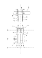
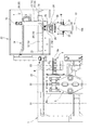
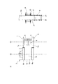
図1〜16は本発明に係る中空成形機の成形品取り出し装置(以下、単に「取り出し装置」と称する。)を実施するためのより具体的な形態を示している。特に図1は中空成形機1とそれに隣接配置された取り出し装置2のおよび搬送手段としてのベルトコンベヤ10の正面図を示し、図2は図1の要部の平面図を示している。また、図3は図1に示した中空成形機1での成形対象なる中空状の成形品Wの一例を示している。
FIGS. 1 to 16 show a more specific form for carrying out a molded product take-out device (hereinafter, simply referred to as “take-out device”) of the hollow molding machine according to the present invention. In particular, FIG. 1 shows a front view of the
図1,2では、中空成形機1の詳細は図示省略しているが、特許文献1(特開2014−65196号公報)に記載されたものと同様に、押出機のダイヘッドから押し出されたパリソンを前後一対の金型(成形金型)5a,5b同士の間に挟み込むパリソン挟み込みステージS1と、このパリソン挟み込みステージS1に隣接していて、上記一対の金型5a,5b同士の間に挟み込んだパリソンに対して図示を省略したエア吹き込みノズルにて圧縮エアを吹き込んで所定の中空状の成形品形状に成形(腑形)するエア吹き込みステージS2と、このエア吹き込みステージS2を挟んでパリソン挟み込みステージS1とは反対側に位置する受け渡しステージS3と、がそれぞれ設定されている。
Although the details of the
また、図1,2に示した中空成形機1での成形品対象となる成形品(製品)Wは、図3に示すように、平面形状が長方形をなす角形ボトル状のものであり、胴部Bの上部に、把手部Gと、ネック部Nと、が一体的に形成されている。
Further, as shown in FIG. 3, the molded product (product) W to be molded by the
図1,2に示すように、一対の金型5a,5bは、それぞれに独立した前後一対のプラテン4a,4bに固定されていて、双方のプラテン4a,4bは型締め装置3に支持されている。型締め装置3の作動により、一対のプラテン4a,4b同士が接近離間動作すると、それに伴って金型5a,5b同士が型締め,型開き動作するようになっている。同時に、一対の金型5a,5bとプラテン4a,4bを含む型締め装置3は、図示を省略した型締スライド機構の作動により、パリソン挟み込みステージS1とエア吹き込みステージS2との間でシフト動作するようになっている。
As shown in FIGS. 1 and 2, the pair of
また、図1,2に示すように、一対のプラテン4a,4bの側面には、側方に向かって突出する成形品ホルダ6,7が設けられている。これら一対の成形品ホルダ6,7は、それぞれのホルダ本体6a,7aから下方に延びていて且つ側面視にて略L字状の下部製品ホルダ8と、それぞれのホルダ本体6a,7aから上方に延びていて且つ側面視にて略L字状の上部製品ホルダ9と、を有している。これら双方の成形品ホルダ6,7の下部製品ホルダ8同士および上部製品ホルダ9同士は互いに対向している。
Further, as shown in FIGS. 1 and 2, molded
なお、図1に示されている各一対の下部製品ホルダ8と上部製品ホルダ9は、同じ正面図である図5,7,9,11では、図面の錯綜化を避けるために意図的に図示を省略している。また、図1に示すように、一方の成形品ホルダ6の下部製品ホルダ8と上部製品ホルダ9とを含む全体の形状は、成形品Wの輪郭形状よりも一回り小さな相似形をなしている。
The pair of
そして、図9に基づいて後述するように、一対の金型5a,5bとプラテン4a,4bとを含む型締め装置3がパリソン挟み込みステージS1にある状態で、一対の金型5a,5bがパリソンを挟み込むように型締め動作すると、一対の成形品ホルダ6,7は各プラテン4a,4bの動きに連動して、隣りのエア吹き込みステージS2にある一つ前の成形サイクルでの成形品Wを挟み込むようにして支持することになる。さらに、一対の金型5a,5bとプラテン4a,4bとを含む型締め装置3がパリソン挟み込みステージS1からエア吹き込みステージS2にシフト動作すると、図11に示すように、各プラテン4a,4bに付帯している一対の成形品ホルダ6,7は、支持している一つ前の成形サイクルでの成形品Wと共に受け渡しステージS3にシフト動作することになる。
Then, as will be described later based on FIG. 9, the pair of
なお、一対の成形品ホルダ6,7が成形品Wを支持する際には、双方の成形品ホルダ6,7同士の接近動作により、各下部製品ホルダ8が成形品Wの底面の下側に入り込んで下方から成形品Wを支えると共に、双方の上部製品ホルダ9同士が成形品Wのネック部Nを掴むことになる。
When the pair of molded
エア吹き込みステージS2には、図示を省略した昇降式のエア吹き込みノズルが設けられている。そして、パリソンを挟み込んだ一対の金型5a,5bを含む型締め装置3がエア吹き込みステージS2までシフト動作すると、エア吹き込みノズルがパリソンに差し込まれ、パリソンに圧縮エアが吹き込まれる。これにより、パリソンは所定の成形品形状に成形(腑形)されることになる。エア吹き込み完了後に、一対の金型5a,5bが型開き動作した上で型締め装置3が元のパリソン挟み込みステージS1に向かってシフト動作する際には、エア吹き込み完了後の成形品Wは一対の金型5a,5bから解放されて、エア吹き込みノズルにより吊り下げ状態で当該エア吹き込みノズルに支持されることになる。
The air blowing stage S2 is provided with an elevating type air blowing nozzle (not shown). Then, when the
なお、先にも説明したように、エア吹き込みステージS2において、一対の成形品ホルダ6,7がエア吹き込み完了後の成形品Wを支持すると、図示外のエア吹き込みノズルが上昇動作してエア吹き込み完了後の成形品Wから抜き取られることになる。
As described above, when the pair of molded
したがって、パリソン挟み込みステージS1およびエア吹き込みステージS2での一連の動作としては、パリソン挟み込みステージS1において一対の金型5a,5bの型締め動作によりパリソンを挟み込むと、隣りのエア吹き込みステージS2では、同時に、エア吹き込みステージS2にてエア吹き込みを終えた成形品Wが一対の成形品ホルダ6,7に支持される。そして、パリソンを挟み込んだ一対の金型5a,5bが型締め装置3ごとパリソン挟み込みステージS1から隣のエア吹き込みステージS2に向かってシフト動作すると、同時に、一対の成形品ホルダ6,7に支持されている成形品Wは、エア吹き込みステージS2からさらに隣りの受け渡しステージS3に向かってシフト動作することになる。
Therefore, as a series of operations in the parison sandwiching stage S1 and the air blowing stage S2, when the parison is sandwiched by the mold clamping operation of the pair of
図1に示すように、中空成形機1に隣接して、その右隣りに取り出し装置2が配置されている。また、取り出し装置2の下方には搬送手段としてのベルトコンベヤ10が配置されている。図2に示すように、平面視における一対の金型5a,5b同士のパーティングラインをPLとすると、平面視にてパーティングラインPLの延長線方向と直交するようにベルトコンベヤ10が配置されている。
As shown in FIG. 1, the take-out
図1に示した取り出し装置2は、後述するように、水平方向(パーティングラインPLの延長線方向と同じX方向)にスライド移動可能なX軸スライダ13を主要素とするX軸スライド装置11と、上下方向(鉛直方向であるZ方向)にスライド移動可能なZ軸スライダ17を主要素とするZ軸スライド装置15と、鉛直軸心周りの旋回可能な旋回ヘッド21を有する旋回ユニット19と、の組み合わせにより構成されている。その結果として、取り出し装置2は、水平方向および上下方向の直交二軸の動作自由度と、鉛直軸心周りの旋回一軸の動作自由度と、を有している。そして、取り出し装置2は、中空成形機1で成形された成形品Wを外部に取り出すアンローディング装置(アンローダ)としての機能を有するものである。
As will be described later, the take-out
図1に示すように、中空成形機1の機枠(フレーム)22から水平方向に片持ち式の支持ビーム23が張り出していて、この支持ビーム23に水平なX軸スライドユニット12が固定されている。このX軸スライドユニット12には、当該X軸スライドユニット12に沿って水平方向(X方向)にスライド移動可能なX軸スライダ13が支持されている。このX軸スライダ13は、X軸スライドユニット12に設けられたサーボモータ14で駆動される図示外のボールねじと内蔵されたガイドレールを介して、Z軸スライドユニット16を水平方向にスライド移動させることになる。したがって、水平なX軸スライドユニット12とX軸スライダ13およびその駆動系等によりX軸スライド装置11が構成されている。
As shown in FIG. 1, a cantilever
また、図1に示すように、X軸スライダ13には水平なX軸スライドユニット12に対して直交する鉛直なZ軸スライドユニット16が固定されている。このZ軸スライドユニット16には、当該Z軸スライドユニット16に沿って上下方向(Z方向)にスライド移動可能なZ軸スライダ17が支持されている。このZ軸スライダ17は、Z軸スライドユニット16に設けられたサーボモータ18で駆動される図示外のボールねじと内蔵されたガイドレールを介して、Z軸スライドユニット16に沿って上下方向にスライド移動することになる。したがって、鉛直なZ軸スライドユニット16とZ軸スライダ17およびその駆動系等によりZ軸スライド装置15が構成されている。
Further, as shown in FIG. 1, a vertical Z-
さらに、Z軸スライダ17には旋回ユニット19が設けられている。この旋回ユニット19は、Z軸スライダ17に固定されたベース部20の下側に、旋回ヘッド21が鉛直軸心周りに旋回可能に支持されている。この旋回ヘッド21は、例えばベース部20に配置された一対のエアシリンダの伸縮作動に応じて、90度毎の正転駆動と逆転駆動が可能となっている。なお、この旋回ユニット19は一例にすぎず、例えばエアモータタイプのものや電動モータタイプのものを使用しても良く、さらに旋回角度も90度に限定されることなく、任意の角度を選択可能である。
Further, the Z-
図1,2に示すように、旋回ユニット19の旋回ヘッド21には、いわゆる二指把持タイプのグリッパ装置24が装着されている。このグリッパ装置24は、後述する図9に示すように、直動型のアクチュエータとして機能するエアシリンダユニット25と、このエアシリンダユニット25を挟んでその両側に対向配置された一対の支持アーム26と、各支持アーム26から中空成形機1側に向かって張り出して互いに平行なバー状のフィンガー27と、一対のフィンガー27同士の対向内面に装着された軟質なパッド28と、から構成されている。
As shown in FIGS. 1 and 2, a so-called two-finger gripping
図9に示すように、エアシリンダユニット25は、ボディ29の両側から突出している一対のロッド部材29aが互いに独立していて、それら一対のロッド部材29aがボディ29に対して互いに逆向きに伸縮動作する構造のものである。そのため、エアシリンダユニット25の作動に応じて、一対のフィンガー27同士が一対の支持アーム26と共に接近離間動作、すなわち把持動作(クランプ)とその解放動作(アンクランプ)とを行うことができるようになっている。
As shown in FIG. 9, in the
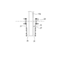
以上により、取り出し装置2は、水平なX軸スライドユニット12に沿ったX軸スライダ13のスライド自由度と、鉛直なZ軸スライドユニット16に沿ったZ軸スライダ17のスライド自由度と、旋回ユニット19における旋回ヘッド21の延長軸心周りの旋回自由度と、により、直交二軸と旋回一軸の動作自由度を有している。
As described above, the take-out
図4は図1に示した搬送手段としてのベルトコンベヤ10の拡大図を示している。このベルトコンベヤ10は、一対のベルトプーリ同士の間に搬送路となるエンドレスのコンベヤベルト10aが巻き掛けられた公知の構造のものである。そして、コンベヤベルト10aの両側には、ベルトコンベヤ10それ自体の非可動部分から延長形成したブラケット30およびポスト31を介して、複数のガイド部材32が長手方向に沿って設けられている。これらのガイド部材32は、図13〜15に示すように、ベルトコンベヤ10のコンベヤベルト10aにて搬送される成形品Wを両側から案内する役目をする。
FIG. 4 shows an enlarged view of the
なお、図4以外では、ベルトコンベヤ10に付帯する上記ガイド部材32の図示を省略している。また、図1において、符号33は透明板を主要素とした安全カバーで、この安全カバー33は取り出し装置2を覆っている。さらに、符号34はケーブル案内装置(商品名:ケーブルベヤ(登録商標))で、中空成形機1側と取り出し装置2側とを接続しているエアホースや電気ケーブルを案内する機能を有している。
In addition to FIG. 4, the
次に、上記のように構成された取り出し装置2の一連の動きを、図1〜4のほか、図5以下の図面を参照しながら詳しく説明する。
Next, a series of movements of the take-out
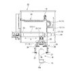
図1に示した中空成形機1で成形された成形品Wの取り出しに取り出し装置2が関与しない時には、取り出し装置2の可動部は同図に示した後退位置を原点位置として待機している。すなわち、X軸スライダ13は図1に示した後退位置にあり、Z軸スライダ17は図1に示した上昇位置にある。そして、中空成形機1での成形サイクルが繰り返されて、成形後の成形品Wが受け渡しステージS3まで搬送されてくると、取り出し装置2の可動部は図1の後退位置から図5に示す前進位置まで前進動作する。
When the take-out
すなわち、先にも説明したように、成形品ホルダ6,7に把持されている成形品Wがエア吹き込みステージS2から受け渡しステージS3まで搬送されてくると、それよりも遅れて取り出し装置2の可動部が図5に示した前進位置まで前進動作する。
That is, as described above, when the molded product W held by the molded
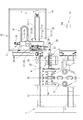
この取り出し装置2の可動部の前進動作は、グリッパ装置24の一対のフィンガー27が、成形品ホルダ6,7と干渉せずに且つその成形品ホルダ6,7に支持されている成形品Wを把持可能な位置まで進入することを意味する。そして、グリッパ装置24の一対のフィンガー27同士は前進位置にて直ちにクランプ動作して、図5,6に示すように、成形品Wの胴部B(図3参照)を把持する。つまり、図5,6に示すように、一対の成形品ホルダ6,7に支持されている成形品Wは、同時にグリッパ装置24の一対のフィンガー27によっても把持される。
In the forward movement of the movable portion of the take-out
グリッパ装置24の一対のフィンガー27が成形品Wを把持すると、図7,8に示すように、エア吹き込みステージS2での一対の金型5a,5b同士の型開き動作に連動して、一対の成形品ホルダ6,7同士が離間して、成形品Wを解放する。その一方、一対のフィンガー27が成形品Wを把持している取り出し装置2の可動部は、直ちに図7,8に示す後退位置まで戻る。
When the pair of
続いて、図9,10に示すように、型開き状態にある一対の金型5a,5bは、型締め装置3ごとエア吹き込みステージS2からパリソン挟み込みステージS1にシフト動作すると共に、それに連動して、一対の成形品ホルダ6,7は受け渡しステージS3からエア吹き込みステージS2にシフト動作する。パリソン挟み込みステージS1にシフト動作した一対の金型5a,5bは、型締め動作によりパリソンを挟み込む。同時に、一対の金型5a,5bの型締め動作に連動して、エア吹き込みステージS2では、圧縮エアの吹き込みにより成形(腑形)された成形品Wが一対の成形品ホルダ6,7で支持される。
Subsequently, as shown in FIGS. 9 and 10, the pair of
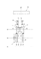
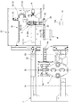
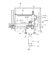
パリソン挟み込みステージS1およびエア吹き込みステージS2での上記動作と並行して、後退位置に戻った取り出し装置2では、X軸スライダ13およびZ軸スライダ17はその位置にとどまったままで、図8の状態から図10の状態へと、旋回ユニット19における旋回ヘッド21が反時計回り方向に90度旋回動作する。この旋回ヘッド21の旋回動作に伴い、グリッパ装置24の一対のフィンガー27に把持されている成形品Wもグリッパ装置24と共に同方向に90度旋回動作する。このように、一対のフィンガー27に把持されている成形品Wがグリッパ装置24と共に90度旋回動作することにより、グリッパ装置24におけるフィンガー27の長手方向がベルトコンベヤ10による搬送方向と一致することになる。
In the take-out
続いて、図11,12に示すように、パリソン挟み込みステージS1にてパリソンを挟み込んだ一対の金型5a,5bが型締め装置3ごとエア吹き込みステージS2にシフト動作し、圧縮エアの吹き込みによる成形(腑形)が行われる。それに連動して、先にエア吹き込みステージS2にて成形品Wを支持した一対の成形品ホルダ6,7が受け渡しステージS3にシフト動作する。
Subsequently, as shown in FIGS. 11 and 12, the pair of
その一方、図11,12に示した取り出し装置2側では、旋回ヘッド21が90度旋回動作すると、それに続いて、Z軸スライダ17が上昇位置から下降位置まで下降動作して停止する。この段階では、グリッパ装置24の一対のフィンガー27に把持されている成形品Wがベルトコンベヤ10のコンベヤベルト10aに着底することはなく、コンベヤベルト10aからわずかに浮いた状態にある。
On the other hand, on the take-out
その後、図13,14に示すように、グリッパ装置24が解放動作して一対のフィンガー27が互いに離間することで、成形品Wがグリッパ装置24から解放されて、ベルトコンベヤ10のコンベヤベルト10aに移載される。その結果、成形品Wはベルトコンベヤ10により所定位置まで搬送される。
After that, as shown in FIGS. 13 and 14, the
この段階では、図11,12に示したエア吹き込みステージS2での圧縮エアの吹き込みによる成形(腑形)が継続されている。その一方、成形品Wを解放してベルトコンベヤ10側に移載し終えたグリッパ装置24は、図15,16に示すようにZ軸スライダ17ごと上昇位置に戻る。
At this stage, molding by blowing compressed air at the air blowing stage S2 shown in FIGS. 11 and 12 is continued. On the other hand, the
その後、取り出し装置2では、解放状態のグリッパ装置24が旋回ヘッド21ごと反時計回り方向に90度旋回動作して、図1,2に示した元の状態に戻る。そして、以降はこれまでに述べた一連の動作を繰り返すことになる。
After that, in the take-out
このように本実施の形態の取り出し装置2では、取り出し装置2そのものが直交二軸の動作自由度に加えて鉛直軸心周りの旋回自由度を有していて、中空成形機1から水平方向に取り出した成形品Wの向きを直ちに変更することができ、それに合わせるかたちで搬送手段であるベルトコンベヤ10の搬送方向を設定することができる。
As described above, in the take-out
このことは、中空成形機1から水平方向への成形品Wの取り出し方向と、ベルトコンベヤ10による平面視での成形品Wの搬送方向とを交差させることができることにほかならない。そのため、中空成形機1のほか、それに付帯することになる取り出し装置2およびベルトコンベヤ10を含んだ全体の設備設置スペースの縮小化を図ることができるようになる。
This means that the take-out direction of the molded product W from the
ここで、上記実施の形態では、図3に示したいわゆる角形ボトル状の成形品Wを例にとって説明したが、成形品Wの形状は特に限定されるものではない。また、成形品Wの搬送手段としてベルトコンベヤ10を例にとって説明したが、ベルトコンベヤ10に代えて、例えばローラコンベヤやスラットコンベヤ、あるいはシューター等を用いることも可能である。さらに、グリッパ装置24としては、二指把持タイプのものに限らず、他の形式のもの、例えば吸着カップ(吸着パッド)タイプのものでも対応することが可能である。
Here, in the above-described embodiment, the so-called square bottle-shaped molded product W shown in FIG. 3 has been described as an example, but the shape of the molded product W is not particularly limited. Further, although the
同様に、上記実施の形態では、パーティングラインPLの延長線方向に沿った成形品Wの取り出し方向(X方向)と、ベルトコンベヤ10による搬送方向と、が平面視にて直交している場合について説明したが、両者は必ずしも直交している必要はなく、交差しているならば所期の目的を達成することができ、それに併せて旋回ヘッド21の旋回角度が設定されることになる。
Similarly, in the above embodiment, when the take-out direction (X direction) of the molded product W along the extension line direction of the parting line PL and the transport direction by the
さらに、先に特許文献1として記載したものと同様に、複数の成形品Wが同時に成形されるタイプの中空成形機にも本発明を無理なく適用することができる。加えて、上記特許文献1として記載したものと同様に、上記受け渡しステージS3が、成形後の成形品Wから「ばり」を分離するばり分離ステージとなっていることもある。このような場合であっても、本発明を適用することができる。
Further, the present invention can be reasonably applied to a hollow molding machine of a type in which a plurality of molded products W are simultaneously molded, as in the case described in
1…中空成形機
2…成形品取り出し装置
5a,5b…金型
6,7…成形品ホルダ
10…ベルトコンベヤ(搬送手段)
10a…コンベヤベルト(搬送路)
11…X軸スライド装置
12…X軸スライドユニット
13…X軸スライダ
15…Z軸スライド装置
16…Z軸スライドユニット
17…Z軸スライダ
19…旋回ユニット
21…旋回ヘッド
24…グリッパ装置
27…フィンガー
PL…パーティングライン
S1…パリソン挟み込みステージ
S2…エア吹き込みステージ
S3…受け渡しステージ
1 ...
10a ... Conveyor belt (conveyor path)
11 ...
Claims (2)
上記パーティングラインの延長線方向に延びる水平なガイドレールに沿って移動可能なX軸スライダと、
上記X軸スライダに設けられた鉛直なガイドレールに沿って移動可能なZ軸スライダと、
上記Z軸スライダに設けられていて、鉛直軸心周りに旋回可能な旋回ヘッドと、
上記旋回ヘッドに設けられていて、上記中空成形機で成形された成形品を把持するグリッパ装置と、
を備えていると共に、
上記搬送手段は平面視において上記パーティングラインの延長線方向と交差する方向の搬送路を有していて、
上記グリッパ装置が把持した上記成形品を上記機外に取り出すと共に、
上記旋回ヘッドの動作自由度を使って上記グリッパ装置が把持している上記成形品の姿勢を変更した上で、上記搬送手段の搬送路に移載するようになっていることを特徴とする中空成形機の成形品取り出し装置。 A molded product molded by a hollow molding machine having a pair of molds capable of mold clamping and mold opening operations is synchronized with the molding cycle in the direction of the extension of the parting line in the plan view of the pair of molds. It is a molded product take-out device of a hollow molding machine that is taken out of the machine along the line and then transferred to a transport means.
An X-axis slider that can be moved along a horizontal guide rail that extends in the direction of the extension of the parting line,
A Z-axis slider that can be moved along a vertical guide rail provided on the X-axis slider,
A swivel head provided on the Z-axis slider that can swivel around the vertical axis,
A gripper device provided on the swivel head and grips a molded product molded by the hollow molding machine, and a gripper device.
Along with
The transport means has a transport path in a direction intersecting the extension direction of the parting line in a plan view.
While taking out the molded product gripped by the gripper device to the outside of the machine,
The hollow is characterized in that the posture of the molded product held by the gripper device is changed by using the degree of freedom of operation of the swivel head, and then the molded product is transferred to the transport path of the transport means. Molded product take-out device for molding machines.
上記中空成形機は、
押出機の先端のダイヘッドから押し出されたパリソンを上記一対の金型間に挟み込むパリソン挟み込みステージと、
上記パリソン挟み込みステージに隣接していて、上記一対の金型間に挟み込んだパリソンに対してエア吹き込みノズルにて圧縮エアを吹き込むエア吹き込みステージと、
上記エア吹き込みステージを挟んで上記パリソン挟み込みステージとは反対側に設定された受け渡しステージと、
を有していて、
上記一対の金型が上記パリソン挟み込みステージと上記エア吹き込みステージとの間を往復移動するようになっていると共に、
上記一対の金型の型締め,型開き動作に連動して上記成形品を把持することが可能な成形品ホルダーが、上記一対の金型の往復移動に連動して、上記エア吹き込みステージと上記受け渡しステージとの間を往復移動するようになっていて、
上記グリッパ装置は上記受け渡しステージにある上記成形品を把持するようになっていることを特徴とする中空成形機の成形品取り出し装置。 In the molded product take-out device of the hollow molding machine according to claim 1.
The above hollow molding machine
A parison sandwiching stage that sandwiches the parison extruded from the die head at the tip of the extruder between the pair of molds.
An air blowing stage that is adjacent to the parison sandwiching stage and blows compressed air into the parison sandwiched between the pair of molds with an air blowing nozzle.
The delivery stage set on the opposite side of the parison sandwiching stage with the air blowing stage in between,
Have
The pair of molds reciprocate between the parison sandwiching stage and the air blowing stage, and
The molded product holder capable of gripping the molded product in conjunction with the mold tightening and mold opening operations of the pair of molds is linked to the reciprocating movement of the pair of molds, and the air blowing stage and the above. It is designed to move back and forth between the delivery stage and
The gripper device is a molded product take-out device for a hollow molding machine, characterized in that it grips the molded product on the delivery stage.
Priority Applications (1)
| Application Number | Priority Date | Filing Date | Title |
|---|---|---|---|
| JP2019053396A JP7240219B2 (en) | 2019-03-20 | 2019-03-20 | hollow molding machine |
Applications Claiming Priority (1)
| Application Number | Priority Date | Filing Date | Title |
|---|---|---|---|
| JP2019053396A JP7240219B2 (en) | 2019-03-20 | 2019-03-20 | hollow molding machine |
Publications (2)
| Publication Number | Publication Date |
|---|---|
| JP2020152014A true JP2020152014A (en) | 2020-09-24 |
| JP7240219B2 JP7240219B2 (en) | 2023-03-15 |
Family
ID=72557267
Family Applications (1)
| Application Number | Title | Priority Date | Filing Date |
|---|---|---|---|
| JP2019053396A Active JP7240219B2 (en) | 2019-03-20 | 2019-03-20 | hollow molding machine |
Country Status (1)
| Country | Link |
|---|---|
| JP (1) | JP7240219B2 (en) |
Cited By (1)
| Publication number | Priority date | Publication date | Assignee | Title |
|---|---|---|---|---|
| CN112571694A (en) * | 2020-11-24 | 2021-03-30 | 江西美宝利实业有限公司 | Automatic glove remainder removing device |
Citations (5)
| Publication number | Priority date | Publication date | Assignee | Title |
|---|---|---|---|---|
| US3981667A (en) * | 1974-07-26 | 1976-09-21 | Monsanto Company | Takeout apparatus for a blow molding machine |
| JP2002361723A (en) * | 2001-06-01 | 2002-12-18 | Nissei Asb Mach Co Ltd | Blow molding equipment |
| JP2003103616A (en) * | 2001-09-28 | 2003-04-09 | Tahara:Kk | Removal method of hollow molded product in hollow molding method |
| JP2007526189A (en) * | 2004-03-05 | 2007-09-13 | スィデル・パルティスィパスィヨン | Transport device with improved transport arm |
| JP2009018581A (en) * | 2007-06-28 | 2009-01-29 | Sidel Participations | Article transfer device having transfer arm with gripping head movable substantially vertically |
-
2019
- 2019-03-20 JP JP2019053396A patent/JP7240219B2/en active Active
Patent Citations (5)
| Publication number | Priority date | Publication date | Assignee | Title |
|---|---|---|---|---|
| US3981667A (en) * | 1974-07-26 | 1976-09-21 | Monsanto Company | Takeout apparatus for a blow molding machine |
| JP2002361723A (en) * | 2001-06-01 | 2002-12-18 | Nissei Asb Mach Co Ltd | Blow molding equipment |
| JP2003103616A (en) * | 2001-09-28 | 2003-04-09 | Tahara:Kk | Removal method of hollow molded product in hollow molding method |
| JP2007526189A (en) * | 2004-03-05 | 2007-09-13 | スィデル・パルティスィパスィヨン | Transport device with improved transport arm |
| JP2009018581A (en) * | 2007-06-28 | 2009-01-29 | Sidel Participations | Article transfer device having transfer arm with gripping head movable substantially vertically |
Cited By (2)
| Publication number | Priority date | Publication date | Assignee | Title |
|---|---|---|---|---|
| CN112571694A (en) * | 2020-11-24 | 2021-03-30 | 江西美宝利实业有限公司 | Automatic glove remainder removing device |
| CN112571694B (en) * | 2020-11-24 | 2022-08-19 | 江西美宝利实业有限公司 | Automatic glove remainder removing device |
Also Published As
| Publication number | Publication date |
|---|---|
| JP7240219B2 (en) | 2023-03-15 |
Similar Documents
| Publication | Publication Date | Title |
|---|---|---|
| KR101914436B1 (en) | Mold treatment device for glass molding | |
| US20010033876A1 (en) | Resin molding machine and resin tablet feeding machine | |
| KR101865094B1 (en) | A manufacturing apparatus for a container comprising 3d shape | |
| JP2020152014A (en) | Molded product take-out device for hollow molding machines | |
| CN102272027A (en) | Method and apparatus for transferring workpieces | |
| KR20180088851A (en) | Blow molding apparatus and blow molding method | |
| JPH0615200B2 (en) | Method and apparatus for forming stretch-blown hollow container with label | |
| CN205097520U (en) | Duplex position automatic rotary blowing machine's improvement structure | |
| JPH1058457A5 (en) | ||
| CN201530119U (en) | Plastic hot forming machine | |
| CN100503211C (en) | Reciprocating opening preform or molded bottle pick-up and delivery device | |
| JP2001334567A (en) | Method and apparatus for blow molding | |
| CN222959176U (en) | A bottle embryo seat conveying device | |
| JP3510936B2 (en) | Molding equipment | |
| JPH11105114A (en) | Method for transporting preform and preform mounting member used for this method | |
| US8613882B2 (en) | Method of planting a handle and a bottle parison to a mold of blow-molding modules for manufacturing plastic containers | |
| CN217258325U (en) | Automatic demoulding mechanism of injection blow hollow forming machine | |
| JPS63132012A (en) | Robot apparatus for putting-in and taking-out of work | |
| JP2003103616A (en) | Removal method of hollow molded product in hollow molding method | |
| JP3847143B2 (en) | Hollow molding machine | |
| TWM414321U (en) | Hollow forming machine | |
| JP2007276327A (en) | Biaxial stretching blow molding machine | |
| CN209381271U (en) | Dynamic fixed mold automatic labeling machine | |
| JP2002301745A (en) | Molded product recovery system in injection molding machine | |
| JP3777200B2 (en) | Molding device and feeding device |
Legal Events
| Date | Code | Title | Description |
|---|---|---|---|
| A621 | Written request for application examination |
Free format text: JAPANESE INTERMEDIATE CODE: A621 Effective date: 20220216 |
|
| A977 | Report on retrieval |
Free format text: JAPANESE INTERMEDIATE CODE: A971007 Effective date: 20221118 |
|
| A131 | Notification of reasons for refusal |
Free format text: JAPANESE INTERMEDIATE CODE: A131 Effective date: 20221122 |
|
| A521 | Request for written amendment filed |
Free format text: JAPANESE INTERMEDIATE CODE: A523 Effective date: 20230119 |
|
| TRDD | Decision of grant or rejection written | ||
| A01 | Written decision to grant a patent or to grant a registration (utility model) |
Free format text: JAPANESE INTERMEDIATE CODE: A01 Effective date: 20230207 |
|
| A61 | First payment of annual fees (during grant procedure) |
Free format text: JAPANESE INTERMEDIATE CODE: A61 Effective date: 20230303 |
|
| R150 | Certificate of patent or registration of utility model |
Ref document number: 7240219 Country of ref document: JP Free format text: JAPANESE INTERMEDIATE CODE: R150 |