JP2020152257A - Body parts - Google Patents
Body parts Download PDFInfo
- Publication number
- JP2020152257A JP2020152257A JP2019053191A JP2019053191A JP2020152257A JP 2020152257 A JP2020152257 A JP 2020152257A JP 2019053191 A JP2019053191 A JP 2019053191A JP 2019053191 A JP2019053191 A JP 2019053191A JP 2020152257 A JP2020152257 A JP 2020152257A
- Authority
- JP
- Japan
- Prior art keywords
- vehicle body
- body member
- curved portion
- curvature
- radius
- Prior art date
- Legal status (The legal status is an assumption and is not a legal conclusion. Google has not performed a legal analysis and makes no representation as to the accuracy of the status listed.)
- Granted
Links
Images


Classifications
-
- Y—GENERAL TAGGING OF NEW TECHNOLOGICAL DEVELOPMENTS; GENERAL TAGGING OF CROSS-SECTIONAL TECHNOLOGIES SPANNING OVER SEVERAL SECTIONS OF THE IPC; TECHNICAL SUBJECTS COVERED BY FORMER USPC CROSS-REFERENCE ART COLLECTIONS [XRACs] AND DIGESTS
- Y02—TECHNOLOGIES OR APPLICATIONS FOR MITIGATION OR ADAPTATION AGAINST CLIMATE CHANGE
- Y02T—CLIMATE CHANGE MITIGATION TECHNOLOGIES RELATED TO TRANSPORTATION
- Y02T30/00—Transportation of goods or passengers via railways, e.g. energy recovery or reducing air resistance
Landscapes
- Body Structure For Vehicles (AREA)
Abstract
【課題】より軽量で、かつ高い軸方向圧縮耐力を確保可能な車体部材を提供する。
【解決手段】板厚が1.6mm以下である鋼板により形成され、曲率半径が最大である基準湾曲部の端に連続する長い基準平面部の両端のうち基準平面部が連続しないほうの端から基準湾曲部の接線方向に延びる直線を第1直線とし、基準平面部の延長線を第2直線とし、第1直線と第2直線の交点と、基準平面部の両端のうち基準湾曲部に連続しないほうの端と、の間の長さをb0とし、基準平面部の長さをb1とし、基準湾曲部の曲率半径をRとするとき、以下の式(1)および式(2)を満足する。

【選択図】図1PROBLEM TO BE SOLVED: To provide a vehicle body member which is lighter and can secure a high axial compression strength.
SOLUTION: From both ends of a long reference plane portion formed of a steel plate having a plate thickness of 1.6 mm or less and continuous with the end of a reference curved portion having the maximum radius of curvature, the end where the reference plane portion is not continuous The straight line extending in the tangential direction of the reference curved portion is the first straight line, the extension line of the reference plane portion is the second straight line, the intersection of the first straight line and the second straight line, and both ends of the reference plane portion are continuous with the reference curved portion. The following equations (1) and (2) are satisfied when the length between the non-end and the end is b0, the length of the reference plane portion is b1, and the radius of curvature of the reference curved portion is R. To do.
[Selection diagram] Fig. 1
Description
本発明は、例えば自動車用の車体部材に関する。 The present invention relates to, for example, vehicle body members for automobiles.
従来、車体部材として、鋼板を材料として形成され所定の断面形状を有する中空部材が用いられている。これらの車体部材は、軽量化を実現するとともに、十分な耐荷重を有することが求められる。このため、近年、高い強度を有する高張力鋼板が材料として使用されることがある。 Conventionally, as a vehicle body member, a hollow member formed of a steel plate as a material and having a predetermined cross-sectional shape has been used. These vehicle body members are required to be lightweight and have a sufficient load capacity. Therefore, in recent years, a high-strength steel sheet having high strength may be used as a material.
車体に対して衝突等による衝撃が加えられる場合には、車体部材は軸方向の圧縮荷重を受け得る。車体部材の十分な耐荷重を実現するためには、車体部材の高い軸方向圧縮耐力を確保し、例えば座屈を抑制することが求められる。下記の特許文献1には、軸方向圧縮曲げ変形を被る車体構造用部材において、より軽量で、軸方向圧縮曲げ強度が高い部材を実現するため、圧縮変形を受ける面を外側に凸に湾曲させる技術が記載されている。
When an impact such as a collision is applied to the vehicle body, the vehicle body member can receive a compressive load in the axial direction. In order to realize a sufficient load capacity of the vehicle body member, it is required to secure a high axial compressive strength of the vehicle body member and suppress buckling, for example. In
上記特許文献1に記載の技術は、部材の断面形状のうち、圧縮変形を受ける面の形状を外側に凸に湾曲させるのみであり、湾曲面に連続する平面も含めた断面形状が部材全体の軸方向圧縮耐力に与える影響を考慮していない。また、車体構造用部材に使用する材料の薄肉化・高強度化は、当該部材の弾性座屈応力を低下させうる。このため、軸方向圧縮荷重を受ける部位において、材料の降伏応力に到達する前に弾性座屈が生じるおそれがあり、これにより軸方向圧縮耐力が低下するおそれがある。しかし、上記特許文献1に記載の技術を含め、従来の技術は、このような観点から車体部材の断面形状を設定するものではなかった。
The technique described in
そこで、本発明は、上記問題に鑑みてなされたものであり、本発明の目的とするところは、より軽量で、かつ高い軸方向圧縮耐力を確保可能な、新規かつ改良された車体部材を提供することにある。 Therefore, the present invention has been made in view of the above problems, and an object of the present invention is to provide a new and improved vehicle body member which is lighter and can secure a high axial compression strength. To do.
上記課題を解決するために、本発明のある観点によれば、板厚が1.6mm以下である鋼板により形成され、軸直角方向断面の形状が、外側または内側に凸の少なくとも1つの湾曲部と、少なくとも1つの平面部とを有し、曲率半径が最大である1つの湾曲部を基準湾曲部とし、基準湾曲部の長手方向両端のうち、一端のみに平面部が連続する場合は当該平面部、両端に平面部が連続する場合は当該平面部のうち長いほうの平面部を、それぞれ基準平面部とし、基準湾曲部の長手方向両端のうち基準平面部が連続しないほうの端から基準湾曲部の接線方向に延びる直線を第1直線とし、基準平面部の延長線を第2直線とし、第1直線と第2直線の交点と、基準平面部の長手方向両端のうち基準湾曲部に連続しないほうの端と、の間の長さをb0とし、基準平面部の長さをb1とし、基準湾曲部の曲率半径をRとするとき、以下の式(1)および式(2)を満足する、車体部材が提供される。ただし、基準平面部を形成する部分の鋼板の、板厚をt、ヤング率をE、ポアソン比をν、降伏応力をσyとする。
上記鋼板の引張強度が1180MPa以上であってもよい。 The tensile strength of the steel sheet may be 1180 MPa or more.
上記Rが15mm以上であってもよい。 The R may be 15 mm or more.
上記b1が10mm以上であってもよい。 The b1 may be 10 mm or more.
上記基準湾曲部を間に挟んで第1直線と第2直線がなす角度が80°以上、150°以下であってもよい。 The angle formed by the first straight line and the second straight line with the reference curved portion sandwiched between them may be 80 ° or more and 150 ° or less.
上記軸直角方向断面が、閉断面であってもよい。 The cross section in the direction perpendicular to the axis may be a closed cross section.
以上説明したように本発明によれば、より軽量で、かつ高い軸方向圧縮耐力を確保可能な車体部材が提供される。 As described above, according to the present invention, there is provided a vehicle body member that is lighter and can secure a high axial compression strength.
以下に添付図面を参照しながら、本発明の好適な実施の形態について詳細に説明する。なお、本明細書及び図面において、実質的に同一の機能構成を有する構成要素については、同一の符号を付することにより重複説明を省略する。 A preferred embodiment of the present invention will be described in detail below with reference to the accompanying drawings. In the present specification and the drawings, components having substantially the same functional configuration are designated by the same reference numerals, so that duplicate description will be omitted.
<第1の実施形態>
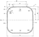
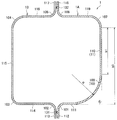
まず、図1を参照して、第1の実施形態の構成について説明する。図1は、本実施形態に係る車体部材の一例を示す断面図である。車体部材1は、車体の構造部材、言い換えると骨格部材であってよい。車体は、例えば自動車の車体であってよい。車体部材1は、鋼板により形成された、例えば中空筒状の部材である。以下、車体部材1の軸に沿う長手方向を軸方向ともいう。車体部材1の材料となる鋼板は特に限定されないが、その引張強度が1180MPa以上であってもよい。なお、引張強度は、1.2GPa級に限らず、1.5GPa級、1.8GPa級、2.5GPa級等であってよい。該鋼板の板厚が1.6mm以下である場合に、本実施形態に係る車体部材1による後述の効果が発揮される。なお、鋼板の板厚は、車体部材1に求められる衝撃吸収特性等の観点から、例えば0.4mm以上であってよい。車体部材1は、鋼板に対し公知の種々の加工技術を適用することにより、形成され得る。一例として、ブランク材が、冷間絞りプレス加工により所定の形状に成形されることで、車体部材1が形成されてもよい。また、車体部材1は、例えば、ホットスタンプにより形成されてもよい。
<First Embodiment>
First, the configuration of the first embodiment will be described with reference to FIG. FIG. 1 is a cross-sectional view showing an example of a vehicle body member according to the present embodiment. The
車体部材1は、一例として、角管状であってよい。図1は、角管状である車体部材1の、軸方向に直交する断面(軸直角方向断面)を示す。車体部材1の軸直角方向断面は、閉断面であり、4つの湾曲部100,101,102,103と、4つの平面部110,111,112,113とを有する。湾曲部100,101,102,103は、車体部材1の外側に凸の円弧状であり、互いに同じ形状および大きさであってよい。平面部110,111,112,113は、直線状であり、互いに同じ大きさであってよい。
As an example, the
湾曲部100,101,102,103のうち、曲率半径が最大である1つの湾曲部を基準湾曲部10とする。ここで湾曲部の曲率半径は、例えば、以下のようにして得られる。すなわち、軸直角方向断面において、車体部材1の表面における鋼板の曲げの始点または終点(言い換えると曲線と直線との境界点)である2つのR止まり点と、上記表面のうち湾曲部において上記2つのR止まり点から上記表面に沿って等距離に位置する曲げ中央点と、の3点を求める。これら3点から公知の数学的手法により曲率を求めることで、当該湾曲部の曲率半径が得られる。なお、上記表面は、図1に示すように鋼板の曲げ外側の表面である。図1に示す例では、湾曲部100,101,102,103の曲率半径は互いに同じであるため、例えば湾曲部100を基準湾曲部10とすることができる。また、基準湾曲部10の曲率半径をRとする。
Of the
軸直角方向断面において、基準湾曲部10の長手方向両端P,Qに、それぞれ平面部110,113が連続する。これら両端P,Qは、車体部材1の表面における上記2つのR止まり点である。平面部110,113のうち長いほうの平面部を基準平面部11とする。図1に示す例では、平面部110,113の長さは互いに同じであるため、例えば平面部110を基準平面部11とすることができる。なお、基準湾曲部10の長手方向両端P,Qのうち一端のみに平面部が連続する場合は、当該平面部を基準平面部11としてよい。
In the cross section in the direction perpendicular to the axis, the
基準湾曲部10の長手方向両端P,Qのうち基準平面部11が連続しないほうの端Pから基準湾曲部10の接線方向に延びる直線、言い換えると端Pにおける基準湾曲部10の表面の接線を、第1直線L1とする。また、基準平面部11の表面(図1に示す例では、基準湾曲部10の曲げ外側の表面に連続する表面)の延長線を第2直線L2とする。
A straight line extending in the tangential direction of the
第1直線L1と第2直線L2の交点Sと、基準平面部11の長手方向両端Q,Tのうち基準湾曲部10に連続しないほうの端Tと、の間の長さをb0とする。
Let b0 be the length between the intersection S of the first straight line L1 and the second straight line L2 and the end T of both ends Q and T of the
基準湾曲部10を間に挟んで第1直線L1と第2直線L2がなす角度をθとする。θは、80°以上、150°以下の範囲内に設定されてよい。図1に示す例では、θは90°またはその近傍に設定されている。
Let θ be the angle formed by the first straight line L1 and the second straight line L2 with the reference curved
軸直角方向断面において、基準平面部11の、長さ(幅)をb1とし、板厚をtとし、ヤング率をEとし、ポアソン比をνとし、降伏応力をσyとする。このとき、基準湾曲部10の曲率半径Rは、以下の式(1)を満足するように設定される。なお、このように設定される曲率半径Rは、例えば、材料となる鋼板の引張強度が1180MPa以上である場合、15mm以上であってよい。また、曲率半径Rの上限値は特に限定されず、後述するように基準平面部11の長さb1が0超となるような曲率半径であればよい。
基準平面部11の長さb1は、以下の式(2)を満足するように設定される。なお、このように設定される長さb1は、式(2)を満たす範囲において、例えば10mm以上であってよい。
次に、本実施形態の作用効果を説明する。車体部材1には、軸方向の圧縮荷重(軸方向圧縮荷重)が作用しうる。車体部材1のうち、湾曲部100〜103に相当する部分は、その形状により、平面部110〜113に相当する部分に比べ、軸方向圧縮荷重に対して高い剛性を有しており、弾性座屈しにくい。よって、基準湾曲部10の曲率半径Rを所定値以上に設定する。これにより、この基準湾曲部10を挟む両側の平面部のうち、一方(例えば平面部110)が弾性座屈しようとしても、この変形が他方(例えば平面部113)へ及ぼす影響、すなわち平面部同士が連動して弾性座屈しようとすることが、基準湾曲部10により遮断されうる。よって、車体部材1の全体として、弾性座屈を抑制し、軸方向圧縮耐力を向上できる。具体的には、基準湾曲部10の曲率半径Rを、上記式(1)の左辺で規定される下限値以上に設定することで、上記影響を抑制し、車体部材1の全体の弾性座屈を抑制できる。曲率半径Rは、鋼板の引張強度が1180MPa以上である場合、例えば15mm以上であってよく、この場合、軸方向圧縮耐力を効果的に向上できることを、本発明者らは確かめた(後述の実施例1−1を参照)。
Next, the action and effect of this embodiment will be described. An axial compressive load (axial compressive load) can act on the
また、基準平面部11の長さb1を、上記式(2)の右辺で規定される上限値以下に設定することにより、基準湾曲部10に連続する平面部の弾性座屈を抑制できる。式(2)は、本発明者らが鋭意検討した結果得られた式である。かかる式(2)により、高強度かつ板厚が小さい鋼鈑から形成された車体部材1の軸方向圧縮荷重に対する変形モードを考慮した、平面部の有効最大長が算出される。ここで有効最大長は、軸直角方向断面において、平面部の長手方向の所定範囲(例えば全範囲)で弾性座屈応力が降伏応力以上となり、これにより弾性座屈が回避されるような、当該平面部の長さの上限値である。
Further, by setting the length b1 of the
基準平面部11の長さb1を有効最大長以下に設定することで、基準平面部の長手方向の所定範囲(例えば全範囲)で弾性座屈が抑制される。言い換えると、基準平面部の長手方向の所定範囲で、軸方向圧縮応力が材料の強さ限界に達するまでは、基準平面部に加えられる荷重は、材料の強さによって受け止められ、基準平面部の弾性座屈へと転換されにくい。基準湾曲部を両側で挟む2つの平面部のうち、基準平面部と反対側の平面部の長さは、基準平面部の定義上、基準平面部の長さ以下である。よって、この平面部の長さも、上記式(2)の右辺で規定される上限値以下となるため、当該平面部でも弾性座屈が抑制される。言い換えると、基準湾曲部を挟む両側の平面部で弾性座屈が抑制される。
By setting the length b1 of the
上記式(1)の左辺で規定される曲率半径Rの下限値は、長さb0から、平面部の有効最大長を減じた大きさである。言い換えると、基準平面部の長さを有効最大長以下としつつ、基準湾曲部の曲率半径Rを可及的に大きく確保できるように、当該曲率半径Rの下限値が設定されている。よって、基準湾曲部を挟む両側の平面部で弾性座屈を抑制できるとともに、仮にこれら平面部のいずれか一方が座屈しようとしても、これが他方の平面部へ及ぼし得る影響を、両平面部の間に介在する基準湾曲部により、遮断することができる。このように、曲率半径Rの下限値と長さb1の上限値との相乗効果により、車体部材1の全体として、軸方向圧縮耐力を向上させ、弾性座屈を抑制することができる。
The lower limit of the radius of curvature R defined by the left side of the above equation (1) is the size obtained by subtracting the effective maximum length of the flat surface portion from the length b0. In other words, the lower limit of the radius of curvature R is set so that the radius of curvature R of the reference curved portion can be secured as large as possible while keeping the length of the reference plane portion equal to or less than the effective maximum length. Therefore, elastic buckling can be suppressed in the plane portions on both sides of the reference curved portion, and even if one of these plane portions tries to buckle, the effect that this can have on the other plane portion is exerted on both plane portions. It can be blocked by a reference curved portion intervening between them. As described above, the synergistic effect of the lower limit value of the radius of curvature R and the upper limit value of the length b1 can improve the axial proof stress of the
第1直線L1と第2直線L2がなす角度θは、80°以上、150°以下であってよい。角度θが150°以下であることで、軸直角方向断面における平面部の長手方向端が、ある程度の角度をもって他部分により支持され、これにより、自由端とならずに単純支持されているとみなすことができる。よって、上記式(2)による基準平面部の有効最大長の規定が有効に機能し、長さb1が式(2)を満たすことによる上記作用効果を有効に得ることができる。また、角度θが80°以上であることで、基準湾曲部の曲率半径Rが式(1)を満たすことが容易となる。 The angle θ formed by the first straight line L1 and the second straight line L2 may be 80 ° or more and 150 ° or less. When the angle θ is 150 ° or less, the longitudinal end of the flat surface portion in the cross section in the direction perpendicular to the axis is supported by another portion at a certain angle, and thus it is considered that the end is simply supported without becoming a free end. be able to. Therefore, the definition of the effective maximum length of the reference plane portion by the above equation (2) functions effectively, and the above-mentioned action and effect can be effectively obtained by satisfying the equation (2) with the length b1. Further, when the angle θ is 80 ° or more, the radius of curvature R of the reference curved portion easily satisfies the equation (1).
車体部材1は、引張強度が所定値以上であって、板厚が所定値以下である鋼板により形成される。このように、車体部材1に使用する材料を薄肉化・高強度化することで、車体部材1の軽量化とともに、耐荷重の向上が図られる。しかし、車体部材1の材料の薄肉化・高強度化は、当該部材の平面部の弾性座屈応力を低下させうる。すなわち、平面部の板厚tの低下により、平面部の弾性座屈応力が大きく低下する。また、軸方向圧縮荷重に対する平面部の強度が同じであっても、上記式(2)の右辺からわかるように、板厚tが小さくなるほど、また、降伏応力σyが大きくなるほど、平面部の有効最大長が小さくなる。このため、軸直角方向における平面部の長さを何ら考慮しなければ、圧縮荷重を受ける部位において、材料の降伏応力に到達する前に弾性座屈が生じるおそれが高くなる。
The
これに対し、基準平面部11の長さb1を、上記式(2)の右辺で規定される上限値(有効最大長)以下に設定することで、材料を薄肉化・高強度化しても、平面部の弾性座屈を抑制できる。また、基準湾曲部10の曲率半径Rを、上記式(1)の左辺で規定される下限値以上に設定することで、材料を薄肉化・高強度化しても、車体部材1の全体としての弾性座屈を効果的に抑制できる。具体的には、車体部材1は、板厚が1.6mm以下である鋼板により形成されている。このような板厚であるため、上記のような弾性座屈応力の低下という課題が発生しやすい。これに対し上記式(1)(2)を用いて曲率半径Rまたは長さb1を設定することで、顕著な効果を得ることができる。また、車体部材1は、例えば、引張強度が1180MPa以上である鋼板により形成されてよい。このような引張強度である場合、上記のような弾性座屈応力の低下という課題が発生しやすく、これに対し上記式(1)(2)を用いて曲率半径Rまたは長さb1を設定することで、顕著な効果を得ることができる。
On the other hand, by setting the length b1 of the
基準平面部11の長さb1を、上記式(2)の左辺で規定される下限値よりも大きい値に設定することで、車体部材1の曲げや捩じりに対する剛性を向上できる。すなわち、図1に示すように、車体部材1の中立軸Nから湾曲部100,101までの距離d1(中立軸Nの周りのモーメントアーム)よりも、中立軸Nから平面部110までの距離d0(中立軸Nの周りのモーメントアーム)のほうが大きい。よって、基準平面部11の長さb1を0超に設定することで、言い換えると車体部材1に平面部を設けることで、車体の振動時または縁石乗り上げ時等の車体部材1の比較的小さい揺れに起因する、曲げや捩じり(小荷重)に対する圧縮耐力を向上できる。このような観点からは、長さb1は、平面部の有効最大長以下の範囲内で、できるだけ大きいほうがよい。長さb1を大きくすることで、すなわち車体部材1の断面形状において平面部が占める割合を大きくすることで、上記剛性をより向上できる。
By setting the length b1 of the
基準平面部11の長さb1が、0超である所定の下限値以上であってもよい。この場合、大荷重の入力時における車体部材1の(例えば曲げ側の)圧縮面の最大耐荷重を大きくできるため、車体部材1のエネルギ吸収量を増大できる。すなわち、車体部材1の軸直角方向断面が、例えば湾曲部のみから構成される(円形等である)場合よりも、平面部によっても構成される場合のほうが、同じ設計空間で比べると、上記断面における周方向長さ、すなわち断面積Aが大きくなりうる。車体部材1の強度は、材料の降伏応力σyと断面積Aとの積に比例する。断面積Aを大きくすることで、車体部材1の圧縮面の最大耐荷重(軸方向圧縮耐力)を増加できるため、車体部材1のエネルギ吸収量を増大できる。長さb1の上記下限値は、車体部材1の材料となる鋼板の板厚tおよび降伏応力σyとの関係に基づき設定可能である。例えば、長さb1が10mm以上であってよい。この10mmという値は、例えば鋼板の板厚t=0.5mm、σy=2GPaであるとき、上記断面積Aの過剰な減少を抑制するのに適切な上記下限値として選択しうる値である。
The length b1 of the
[実施例]
本発明者らは、図1の断面形状(角度θ=90°)を有する試験体(実施例1−1,1−2)に対して軸方向の圧縮荷重を作用させ、基準湾曲部の曲率半径R(mm)と試験体の軸方向圧縮耐力P(kN)との関係を調べた。実施例1−1の試験体の軸方向寸法は288mm、外形寸法Dは72mmであり、材料とした鋼板の板厚は1.6mm、ヤング率は206000MPa、ポアソン比は0.3、引張強度は1256MPa、降伏応力は943MPaだった。実施例1−1の試験結果を、長さb0、長さb1、式(1)の左辺および式(2)の右辺(すなわち平面部の有効最大長)と共に、表1に示す。
[Example]
The present inventors apply an axial compressive load to the test bodies (Examples 1-1 and 1-2) having the cross-sectional shape (angle θ = 90 °) of FIG. 1, and the curvature of the reference curved portion. The relationship between the radius R (mm) and the axial proof stress P (kN) of the test piece was investigated. The axial dimension of the test piece of Example 1-1 is 288 mm, the external dimension D is 72 mm, the plate thickness of the steel plate used as the material is 1.6 mm, the Young's modulus is 206000 MPa, the Poisson's ratio is 0.3, and the tensile strength is The yield stress was 1256 MPa and 943 MPa. The test results of Example 1-1 are shown in Table 1 together with the length b0, the length b1, the left side of the formula (1) and the right side of the formula (2) (that is, the effective maximum length of the flat surface portion).
実施例1−2の試験体の軸方向寸法は480mm、外形寸法Dは120mmであり、材料とした鋼板の板厚は1.6mm、ヤング率は206000MPa、ポアソン比は0.3、引張強度は431MPa、降伏応力は319MPaだった。実施例1−2の試験結果を、長さb0、長さb1、式(1)の左辺および式(2)の右辺(すなわち平面部の有効最大長)と共に、表2に示す。 The axial dimension of the test piece of Example 1-2 is 480 mm, the external dimension D is 120 mm, the plate thickness of the steel plate used as the material is 1.6 mm, the Young's modulus is 206000 MPa, the Poisson's ratio is 0.3, and the tensile strength is The yield stress was 431 MPa and the yield stress was 319 MPa. The test results of Example 1-2 are shown in Table 2 together with the length b0, the length b1, the left side of the formula (1) and the right side of the formula (2) (that is, the effective maximum length of the flat surface portion).
基準湾曲部の曲率半径Rが小さいとき、長さb0と長さb1は大きく、式(1)の左辺は大きい。このため、Rがある閾値R*未満であるとき、Rは式(1)の左辺未満であり、式(1)が成り立たない。また、RがR*未満であるとき、b1は式(2)の右辺より大きく、式(2)が成り立たない。一方、Rが大きいとき、b0とb1は小さく、式(1)の左辺は小さい。このため、Rが閾値R*以上であるとき、Rは式(1)の左辺以上であり、式(1)が成り立つ。また、Rが閾値R*以上であるとき、b1は式(2)の右辺以下であり、式(2)が成り立つ。実施例1−1では、式(2)の右辺は45.0mmであり、R*は13.5mmであった。実施例1−2では、式(2)の右辺は77.3mmであり、R*は21.4mmであった。 When the radius of curvature R of the reference curved portion is small, the length b0 and the length b1 are large, and the left side of the equation (1) is large. Therefore, when R is less than a certain threshold value R *, R is less than the left side of the equation (1), and the equation (1) does not hold. Further, when R is less than R *, b1 is larger than the right side of the equation (2), and the equation (2) does not hold. On the other hand, when R is large, b0 and b1 are small, and the left side of the equation (1) is small. Therefore, when R is equal to or greater than the threshold value R *, R is equal to or greater than the left side of equation (1), and equation (1) holds. Further, when R is equal to or greater than the threshold value R *, b1 is equal to or less than the right side of the equation (2), and the equation (2) holds. In Example 1-1, the right side of the equation (2) was 45.0 mm, and R * was 13.5 mm. In Example 1-2, the right side of the equation (2) was 77.3 mm, and R * was 21.4 mm.
図2は、実施例1−1の試験結果をグラフとして表す。基準湾曲部の曲率半径Rが所定値(=24mm)以下である場合、曲率半径Rが閾値R*(=13.5mm)未満の範囲では、軸方向圧縮耐力Pは315kN未満であり、小さかった。これは、式(1)(2)が成り立たないため、湾曲部の両側を挟む平面部同士が相互作用しやすい等により、弾性座屈が生じやすいからである、と考えられる。曲率半径RがR*(=13.5mm)以上の範囲では、軸方向圧縮耐力Pは315kN以上であり、大きかった。これは、式(1)(2)が成り立つため、上記相互作用が抑制される等により、弾性座屈の発生が抑制されるからである、と考えられる。なお、曲率半径Rが所定値(=24mm)を超えると、曲率半径Rの増加に応じて軸方向圧縮耐力Pが減少した。これは、断面形状に占める平面部の割合が減少することで、断面積が減少したからである、と考えられる。 FIG. 2 shows the test results of Example 1-1 as a graph. When the radius of curvature R of the reference curved portion is not more than a predetermined value (= 24 mm), the axial compression strength P is less than 315 kN and is small in the range where the radius of curvature R is less than the threshold value R * (= 13.5 mm). .. It is considered that this is because the equations (1) and (2) do not hold, and the flat portions sandwiching both sides of the curved portion easily interact with each other, so that elastic buckling tends to occur. In the range where the radius of curvature R was R * (= 13.5 mm) or more, the axial compression proof stress P was 315 kN or more, which was large. It is considered that this is because the equations (1) and (2) hold, and the occurrence of elastic buckling is suppressed by suppressing the above interaction. When the radius of curvature R exceeds a predetermined value (= 24 mm), the axial compressive force P decreases as the radius of curvature R increases. It is considered that this is because the cross-sectional area is reduced by reducing the ratio of the flat portion to the cross-sectional shape.
図3は、実施例1−2の試験結果をグラフとして表す。基準湾曲部の曲率半径Rが所定値(=40mm)以下である場合、曲率半径Rが閾値R*(=21.4mm)未満の範囲では、軸方向圧縮耐力Pは197kN未満であり、小さかった。これは、式(1)(2)が成り立たないため、湾曲部の両側を挟む平面部同士が相互作用しやすい等により、弾性座屈が生じやすいからである、と考えられる。曲率半径RがR*(=21.4mm)以上の範囲では、軸方向圧縮耐力Pは197kN以上であり、大きかった。これは、式(1)(2)が成り立つため、上記相互作用が抑制される等により、弾性座屈の発生が抑制されるからである、と考えられる。なお、曲率半径Rが所定値(=40mm)を超えると、曲率半径Rの増加に応じて軸方向圧縮耐力Pが減少した。これは、断面形状に占める平面部の割合が減少することで、断面積が減少したからである、と考えられる。 FIG. 3 shows the test results of Example 1-2 as a graph. When the radius of curvature R of the reference curved portion is less than a predetermined value (= 40 mm), the axial compressive force P is less than 197 kN and is small in the range where the radius of curvature R is less than the threshold value R * (= 21.4 mm). .. It is considered that this is because the equations (1) and (2) do not hold, and the flat portions sandwiching both sides of the curved portion easily interact with each other, so that elastic buckling tends to occur. In the range where the radius of curvature R was R * (= 21.4 mm) or more, the axial compressive yield strength P was 197 kN or more, which was large. It is considered that this is because the equations (1) and (2) hold, and the occurrence of elastic buckling is suppressed by suppressing the above interaction. When the radius of curvature R exceeds a predetermined value (= 40 mm), the axial compressive force P decreases as the radius of curvature R increases. It is considered that this is because the cross-sectional area is reduced by reducing the ratio of the flat portion to the cross-sectional shape.
実施例1−1では、実施例1−2に比べ、閾値R*以上の曲率半径Rの範囲で、大きな軸方向圧縮耐力Pが得られただけでなく、曲率半径Rを増加することによる軸方向圧縮耐力Pの増大代が大きかった。これは、実施例1−1では、引張強度が1180MPa以上である鋼板を用いたため、式(1)を用いて曲率半径Rを設定し、または式(2)を用いて長さb1を設定することによる上記作用効果を、実施例1−2よりも顕著に得ることができたからである、と考えられる。 In Example 1-1, as compared with Example 1-2, not only a large axial proof stress P was obtained in the range of the radius of curvature R equal to or greater than the threshold R *, but also the axis due to the increase in the radius of curvature R. The increase margin of the directional compression strength P was large. This is because in Example 1-1, a steel plate having a tensile strength of 1180 MPa or more was used, so the radius of curvature R is set using the formula (1), or the length b1 is set using the formula (2). It is considered that this is because the above-mentioned action and effect could be obtained more remarkably than in Example 1-2.
[変形例1−1]
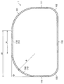
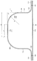
図4は、図1に示す断面形状の変形例を示す。湾曲部102,103の曲率半径は互いに同じであり、湾曲部100の曲率半径は、湾曲部103の曲率半径より大きい。湾曲部100,101の曲率半径は互いに同じであるため、例えば湾曲部100を基準湾曲部10としてよい。基準湾曲部10の長手方向両端にそれぞれ連続する平面部110,111のうち長いほうの平面部110を基準平面部11とする。基準湾曲部10の曲率半径Rが式(1)を満足し、基準平面部11の長さb1が式(2)を満足するように設定すれば、図1に示す例と同様の作用効果が得られる。例えば、曲率半径Rは15mm以上であってよく、長さb1は10mm以上であってよい。
[Modification 1-1]
FIG. 4 shows a modified example of the cross-sectional shape shown in FIG. The radius of curvature of the
[変形例1−2]
図5は、図1に示す断面形状の変形例を示す。湾曲部102,103の曲率半径は互いに同じであり、湾曲部100の曲率半径は、湾曲部103の曲率半径より大きい。湾曲部100,101の曲率半径は互いに同じであるため、例えば湾曲部100を基準湾曲部10としてよい。基準湾曲部10の長手方向両端にそれぞれ連続する平面部110,113のうち長いほうの平面部110を基準平面部11とする。基準湾曲部10の曲率半径Rが式(1)を満足し、基準平面部11の長さb1が式(2)を満足するように設定すれば、図1に示す例と同様の作用効果が得られる。例えば、曲率半径Rは15mm以上であってよく、長さb1は10mm以上であってよい。
[Modification 1-2]
FIG. 5 shows a modified example of the cross-sectional shape shown in FIG. The radius of curvature of the
[変形例1−3]
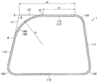
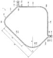
図6は、図1に示す断面形状の変形例を示す。湾曲部100,101,102,103のうち、曲率半径が最大である湾曲部100を基準湾曲部10とする。基準湾曲部10の長手方向両端にそれぞれ連続する平面部110,113のうち長いほうの平面部110を基準平面部11とする。基準湾曲部10を間に挟んで第1直線L1と第2直線L2がなす角度θは、100°〜110°である。基準湾曲部10の曲率半径Rが式(1)を満足し、基準平面部11の長さb1が式(2)を満足するように設定すれば、図1に示す例と同様の作用効果が得られる。例えば、曲率半径Rは15mm以上であってよく、長さb1は10mm以上であってよい。
[Modification 1-3]
FIG. 6 shows a modified example of the cross-sectional shape shown in FIG. Of the
<第2の実施形態>
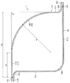
車体部材1は、所定の形状に成形された複数の部材が溶接等により1つに接合することで形成されてもよい。図7は、このように形成された車体部材1の軸直角方向断面の一例を示す。この断面は、閉断面であってよい。車体部材1は、第1部材1Aと第2部材1Bとが溶接により接合することで、筒状に形成されている。第1部材1Aの軸直角方向断面は、2つの湾曲部100,101と、3つの平面部110,111,112とを有する。平面部112は接合用のフランジとして機能する。湾曲部101は、平面部112を平面部111に対して折り曲げ形成するときに通常生じうる比較的小さな湾曲部であってよい。第2部材1Bの軸直角方向断面は、2つの湾曲部102,103と、3つの平面部113,114,115とを有する。平面部115は接合用のフランジとして機能する。湾曲部103は、平面部115を平面部114に対して折り曲げ形成するときに通常生じうる比較的小さな湾曲部であってよい。第1部材1Aの平面部112が、溶接部131を介して、第2部材1Bの平面部113の長手方向端部に接合している。第1部材1Aの平面部110の長手方向端部が、溶接部132を介して、第2部材1Bの平面部115に接合している。湾曲部101,103は、車体部材1の内側に凸である。湾曲部100,101,102,103のうち、曲率半径が最大である湾曲部100を基準湾曲部10とする。基準湾曲部10の長手方向両端にそれぞれ連続する平面部110,111のうち長いほうの平面部110を基準平面部11とする。
<Second embodiment>
The
基準湾曲部10の曲率半径Rが上記式(1)を満足し、基準平面部11の長さb1が上記式(2)を満足するように設定すれば、第1の実施形態と同様の作用効果が得られる。例えば、曲率半径Rは15mm以上であってよく、長さb1は10mm以上であってよい。なお、基準平面部11としての平面部110の長さb1は、湾曲部100との接続部位から、溶接部132までの長さであり、溶接部132よりも先端側における自由端の長さは含まれない。
If the radius of curvature R of the reference curved
[変形例2−1]
図8は、図7に示す断面形状の変形例を示す。第1部材1Aの軸直角方向断面は、4つの湾曲部100,101,102,103と、5つの平面部110,111,112,114,115とを有する。平面部112,114は接合用のフランジとして機能する。湾曲部101,102は、平面部112,114をそれぞれ平面部111,115に対して折り曲げ形成するときに通常生じうる比較的小さな湾曲部であってよい。第2部材1Bは平板状であり、その軸直角方向断面は、1つの平面部113を有する。第1部材1Aの平面部112,114が、それぞれ溶接部131,132を介して、第2部材1Bの平面部113の長手方向端部に接合している。湾曲部101,102の曲率半径は互いに同じであり、湾曲部100の曲率半径は、湾曲部101の曲率半径より大きい。湾曲部100,103の曲率半径は互いに同じであるため、例えば湾曲部100を基準湾曲部10としてよい。基準湾曲部10の長手方向両端にそれぞれ連続する平面部110,111のうち長いほうの平面部110を基準平面部11とする。基準湾曲部10の曲率半径Rが式(1)を満足し、基準平面部11の長さb1が式(2)を満足するように設定すれば、図7に示す例と同様の作用効果が得られる。例えば、曲率半径Rは15mm以上であってよく、長さb1は10mm以上であってよい。
[Modification 2-1]
FIG. 8 shows a modified example of the cross-sectional shape shown in FIG. The cross section of the
[変形例2−2]
図9は、図7に示す断面形状の変形例を示す。第1部材1Aの軸直角方向断面は、4つの湾曲部100,101,102,106と、5つの平面部110,111,112,117,118とを有する。平面部112,117は接合用のフランジとして機能する。湾曲部102,106は、平面部112,117をそれぞれ平面部111,118に対して折り曲げ形成するときに通常生じうる比較的小さな湾曲部であってよい。第2部材1Bの軸直角方向断面は、3つの湾曲部103,104,105と、4つの平面部113,114,115,116とを有する。平面部113,116は接合用のフランジとして機能する。湾曲部103,105は、平面部113,116をそれぞれ平面部114,115に対して折り曲げ形成するときに通常生じうる比較的小さな湾曲部であってよい。第1部材1Aの平面部112,117が、それぞれ溶接部131,132を介して、第2部材1Bの平面部113,116に接合している。湾曲部100〜106のうち、曲率半径が最大である湾曲部100を基準湾曲部10とする。基準湾曲部10の長手方向両端にそれぞれ連続する平面部110,118のうち長いほうの平面部110を基準平面部11とする。基準湾曲部10の曲率半径Rが式(1)を満足し、基準平面部11の長さb1が式(2)を満足するように設定すれば、図7に示す例と同様の作用効果が得られる。例えば、曲率半径Rは15mm以上であってよく、長さb1は10mm以上であってよい。
[Modification 2-2]
FIG. 9 shows a modified example of the cross-sectional shape shown in FIG. The cross section of the
[変形例2−3]
図10は、図7に示す断面形状の変形例を示す。第1部材1Aの軸直角方向断面は、4つの湾曲部100,101,106,107と、5つの平面部110,111,112,118,119とを有する。平面部112,118は接合用のフランジとして機能する。湾曲部101,106は、平面部112,118をそれぞれ平面部111,119に対して折り曲げ形成するときに通常生じうる比較的小さな湾曲部であってよい。第2部材1Bの軸直角方向断面は、4つの湾曲部102,103,104,105と、5つの平面部113,114,115,116,117とを有する。平面部113,117は接合用のフランジとして機能する。湾曲部102,105は、平面部113,117をそれぞれ平面部114,116に対して折り曲げ形成するときに通常生じうる比較的小さな湾曲部であってよい。第1部材1Aの平面部112,118が、それぞれ溶接部131,132を介して、第2部材1Bの平面部113,117に接合している。湾曲部100〜107のうち、曲率半径が最大である湾曲部100を基準湾曲部10とする。基準湾曲部10の長手方向両端にそれぞれ連続する平面部110,111のうち長いほうの平面部110を基準平面部11とする。基準湾曲部10の曲率半径Rが式(1)を満足し、基準平面部11の長さb1が式(2)を満足するように設定すれば、図7に示す例と同様の作用効果が得られる。例えば、曲率半径Rは15mm以上であってよく、長さb1は10mm以上であってよい。
[Modification 2-3]
FIG. 10 shows a modified example of the cross-sectional shape shown in FIG. The cross section of the
[変形例2−4]
図11は、図7に示す断面形状の変形例を示す。車体部材1の軸直角方向断面は、略ハット形状の閉断面である。第1部材1Aの軸直角方向断面は、8つの湾曲部100,101,102,103,104,105,106,107と、7つの平面部110,111,112,113,115,116,117とを有する。平面部113,115は接合用のフランジとして機能する。湾曲部104,105は、平面部113,115をそれぞれ平面部112,116に対して折り曲げ形成するときに通常生じうる比較的小さな湾曲部であってよい。湾曲部100と湾曲部107は、平面部を介さずに、互いに連続する。湾曲部101と湾曲部102は、平面部を介さずに、互いに連続する。湾曲部100,101,102,107および平面部110により、平面部111,117から車体部材1の内側に向かって突出する凹部12が形成されている。凹部12は、車体部材1の長手方向(軸方向)に沿って延びる溝状である。第2部材1Bは平板状であり、その軸直角方向断面は、1つの平面部114を有する。第1部材1Aの平面部113,115が、それぞれ溶接部131,132を介して、第2部材1Bの平面部113の長手方向端部に接合している。湾曲部100,101は、車体部材1の内側に凸である。湾曲部100,101の曲率半径は、他の湾曲部102〜107の曲率半径より大きい。湾曲部100,101の曲率半径は互いに同じであるため、例えば湾曲部100を基準湾曲部10としてよい。基準湾曲部10の長手方向両端のうち一端のみに平面部が連続するため、この平面部110を基準平面部11とする。
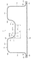
[Modification 2-4]
FIG. 11 shows a modified example of the cross-sectional shape shown in FIG. The cross section of the
基準湾曲部10の曲率半径Rが式(1)を満足し、基準平面部11の長さb1が式(2)を満足するように設定すれば、図7に示す例と同様の作用効果が得られる。例えば、曲率半径Rは15mm以上であってよく、長さb1は10mm以上であってよい。本変形例では、第1部材1Aの平面部が3つに分割されているため、軸直角方向断面における各平面部110,111,117の長さが短くなり、上記式(2)の右辺で規定される上限値以下となりやすくなる。これにより、各平面部で弾性座屈が抑制される。また、第1部材1Aが凹部12を有することにより、曲げモーメントに対する車体部材1の耐力が向上し、さらに衝撃吸収特性も向上する。
If the radius of curvature R of the reference curved
[車体部材の適用例]
以上、本発明の好適な実施の形態について詳細に説明した。ここから、図12を参照して実施形態に係る車体部材1の適用例について説明する。図12は、車体部材1が適用される一例としての自動車骨格2を示す図である。車体部材1は、キャビン骨格または衝撃吸収骨格として自動車骨格2を構成し得る。
[Application example of vehicle body member]
The preferred embodiment of the present invention has been described in detail above. From here, an application example of the
キャビン骨格としての車体部材1の適用例は、ルーフセンタリンフォース201、ルーフサイドレール203、Bピラー207、サイドシル209、トンネル211、Aピラーロア213、Aピラーアッパー215、キックリーンフォース227、フロアクロスメンバ229、アンダーリーンフォース231、フロントヘッダ233等が挙げられる。また、衝撃吸収骨格としての車体部材1の適用例は、リアサイドメンバー205、エプロンアッパメンバ217、バンパリーンフォース219、クラッシュボックス221、フロントサイドメンバー223等が挙げられる。上記の他、自動車のドアの内部に設けられた補強材としてのドアインパクトビーム等に車体部材1を適用してもよい。要は、軸方向に圧縮力が作用しうる部位であれば、本実施形態の車体部材1を適用可能である。
Examples of application of the
このように車体部材1がキャビン骨格または衝撃吸収骨格として使用される場合、車体部材1は高い軸方向圧縮耐力を有するので、衝突時の変形を低減できる。また、変形能も向上して、骨格内部を保護することができる。
When the
以上、添付図面を参照しながら本発明の好適な実施形態について詳細に説明したが、本発明はかかる例に限定されない。本発明の属する技術の分野における通常の知識を有する者であれば、特許請求の範囲に記載された技術的思想の範疇内において、各種の変更例または修正例に想到し得ることは明らかであり、これらについても、当然に本発明の技術的範囲に属するものと了解される。 Although the preferred embodiments of the present invention have been described in detail with reference to the accompanying drawings, the present invention is not limited to such examples. It is clear that a person having ordinary knowledge in the field of technology to which the present invention belongs can come up with various modifications or modifications within the scope of the technical ideas described in the claims. , These are also naturally understood to belong to the technical scope of the present invention.
例えば、湾曲部は、車体部材の軸直角方向断面に少なくとも1つあればよく、湾曲部が1つであってもよい。また、平面部は、車体部材の軸直角方向断面に少なくとも1つあればよく、平面部が1つであってもよい。車体部材の軸直角方向断面は、閉断面でなくてもよく、開断面であってもよい。例えば、図8〜11に示す変形例において、第2部材1Bが省略され、第1部材1Aのみが車体部材として用いられてもよい。これらの場合も、軸直角方向断面において基準平面部の長手方向両端が単純支持されているとみなせるため、上記式(1)または式(2)を満足する場合に上記作用効果が得られる。
For example, there may be at least one curved portion in the cross section in the direction perpendicular to the axis of the vehicle body member, and there may be one curved portion. Further, at least one flat surface portion may be required in the cross section in the direction perpendicular to the axis of the vehicle body member, and one flat surface portion may be provided. The cross section of the vehicle body member in the direction perpendicular to the axis may not be a closed cross section but may be an open cross section. For example, in the modified examples shown in FIGS. 8 to 11, the
1 車体部材
10 基準湾曲部
11 基準平面部
L1 第1直線
L2 第2直線
1
Claims (6)
板厚が1.6mm以下である鋼板により形成され、
軸直角方向断面の形状が、
外側または内側に凸の少なくとも1つの湾曲部と、少なくとも1つの平面部とを有し、
曲率半径が最大である1つの前記湾曲部を基準湾曲部とし、
前記基準湾曲部の長手方向両端のうち、一端のみに前記平面部が連続する場合は当該平面部、両端に前記平面部が連続する場合は当該平面部のうち長いほうの前記平面部を、それぞれ基準平面部とし、
前記基準湾曲部の長手方向両端のうち前記基準平面部が連続しないほうの端から前記基準湾曲部の接線方向に延びる直線を第1直線とし、
前記基準平面部の延長線を第2直線とし、
前記第1直線と前記第2直線の交点と、前記基準平面部の長手方向両端のうち前記基準湾曲部に連続しないほうの端と、の間の長さをb0とし、
前記基準平面部の長さをb1とし、
前記基準湾曲部の曲率半径をRとするとき、
以下の式(1)および式(2)を満足する、
車体部材。
ただし、前記基準平面部を形成する部分の鋼板の、板厚をt、ヤング率をE、ポアソン比をν、降伏応力をσyとする。
Formed from a steel plate with a plate thickness of 1.6 mm or less,
The shape of the cross section in the direction perpendicular to the axis
It has at least one curved portion that is convex outward or inward and at least one flat portion.
The one said curved portion having the maximum radius of curvature is used as a reference curved portion.
Of both ends in the longitudinal direction of the reference curved portion, when the flat surface portion is continuous only at one end, the flat surface portion is used, and when the flat surface portion is continuous at both ends, the longer flat surface portion is used. As a reference plane part
The straight line extending in the tangential direction of the reference curved portion from the end of the longitudinal end of the reference curved portion where the reference plane portion is not continuous is defined as the first straight line.
The extension line of the reference plane portion is set as the second straight line.
The length between the intersection of the first straight line and the second straight line and the end of the reference plane portion in the longitudinal direction that is not continuous with the reference curved portion is set to b0.
Let the length of the reference plane portion be b1.
When the radius of curvature of the reference curved portion is R,
Satisfy the following equations (1) and (2),
Body member.
However, the thickness of the steel plate forming the reference plane portion is t, Young's modulus is E, Poisson's ratio is ν, and the yield stress is σ y .
The vehicle body member according to any one of claims 1 to 5, wherein the cross section in the direction perpendicular to the axis is a closed cross section.
Priority Applications (2)
| Application Number | Priority Date | Filing Date | Title |
|---|---|---|---|
| JP2019053191A JP7288183B2 (en) | 2019-03-20 | 2019-03-20 | body parts |
| JP2023043604A JP7738592B2 (en) | 2019-03-20 | 2023-03-17 | Body parts |
Applications Claiming Priority (1)
| Application Number | Priority Date | Filing Date | Title |
|---|---|---|---|
| JP2019053191A JP7288183B2 (en) | 2019-03-20 | 2019-03-20 | body parts |
Related Child Applications (1)
| Application Number | Title | Priority Date | Filing Date |
|---|---|---|---|
| JP2023043604A Division JP7738592B2 (en) | 2019-03-20 | 2023-03-17 | Body parts |
Publications (2)
| Publication Number | Publication Date |
|---|---|
| JP2020152257A true JP2020152257A (en) | 2020-09-24 |
| JP7288183B2 JP7288183B2 (en) | 2023-06-07 |
Family
ID=72557465
Family Applications (2)
| Application Number | Title | Priority Date | Filing Date |
|---|---|---|---|
| JP2019053191A Active JP7288183B2 (en) | 2019-03-20 | 2019-03-20 | body parts |
| JP2023043604A Active JP7738592B2 (en) | 2019-03-20 | 2023-03-17 | Body parts |
Family Applications After (1)
| Application Number | Title | Priority Date | Filing Date |
|---|---|---|---|
| JP2023043604A Active JP7738592B2 (en) | 2019-03-20 | 2023-03-17 | Body parts |
Country Status (1)
| Country | Link |
|---|---|
| JP (2) | JP7288183B2 (en) |
Cited By (5)
| Publication number | Priority date | Publication date | Assignee | Title |
|---|---|---|---|---|
| JPWO2021166988A1 (en) * | 2020-02-18 | 2021-08-26 | ||
| JP2023174333A (en) * | 2022-05-27 | 2023-12-07 | Jfeスチール株式会社 | Energy absorption structural member and deformation control method therefor |
| WO2025079378A1 (en) * | 2023-10-12 | 2025-04-17 | 日本製鉄株式会社 | Automotive structural member |
| WO2025205621A1 (en) * | 2024-03-29 | 2025-10-02 | 日本製鉄株式会社 | Skeleton member, vehicle body, and method for manufacturing skeleton member |
| WO2025243608A1 (en) * | 2024-05-21 | 2025-11-27 | 住友重機械工業株式会社 | Pillar support member assembly, pipe member support member assembly, vehicle structure, pillar, and pipe member |
Families Citing this family (2)
| Publication number | Priority date | Publication date | Assignee | Title |
|---|---|---|---|---|
| WO2025143053A1 (en) * | 2023-12-27 | 2025-07-03 | 株式会社クボタ | Cabin and deformed pipe used for cabin |
| WO2026028437A1 (en) * | 2024-08-02 | 2026-02-05 | 日産自動車株式会社 | Vehicle structure |
Citations (4)
| Publication number | Priority date | Publication date | Assignee | Title |
|---|---|---|---|---|
| JP2002248941A (en) * | 2001-02-26 | 2002-09-03 | Nippon Steel Corp | Automotive structural members |
| JP2004315858A (en) * | 2003-04-14 | 2004-11-11 | Nippon Steel Corp | Steel members with excellent impact characteristics |
| JP2012236525A (en) * | 2011-05-12 | 2012-12-06 | Mazda Motor Corp | Vehicular frame structure |
| WO2016060255A1 (en) * | 2014-10-17 | 2016-04-21 | 新日鐵住金株式会社 | Impact absorption member |
Family Cites Families (3)
| Publication number | Priority date | Publication date | Assignee | Title |
|---|---|---|---|---|
| JP5103959B2 (en) * | 2007-03-13 | 2012-12-19 | トヨタ自動車株式会社 | Front pillar structure for vehicles |
| MX2018015402A (en) * | 2016-06-16 | 2019-04-22 | Nippon Steel & Sumitomo Metal Corp | Drawn body for automobile structural member, method for manufacturing drawn body for automobile structural member, and apparatus for manufacturing drawn body for automobile structural member. |
| KR102379059B1 (en) * | 2017-04-10 | 2022-03-28 | 닛폰세이테츠 가부시키가이샤 | Press-molded article and structural member for automobiles that uses same |
-
2019
- 2019-03-20 JP JP2019053191A patent/JP7288183B2/en active Active
-
2023
- 2023-03-17 JP JP2023043604A patent/JP7738592B2/en active Active
Patent Citations (4)
| Publication number | Priority date | Publication date | Assignee | Title |
|---|---|---|---|---|
| JP2002248941A (en) * | 2001-02-26 | 2002-09-03 | Nippon Steel Corp | Automotive structural members |
| JP2004315858A (en) * | 2003-04-14 | 2004-11-11 | Nippon Steel Corp | Steel members with excellent impact characteristics |
| JP2012236525A (en) * | 2011-05-12 | 2012-12-06 | Mazda Motor Corp | Vehicular frame structure |
| WO2016060255A1 (en) * | 2014-10-17 | 2016-04-21 | 新日鐵住金株式会社 | Impact absorption member |
Cited By (11)
| Publication number | Priority date | Publication date | Assignee | Title |
|---|---|---|---|---|
| JPWO2021166988A1 (en) * | 2020-02-18 | 2021-08-26 | ||
| WO2021166988A1 (en) * | 2020-02-18 | 2021-08-26 | 日本製鉄株式会社 | Vehicle body structural member and method for designing vehicle body structural member |
| JP7243913B2 (en) | 2020-02-18 | 2023-03-22 | 日本製鉄株式会社 | Car body structural member and method for designing car body structural member |
| JP2023174333A (en) * | 2022-05-27 | 2023-12-07 | Jfeスチール株式会社 | Energy absorption structural member and deformation control method therefor |
| JP7548273B2 (en) | 2022-05-27 | 2024-09-10 | Jfeスチール株式会社 | Energy absorbing structural member and deformation control method thereof |
| WO2025079378A1 (en) * | 2023-10-12 | 2025-04-17 | 日本製鉄株式会社 | Automotive structural member |
| JPWO2025079378A1 (en) * | 2023-10-12 | 2025-04-17 | ||
| JP7842371B2 (en) | 2023-10-12 | 2026-04-08 | 日本製鉄株式会社 | Automotive structural components |
| WO2025205621A1 (en) * | 2024-03-29 | 2025-10-02 | 日本製鉄株式会社 | Skeleton member, vehicle body, and method for manufacturing skeleton member |
| JPWO2025205621A1 (en) * | 2024-03-29 | 2025-10-02 | ||
| WO2025243608A1 (en) * | 2024-05-21 | 2025-11-27 | 住友重機械工業株式会社 | Pillar support member assembly, pipe member support member assembly, vehicle structure, pillar, and pipe member |
Also Published As
| Publication number | Publication date |
|---|---|
| JP2023075317A (en) | 2023-05-30 |
| JP7288183B2 (en) | 2023-06-07 |
| JP7738592B2 (en) | 2025-09-12 |
Similar Documents
| Publication | Publication Date | Title |
|---|---|---|
| JP2020152257A (en) | Body parts | |
| US10183321B2 (en) | Tubular back beam assembly for vehicle and method of manufacturing the same | |
| US11279408B2 (en) | Hollow member | |
| CN102791532B (en) | Motor Vehicle Parts | |
| CN109496183B (en) | Exterior panel for automobile | |
| KR102019219B1 (en) | Vehicle rear structure | |
| US11884332B2 (en) | Automobile hood | |
| JP5686586B2 (en) | Reinforcement structure in automobile body frame | |
| JP6488758B2 (en) | Shock absorbing member | |
| JP7243913B2 (en) | Car body structural member and method for designing car body structural member | |
| US11267517B2 (en) | Member and vehicle frame | |
| JP6566173B1 (en) | Front pillar outer | |
| JP7264597B2 (en) | Vehicle structural members and vehicles | |
| JP2024541325A (en) | Vehicle side sill | |
| WO2019130420A1 (en) | Impact-absorbing member | |
| JP7842340B2 (en) | Structural members | |
| JP7385121B2 (en) | Design method for vehicle body structural components | |
| JP6183475B2 (en) | Automobile frame parts and front pillar lowers including the same | |
| JP6838432B2 (en) | Impact resistant parts of automobiles | |
| CN111976435B (en) | Anti-collision beam of vehicle door made of aluminum alloy | |
| CN110475706B (en) | Impact absorbing member and side member for automobile | |
| WO2021010395A1 (en) | Front pillar outer | |
| JP2009280145A (en) | Vehicular impact absorber and vehicular bumper device |
Legal Events
| Date | Code | Title | Description |
|---|---|---|---|
| RD03 | Notification of appointment of power of attorney |
Free format text: JAPANESE INTERMEDIATE CODE: A7423 Effective date: 20190419 |
|
| RD04 | Notification of resignation of power of attorney |
Free format text: JAPANESE INTERMEDIATE CODE: A7424 Effective date: 20190422 |
|
| RD04 | Notification of resignation of power of attorney |
Free format text: JAPANESE INTERMEDIATE CODE: A7424 Effective date: 20190426 |
|
| A621 | Written request for application examination |
Free format text: JAPANESE INTERMEDIATE CODE: A621 Effective date: 20211104 |
|
| A977 | Report on retrieval |
Free format text: JAPANESE INTERMEDIATE CODE: A971007 Effective date: 20221017 |
|
| A131 | Notification of reasons for refusal |
Free format text: JAPANESE INTERMEDIATE CODE: A131 Effective date: 20221018 |
|
| A521 | Request for written amendment filed |
Free format text: JAPANESE INTERMEDIATE CODE: A523 Effective date: 20221216 |
|
| A131 | Notification of reasons for refusal |
Free format text: JAPANESE INTERMEDIATE CODE: A131 Effective date: 20230124 |
|
| A521 | Request for written amendment filed |
Free format text: JAPANESE INTERMEDIATE CODE: A523 Effective date: 20230317 |
|
| TRDD | Decision of grant or rejection written | ||
| A01 | Written decision to grant a patent or to grant a registration (utility model) |
Free format text: JAPANESE INTERMEDIATE CODE: A01 Effective date: 20230425 |
|
| A61 | First payment of annual fees (during grant procedure) |
Free format text: JAPANESE INTERMEDIATE CODE: A61 Effective date: 20230508 |
|
| R151 | Written notification of patent or utility model registration |
Ref document number: 7288183 Country of ref document: JP Free format text: JAPANESE INTERMEDIATE CODE: R151 |