JP2020171027A - Sending terminal - Google Patents
Sending terminal Download PDFInfo
- Publication number
- JP2020171027A JP2020171027A JP2020102287A JP2020102287A JP2020171027A JP 2020171027 A JP2020171027 A JP 2020171027A JP 2020102287 A JP2020102287 A JP 2020102287A JP 2020102287 A JP2020102287 A JP 2020102287A JP 2020171027 A JP2020171027 A JP 2020171027A
- Authority
- JP
- Japan
- Prior art keywords
- control period
- side link
- control
- control information
- transmission
- Prior art date
- Legal status (The legal status is an assumption and is not a legal conclusion. Google has not performed a legal analysis and makes no representation as to the accuracy of the status listed.)
- Granted
Links
Images





Classifications
-
- H—ELECTRICITY
- H04—ELECTRIC COMMUNICATION TECHNIQUE
- H04W—WIRELESS COMMUNICATION NETWORKS
- H04W72/00—Local resource management
- H04W72/04—Wireless resource allocation
-
- H—ELECTRICITY
- H04—ELECTRIC COMMUNICATION TECHNIQUE
- H04W—WIRELESS COMMUNICATION NETWORKS
- H04W28/00—Network traffic management; Network resource management
- H04W28/02—Traffic management, e.g. flow control or congestion control
- H04W28/06—Optimizing the usage of the radio link, e.g. header compression, information sizing, discarding information
-
- G—PHYSICS
- G01—MEASURING; TESTING
- G01N—INVESTIGATING OR ANALYSING MATERIALS BY DETERMINING THEIR CHEMICAL OR PHYSICAL PROPERTIES
- G01N33/00—Investigating or analysing materials by specific methods not covered by groups G01N1/00 - G01N31/00
- G01N33/15—Medicinal preparations ; Physical properties thereof, e.g. dissolubility
-
- H—ELECTRICITY
- H04—ELECTRIC COMMUNICATION TECHNIQUE
- H04W—WIRELESS COMMUNICATION NETWORKS
- H04W72/00—Local resource management
- H04W72/04—Wireless resource allocation
- H04W72/044—Wireless resource allocation based on the type of the allocated resource
- H04W72/0446—Resources in time domain, e.g. slots or frames
-
- H—ELECTRICITY
- H04—ELECTRIC COMMUNICATION TECHNIQUE
- H04W—WIRELESS COMMUNICATION NETWORKS
- H04W72/00—Local resource management
- H04W72/20—Control channels or signalling for resource management
-
- H—ELECTRICITY
- H04—ELECTRIC COMMUNICATION TECHNIQUE
- H04W—WIRELESS COMMUNICATION NETWORKS
- H04W72/00—Local resource management
- H04W72/50—Allocation or scheduling criteria for wireless resources
- H04W72/51—Allocation or scheduling criteria for wireless resources based on terminal or device properties
-
- H—ELECTRICITY
- H04—ELECTRIC COMMUNICATION TECHNIQUE
- H04W—WIRELESS COMMUNICATION NETWORKS
- H04W76/00—Connection management
- H04W76/10—Connection setup
- H04W76/14—Direct-mode setup
-
- H—ELECTRICITY
- H04—ELECTRIC COMMUNICATION TECHNIQUE
- H04W—WIRELESS COMMUNICATION NETWORKS
- H04W8/00—Network data management
- H04W8/005—Discovery of network devices, e.g. terminals
-
- H—ELECTRICITY
- H04—ELECTRIC COMMUNICATION TECHNIQUE
- H04W—WIRELESS COMMUNICATION NETWORKS
- H04W92/00—Interfaces specially adapted for wireless communication networks
- H04W92/16—Interfaces between hierarchically similar devices
- H04W92/18—Interfaces between hierarchically similar devices between terminal devices
-
- H—ELECTRICITY
- H04—ELECTRIC COMMUNICATION TECHNIQUE
- H04W—WIRELESS COMMUNICATION NETWORKS
- H04W88/00—Devices specially adapted for wireless communication networks, e.g. terminals, base stations or access point devices
- H04W88/02—Terminal devices
- H04W88/06—Terminal devices adapted for operation in multiple networks or having at least two operational modes, e.g. multi-mode terminals
Landscapes
- Engineering & Computer Science (AREA)
- Computer Networks & Wireless Communication (AREA)
- Signal Processing (AREA)
- Life Sciences & Earth Sciences (AREA)
- Health & Medical Sciences (AREA)
- Chemical & Material Sciences (AREA)
- Databases & Information Systems (AREA)
- Medicinal Chemistry (AREA)
- Analytical Chemistry (AREA)
- Pharmacology & Pharmacy (AREA)
- Biophysics (AREA)
- Food Science & Technology (AREA)
- Bioinformatics & Cheminformatics (AREA)
- Physics & Mathematics (AREA)
- Molecular Biology (AREA)
- Biochemistry (AREA)
- General Health & Medical Sciences (AREA)
- General Physics & Mathematics (AREA)
- Immunology (AREA)
- Pathology (AREA)
- Mobile Radio Communication Systems (AREA)
Abstract
【課題】周期的なD2D制御期間内の制御用の無線リソース領域で送信され且つD2D送信リソースを指定するスケジューリング割当情報の受信失敗を低減することに寄与する。【解決手段】送信端末(1A)は、第1のD2D制御期間(501)内の第1のサブフレーム・プール(511)内の1又は複数のサブフレームにおいて第1のD2D制御情報(522、523)を送信するとともに、当該第1のD2D制御期間(501)内の第2のサブフレーム・プール(512)内の1又は複数のサブフレームにおいて第1のD2D制御情報(522、523)に従ってデータ送信(531−534)を行う。当該第1のD2D制御情報(522、523)は、当該第1のD2D制御期間(501)より後の少なくとも1つのD2D制御期間(502、503)において当該第1のD2D制御情報(522、523)が有効であるか否かを示す第2の情報要素を含む。【選択図】図5PROBLEM TO BE SOLVED: To reduce reception failure of scheduling allocation information transmitted in a radio resource area for control within a periodic D2D control period and designating a D2D transmission resource. A transmitting terminal (1A) has first D2D control information (522,) in one or more subframes in a first subframe pool (511) within a first D2D control period (501). 523) is transmitted and according to the first D2D control information (522, 523) in one or more subframes in the second subframe pool (512) within the first D2D control period (501). Data transmission (531-534) is performed. The first D2D control information (522, 523) is the first D2D control information (522, 523) in at least one D2D control period (502, 503) after the first D2D control period (501). ) Includes a second information element indicating whether or not is valid. [Selection diagram] Fig. 5
Description
本開示は、端末間直接通信(device-to-device(D2D)通信)に関し、特にD2D通信のための無線リソースの割り当てに関する。 The present disclosure relates to direct terminal-to-terminal communication (device-to-device (D2D) communication), and particularly to allocation of wireless resources for D2D communication.
無線端末が基地局等のインフラストラクチャ・ネットワークを介さずに他の無線端末と直接的に通信する形態は、device-to-device(D2D)通信と呼ばれる。D2D通信は、直接通信(Direct Communication)および直接ディスカバリ(Direct Discovery)の少なくとも一方を含む。いくつかの実装において、D2D通信をサポートする複数の無線端末は、自律的に又はネットワークの指示に従ってD2D通信グループを形成し、当該D2D通信グループ内の他の無線端末と通信を行う。 A form in which a wireless terminal directly communicates with another wireless terminal without going through an infrastructure network such as a base station is called device-to-device (D2D) communication. D2D communication includes at least one of direct communication and direct discovery. In some implementations, multiple wireless terminals that support D2D communication form a D2D communication group autonomously or according to network instructions and communicate with other wireless terminals within the D2D communication group.
3GPP Release 12に規定されたProximity-based services(ProSe)は、D2D通信の一例である(例えば、非特許文献1を参照)。ProSe直接ディスカバリは、ProSeを実行可能な無線端末(ProSe-enabled User Equipment(UE))が他のProSe-enabled UEを、これら2つのUEが有する無線通信技術(例えば、Evolved Universal Terrestrial Radio Access (E-UTRA) technology)の能力だけを用いてディスカバリする手順により行われる。ProSe直接ディスカバリは、3つ以上のProSe-enabled UEsにより行われてもよい。 Proximity-based services (ProSe) specified in 3GPP Release 12 is an example of D2D communication (see, for example, Non-Patent Document 1). In ProSe direct discovery, a wireless terminal (ProSe-enabled User Equipment (UE)) capable of executing ProSe has another ProSe-enabled UE, and the wireless communication technology (for example, Evolved Universal Terrestrial Radio Access (E)) of these two UEs. -It is done by the procedure of discovery using only the ability of UTRA) technology). ProSe direct discovery may be performed by three or more ProSe-enabled UEs.
ProSe直接通信は、ProSe直接ディスカバリの手順の後に、直接通信レンジ内に存在する2以上のProSe-enabled UEsの間の通信パスの確立を可能にする。言い換えると、ProSe直接通信は、ProSe-enabled UEが、基地局(eNodeB(eNB))を含む公衆地上移動通信ネットワーク(Public Land Mobile Network (PLMN))を経由せずに、他のProSe-enabled UEと直接的に通信することを可能にする。ProSe直接通信は、基地局(eNB)にアクセスする場合と同様の無線通信技術(E-UTRA technology)を用いて行われてもよいし、Wireless Local Area Network (WLAN)の無線技術(つまり、IEEE 802.11 radio technology)を用いて行われてもよい。 ProSe direct communication allows the establishment of a communication path between two or more ProSe-enabled UEs existing within the direct communication range after the procedure of ProSe direct discovery. In other words, ProSe direct communication allows the ProSe-enabled UE to go through another ProSe-enabled UE without going through the Public Land Mobile Network (PLMN), which includes the base station (eNodeB (eNB)). Allows you to communicate directly with. ProSe direct communication may be performed using the same wireless communication technology (E-UTRA technology) as when accessing a base station (eNB), or wireless local area network (WLAN) wireless technology (that is, IEEE). It may be done using 802.11 radio technology).
3GPP Release 12では、直接通信または直接ディスカバリに用いられる無線端末間の無線リンクは、サイドリンク(Sidelink)と呼ばれる(例えば、非特許文献2のセクション14を参照)。サイドリンク送信は、アップリンク及びダウンリンクのために定義されたLong Term Evolution(LTE)フレーム構造と同じフレーム構造を使用し、周波数および時間ドメインにおいてアップリンク・リソースのサブセットを使用する。無線端末(UE)は、アップリンクと同様のシングルキャリア周波数分割多重(Single Carrier FDMA(Frequency Division Multiple Access)、SC-FDMA)を使用してサイドリンク送信を行う。 In 3GPP Release 12, the radio link between radio terminals used for direct communication or direct discovery is called a side link (see, eg, Section 14 of Non-Patent Document 2). Sidelink transmission uses the same frame structure as the Long Term Evolution (LTE) frame structure defined for uplinks and downlinks, and uses a subset of uplink resources in the frequency and time domains. The wireless terminal (UE) performs side link transmission using single carrier frequency division multiplexing (Single Carrier FDMA (Frequency Division Multiple Access), SC-FDMA) similar to uplink.
3GPP Release 12 ProSeでは、サイドリンク送信のための無線リソースのUEへの割り当ては、無線アクセスネットワーク(e.g., Evolved Universal Terrestrial Radio Access Network(E-UTRAN))によって行われる。ProSe functionによってサイドリンク通信を許可されたUEは、無線アクセスネットワークノード(e.g., eNB(eNB))によって割り当てられた無線リソースを使用してProSe直接ディスカバリ又はProSe直接通信を行う。 In 3GPP Release 12 ProSe, radio resources for sidelink transmission are allocated to the UE by the radio access network (e.g., Evolved Universal Terrestrial Radio Access Network (E-UTRAN)). UEs authorized for side-link communication by the ProSe function perform ProSe direct discovery or ProSe direct communication using the radio resources allocated by the radio access network node (e.g., eNB (eNB)).
ProSe直接通信に関しては、2つのリソース割り当てモード、つまりscheduled resource allocation 及び autonomous resource selectionが規定されているscheduled resource allocation 及び autonomous resource selection は、それぞれ“sidelink transmission mode 1”及び“sidelink transmission mode 2”と呼ばれる(非特許文献2のセクション14を参照)。
For ProSe direct communication, two resource allocation modes, namely scheduled resource allocation and autonomous resource selection, which specify scheduled resource allocation and autonomous resource selection, are called "
ProSe直接通信のscheduled resource allocationでは、UEがサイドリンク送信を希望する場合、当該UEがサイドリンク送信のための無線リソース割り当てをeNBに要求し、eNBがサイドリンク・コントロール及びデータのためのリソースを当該UEに割り当てる。具体的には、UEは、アップリンク(UL)データ送信リソース(Uplink Shared Channel(UL-SCH)リソース)を要求するためにスケジューリング・リクエストをeNB に送信し、アップリンクグラント(UL grant)で割り当てられたULデータ送信リソースにおいてSidelink Buffer Status Report(Sidelink BSR)をeNBに送信する。eNBは、Sidelink BSRに基づいてUEに割り当てるサイドリンク送信リソースを決定し、サイドリンク・グラント(SL grant)をUEに送信する。 In the scheduled resource allocation of ProSe direct communication, if the UE wishes to send sidelinks, the UE requests the eNB to allocate radio resources for sidelink transmission, and the eNB provides resources for sidelink control and data. Assign to the UE. Specifically, the UE sends a scheduling request to the eNB to request an Uplink (UL) data transmission resource (Uplink Shared Channel (UL-SCH) resource) and allocates it with an uplink grant (UL grant). Send the Sidelink Buffer Status Report (Sidelink BSR) to the eNB in the UL data transmission resource. The eNB determines the sidelink transmission resource to be allocated to the UE based on the Sidelink BSR and transmits the sidelink grant (SL grant) to the UE.
SL grantは、Downlink Control Information(DCI) format 5として定義されている。SL grant(DCI format 5)は、Resource for PSCCH、Resource block assignment and hopping allocation、及びtime resource pattern indexなどのコンテンツを含む。Resource for PSCCHは、サイドリンク制御チャネル(i.e., Physical Sidelink Control Channel(PSCCH))用の無線リソースを示す。Resource block assignment and hopping allocationは、サイドリンクでのデータ送信用のサイドリンク・データチャネル(i.e., Physical Sidelink Shared Channel(PSSCH))を送信するための周波数リソース、つまりサブキャリア(リソースブロック)のセット、を決定するために使用される。Time resource pattern indexは、PSSCHを送信するための時間リソース、つまりサブフレームのセット、を決定するために使用される。なお、厳密に述べると、リソースブロックは、LTE及びLTE-Advancedの時間−周波数リソースを意味し、時間ドメインにおいて連続する複数個のOFDM(又はSC-FDMA)シンボルと周波数ドメインにおいて連続する複数個のサブキャリアによって規定されるリソース単位である。Normal cyclic prefixの場合、1リソースブロックは、時間ドメインにおいて連続する12OFDM(又はSC-FDMA)シンボルを含み、周波数ドメインにおいて12サブキャリアを含む。すなわち、Resource block assignment and hopping allocationおよびTime resource pattern indexは、PSSCHを送信するためのリソースブロックを指定する。UE(つまり、サイドリンク送信端末)は、SL grantに従ってPSCCHリソースおよびPSSCHリソースを決める。 SL grants are defined as Downlink Control Information (DCI) format 5. SL grant (DCI format 5) includes content such as Resource for PSCCH, Resource block assignment and hopping allocation, and time resource pattern index. Resource for PSCCH indicates a radio resource for a sidelink control channel (i.e., Physical Sidelink Control Channel (PSCCH)). Resource block assignment and hopping allocation is a set of frequency resources, or subcarriers (resource blocks), for transmitting a sidelink data channel (ie, Physical Sidelink Shared Channel (PSSCH)) for data transmission on the sidelink. Used to determine. The Time resource pattern index is used to determine the time resource for sending PSSCH, the set of subframes. Strictly speaking, a resource block means LTE and LTE-Advanced time-frequency resources, and a plurality of consecutive OFDM (or SC-FDMA) symbols in the time domain and a plurality of consecutive OFDM (or SC-FDMA) symbols in the frequency domain. A resource unit defined by a subcarrier. In the case of Normal cyclic prefix, one resource block contains 12 consecutive OFDM (or SC-FDMA) symbols in the time domain and 12 subcarriers in the frequency domain. That is, Resource block assignment and hopping allocation and Time resource pattern index specify the resource block for sending PSSCH. The UE (that is, the sidelink transmitting terminal) determines the PSCCH resource and the PSSCH resource according to the SL grant.
一方、ProSe直接通信のautonomous resource selectionでは、UEは、eNBによって設定されたリソースプールの中から、サイドリンク・コントロール(PSCCH)及びデータ(PSSCH)のためのリソースを自律的に選択する。eNBは、System Information Block(SIB)18において、autonomous resource selectionに使用するためのリソースプールをUEに割り当ててもよい。なお、eNBは、Radio Resource Control (RRC)_CONNECTEDのUEに対して、個別(dedicated)RRCシグナリングで、autonomous resource selectionに使用するためのリソースプールを割り当ててもよい。このリソースプールは、UEがRRC_IDLEであるときにも利用可能であってもよい。 On the other hand, in the autonomous resource selection of ProSe direct communication, the UE autonomously selects resources for side link control (PSCCH) and data (PSSCH) from the resource pool set by eNB. The eNB may allocate a resource pool to the UE for use in autonomous resource selection in System Information Block (SIB) 18. Note that the eNB may allocate a resource pool for use in autonomous resource selection by dedicated RRC signaling to the UE of Radio Resource Control (RRC) _CONNECTED. This resource pool may also be available when the UE is RRC_IDLE.
サイドリンクでの直接送信を行う場合、送信側のUE(D2D transmitting UE)(以下、送信端末とする)は、サイドリンク制御チャネル(i.e., PSCCH)用の無線リソース領域(resource pool)を使って、スケジューリング割当情報(Scheduling Assignment)の送信を行う。スケジューリング割当情報は、Sidelink Control Information (SCI) format 0とも呼ばれる。スケジューリング割当情報は、resource block assignment and hopping allocation、time resource pattern index、及び Modulation and Coding Scheme(MCS)などのコンテンツを含む。上述したscheduled resource allocation の場合、Scheduling Assignment(SCI format 0)が示す Resource block assignment and hopping allocation及びtime resource pattern indexは、eNBから受信したSL grant(DCI format 5)が示すResource block assignment and hopping allocation及びtime resource pattern indexに従う。 When performing direct transmission via a side link, the transmitting UE (D2D transmitting UE) (hereinafter referred to as the transmitting terminal) uses the radio resource area (resource pool) for the side link control channel (ie, PSCCH). , Send scheduling assignment information (Scheduling Assignment). Scheduling allocation information is also known as Sidelink Control Information (SCI) format 0. Scheduling allocation information includes content such as resource block assignment and hopping allocation, time resource pattern index, and Modulation and Coding Scheme (MCS). In the case of the scheduled resource allocation described above, the Resource block allocation and hopping allocation and time resource pattern index indicated by the Scheduling Assignment (SCI format 0) are the Resource block allocation and hopping allocation indicated by the SL grant (DCI format 5) received from the eNB. Follow the time resource pattern index.
送信端末は、スケジューリング割当情報に従った無線リソースを使って、PSSCHにおいてデータを送信する。受信側のUE(D2D receiving UE)(以下、受信端末とする)は、送信端末からのスケジューリング割当情報をPSCCHにおいて受信し、そのスケジューリング割当情報に従ってPSSCHにおいてデータを受信する。なお、ここで送信端末との用語は、無線端末の送信動作に着目した表現であって、送信専用の無線端末を意味するものではない。同様に、受信端末との用語は、無線端末の受信動作に着目した表現であり、受信専用の端末を意味するものではない。すなわち、送信端末は受信動作を行うことも可能であり、受信端末は送信動作を行うことも可能である。 The transmitting terminal transmits data in PSSCH using radio resources according to the scheduling allocation information. The receiving UE (D2D receiving UE) (hereinafter referred to as a receiving terminal) receives the scheduling allocation information from the transmitting terminal on the PSCCH, and receives the data on the PSSCH according to the scheduling allocation information. The term "transmission terminal" here is an expression focusing on the transmission operation of the wireless terminal, and does not mean a wireless terminal dedicated to transmission. Similarly, the term receiving terminal is an expression focusing on the receiving operation of the wireless terminal, and does not mean a receiving-only terminal. That is, the transmitting terminal can also perform a receiving operation, and the receiving terminal can also perform a transmitting operation.
以下では、サイドリンク制御期間(sidelink control period)、PSCCHのためのリソースプール、及びPSSCHのためのリソースプールについて説明する。これらは、PSCCHを送信するための無線リソース(i.e., subframes及びresource blocks)及びPSSCHを送信するための無線リソースを決定するために必要である。既に説明したように、PSCCHは、スケジューリング割当情報などのサイドリンク制御情報(Sidelink Control Information (SCI))の送信に使用されるサイドリンクの物理チャネルである。一方、PSSCHは、ユーザデータ送信(ダイレクト送信)のために使用されるサイドリンクの物理チャネルである。 The sidelink control period, the resource pool for PSCCH, and the resource pool for PSSCH will be described below. These are needed to determine the radio resources (i.e., subframes and resource blocks) for transmitting PSCCH and the radio resources for transmitting PSSCH. As described above, PSCCH is a sidelink physical channel used to transmit sidelink control information (SCI) such as scheduling allocation information. PSSCH, on the other hand, is a side-link physical channel used for user data transmission (direct transmission).
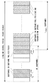
サイドリンク制御期間(sidelink control period)は、サイドリンクのためのスケジューリング周期である(図1を参照)。サイドリンク制御期間は、PSCCH periodとも呼ばれる。送信端末は、サイドリンク制御期間毎にスケジューリング割当情報(i.e., SCI format 0)を送信する。3GPP Release 12では、サイドリンク制御期間は、40ms, 60ms, 70ms, 80ms, 120ms, 140ms, 160ms, 240ms, 280ms, 又は320msである。言い換えると、サイドリンク制御期間は、40サブフレーム, 60サブフレーム, 70サブフレーム, 80サブフレーム, 120サブフレーム, 140サブフレーム, 160サブフレーム, 240サブフレーム, 280サブフレーム, 又は320サブフレームである。 The sidelink control period is a scheduling cycle for sidelinks (see FIG. 1). The side link control period is also called the PSCCH period. The transmitting terminal transmits scheduling allocation information (i.e., SCI format 0) for each side link control period. In 3GPP Release 12, the side link control period is 40ms, 60ms, 70ms, 80ms, 120ms, 140ms, 160ms, 240ms, 280ms, or 320ms. In other words, the sidelink control period is 40 subframes, 60 subframes, 70 subframes, 80 subframes, 120 subframes, 140 subframes, 160 subframes, 240 subframes, 280 subframes, or 320 subframes. is there.
したがって、送信端末は、サイドリンク制御期間毎に、つまり40 ms又はそれ以上の周期で、PSSCHリソースの割り当てを受信端末に通知する。ただし、PSSCHリソースの割り当てはtime resource pattern indexを用いて6、7又は8サブフレーム(6, 7, or 8 ms)単位で指定される。したがって、1つのサイドリンク制御期間の間は、6、7又は8サブフレーム周期で同じPSSCHリソースの割り当てが使用される。 Therefore, the transmitting terminal notifies the receiving terminal of the PSSCH resource allocation every side link control period, that is, at a cycle of 40 ms or more. However, PSSCH resource allocation is specified in units of 6, 7 or 8 subframes (6, 7, or 8 ms) using the time resource pattern index. Therefore, during one side link control period, the same PSSCH resource allocation is used in 6, 7 or 8 subframe cycles.
1つのサイドリンク制御期間において、送信端末は、PSCCHのためのリソースプール(サブフレームプール)に含まれるLPSCCH個のサブフレームのうち2つのサブフレームにおいてスケジューリング割当情報(i.e., SCI format 0)を2回送信する。これら2回の送信は、PSCCHのためのリソースプール(リソースブロックプール)に含まれるMPSCCH_RP RB個のリソースブロックのうち異なる2つのリソースブロックにおいて行われる。 In one side link control period, the transmitting terminal performs scheduling allocation information (ie, SCI format 0) in two subframes out of L PSCCH subframes included in the resource pool (subframe pool) for PSCCH. Send twice. These two transmissions are performed in two different resource blocks out of M PSCCH_RP RB resource blocks included in the resource pool (resource block pool) for PSCCH .
PSCCHのためのリソースプールは、ブロードキャスト(SIB 18)又は個別シグナリング(RRCシグナリング)でeNBによってUEに設定される。PSCCHのためのリソースプールは、サイドリンク制御期間内のLPSCCH個のサブフレーム及びMPSCCH_RP RB個の周波数ドメイン・リソースブロックから成る。 The resource pool for PSCCH is set in the UE by eNB by broadcast (SIB 18) or individual signaling (RRC signaling). The resource pool for PSCCH consists of L PSCCH subframes and M PSCCH_RP RB frequency domain resource blocks within the sidelink control period.
PSCCHのためのリソースプールの指定方法について図2及び図3を用いて説明する。PSCCHのためのリソースプールは、サブフレーム・プールとリソースブロック・プールから成る。図2は、PSCCHのためのサブフレーム・プールを示しており、図3は、PSCCHのためのリソースブロック・プールを示している。 The method of specifying the resource pool for PSCCH will be described with reference to FIGS. 2 and 3. The resource pool for PSCCH consists of a subframe pool and a resource block pool. FIG. 2 shows a subframe pool for PSCCH and FIG. 3 shows a resource block pool for PSCCH.
eNBは、PSCCHのためのサブフレーム・プールを特定するために、サイドリンク制御期間(PSCCH期間)の長さ(P)、並びにPSCCHのためのサブフレーム・ビットマップ及びその長さ(N’)を指定する。サブフレーム・ビットマップの長さ(N’)は、4、8、12、16、30、40又は42 bitsである。当該サブフレーム・ビットマップに対応するN’サブフレームは、図2に示すように、サイドリンク制御期間内の最初のN’サブフレームである。サブフレーム・ビットマップは、“0”にセットされたビットに対応するサブフレームがPSCCH送信に使用されないことを示し、“1”にセットされたビットに対応するサブフレームがPSCCH送信に使用できることを示す。したがって、1つのサイドリンク制御期間内のPSCCHリソースプールに含まれるサブフレーム数(LPSCCH)は、サブフレーム・ビットマップで値1が指定されている数に等しい。PSCCHリソースプール(つまり、サブフレーム・プール)に含まれるサブフレームは、以下のように表すことができる:
一方、図3に示すように、eNBは、PSCCHのためのリソースブロック・プールを特定するために、開始(start)Physical Resource Block(PRB)のインデックス(S1)、終了(end)PRBのインデックス(S2)、及びPRB数(M)を指定する。リソースブロック・プールは、PRBインデックスqが開始インデッククス(S1)以上であり且つS1+Mより小さい(S1 <= q < S1+M)M個のPRBsと、PRBインデックスqがS2-Mより大きく且つ終了インデッククス(S2)以下である(S2-M < q <= S2)M個のPRBsを含む(つまり、合計2M個のPRBs)。すなわち、eNBは、各々がM個のPRBsを含む2つのPRBクラスターをPSCCHのためのリソースブロック・プールに含めることができる。 On the other hand, as shown in FIG. 3, the eNB indexes the start (start) Physical Resource Block (PRB) (S1) and the index (end) PRB in order to identify the resource block pool for PSCCH. Specify S2) and the number of PRBs (M). The resource block pool has M PRBs with a PRB index q greater than or equal to the starting index (S1) and less than S1 + M (S1 <= q <S1 + M), and a PRB index q greater than S2-M. It also contains M PRBs (S2-M <q <= S2) less than or equal to the end index (S2) (that is, a total of 2M PRBs). That is, the eNB can include two PRB clusters, each containing M PRBs, in the resource block pool for PSCCH.
次に、PSSCHのためのリソースプールの指定方法について説明する。Scheduled resource allocation(sidelink transmission mode 1)の場合、eNBは、PSSCHのためのサブフレーム・プールをSIB 18又は個別シグナリング(RRCシグナリング)で指定する。PSCCHリソース設定に関連付けられサイドリンク制御期間(PSCCH期間)は、PSSCHリソース設定にもさらに関連付けられる。UEは、サブフレーム・プールから成るPSSCHリソースプールを以下のように決定する。すなわち、図2に示されるように、サイドリンク制御期間(PSCCH期間)内において、lPSCCH PSCCH-1 + 1と同じかこれより大きいサブフレーム・インデックスを持つ各サブフレームは、PSSCHのためのサブフレーム・プールに属する。 Next, the method of specifying the resource pool for PSSCH will be described. For Scheduled resource allocation (sidelink transmission mode 1), the eNB specifies the subframe pool for PSSCH with SIB 18 or individual signaling (RRC signaling). The side link control period (PSCCH period) associated with the PSCCH resource setting is also associated with the PSSCH resource setting. The UE determines the PSSCH resource pool, which consists of subframe pools, as follows: That is, as shown in FIG. 2, within the side link control period (PSCCH period), each subframe with a subframe index equal to or greater than l PSCCH PSCCH-1 + 1 is a subframe for PSSCH. Belongs to the frame pool.
一方、autonomous resource selection(sidelink transmission mode 2)の場合、eNBは、PSSCHのためのサブフレーム・プール及びリソースブロック・プールをSIB 18又は個別シグナリング(RRCシグナリング)で指定する。eNBは、サブフレーム・プールを指定するために、オフセット(O2)、並びにサブフレーム・ビットマップ及びその長さ(NB)を指定する。 On the other hand, in the case of autonomous resource selection (sidelink transmission mode 2), eNB specifies the subframe pool and resource block pool for PSSCH by SIB 18 or individual signaling (RRC signaling). eNB in order to specify the subframe pool, Offset (O 2), and specifying the sub-frame bitmap and its length (N B).
オフセット(O2)は、サイドリンク制御期間(PSCCH期間)の先頭サブフレームのサブフレーム・インデックスjbeginからのオフセットを示す。ここでは、PSCCH期間内においてjbegin + O2と同じかこれより大きいサブフレーム・インデックスを持つ各サブフレームの総数をN’とする。 The offset (O 2 ) indicates the offset from the subframe index j begin of the first subframe of the side link control period (PSCCH period). Here, N'is the total number of each subframe having the same or larger subframe index as j begin + O 2 within the PSCCH period.
サブフレーム・ビットマップの長さ(NB)は、4、8、12、16、30、40又は42 bitsである。サブフレーム・ビットマップは、“0”にセットされたビットに対応するサブフレームがPSSCH送信に使用されないことを示し、“1”にセットされたビットに対応するサブフレームがPSSCH送信に使用できることを示す。なお、通常の場合、サブフレーム・ビットマップの長さ(NB)は、PSCCH期間内においてjbegin + O2と同じかこれより大きいサブフレーム・インデックスを持つサブフレームの総数(N’)より小さい。したがって、UEは、ビットマップb0, b1, b2, ..., bN’-1を以下の数式に従って決定する:
Autonomous resource selection(sidelink transmission mode 2)の場合のPSSCHのためのリソースブロック・プールは、PSCCHのためのリソースブロック・プールと同様に指定される。すなわち、eNBは、PSSCHのためのリソースブロック・プールを特定するために、開始(start)Physical Resource Block(PRB)のインデックス(S1)、終了(end)PRBのインデックス(S2)、及びPRB数(M)をPSSCHリソース設定において指定する。 The resource block pool for PSSCH in the case of Autonomous resource selection (sidelink transmission mode 2) is specified in the same way as the resource block pool for PSCCH. That is, the eNB has the index (S1) of the start Physical Resource Block (PRB), the index (S2) of the end PRB, and the number of PRBs (S2) to identify the resource block pool for PSSCH. Specify M) in the PSSCH resource settings.
上述したように、3GPP Release 12のサイドリンク送信は、周波数および時間ドメインにおいてアップリンク・リソースのサブセットを使用する。したがって、UEは、サイドリンク送信中のサブフレームにおいて、他のUEから送信されたサイドリンク信号を受信することができない。なぜなら、UE自身が送信している信号が大電力の干渉となって当該UEに受信されてしまうためである。 As mentioned above, 3GPP Release 12 sidelink transmissions use a subset of uplink resources in the frequency and time domains. Therefore, the UE cannot receive the side link signal transmitted from another UE in the subframe during the side link transmission. This is because the signal transmitted by the UE itself becomes a high-power interference and is received by the UE.
したがって、UEは、スケジューリング割当情報(i.e., SCI format 0)をPSCCH上で送信しているサブフレームでは、他のUEから送信されたスケジューリング割当情報(SCI format 0)を受信できない。UEは、あるサイドリンク制御期間(PSCCH期間)内のスケジューリング割当情報の受信に失敗した場合、当該スケジューリング割当情報に関連付けられた当該サイドリンク制御期間内でのデータ受信(PSSCH受信)もまた失敗する。なお、スケジューリング割当情報が送信されるPSCCH用の無線リソース領域(PSCCHのためのサブフレーム・プール)に含まれるサブフレーム数は、データ送信(PSSCH送信)用の無線リソース領域(PSSCHのためのサブフレーム・プール)に含まれるサブフレーム数に比べて少ないことに留意されるべきである。このため、UEがPSCCHでのスケジューリング割当情報(i.e., SCI format 0)の送信を行っているために、他のUEからのスケジューリング割当情報を受信できないという状況は発生しやすい。 Therefore, the UE cannot receive the scheduling allocation information (SCI format 0) transmitted from other UEs in the subframe in which the scheduling allocation information (i.e., SCI format 0) is transmitted on the PSCCH. If the UE fails to receive the scheduling allocation information within a certain side link control period (PSCCH period), the data reception (PSSCH reception) within the side link control period associated with the scheduling allocation information also fails. .. The number of subframes included in the radio resource area for PSCCH (subframe pool for PSCCH) to which scheduling allocation information is transmitted is the number of subframes for data transmission (PSSCH transmission) (subframe for PSSCH). It should be noted that the number of subframes contained in the frame pool) is small. Therefore, since the UE transmits the scheduling allocation information (i.e., SCI format 0) in PSCCH, the situation that the scheduling allocation information from other UEs cannot be received is likely to occur.
本明細書に開示される実施形態が達成しようとする目的の1つは、周期的なD2D制御期間(e.g., サイドリンク制御期間)内の制御用の無線リソース領域(e.g., PSCCHのためのリソースプール)で送信され且つD2D送信リソース(e.g., PSSCH送信のためのサブフレーム及びリソースブロック)を指定するスケジューリング割当情報(e.g., SCI format 0)の受信失敗を低減することに寄与する装置、方法、及びプログラムを提供することである。 One of the objectives to be achieved by the embodiments disclosed herein is a resource area for control (eg, resources for PSCCH) within a periodic D2D control period (eg, sidelink control period). A device, method, or device that contributes to reducing reception failures of scheduling allocation information (eg, SCI format 0) that is transmitted in a pool) and specifies D2D transmission resources (eg, subframes and resource blocks for PSSCH transmission). And to provide a program.
第1の態様では、送信端末は、少なくとも1つの無線トランシーバ、及び少なくとも1つのプロセッサを含む。前記少なくとも1つのプロセッサは、前記少なくとも1つの無線トランシーバに結合され、周期的なdevice-to-device(D2D)制御期間に従って基地局を介さずに他の無線端末へのデータ送信を行うよう構成されている。各D2D制御期間は、D2D制御情報の送信のために使用可能な複数のサブフレームから成る第1のサブフレーム・プールと、前記D2D制御情報に従う前記データ送信のために使用可能な複数のサブフレームから成る第2のサブフレーム・プールを含む。前記少なくとも1つのプロセッサは、第1のD2D制御期間内の前記第1のサブフレーム・プール内の1又は複数のサブフレームにおいて第1のD2D制御情報を送信するとともに、前記第1のD2D制御期間内の前記第2のサブフレーム・プール内の1又は複数のサブフレームにおいて前記第1のD2D制御情報に従って前記データ送信を行うよう構成されている、前記第1のD2D制御情報は、前記第1のD2D制御期間内の前記第2のサブフレーム・プール内の1又は複数のサブフレームを特定するための第1の情報要素を含む。前記第1のD2D制御情報は、さらに、前記第1のD2D制御期間より後の少なくとも1つのD2D制御期間において前記第1のD2D制御情報が有効であるか否かを示す第2の情報要素を含む。 In the first aspect, the transmitting terminal comprises at least one radio transceiver and at least one processor. The at least one processor is coupled to the at least one radio transceiver and is configured to transmit data to another radio terminal without going through a base station according to a periodic device-to-device (D2D) control period. ing. Each D2D control period includes a first subframe pool consisting of a plurality of subframes available for transmission of D2D control information and a plurality of subframes available for transmission of the data according to the D2D control information. Includes a second subframe pool consisting of. The at least one processor transmits the first D2D control information in one or more subframes in the first subframe pool within the first D2D control period, and the first D2D control period. The first D2D control information is configured to transmit the data according to the first D2D control information in one or more subframes in the second subframe pool. Includes a first information element for identifying one or more subframes in the second subframe pool within the D2D control period of. The first D2D control information further includes a second information element indicating whether or not the first D2D control information is valid in at least one D2D control period after the first D2D control period. Including.
第2の態様では、送信端末における方法は、周期的なdevice-to-device(D2D)制御期間に従って基地局を介さずに受信端末へのデータ送信を行うことを含む。各D2D制御期間は、D2D制御情報の送信のために使用可能な複数のサブフレームから成る第1のサブフレーム・プールと、前記D2D制御情報に従う前記データ送信のために使用可能な複数のサブフレームから成る第2のサブフレーム・プールを含む。前記D2D送信を前記行うことは、第1のD2D制御期間内の前記第1のサブフレーム・プール内の1又は複数のサブフレームにおいて第1のD2D制御情報を送信するとともに、前記第1のD2D制御期間内の前記第2のサブフレーム・プール内の1又は複数のサブフレームにおいて前記第1のD2D制御情報に従って前記データ送信を行うことを含む。前記第1のD2D制御情報は、前記第1のD2D制御期間内の前記第2のサブフレーム・プール内の1又は複数のサブフレームを特定するための第1の情報要素を含む。前記第1のD2D制御情報は、さらに、前記第1のD2D制御期間より後の少なくとも1つのD2D制御期間において前記第1のD2D制御情報が有効であるか否かを示す第2の情報要素を含む。 In the second aspect, the method at the transmitting terminal comprises transmitting data to the receiving terminal according to a periodic device-to-device (D2D) control period without going through a base station. Each D2D control period includes a first subframe pool consisting of a plurality of subframes available for transmission of D2D control information and a plurality of subframes available for transmission of the data according to the D2D control information. Includes a second subframe pool consisting of. Performing the D2D transmission transmits the first D2D control information in one or more subframes in the first subframe pool within the first D2D control period, and also transmits the first D2D. This includes transmitting the data according to the first D2D control information in one or more subframes in the second subframe pool within the control period. The first D2D control information includes a first information element for identifying one or more subframes in the second subframe pool within the first D2D control period. The first D2D control information further includes a second information element indicating whether or not the first D2D control information is valid in at least one D2D control period after the first D2D control period. Including.
第3の態様では、受信端末は、少なくとも1つの無線トランシーバ、及び少なくとも1つのプロセッサを含む。前記少なくとも1つのプロセッサは、前記少なくとも1つの無線トランシーバに結合され、周期的なdevice-to-device(D2D)制御期間に従って基地局を介さずに送信端末からのデータ受信を行うよう構成されている。各D2D制御期間は、D2D制御情報の送信のために使用可能な複数のサブフレームから成る第1のサブフレーム・プールと、前記D2D制御情報に従う前記データ受信のために使用可能な複数のサブフレームから成る第2のサブフレーム・プールを含む。前記少なくとも1つのプロセッサは、第1のD2D制御期間内の前記第1のサブフレーム・プール内の1又は複数のサブフレームにおいて第1のD2D制御情報を受信するとともに、前記第1のD2D制御期間内の前記第2のサブフレーム・プール内の1又は複数のサブフレームにおいて前記第1のD2D制御情報に従って前記データ受信を行うよう構成されている。前記第1のD2D制御情報は、前記第1のD2D制御期間内の前記第2のサブフレーム・プール内の1又は複数のサブフレームを特定するための第1の情報要素を含む。前記第1のD2D制御情報は、さらに、前記第1のD2D制御期間より後の少なくとも1つのD2D制御期間において前記第1のD2D制御情報が有効であるか否かを示す第2の情報要素を含む。 In a third aspect, the receiving terminal comprises at least one radio transceiver and at least one processor. The at least one processor is coupled to the at least one radio transceiver and is configured to receive data from a transmitting terminal according to a periodic device-to-device (D2D) control period without going through a base station. .. Each D2D control period includes a first subframe pool consisting of a plurality of subframes available for transmission of D2D control information and a plurality of subframes available for receiving the data according to the D2D control information. Includes a second subframe pool consisting of. The at least one processor receives the first D2D control information in one or more subframes in the first subframe pool within the first D2D control period, and the first D2D control period. The data is received in one or a plurality of subframes in the second subframe pool according to the first D2D control information. The first D2D control information includes a first information element for identifying one or more subframes in the second subframe pool within the first D2D control period. The first D2D control information further includes a second information element indicating whether or not the first D2D control information is valid in at least one D2D control period after the first D2D control period. Including.
第4の態様では、受信端末における方法は、周期的なdevice-to-device(D2D)制御期間に従って基地局を介さずに送信端末からのデータ受信を行うことを含む。各D2D制御期間は、D2D制御情報の送信のために使用可能な複数のサブフレームから成る第1のサブフレーム・プールと、前記D2D制御情報に従う前記データ受信のために使用可能な複数のサブフレームから成る第2のサブフレーム・プールを含む。前記データ受信を前記行うことは、第1のD2D制御期間内の前記第1のサブフレーム・プール内の1又は複数のサブフレームにおいて第1のD2D制御情報を受信するとともに、前記第1のD2D制御期間内の前記第2のサブフレーム・プール内の1又は複数のサブフレームにおいて前記第1のD2D制御情報に従って前記データ受信を行うことを含む。前記第1のD2D制御情報は、前記第1のD2D制御期間内の前記第2のサブフレーム・プール内の1又は複数のサブフレームを特定するための第1の情報要素を含む。前記第1のD2D制御情報は、さらに、前記第1のD2D制御期間より後の少なくとも1つのD2D制御期間において前記第1のD2D制御情報が有効であるか否かを示す第2の情報要素を含む。 In a fourth aspect, the method at the receiving terminal comprises receiving data from the transmitting terminal according to a periodic device-to-device (D2D) control period without going through a base station. Each D2D control period includes a first subframe pool consisting of a plurality of subframes available for transmission of D2D control information and a plurality of subframes available for receiving the data according to the D2D control information. Includes a second subframe pool consisting of. Performing the data reception receives the first D2D control information in one or more subframes in the first subframe pool within the first D2D control period, and also receives the first D2D. This includes receiving the data according to the first D2D control information in one or more subframes in the second subframe pool within the control period. The first D2D control information includes a first information element for identifying one or more subframes in the second subframe pool within the first D2D control period. The first D2D control information further includes a second information element indicating whether or not the first D2D control information is valid in at least one D2D control period after the first D2D control period. Including.
第5の態様では、基地局は、セル内の複数の無線端末と通信するよう構成された無線トランシーバ、及び少なくとも1つのプロセッサを含む。前記少なくとも1つのプロセッサは、周期的なdevice-to-device(D2D)制御期間に従う第1の無線端末から第2の無線端末への前記基地局を介さないデータ送信を制御するよう構成されている。 各D2D制御期間は、D2D制御情報の送信のために使用可能な複数のサブフレームから成る第1のサブフレーム・プールと、前記D2D制御情報に従う前記データ送信のために使用可能な複数のサブフレームから成る第2のサブフレーム・プールを含む。前記少なくとも1つのプロセッサは、第1のD2D制御期間内での前記D2D制御情報の送信及び前記データ送信のための無線リソース割り当てを示すとともに、前記第1のD2D制御期間より後の少なくとも1つのD2D制御期間においても前記無線リソース割り当てが有効であることを示すD2Dグラントメッセージを前記第1の無線端末に送信するよう構成されている。 In a fifth aspect, the base station includes a radio transceiver configured to communicate with multiple radio terminals in the cell, and at least one processor. The at least one processor is configured to control data transmission from a first radio terminal to a second radio terminal without the base station according to a periodic device-to-device (D2D) control period. .. Each D2D control period includes a first subframe pool consisting of a plurality of subframes available for transmission of D2D control information and a plurality of subframes available for transmission of the data according to the D2D control information. Includes a second subframe pool consisting of. The at least one processor exhibits radio resource allocation for transmission of the D2D control information and data transmission within the first D2D control period, and at least one D2D after the first D2D control period. It is configured to transmit a D2D grant message indicating that the radio resource allocation is valid even during the control period to the first radio terminal.
第6の態様では、基地局における方法は、周期的なdevice-to-device(D2D)制御期間に従う第1の無線端末から第2の無線端末への前記基地局を介さないデータ送信を制御することを含む。各D2D制御期間は、D2D制御情報の送信のために使用可能な複数のサブフレームから成る第1のサブフレーム・プールと、前記D2D制御情報に従う前記データ送信のために使用可能な複数のサブフレームから成る第2のサブフレーム・プールを含む。前記制御することは、第1のD2D制御期間内での前記D2D制御情報の送信及び前記データ送信のための無線リソース割り当てを示すとともに、前記第1のD2D制御期間より後の少なくとも1つのD2D制御期間においても前記無線リソース割り当てが有効であることを示すD2Dグラントメッセージを前記第1の無線端末に送信することを含む。 In a sixth aspect, the method at the base station controls data transmission from the first radio terminal to the second radio terminal without the base station according to a periodic device-to-device (D2D) control period. Including that. Each D2D control period includes a first subframe pool consisting of a plurality of subframes available for transmission of D2D control information and a plurality of subframes available for transmission of the data according to the D2D control information. Includes a second subframe pool consisting of. The control indicates radio resource allocation for transmission of the D2D control information and data transmission within the first D2D control period, and at least one D2D control after the first D2D control period. This includes transmitting a D2D grant message indicating that the radio resource allocation is valid even during the period to the first radio terminal.
第7の態様では、プログラムは、コンピュータに読み込まれた場合に、上述の第2、第4、又は第6の態様に係る方法をコンピュータに行わせるための命令群(ソフトウェアコード)を含む。 In a seventh aspect, the program includes instructions (software code) for causing the computer to perform the method according to the second, fourth, or sixth aspect described above when loaded into the computer.
上述の態様によれば、周期的なD2D制御期間(e.g., サイドリンク制御期間)内の制御用の無線リソース領域(e.g., PSCCHのためのリソースプール)において送信され且つD2D送信リソース(e.g., PSSCH送信のためのサブフレーム及びリソースブロック)を指定するスケジューリング割当情報(e.g., SCI format 0)の受信失敗を低減することに寄与する装置、方法、及びプログラムを提供できる。 According to the above aspect, it is transmitted in the control radio resource area (eg, resource pool for PSCCH) within the periodic D2D control period (eg, sidelink control period) and the D2D transmit resource (eg, PSSCH). Devices, methods, and programs that contribute to reducing reception failures of scheduling allocation information (eg, SCI format 0) that specify subframes and resource blocks for transmission) can be provided.
以下では、具体的な実施形態について、図面を参照しながら詳細に説明する。各図面において、同一又は対応する要素には同一の符号が付されており、説明の明確化のため、必要に応じて重複説明は省略される。 Hereinafter, specific embodiments will be described in detail with reference to the drawings. In each drawing, the same or corresponding elements are designated by the same reference numerals, and duplicate explanations are omitted as necessary for the sake of clarity of explanation.
以下に示される複数の実施形態は、3GPP Release 12(LTE-Advanced)に規定されたProSeの改良を主な対象として説明される。しかしながら、これらの実施形態は、LTE-Advanced 及びその改良に限定されるものではなく、他のモバイル通信ネットワーク又はシステムでのD2D通信に適用されてもよい。 The plurality of embodiments shown below will be described mainly for the improvement of ProSe specified in 3GPP Release 12 (LTE-Advanced). However, these embodiments are not limited to LTE-Advanced and its improvements, and may be applied to D2D communication in other mobile communication networks or systems.
<第1の実施形態>
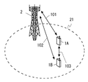
図4は、本実施形態を含むいくつかの実施形態に係る無線通信システムの構成例を示している。無線端末(UE)1A及び1Bの各々は、少なくとも1つの無線トランシーバを有し、基地局(eNB)2とのセルラー通信(101又は102)を行うとともに、端末間ダイレクトインタフェース(e.g., PC5インタフェース又はサイドリンク)103上でD2D通信を行うよう構成されている。当該D2D通信は、少なくとも直接通信(ProSe Direct Communication)を含み、直接ディスカバリ(e.g., ProSe Direct Discovery)をさらに含んでもよい。eNB2は、セル21を管理し、セルラー通信技術(e.g., Evolved Universal Terrestrial Radio Access (E-UTRA) technology)を用いて複数のUE1の各々とセルラー通信(101及び102)を行うことができる。なお、図5の例では、説明の簡略化のために複数のUE1A及び1Bが同じセル21内に位置している状況を示しているが、このような配置は一例に過ぎない。例えば、UE1Aは、異なるeNB2によって管理される互いに隣接する2つのセルの一方のセル内に位置し、UE1Bは他方のセル内に位置してもよい。あるいは、UE1A及びUE1Bのうち少なくとも一方は、1又は複数のeNB2によるカバレッジの外に位置してもよい。
<First Embodiment>
FIG. 4 shows a configuration example of a wireless communication system according to some embodiments including the present embodiment. Each of the wireless terminals (UE) 1A and 1B has at least one wireless transceiver, performs cellular communication (101 or 102) with the base station (eNB) 2, and has a direct interface between terminals (eg, PC5 interface or It is configured to perform D2D communication on the side link) 103. The D2D communication includes at least direct communication (ProSe Direct Communication), and may further include direct discovery (eg, ProSe Direct Discovery). The
続いて以下では、本実施形態に係るサイドリンクでのPSCCH及びPSSCHの送信について説明する。送信端末(e.g., UE1A)は、周期的なD2D制御期間(i.e., サイドリンク制御期間(PSCCH期間))に従ってeNB2を介さずに他の無線端末(受信端末(e.g., UE1B))へのデータ送信を行うよう構成されている。すでに説明したように、サイドリンク制御期間は、PSCCHのためのサブフレーム・プール(第1のサブフレーム・プール)及びPSSCHのためのサブフレーム・プール(第2のサブフレーム・プール)を含む。PSCCHのためのサブフレーム・プールは、スケジューリング割当情報(i.e., SCI format 0)を含むサイドリンク制御情報(SCI)の送信のために使用可能なLPSCCH個のサブフレームから成る。一方、PSSCHのためのサブフレーム・プールは、スケジューリング割当情報(i.e., SCI format 0)に従うデータ送信(PSSCH送信)のために使用可能なLPSSCH個のサブフレームから成る。 Subsequently, the transmission of PSCCH and PSSCH on the side link according to the present embodiment will be described below. The transmitting terminal (eg, UE1A) transmits data to another wireless terminal (receiving terminal (eg, UE1B)) according to a periodic D2D control period (ie, side link control period (PSCCH period)) without going through eNB2. Is configured to do. As described above, the side link control period includes a subframe pool for PSCCH (first subframe pool) and a subframe pool for PSSCH (second subframe pool). The subframe pool for PSCCH consists of L PSCCH subframes that can be used to send side link control information (SCI), including scheduling allocation information (ie, SCI format 0). On the other hand, the subframe pool for PSSCH consists of L PSSCH subframes that can be used for data transmission (PSSCH transmission) according to scheduling allocation information (ie, SCI format 0).
より具体的に述べると、送信端末(e.g., UE1A)は、第j番目のサイドリンク制御期間内のPSCCHサブフレーム・プール内の1又は複数のサブフレーム(e.g., 2つのサブフレーム)においてサイドリンク制御情報(D2D制御情報)を送信する。さらに、送信端末(e.g., UE1A)は、当該第j番目のサイドリンク制御期間内のPSSCHサブフレーム・プール内の1又は複数のサブフレームにおいて当該サイドリンク制御情報に従ってデータ送信(PSSCH送信)を行う。当該第j番目のサイドリンク制御期間において送信されるサイドリンク制御情報は、当該第j番目のサイドリンク制御期間内のPSSCHサブフレーム・プール内の1又は複数のサブフレームを特定するための第1の情報要素(i.e., スケジューリング割当情報(SCI format 0)を含む。これに加えて、当該第j番目のサイドリンク制御期間において送信されるサイドリンク制御情報は、当該サイドリンク制御情報によるデータ送信(PSSCH送信)のための無線リソース割り当てが第(j+1)番目以降の少なくとも1つのサイドリンク制御期間においても引き続き有効であるか否かを示す第2の情報要素を含む。 More specifically, the transmitting terminal (eg, UE1A) sidelinks in one or more subframes (eg, two subframes) in the PSCCH subframe pool within the jth sidelink control period. Send control information (D2D control information). Further, the transmitting terminal (eg, UE1A) transmits data (PSSCH transmission) according to the side link control information in one or more subframes in the PSSCH subframe pool within the jth side link control period. .. The side link control information transmitted in the jth side link control period is the first for identifying one or more subframes in the PSSCH subframe pool within the jth side link control period. (Ie, Scheduling allocation information (SCI format 0) is included. In addition, the side link control information transmitted in the jth side link control period is data transmission by the side link control information (ie, scheduling allocation information (SCI format 0)). It includes a second information element indicating whether the radio resource allocation for (PSSCH transmission) is still valid during at least one side link control period after the (j + 1) th.
送信端末(e.g., UE1A)は、第j番目のサイドリンク制御期間でのデータ送信のための無線リソース割り当てが引き続き有効とされる第(j+1)番目以降の少なくとも1つのサイドリンク制御期間において、新たなサイドリンク制御情報(スケジューリング割当情報(SCI format 0))を送信すること無くPSSCH上でのデータ送信を行うよう構成されてもよい。一方、受信端末(e.g., UE1B)は、第j番目のサイドリンク制御期間でのデータ送信のための無線リソース割り当てが第(j+1)番目以降の少なくとも1つのサイドリンク制御期間において引き続き有効とされる場合に、これらの第(j+1)番目以降のサイドリンク制御期間において新たなサイドリンク制御情報(スケジューリング割当情報)を受信すること無くPSSCH上でのデータ受信を行うよう構成されてもよい。 The transmitting terminal (eg, UE1A) is in at least one sidelink control period after the jth (j + 1) th period in which the radio resource allocation for data transmission in the jth sidelink control period is still valid. , It may be configured to transmit data on PSSCH without transmitting new side link control information (scheduling allocation information (SCI format 0)). On the other hand, the receiving terminal (eg, UE1B) is said that the radio resource allocation for data transmission in the jth side link control period is still valid in at least one side link control period after the (j + 1) th. Even if it is configured to receive data on PSSCH without receiving new side link control information (scheduling allocation information) in these (j + 1) th and subsequent side link control periods. Good.
これにより、第(j+1)番目以降の少なくとも1つのサイドリンク制御期間において当該送信端末が他のUE1からのサイドリンク制御情報の受信に失敗する確率を低減できる。また、本実施形態に係るPSCCH送信によれば、サイドリンク制御期間毎にサイドリンク制御情報(スケジューリング割当情報)を送信する場合に比べてPSCCH送信の発生回数を低減できる。したがって、互いに近接する複数のサイドリンク送信端末による複数のPSCCH送信が同一無線リソースで行われる衝突が発生する確率を低減できる。 As a result, it is possible to reduce the probability that the transmitting terminal fails to receive the side link control information from the other UE1 during at least one side link control period after the (j + 1) th. Further, according to the PSCCH transmission according to the present embodiment, the number of occurrences of PSCCH transmission can be reduced as compared with the case where the side link control information (scheduling allocation information) is transmitted for each side link control period. Therefore, it is possible to reduce the probability that a collision occurs in which a plurality of PSCCH transmissions by a plurality of side link transmitting terminals close to each other are performed by the same radio resource.
いくつかの実装において、当該第2の情報要素は、第(j+1)番目以降の少なくとも1つのサイドリンク制御期間(つまり、第j番目のサイドリンク制御期間でのデータ送信のための無線リソース割り当てが引き続き有効とされる少なくとも1つのサイドリンク制御期間)の長さを指定してもよい。例えば、当該第2の情報要素は、第j番目のサイドリンク制御期間において送信されるサイドリンク制御情報(スケジューリング割当情報(SCI format 0))が有効とされるサイドリンク制御期間の数を示してもよい。 In some implementations, the second information element is a radio resource for data transmission during at least one sidelink control period (ie, jthth sidelink control period) after the (j + 1) th. You may specify the length of at least one side link control period) for which the allocation remains valid. For example, the second information element indicates the number of side link control periods in which the side link control information (scheduling allocation information (SCI format 0)) transmitted in the jth side link control period is valid. May be good.
送信端末は、第j番目のサイドリンク制御期間でのデータ送信のための無線リソース割り当てが引き続き有効とされるサイドリンク制御期間の数(有効サイドリンク制御期間数と呼ぶ)を自律的に決定してもよい。これに代えて、送信端末は、無線リソース割り当ての有効サイドリンク制御期間数をeNB2によって設定されてもよい。例えば、scheduled resource allocation(sidelink transmission mode 1)の場合、eNB2は、サイドリンク・スケジューリング・グラント(DCI format 5)において無線リソース割り当ての有効サイドリンク制御期間数を送信端末に通知してもよい。Autonomous resource selection(sidelink transmission mode 2)の場合、eNB2は、SIB 18又はRRCシグナリングでのPSCCHリソース設定又はPSSCHリソース設定において、無線リソース割り当ての有効サイドリンク制御期間数を送信端末に通知してもよい。
The transmitting terminal autonomously determines the number of side link control periods (called the number of valid side link control periods) for which radio resource allocation for data transmission in the jth side link control period is still valid. You may. Alternatively, the transmitting terminal may set the number of valid side link control periods for radio resource allocation by eNB2. For example, in the case of scheduled resource allocation (sidelink transmission mode 1), the
例えば、送信端末は、データバッファに格納されたサイドリンク送信されるべきデータ量に応じて、無線リソース割り当ての有効サイドリンク制御期間数を決定してもよい。すなわち、送信端末は、未送信のデータを送信するために必要なPSSCHリソースに対応した有効サイドリンク制御期間数を決定してもよい。これにより、PSCCH上でのサイドリンク制御情報(スケジューリング割当情報(SCI format 0))の送信の回数を適切に減らすことができる。 For example, the transmitting terminal may determine the number of effective sidelink control periods for radio resource allocation according to the amount of data to be transmitted sidelinks stored in the data buffer. That is, the transmitting terminal may determine the number of effective side link control periods corresponding to the PSSCH resources required to transmit untransmitted data. As a result, the number of transmissions of side link control information (scheduling allocation information (SCI format 0)) on the PSCCH can be appropriately reduced.
例えば、送信端末は、アプリケーション(アプリケーションプログラム)が必要とする遅延要件に応じて、無線リソース割り当ての有効サイドリンク制御期間数を決定してもよい。ここで、遅延要件は、最大遅延、平均遅延、及び遅延保証に関する優先度、のうち少なくとも1つであってもよい。送信端末は、アプリケーションが厳しい遅延要件(つまり低遅延)を必要とする場合に、そうでない場合に比べて有効サイドリンク制御期間数を大きくしてもよい。これにより、長期間に渡ってサイドリンク制御情報の受信失敗とこれに付随するデータ送信の失敗が抑止されるため、アプリケーションが必要とする厳しい遅延要件(つまり低遅延)の達成に寄与できる。 For example, the transmitting terminal may determine the number of effective side link control periods for radio resource allocation according to the delay requirements required by the application (application program). Here, the delay requirement may be at least one of the maximum delay, the average delay, and the priority regarding the delay guarantee. The transmitting terminal may have a larger number of effective sidelink control periods when the application requires stringent delay requirements (ie, low latency) than it does not. As a result, the failure to receive the side link control information and the failure to transmit the data associated therewith are suppressed for a long period of time, which can contribute to the achievement of the strict delay requirement (that is, low delay) required by the application.
例えば、送信端末は、セル21内のサイドリンク送信の数またはサイドリンク送信端末の数に応じた有効サイドリンク制御期間数をeNB2によって設定されてもよい。例えば、eNB2は、セル21内のサイドリンク送信の数(サイドリンク送信端末の数)が大きいほど、有効サイドリンク制御期間数を大きくしてもよい。これにより、セル21内で行われるサイドリンク送信の数(サイドリンク送信端末の数)が大きい場合に、PSCCH送信の発生回数を減らすことができる。したがって、互いに近接する複数のサイドリンク送信端末による複数のPSCCH送信が同一無線リソースで行われる衝突が発生する確率を低減できる。
For example, the transmitting terminal may set the number of effective side link control periods according to the number of side link transmissions or the number of side link transmitting terminals in the
これに代えて、いくつかの実装において、当該第2の情報要素は、第j番目のサイドリンク制御期間でのデータ送信のための無線リソース割り当てが継続されるか否かを示してもよい。当該第2の情報要素は、無線リソース割り当ての継続の有無を示すフラグ情報であってもよい。例えば、当該第2の情報要素は、1ビットのフラグ情報であってもよい。フラグの値が“1”である場合に、第j番目のサイドリンク制御期間でのデータ送信のための無線リソース割り当てが第(j+1)番目以降のサイドリンク制御期間においても有効とされてもよい。一方、フラグの値が“0”である場合に、第j番目のサイドリンク制御期間でのデータ送信のための無線リソース割り当てが当該第j番目のサイドリンク制御期間においてのみ有効とされてもよい。 Alternatively, in some implementations, the second information element may indicate whether radio resource allocation for data transmission during the jth side link control period will continue. The second information element may be flag information indicating whether or not to continue radio resource allocation. For example, the second information element may be 1-bit flag information. When the value of the flag is "1", the radio resource allocation for data transmission in the jth side link control period is valid even in the (j + 1) th and subsequent side link control periods. May be good. On the other hand, when the value of the flag is "0", the radio resource allocation for data transmission in the jth side link control period may be valid only in the jth side link control period. ..
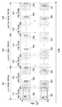
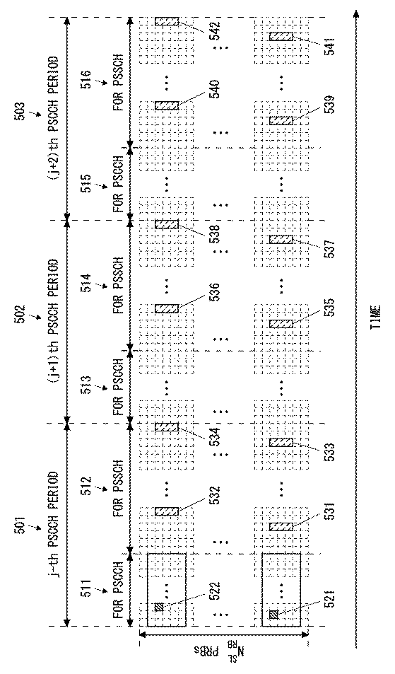
図5は、本実施形態に係るPSCCH及びPSSCHの送信の一例を示す図である。図5の例では、送信端末(e.g., UE1A)は、第j番目のサイドリンク制御期間(PSCCH期間)501内のPSCCHサブフレーム・プール511内の2つのサブフレームにおいてサイドリンク制御情報をPSCCH上で送信する(522及び523)。第j番目のサイドリンク制御期間501において送信されるサイドリンク制御情報522及び523は、スケジューリング割当情報(i.e., SCI format 0)を含むだけでなく、当該スケジューリング割当情報が第(j+1)番目のサイドリンク制御期間502及びそれ以降においても有効であることを示す。
FIG. 5 is a diagram showing an example of transmission of PSCCH and PSSCH according to the present embodiment. In the example of FIG. 5, the transmitting terminal (eg, UE1A) transmits side link control information on the PSCCH in two subframes in the
送信端末(e.g., UE1A)は、第j番目のサイドリンク制御期間501内のPSSCHサブフレーム・プール512内の複数のサブフレームにおいて、サイドリンク制御情報522及び523にしたがってデータ送信(PSSCH送信)531〜534を行う。さらに、送信端末(e.g., UE1A)は、第(j+1)番目のサイドリンク制御期間502内のPSCCHサブフレーム・プール513においてサイドリンク制御情報を送信せずに、サイドリンク制御期間502内のPSSCHサブフレーム・プール514においてデータ送信(PSSCH送信)535〜538を行う。データ送信(PSSCH送信)535〜538は、第j番目のサイドリンク制御期間501において送信されたサイドリンク制御情報522及び523に従う。これと同様に、送信端末(e.g., UE1A)は、第(j+2)番目のサイドリンク制御期間503内のPSCCHサブフレーム・プール515においてサイドリンク制御情報を送信せずに、サイドリンク制御期間503内のPSSCHサブフレーム・プール516においてデータ送信(PSSCH送信)539〜542を行う。データ送信(PSSCH送信)539〜542は、第j番目のサイドリンク制御期間501において送信されたサイドリンク制御情報522及び523に従う。
The transmitting terminal (eg, UE1A) transmits data (PSSCH transmission) 531 according to the side
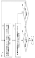
図6は、本実施形態に係る送信端末(e.g., UE1A)の動作の一例(処理600)を示すフローチャートである。ブロック601では、送信端末は、第j番目のサイドリンク制御期間(PSCCH期間)において、PSSCHリソース及び第(j+1)番目のサイドリンク制御期間(PSCCH期間)以降でのPSSCHリソース割り当ての有効性を示すサイドリンク制御情報(SCI)を受信端末(e.g., UE1B)に送信する。ブロック602では、送信端末は、第j番目のサイドリンク制御期間(PSCCH期間)において、第j番目のサイドリンク制御期間のサイドリンク制御情報に従ってPSSCH上でデータを送信する。
FIG. 6 is a flowchart showing an example (process 600) of the operation of the transmission terminal (e.g., UE1A) according to the present embodiment. In
ブロック603では、送信端末は、サイドリンク送信されるべき未送信データがバッファ内にあるか否かを判定する。未送信データがバッファにある場合(ブロック603でYES)、送信端末は、当該未送信データの受信端末に関して有効なスケジューリング割り当てを有するか否かを判定する(ブロック604)。有効なスケジューリング割り当てを有する場合(ブロック604でYES)、送信端末は、第j番目のサイドリンク制御期間(PSCCH期間)のサイドリンク制御情報に従って、第(j+1)番目又はそれ以降のサイドリンク制御期間においてPSSCH上でデータを送信する。これに対して、有効なスケジューリング割り当てを有していない場合(ブロック604でNO)、送信端末は、ブロック601に戻り、新たなサイドリンク制御情報を送信する(スケジューリング割当情報(SCI format 0))。
At
図7は、本実施形態に係る受信端末(e.g., UE1B)の動作の一例(処理700)を示すフローチャートである。ブロック701では、受信端末は、第j番目のサイドリンク制御期間(PSCCH期間)において、PSSCHリソース及び第(j+1)番目のサイドリンク制御期間(PSCCH期間)以降でのPSSCHリソース割り当ての有効性を示すサイドリンク制御情報(SCI)を送信端末(e.g., UE1A)から受信する。ブロック702では、受信端末は、第j番目のサイドリンク制御期間(PSCCH期間)において、第j番目のサイドリンク制御期間のサイドリンク制御情報に従ってPSSCH上でデータを受信する。
FIG. 7 is a flowchart showing an example (process 700) of the operation of the receiving terminal (e.g., UE1B) according to the present embodiment. In
ブロック703では、受信端末は、有効なスケジューリング割り当てを有するか否かを判定する。有効なスケジューリング割り当てを有する場合(ブロック703でYES)、受信端末は、第j番目のサイドリンク制御期間(PSCCH期間)のサイドリンク制御情報に従って、第(j+1)番目又はそれ以降のサイドリンク制御期間においてPSSCH上でデータを受信する。
At
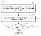
図8は、本実施形態に係るeNB2の動作の一例(処理700)を示すフローチャートである。すでに説明したように、送信端末は、無線リソース割り当ての有効サイドリンク制御期間数をeNB2によって設定されてもよい。図8は、scheduled resource allocation(sidelink transmission mode 1)の場合を示している。ブロック801では、eNB2は、サイドリンク送信のための無線リソース割り当ての有効サイドリンク制御期間数を決定する。ブロック802では、eNB2は、複数のサイドリンク制御期間(PSCCH期間)でのサイドリンク送信が許可されることを示すサイドリンク・スケジューリング・グラントをUE1(送信端末)に送信する。すなわち、当該サイドリンク・スケジューリング・グラントは、PSCCH送信リソース割り当て、PSSCH送信リソース割り当て、及びPSSCH送信リソース割り当てが有効とされるサイドリンク制御期間数を示す。
FIG. 8 is a flowchart showing an example (process 700) of the operation of the
<第2の実施形態>
本実施形態では、第1の実施形態で説明されたサイドリンク送信の変形例が説明される。本実施形態に係る無線通信システムの構成例は図4と同様である。本実施形態では、複数のサイドリンク制御期間にわたるPSSCHリソース割り当てを無効化(又はキャンセル)するための手順について説明する。
<Second embodiment>
In this embodiment, a modification of the side link transmission described in the first embodiment will be described. The configuration example of the wireless communication system according to the present embodiment is the same as that in FIG. In this embodiment, a procedure for invalidating (or canceling) PSSCH resource allocation over a plurality of side link control periods will be described.
いくつかの実装において、送信端末(e.g., UE1A)は、第j番目のサイドリンク制御期間でのサイドリンク制御情報(スケジューリング割当情報)に基づく第(j+1)番目又はそれ以降のデータ送信(PSSCH送信)のための無線リソース割り当てが無効化されることを示すサイドリンク制御情報を第(j+1)番目又はそれ以降のサイドリンク制御期間のいずれかにおいて受信端末(e.g., UE1B)に送信するよう構成されてもよい。言い換えると、送信端末は、複数のサイドリンク制御期間にわたって有効化されている第j番目サイドリンク制御期間でのPSSCHスケジューリング割り当て(SCI format 0)を無効化(又はキャンセル)するために、スケジューリング割り当ての無効化(キャンセル)を示すサイドリンク制御情報を第(j+1)番目又はそれ以降のサイドリンク制御期間のいずれかで送信してもよい。 In some implementations, the transmitting terminal (eg, UE1A) transmits the (j + 1) th or subsequent data based on the side link control information (scheduling allocation information) in the jth side link control period (s). Sidelink control information indicating that the radio resource allocation for PSSCH transmission) is invalidated to the receiving terminal (eg, UE1B) in either the (j + 1) th or later sidelink control period. It may be configured to do so. In other words, the transmitting terminal allocates the scheduling allocation to invalidate (or cancel) the PSSCH scheduling allocation (SCI format 0) in the jth side link control period that has been enabled over multiple side link control periods. The side link control information indicating invalidation (cancellation) may be transmitted in either the (j + 1) th or later side link control period.
スケジューリング割り当ての無効化(キャンセル)を示すサイドリンク制御情報は、スケジューリング割り当ての有効区間数の予約値(例えば、8ビットの場合には11111111といった値)が用いられてもよい。これに代えて、スケジューリング割り当ての無効化(キャンセル)を示すサイドリンク制御情報は、スケジューリング割り当ての無効化を示すフラグを含んでもよい。 As the side link control information indicating invalidation (cancellation) of the scheduling allocation, a reserved value of the number of valid intervals of the scheduling allocation (for example, a value such as 11111111 in the case of 8 bits) may be used. Alternatively, the side link control information indicating the invalidation (cancellation) of the scheduling allocation may include a flag indicating the invalidation of the scheduling allocation.
なお、送信端末と受信端末との間で複数のスケジューリング割り当てが有効されてもよい。この場合、送信端末からの無効化(キャンセル)を示す情報に基づいて、受信端末は、全ての有効なスケジューリング割り当てを無効化してもよい。これに代えて、送信端末は、複数の有効なスケジューリング割り当てのうち無効化されるべきスケジューリング割り当てを示す識別子を受信端末に送信してもよい。 Note that a plurality of scheduling assignments may be enabled between the transmitting terminal and the receiving terminal. In this case, the receiving terminal may invalidate all valid scheduling assignments based on the information indicating invalidation (cancellation) from the transmitting terminal. Alternatively, the transmitting terminal may transmit to the receiving terminal an identifier indicating a scheduling allocation that should be invalidated out of a plurality of valid scheduling assignments.
さらに又はこれに代えて、いくつかの実装において、受信端末(e.g., UE1B)は、複数のサイドリンク制御期間にわたって有効化されているスケジューリング割り当てを自律的に無効化(又はキャンセル)してもよい。例えば、受信端末(e.g., UE1B)は、第(j+1)番目又はそれ以降のサイドリンク制御期間において、所定期間のあいだ送信端末(e.g., UE1A)からのPSSCHでのデータ受信が発生しない場合に、第j番目サイドリンク制御期間において有効化されたスケジューリング割り当て(i.e., PSSCHリソース割り当て)を無効化してもよい。 Further or instead, in some implementations, the receiving terminal (eg, UE1B) may autonomously invalidate (or cancel) scheduling allocations that are in effect over multiple sidelink control periods. .. For example, when the receiving terminal (eg, UE1B) does not receive data on PSSCH from the transmitting terminal (eg, UE1A) during a predetermined period in the (j + 1) th or later side link control period. In addition, the scheduling allocation (ie, PSSCH resource allocation) enabled during the jth side link control period may be invalidated.
複数のサイドリンク制御期間にわたってスケジューリング割り当て(i.e., PSSCHリソース割り当て)が有効化される場合、送信端末のバッファに送信されるべきデータがない(つまり、サイドリンク送信が完了した)ために第(j+1)番目又はそれ以降のサイドリンク制御期間においてPSSCHでのデータ送信が発生しないにも関わらず、有効サイドリンク制御期間内の各サイドリンク制御期間において受信端末がPSSCHの受信を試みてしまう可能性がある。このような無駄な受信動作は、受信端末における不要な電力消費や送信機会の減少を引き起こす。本実施形態で説明されたスケジューリング割り当ての無効化手順によれば、このような弊害を抑制できる。 When scheduling allocation (ie, PSSCH resource allocation) is enabled over multiple sidelink control periods, the first (j) because there is no data to be transmitted in the sending terminal's buffer (that is, sidelink transmission is complete). +1) It is possible that the receiving terminal attempts to receive PSSCH in each side link control period within the valid side link control period even though data transmission in PSSCH does not occur in the third or subsequent side link control period. There is sex. Such useless reception operation causes unnecessary power consumption in the receiving terminal and reduction of transmission opportunities. According to the scheduling allocation invalidation procedure described in the present embodiment, such an adverse effect can be suppressed.
図9は、本実施形態に係る送信端末の動作の一例(処理900)を示すフローチャートである。ブロック901では、送信端末は、複数のサイドリンク制御期間(PSCCH期間)のためのPSSCHリソース割り当てが有効である間にデータ送信が完了したことを判定する。ブロック902では、送信端末は、複数のサイドリンク制御期間(PSCCH期間)のためのPSSCHリソース割り当てが無効化されることを示すサイドリンク制御情報を受信端末に送信する。
FIG. 9 is a flowchart showing an example (process 900) of the operation of the transmitting terminal according to the present embodiment. At
図10は、本実施形態に係る受信端末の動作の一例(処理1000)を示すフローチャートである。ブロック1001では、受信端末は、複数のサイドリンク制御期間(PSCCH期間)のためのPSSCHリソース割り当てが有効である間に、所定期間のあいだ送信端末からのPSSCHでのデータ受信が発生しないことを検出する。ブロック1002では、受信端末は、複数のサイドリンク制御期間(PSCCH期間)のためのPSSCHリソース割り当てを自律的に無効化する。
FIG. 10 is a flowchart showing an example (process 1000) of the operation of the receiving terminal according to the present embodiment. In
<第3の実施形態>
本実施形態では、第1の実施形態で説明されたサイドリンク送信の変形例が説明される。本実施形態に係る無線通信システムの構成例は図4と同様である。本実施形態では、送信端末(e.g., UE1A)は、複数のサイドリンク制御期間にわたるPSSCHリソース割り当てに関する制限を自律的に又はeNB2からの指示に従って当該送信端末に設定するよう構成されている。本実施形態では、セル21内の特定のUE1又は特定のUEグループに対して個別に制限が設定される例を示す。
<Third embodiment>
In this embodiment, a modification of the side link transmission described in the first embodiment will be described. The configuration example of the wireless communication system according to the present embodiment is the same as that in FIG. In the present embodiment, the transmitting terminal (eg, UE1A) is configured to autonomously set restrictions on PSSCH resource allocation over a plurality of side link control periods or according to instructions from eNB2. In this embodiment, an example in which restrictions are individually set for a specific UE1 or a specific UE group in the
いくつかの実装において、送信端末は、eNB2のセル21(つまり、サービングセル)と隣接セルとのセル境界に位置していると推定される場合に、複数のサイドリンク制御期間にわたるPSSCHリソース割り当てに関する制限を自律的に又はeNB2からの指示に従って当該送信端末に設定してもよい。この場合、当該制限は、複数のサイドリンク制御期間にわたるPSSCHリソース割り当ての継続的な有効化を許可しないことであってもよい。これに代えて、当該制限は、PSSCHリソース割り当てが有効とされるサイドリンク制御期間の数(有効サイドリンク制御期間数)に上限値を定めることであってもよい。 In some implementations, the transmitting terminal is presumed to be located at the cell boundary between cell 21 (ie, serving cell) of eNB2 and an adjacent cell, with restrictions on PSSCH resource allocation over multiple sidelink control periods. May be set to the transmitting terminal autonomously or according to the instruction from eNB2. In this case, the limitation may not allow continuous activation of PSSCH resource allocation over multiple sidelink control periods. Instead, the limitation may be to set an upper limit on the number of side link control periods for which PSSCH resource allocation is valid (the number of effective side link control periods).
送信端末がセル境界に位置していることは、以下の条件(a)〜(d)のうちいずれか又は任意の組み合せによって判定されてもよい:
(a)サービングセル21のダウンリンク信号の受信品質(Reference Signal Received Power(RSRP)又はReference Signal Received Quality(RSRQ))が所定値以下、
(b)隣接セルのダウンリンク信号の受信品質が所定値以上、
(c)サービングセル21のeNB2からの距離が所定値以上、及び
(d)隣接セルのeNBからの距離が所定値以下。
The fact that the transmitting terminal is located at the cell boundary may be determined by any or any combination of the following conditions (a) to (d):
(A) The reception quality (Reference Signal Received Power (RSRP) or Reference Signal Received Quality (RSRQ)) of the downlink signal of the serving
(B) The reception quality of the downlink signal of the adjacent cell is equal to or higher than the predetermined value.
(C) The distance of the serving
なお、送信端末がeNB2のセル21(つまり、サービングセル)と隣接セルとのセル境界に位置していると推定される場合、送信端末は隣接セルのUE又はeNBに干渉を与えるおそれがある。したがって、言い換えると、送信端末は、隣接セルのUE又はeNBに干渉を与えるおそれがある場合に、複数のサイドリンク制御期間にわたるPSSCHリソース割り当てに関する制限を自律的に又はeNB2からの指示に従って当該送信端末に設定してもよい。
If it is presumed that the transmitting terminal is located at the cell boundary between the cell 21 (that is, the serving cell) of the
図11は、本実施形態に係る送信端末の動作の一例(処理1100)を示すフローチャートである。ブロック1101では、送信端末は、セル境界に位置していることを検出する。ブロック1102では、送信端末は、複数のサイドリンク制御期間(PSCCH期間)のためのPSSCHリソース割り当てに関する制限を設定する。
FIG. 11 is a flowchart showing an example (process 1100) of the operation of the transmitting terminal according to the present embodiment. At
セル境界に位置する送信端末によるサイドリンク送信は、隣接セルで行われるサイドリンク送信又はアップリンク送信に干渉を及ぼすおそれがある。本実施形態では、複数のサイドリンク制御期間にわたるPSSCHリソース割り当てに関する制限を送信端末に設定できるため、送信端末が隣接セルで行われるサイドリンク送信又はアップリンク送信に継続的に干渉を及ぼす状況を回避できる。 Sidelink transmission by a transmitting terminal located at the cell boundary may interfere with sidelink transmission or uplink transmission performed in an adjacent cell. In the present embodiment, since the restriction on PSSCH resource allocation over a plurality of side link control periods can be set on the transmitting terminal, the situation where the transmitting terminal continuously interferes with the side link transmission or the uplink transmission performed in the adjacent cell is avoided. it can.
<第4の実施形態>
本実施形態では、第1の実施形態で説明されたサイドリンク送信の変形例が説明される。本実施形態に係る無線通信システムの構成例は図4と同様である。本実施形態では、送信端末(e.g., UE1A)は、複数のサイドリンク制御期間にわたるPSSCHリソース割り当てに関する制限をeNB2からの指示に従って当該送信端末に設定するよう構成されている。本実施形態では、セル21内の特定のUE1又は特定のUEグループに対して個別に制限が設定される例を示す。
<Fourth Embodiment>
In this embodiment, a modification of the side link transmission described in the first embodiment will be described. The configuration example of the wireless communication system according to the present embodiment is the same as that in FIG. In the present embodiment, the transmitting terminal (eg, UE1A) is configured to set a restriction on PSSCH resource allocation over a plurality of side link control periods on the transmitting terminal according to an instruction from
いくつかの実装においてeNB2は、セル21内で行われるサイドリンク送信の数(又はサイドリンク送信端末の数)が所定値を超える場合に、セル21内のサイドリンク送信端末の一部又は全てに対して、複数のサイドリンク制御期間にわたるPSSCHリソース割り当てに関する制限を設定してもよい。この場合、当該制限は、PSSCHリソース割り当てが有効とされるサイドリンク制御期間の数(有効サイドリンク制御期間数)に下限値(2以上)を定めることであってもよい。これにより、eNB2は、セル21内で行われるサイドリンク送信の数(サイドリンク送信端末の数)が大きい場合に、PSCCH送信の発生回数を減らすことができる。すなわち、PSCCHリソースプールの使用率を低減できる。したがって、互いに近接する複数のサイドリンク送信端末による複数のPSCCH送信が同一無線リソースで行われる衝突が発生する確率を低減できる。
In some implementations, the
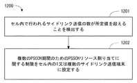
図12は、本実施形態に係るeNB2の動作の一例(処理1200)を示すフローチャートである。ブロック1201では、eNB2は、セル21内で行われるサイドリンク送信(D2D送信)の数が所定値を超えることを検出する。ブロック1202では、eNB2は、複数のサイドリンク制御期間(PSCCH期間)のためのPSSCHリソース割り当てに関する制限をセル21内の1又は複数のサイドリンク(D2D)送信端末に設定する。
FIG. 12 is a flowchart showing an example (process 1200) of the operation of the
最後に、上述の複数の実施形態に係るUE1の構成例について説明する。図13は、UE1の構成例を示すブロック図である。上述した送信端末としてのUE1及び受信端末としてのUE1はいずれも図13に示される構成を有してもよい。Radio Frequency(RF)トランシーバ1301は、eNB2と通信するためにアナログRF信号処理を行う。RFトランシーバ1301により行われるアナログRF信号処理は、周波数アップコンバージョン、周波数ダウンコンバージョン、及び増幅を含む。RFトランシーバ1301は、アンテナ1302及びベースバンドプロセッサ1303と結合される。すなわち、RFトランシーバ1301は、変調シンボルデータ(又はOFDMシンボルデータ)をベースバンドプロセッサ1303から受信し、送信RF信号を生成し、送信RF信号をアンテナ1302に供給する。また、RFトランシーバ1301は、アンテナ1302によって受信された受信RF信号に基づいてベースバンド受信信号を生成し、これをベースバンドプロセッサ1303に供給する。
Finally, a configuration example of UE1 according to the above-described plurality of embodiments will be described. FIG. 13 is a block diagram showing a configuration example of UE1. Both the UE1 as the transmitting terminal and the UE1 as the receiving terminal described above may have the configuration shown in FIG. Radio Frequency (RF)
ベースバンドプロセッサ1303は、無線通信のためのデジタルベースバンド信号処理(データプレーン処理)とコントロールプレーン処理を行う。デジタルベースバンド信号処理は、(a) データ圧縮/復元、(b) データのセグメンテーション/コンカテネーション、(c) 伝送フォーマット(伝送フレーム)の生成/分解、(d) 伝送路符号化/復号化、(e) 変調(シンボルマッピング)/復調、及び(f) Inverse Fast Fourier Transform(IFFT)によるOFDMシンボルデータ(ベースバンドOFDM信号)の生成などを含む。一方、コントロールプレーン処理は、レイヤ1(e.g., 送信電力制御)、レイヤ2(e.g., 無線リソース管理、及びhybrid automatic repeat request(HARQ)処理)、及びレイヤ3(e.g., アタッチ、モビリティ、及び通話管理に関するシグナリング)の通信管理を含む。
The
例えば、LTEおよびLTE-Advancedの場合、ベースバンドプロセッサ1303によるデジタルベースバンド信号処理は、Packet Data Convergence Protocol(PDCP)レイヤ、Radio Link Control(RLC)レイヤ、MACレイヤ、およびPHYレイヤの信号処理を含んでもよい。また、ベースバンドプロセッサ1303によるコントロールプレーン処理は、Non-Access Stratum(NAS)プロトコル、RRCプロトコル、及びMAC CEの処理を含んでもよい。
For example, for LTE and LTE-Advanced, digital baseband signal processing by
ベースバンドプロセッサ1303は、デジタルベースバンド信号処理を行うモデム・プロセッサ(e.g., Digital Signal Processor(DSP))とコントロールプレーン処理を行うプロトコルスタック・プロセッサ(e.g., Central Processing Unit(CPU)、又はMicro Processing Unit(MPU))を含んでもよい。この場合、コントロールプレーン処理を行うプロトコルスタック・プロセッサは、後述するアプリケーションプロセッサ1304と共通化されてもよい。
The
アプリケーションプロセッサ1304は、CPU、MPU、マイクロプロセッサ、又はプロセッサコアとも呼ばれる。アプリケーションプロセッサ1304は、複数のプロセッサ(複数のプロセッサコア)を含んでもよい。アプリケーションプロセッサ1304は、メモリ1306又は図示されていないメモリから読み出されたシステムソフトウェアプログラム(Operating System(OS))及び様々なアプリケーションプログラム(例えば、通話アプリケーション、WEBブラウザ、メーラ、カメラ操作アプリケーション、音楽再生アプリケーション)を実行することによって、UE1の各種機能を実現する。
The
いくつかの実装において、図13に破線(1305)で示されているように、ベースバンドプロセッサ1303及びアプリケーションプロセッサ1304は、1つのチップ上に集積されてもよい。言い換えると、ベースバンドプロセッサ1303及びアプリケーションプロセッサ1304は、1つのSystem on Chip(SoC)デバイス1305として実装されてもよい。SoCデバイスは、システムLarge Scale Integration(LSI)またはチップセットと呼ばれることもある。
In some implementations, the
メモリ1306は、揮発性メモリ若しくは不揮発性メモリ又はこれらの組合せである。メモリ1306は、物理的に独立した複数のメモリデバイスを含んでもよい。揮発性メモリは、例えば、Static Random Access Memory(SRAM)若しくはDynamic RAM(DRAM)又はこれらの組み合わせである。不揮発性メモリは、マスクRead Only Memory(MROM)、Electrically Erasable Programmable ROM(EEPROM)、フラッシュメモリ、若しくはハードディスクドライブ、又はこれらの任意の組合せである。例えば、メモリ1306は、ベースバンドプロセッサ1303、アプリケーションプロセッサ1304、及びSoC1305からアクセス可能な外部メモリデバイスを含んでもよい。メモリ1306は、ベースバンドプロセッサ1303内、アプリケーションプロセッサ1304内、又はSoC1305内に集積された内蔵メモリデバイスを含んでもよい。さらに、メモリ1306は、Universal Integrated Circuit Card(UICC)内のメモリを含んでもよい。
The
メモリ1306は、上述の複数の実施形態で説明されたUE1による処理を行うための命令群およびデータを含むソフトウェアモジュール(コンピュータプログラム)を格納してもよい。いくつかの実装において、ベースバンドプロセッサ1303又はアプリケーションプロセッサ1304は、当該ソフトウェアモジュールをメモリ1306から読み出して実行することで、上述の実施形態で説明されたUE1の処理を行うよう構成されてもよい。
The
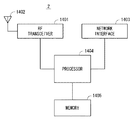
図14は、上述の実施形態に係る基地局(eNB)2の構成例を示すブロック図である。図14を参照すると、基地局2は、RFトランシーバ1401、ネットワークインターフェース1403、プロセッサ1404、及びメモリ1405を含む。RFトランシーバ1401は、無線端末1と通信するためにアナログRF信号処理を行う。RFトランシーバ1401は、複数のトランシーバを含んでもよい。RFトランシーバ1401は、アンテナ1402及びプロセッサ1404と結合される。RFトランシーバ1401は、変調シンボルデータ(又はOFDMシンボルデータ)をプロセッサ1404から受信し、送信RF信号を生成し、送信RF信号をアンテナ1402に供給する。また、RFトランシーバ1401は、アンテナ1402によって受信された受信RF信号に基づいてベースバンド受信信号を生成し、これをプロセッサ1404に供給する。
FIG. 14 is a block diagram showing a configuration example of the base station (eNB) 2 according to the above-described embodiment. Referring to FIG. 14,
ネットワークインターフェース1403は、ネットワークノード(e.g., Mobility Management Entity (MME)およびServing Gateway (S-GW))と通信するために使用される。ネットワークインターフェース1403は、例えば、IEEE 802.3 seriesに準拠したネットワークインターフェースカード(NIC)を含んでもよい。
プロセッサ1404は、無線通信のためのデジタルベースバンド信号処理(データプレーン処理)とコントロールプレーン処理を行う。例えば、LTEおよびLTE-Advancedの場合、プロセッサ1404によるデジタルベースバンド信号処理は、PDCPレイヤ、RLCレイヤ、MACレイヤ、およびPHYレイヤの信号処理を含んでもよい。また、プロセッサ1404によるコントロールプレーン処理は、S1プロトコル、RRCプロトコル、及びMAC CEの処理を含んでもよい。
プロセッサ1404は、複数のプロセッサを含んでもよい。例えば、プロセッサ1404は、デジタルベースバンド信号処理を行うモデム・プロセッサ(e.g., DSP)とコントロールプレーン処理を行うプロトコルスタック・プロセッサ(e.g., CPU又はMPU)を含んでもよい。
メモリ1405は、揮発性メモリ及び不揮発性メモリの組み合わせによって構成される。揮発性メモリは、例えば、SRAM若しくはDRAM又はこれらの組み合わせである。不揮発性メモリは、例えば、MROM、PROM、フラッシュメモリ、若しくはハードディスクドライブ、又はこれらの組合せである。メモリ1405は、プロセッサ1404から離れて配置されたストレージを含んでもよい。この場合、プロセッサ1404は、ネットワークインターフェース1403又は図示されていないI/Oインタフェースを介してメモリ1405にアクセスしてもよい。
The
メモリ1405は、上述の複数の実施形態で説明された基地局2による処理を行うための命令群およびデータを含むソフトウェアモジュール(コンピュータプログラム)を格納してもよい。いくつかの実装において、プロセッサ1404は、当該ソフトウェアモジュールをメモリ1405から読み出して実行することで、上述の実施形態で説明された基地局2の処理を行うよう構成されてもよい。
The
図13及び図14を用いて説明したように、上述の実施形態に係るUE1及びeNB2が有するプロセッサの各々は、図面を用いて説明されたアルゴリズムをコンピュータに行わせるための命令群を含む1又は複数のプログラムを実行する。このプログラムは、様々なタイプの非一時的なコンピュータ可読媒体(non-transitory computer readable medium)を用いて格納され、コンピュータに供給することができる。非一時的なコンピュータ可読媒体は、様々なタイプの実体のある記録媒体(tangible storage medium)を含む。非一時的なコンピュータ可読媒体の例は、磁気記録媒体(例えばフレキシブルディスク、磁気テープ、ハードディスクドライブ)、光磁気記録媒体(例えば光磁気ディスク)、Compact Disc Read Only Memory(CD-ROM)、CD-R、CD-R/W、半導体メモリ(例えば、マスクROM、Programmable ROM(PROM)、Erasable PROM(EPROM)、フラッシュROM、Random Access Memory(RAM))を含む。また、プログラムは、様々なタイプの一時的なコンピュータ可読媒体(transitory computer readable medium)によってコンピュータに供給されてもよい。一時的なコンピュータ可読媒体の例は、電気信号、光信号、及び電磁波を含む。一時的なコンピュータ可読媒体は、電線及び光ファイバ等の有線通信路、又は無線通信路を介して、プログラムをコンピュータに供給できる。 As described with reference to FIGS. 13 and 14, each of the processors included in UE1 and eNB2 according to the above embodiment includes 1 or a group of instructions for causing a computer to perform the algorithm described with reference to the drawings. Run multiple programs. This program can be stored and supplied to a computer using various types of non-transitory computer readable media. Non-transitory computer-readable media include various types of tangible storage media. Examples of non-temporary computer-readable media include magnetic recording media (eg flexible disks, magnetic tapes, hard disk drives), magneto-optical recording media (eg magneto-optical disks), Compact Disc Read Only Memory (CD-ROM), CD- Includes R, CD-R / W, semiconductor memory (eg, mask ROM, Programmable ROM (PROM), Erasable PROM (EPROM), flash ROM, Random Access Memory (RAM)). The program may also be supplied to the computer by various types of transient computer readable media. Examples of temporary computer-readable media include electrical, optical, and electromagnetic waves. The temporary computer-readable medium can supply the program to the computer via a wired communication path such as an electric wire and an optical fiber, or a wireless communication path.
<その他の実施形態>
上述の実施形態は、各々独立に実施されてもよいし、適宜組み合わせて実施されてもよい。
<Other Embodiments>
The above-described embodiments may be implemented independently or in combination as appropriate.
上述の実施形態は、LTE-Advanced 及びその改良に限定されるものではなく、他のモバイル通信ネットワーク又はシステムでのD2D通信に適用されてもよい。 The above embodiments are not limited to LTE-Advanced and its improvements, and may be applied to D2D communication in other mobile communication networks or systems.
さらに、上述した実施形態は本件発明者により得られた技術思想の適用に関する例に過ぎない。すなわち、当該技術思想は、上述した実施形態のみに限定されるものではなく、種々の変更が可能であることは勿論である。 Furthermore, the above-described embodiment is merely an example relating to the application of the technical idea obtained by the inventor of the present invention. That is, the technical idea is not limited to the above-described embodiment, and it goes without saying that various changes can be made.
この出願は、2015年7月15日に出願された日本出願特願2015−141124を基礎とする優先権を主張し、その開示の全てをここに取り込む。 This application claims priority on the basis of Japanese application Japanese Patent Application No. 2015-141124 filed on July 15, 2015, and incorporates all of its disclosures herein.
例えば、上記の実施形態の一部又は全部は、以下の付記のようにも記載され得るが、以下には限られない。
(付記1)
少なくとも1つの無線トランシーバと、
前記少なくとも1つの無線トランシーバに結合され、周期的なdevice-to-device(D2D)制御期間に従って基地局を介さずに他の無線端末へのデータ送信を行うよう構成された少なくとも1つのプロセッサと、
を備え、
各D2D制御期間は、D2D制御情報の送信のために使用可能な複数のサブフレームから成る第1のサブフレーム・プールと、前記D2D制御情報に従う前記データ送信のために使用可能な複数のサブフレームから成る第2のサブフレーム・プールを含み、
前記少なくとも1つのプロセッサは、第1のD2D制御期間内の前記第1のサブフレーム・プール内の1又は複数のサブフレームにおいて第1のD2D制御情報を送信するとともに、前記第1のD2D制御期間内の前記第2のサブフレーム・プール内の1又は複数のサブフレームにおいて前記第1のD2D制御情報に従って前記データ送信を行うよう構成され、
前記第1のD2D制御情報は、前記第1のD2D制御期間内の前記第2のサブフレーム・プール内の1又は複数のサブフレームを特定するための第1の情報要素を含み、
前記第1のD2D制御情報は、さらに、前記第1のD2D制御期間より後の少なくとも1つのD2D制御期間において前記第1のD2D制御情報が有効であるか否かを示す第2の情報要素を含む、
送信端末。
(付記2)
前記少なくとも1つのプロセッサは、前記第1のD2D制御情報が前記少なくとも1つのD2D制御期間において引き続き有効とされる場合に、前記少なくとも1つのD2D制御期間において新たなD2D制御情報を送信すること無く前記データ送信を行うよう構成されている、
付記1に記載の送信端末。
(付記3)
前記第2の情報要素は、前記少なくとも1つのD2D制御期間の長さを示す、
付記1又は2に記載の送信端末。
(付記4)
前記第2の情報要素は、前記第1のD2D制御情報に基づく前記データ送信のための無線リソース割り当てが継続されるか否かを示す、
付記1又は2に記載の送信端末。
(付記5)
前記少なくとも1つのプロセッサは、前記第1のD2D制御情報に基づく前記データ送信のための無線リソース割り当てが無効化されることを示す第2のD2D制御情報を前記少なくとも1つのD2D制御期間のいずれかにおいて送信するよう構成されている、
付記1〜4のいずれか1項に記載の送信端末。
(付記6)
前記少なくとも1つのプロセッサは、前記少なくとも1つのD2D制御期間に関する制限を自律的に又は前記基地局からの指示に従って前記送信端末に設定するよう構成されている、
付記1〜5のいずれか1項に記載の送信端末。
(付記7)
前記制限は、(a)前記第1のD2D制御情報の継続的な有効化が許可されないこと、(b)前記少なくとも1つのD2D制御期間の長さに上限値が定められること、又は(c)前記少なくとも1つのD2D制御期間の長さに下限値が定められること、のうち少なくとも1つを含む、
付記6に記載の送信端末。
(付記8)
前記少なくとも1つのプロセッサは、前記送信端末が前記基地局のセルと隣接セルの間のセル境界に位置していると推定される場合に、(a)前記第1のD2D制御情報の継続的な有効化が許可されないこと、又は(b)前記少なくとも1つのD2D制御期間の長さに上限値が定められることを含む前記制限を前記送信端末に設定するよう構成されている、
付記7に記載の送信端末。
(付記9)
前記制限は、前記少なくとも1つのD2D制御期間の長さに下限値が定められることを含み、
前記少なくとも1つのプロセッサは、前記基地局からの指示にしたがって前記下限値を設定する、
付記7に記載の送信端末。
(付記10)
前記少なくとも1つのプロセッサは、前記基地局のセル内で行われるD2D送信の数が所定値を超える場合に、前記基地局からの指示にしたがって前記下限値を設定する、
付記9に記載の送信端末。
(付記11)
送信端末における方法であって、
周期的なdevice-to-device(D2D)制御期間に従って基地局を介さずに受信端末へのデータ送信を行うことを備え、
各D2D制御期間は、D2D制御情報の送信のために使用可能な複数のサブフレームから成る第1のサブフレーム・プールと、前記D2D制御情報に従う前記データ送信のために使用可能な複数のサブフレームから成る第2のサブフレーム・プールを含み、
前記D2D送信を前記行うことは、第1のD2D制御期間内の前記第1のサブフレーム・プール内の1又は複数のサブフレームにおいて第1のD2D制御情報を送信するとともに、前記第1のD2D制御期間内の前記第2のサブフレーム・プール内の1又は複数のサブフレームにおいて前記第1のD2D制御情報に従って前記データ送信を行うことを含み、
前記第1のD2D制御情報は、前記第1のD2D制御期間内の前記第2のサブフレーム・プール内の1又は複数のサブフレームを特定するための第1の情報要素を含み、
前記第1のD2D制御情報は、さらに、前記第1のD2D制御期間より後の少なくとも1つのD2D制御期間において前記第1のD2D制御情報が有効であるか否かを示す第2の情報要素を含む、
方法。
(付記12)
前記D2D送信を前記行うことは、前記第1のD2D制御情報が前記少なくとも1つのD2D制御期間において引き続き有効とされる場合に、前記少なくとも1つのD2D制御期間において新たなD2D制御情報を送信すること無く前記データ送信を行うことを含む、
付記11に記載の方法。
(付記13)
前記第2の情報要素は、前記少なくとも1つのD2D制御期間の長さを示す、
付記11又は12に記載の方法。
(付記14)
前記第2の情報要素は、前記第1のD2D制御情報に基づく前記データ送信のための無線リソース割り当てが継続されるか否かを示す、
付記11又1は2に記載の方法。
(付記15)
前記第1のD2D制御情報に基づく前記データ送信のための無線リソース割り当てが無効化されることを示す第2のD2D制御情報を前記少なくとも1つのD2D制御期間のいずれかにおいて送信することをさらに備える、
付記11〜14のいずれか1項に記載の方法。
(付記16)
前記少なくとも1つのD2D制御期間に関する制限を自律的に又は前記基地局からの指示に従って設定することをさらに備える、
付記11〜15のいずれか1項に記載の方法。
(付記17)
送信端末における方法をコンピュータに行わせるためのプログラムを格納した非一時的なコンピュータ可読媒体であって、
前記方法は、周期的なdevice-to-device(D2D)制御期間に従って基地局を介さずに受信端末へのデータ送信を行うことを備え、
各D2D制御期間は、D2D制御情報の送信のために使用可能な複数のサブフレームから成る第1のサブフレーム・プールと、前記D2D制御情報に従う前記データ送信のために使用可能な複数のサブフレームから成る第2のサブフレーム・プールを含み、
前記D2D送信を前記行うことは、第1のD2D制御期間内の前記第1のサブフレーム・プール内の1又は複数のサブフレームにおいて第1のD2D制御情報を送信するとともに、前記第1のD2D制御期間内の前記第2のサブフレーム・プール内の1又は複数のサブフレームにおいて前記第1のD2D制御情報に従って前記データ送信を行うことを含み、
前記第1のD2D制御情報は、前記第1のD2D制御期間内の前記第2のサブフレーム・プール内の1又は複数のサブフレームを特定するための第1の情報要素を含み、
前記第1のD2D制御情報は、さらに、前記第1のD2D制御期間より後の少なくとも1つのD2D制御期間において前記第1のD2D制御情報が有効であるか否かを示す第2の情報要素を含む、
非一時的なコンピュータ可読媒体。
(付記18)
少なくとも1つの無線トランシーバと、
前記少なくとも1つの無線トランシーバに結合され、周期的なdevice-to-device(D2D)制御期間に従って基地局を介さずに送信端末からのデータ受信を行うよう構成された少なくとも1つのプロセッサと、
を備え、
各D2D制御期間は、D2D制御情報の送信のために使用可能な複数のサブフレームから成る第1のサブフレーム・プールと、前記D2D制御情報に従う前記データ受信のために使用可能な複数のサブフレームから成る第2のサブフレーム・プールを含み、
前記少なくとも1つのプロセッサは、第1のD2D制御期間内の前記第1のサブフレーム・プール内の1又は複数のサブフレームにおいて第1のD2D制御情報を受信するとともに、前記第1のD2D制御期間内の前記第2のサブフレーム・プール内の1又は複数のサブフレームにおいて前記第1のD2D制御情報に従って前記データ受信を行うよう構成され、
前記第1のD2D制御情報は、前記第1のD2D制御期間内の前記第2のサブフレーム・プール内の1又は複数のサブフレームを特定するための第1の情報要素を含み、
前記第1のD2D制御情報は、さらに、前記第1のD2D制御期間より後の少なくとも1つのD2D制御期間において前記第1のD2D制御情報が有効であるか否かを示す第2の情報要素を含む、
受信端末。
(付記19)
前記少なくとも1つのプロセッサは、前記第1のD2D制御情報が前記少なくとも1つのD2D制御期間において引き続き有効とされる場合に、前記少なくとも1つのD2D制御期間において新たなD2D制御情報を受信すること無く前記データ受信を行うよう構成されている、
付記18に記載の受信端末。
(付記20)
前記少なくとも1つのプロセッサは、前記少なくとも1つのD2D制御期間内の所定期間のあいだ前記データ受信が発生しない場合に、前記少なくとも1つのD2D制御期間での前記第1のD2D制御情報に基づく無線リソース割り当てを無効化するよう構成されている、
付記18又は19に記載の受信端末。
(付記21)
受信端末における方法であって、
周期的なdevice-to-device(D2D)制御期間に従って基地局を介さずに送信端末からのデータ受信を行うことを備え、
各D2D制御期間は、D2D制御情報の送信のために使用可能な複数のサブフレームから成る第1のサブフレーム・プールと、前記D2D制御情報に従う前記データ受信のために使用可能な複数のサブフレームから成る第2のサブフレーム・プールを含み、
前記データ受信を前記行うことは、第1のD2D制御期間内の前記第1のサブフレーム・プール内の1又は複数のサブフレームにおいて第1のD2D制御情報を受信するとともに、前記第1のD2D制御期間内の前記第2のサブフレーム・プール内の1又は複数のサブフレームにおいて前記第1のD2D制御情報に従って前記データ受信を行うことを含み、
前記第1のD2D制御情報は、前記第1のD2D制御期間内の前記第2のサブフレーム・プール内の1又は複数のサブフレームを特定するための第1の情報要素を含み、
前記第1のD2D制御情報は、さらに、前記第1のD2D制御期間より後の少なくとも1つのD2D制御期間において前記第1のD2D制御情報が有効であるか否かを示す第2の情報要素を含む、
方法。
(付記22)
前記データ受信を前記行うことは、前記第1のD2D制御情報が前記少なくとも1つのD2D制御期間において引き続き有効とされる場合に、前記少なくとも1つのD2D制御期間において新たなD2D制御情報を受信すること無く前記データ受信を行うことを含む、
付記21に記載の方法。
(付記23)
前記少なくとも1つのD2D制御期間内の所定期間のあいだ前記データ受信が発生しない場合に、前記少なくとも1つのD2D制御期間での前記第1のD2D制御情報に基づく無線リソース割り当てを無効化することをさらに備える、
付記21又は22に記載の方法。
(付記24)
受信端末における方法をコンピュータに行わせるためのプログラムを格納した非一時的なコンピュータ可読媒体であって、
前記方法は、周期的なdevice-to-device(D2D)制御期間に従って基地局を介さずに送信端末からのデータ受信を行うことを備え、
各D2D制御期間は、D2D制御情報の送信のために使用可能な複数のサブフレームから成る第1のサブフレーム・プールと、前記D2D制御情報に従う前記データ受信のために使用可能な複数のサブフレームから成る第2のサブフレーム・プールを含み、
前記データ受信を前記行うことは、第1のD2D制御期間内の前記第1のサブフレーム・プール内の1又は複数のサブフレームにおいて第1のD2D制御情報を受信するとともに、前記第1のD2D制御期間内の前記第2のサブフレーム・プール内の1又は複数のサブフレームにおいて前記第1のD2D制御情報に従って前記データ受信を行うことを含み、
前記第1のD2D制御情報は、前記第1のD2D制御期間内の前記第2のサブフレーム・プール内の1又は複数のサブフレームを特定するための第1の情報要素を含み、
前記第1のD2D制御情報は、さらに、前記第1のD2D制御期間より後の少なくとも1つのD2D制御期間において前記第1のD2D制御情報が有効であるか否かを示す第2の情報要素を含む、
非一時的なコンピュータ可読媒体。
(付記25)
基地局であって、
セル内の複数の無線端末と通信するよう構成された無線トランシーバと、
周期的なdevice-to-device(D2D)制御期間に従う第1の無線端末から第2の無線端末への前記基地局を介さないデータ送信を制御するよう構成された少なくとも1つのプロセッサと、
を備え、
各D2D制御期間は、D2D制御情報の送信のために使用可能な複数のサブフレームから成る第1のサブフレーム・プールと、前記D2D制御情報に従う前記データ送信のために使用可能な複数のサブフレームから成る第2のサブフレーム・プールを含み、
前記少なくとも1つのプロセッサは、第1のD2D制御期間内での前記D2D制御情報の送信及び前記データ送信のための無線リソース割り当てを示すとともに、前記第1のD2D制御期間より後の少なくとも1つのD2D制御期間においても前記無線リソース割り当てが有効であることを示すD2Dグラントメッセージを前記第1の無線端末に送信するよう構成されている、
基地局。
(付記26)
前記少なくとも1つのプロセッサは、前記少なくとも1つのD2D制御期間に関する制限を前記第1の無線端末に設定するよう構成されている、
付記25に記載の基地局。
(付記27)
前記制限は、前記少なくとも1つのD2D制御期間の長さに下限値が定められることを含む、
付記26に記載の基地局。
(付記28)
前記少なくとも1つのプロセッサは、前記セル内で行われるD2D送信の数が所定値を超える場合に前記下限値を前記第1の無線端末に設定するよう構成されている、
付記27に記載の基地局。
(付記29)
基地局における方法であって、
周期的なdevice-to-device(D2D)制御期間に従う第1の無線端末から第2の無線端末への前記基地局を介さないデータ送信を制御することを備え、
各D2D制御期間は、D2D制御情報の送信のために使用可能な複数のサブフレームから成る第1のサブフレーム・プールと、前記D2D制御情報に従う前記データ送信のために使用可能な複数のサブフレームから成る第2のサブフレーム・プールを含み、
前記制御することは、第1のD2D制御期間内での前記D2D制御情報の送信及び前記データ送信のための無線リソース割り当てを示すとともに、前記第1のD2D制御期間より後の少なくとも1つのD2D制御期間においても前記無線リソース割り当てが有効であることを示すD2Dグラントメッセージを前記第1の無線端末に送信することを含む、
方法。
(付記30)
前記制御することは、少なくとも1つのD2D制御期間に関する制限を前記第1の無線端末に設定することを含む、
付記29に記載の方法。
(付記31)
前記制限は、前記少なくとも1つのD2D制御期間の長さに下限値が定められることを含む、
付記30に記載の方法。
(付記32)
前記設定することは、前記基地局のセル内で行われるD2D送信の数が所定値を超える場合に前記下限値を前記第1の無線端末に設定することを含む、
付記31に記載の方法。
(付記33)
基地局における方法をコンピュータに行わせるためのプログラムを格納した非一時的なコンピュータ可読媒体であって、
前記方法は、周期的なdevice-to-device(D2D)制御期間に従う第1の無線端末から第2の無線端末への前記基地局を介さないデータ送信を制御することを備え、
各D2D制御期間は、D2D制御情報の送信のために使用可能な複数のサブフレームから成る第1のサブフレーム・プールと、前記D2D制御情報に従う前記データ送信のために使用可能な複数のサブフレームから成る第2のサブフレーム・プールを含み、
前記制御することは、第1のD2D制御期間内での前記D2D制御情報の送信及び前記データ送信のための無線リソース割り当てを示すとともに、前記第1のD2D制御期間より後の少なくとも1つのD2D制御期間においても前記無線リソース割り当てが有効であることを示すD2Dグラントメッセージを前記第1の無線端末に送信することを含む、
非一時的なコンピュータ可読媒体。
For example, some or all of the above embodiments may also be described, but not limited to:
(Appendix 1)
With at least one wireless transceiver,
With at least one processor coupled to the at least one radio transceiver and configured to transmit data to another radio terminal without going through a base station according to a periodic device-to-device (D2D) control period.
With
Each D2D control period includes a first subframe pool consisting of a plurality of subframes available for transmission of D2D control information and a plurality of subframes available for transmission of the data according to the D2D control information. Includes a second subframe pool consisting of
The at least one processor transmits the first D2D control information in one or more subframes in the first subframe pool within the first D2D control period, and the first D2D control period. One or more subframes in the second subframe pool of the data are configured to transmit the data according to the first D2D control information.
The first D2D control information includes a first information element for identifying one or more subframes in the second subframe pool within the first D2D control period.
The first D2D control information further includes a second information element indicating whether or not the first D2D control information is valid in at least one D2D control period after the first D2D control period. Including,
Sending terminal.
(Appendix 2)
The at least one processor, said, without transmitting new D2D control information during the at least one D2D control period, if the first D2D control information is still valid during the at least one D2D control period. It is configured to send data,
The transmitting terminal according to
(Appendix 3)
The second information element indicates the length of the at least one D2D control period.
The transmitting terminal according to
(Appendix 4)
The second information element indicates whether or not the radio resource allocation for the data transmission based on the first D2D control information is continued.
The transmitting terminal according to
(Appendix 5)
The at least one processor provides the second D2D control information indicating that the radio resource allocation for the data transmission based on the first D2D control information is invalidated in any of the at least one D2D control period. Is configured to send in,
The transmitting terminal according to any one of
(Appendix 6)
The at least one processor is configured to autonomously set a limit on the at least one D2D control period on the transmitting terminal or in accordance with instructions from the base station.
The transmitting terminal according to any one of
(Appendix 7)
The restrictions are that (a) continuous activation of the first D2D control information is not permitted, (b) an upper limit is set for the length of at least one D2D control period, or (c). A lower limit is set for the length of at least one D2D control period, including at least one of the above.
The transmitting terminal according to Appendix 6.
(Appendix 8)
When the transmitting terminal is presumed to be located at the cell boundary between the cell of the base station and the adjacent cell, the at least one processor (a) continuously of the first D2D control information. It is configured to set such restrictions on the transmitting terminal, including that activation is not permitted or (b) an upper limit is set on the length of the at least one D2D control period.
The transmitting terminal according to Appendix 7.
(Appendix 9)
The limitation includes setting a lower limit on the length of the at least one D2D control period.
The at least one processor sets the lower limit according to an instruction from the base station.
The transmitting terminal according to Appendix 7.
(Appendix 10)
The at least one processor sets the lower limit according to an instruction from the base station when the number of D2D transmissions performed in the cell of the base station exceeds a predetermined value.
The transmitting terminal according to Appendix 9.
(Appendix 11)
It is a method in the transmitting terminal
It is equipped with data transmission to the receiving terminal without going through a base station according to a periodic device-to-device (D2D) control period.
Each D2D control period includes a first subframe pool consisting of a plurality of subframes available for transmission of D2D control information and a plurality of subframes available for transmission of the data according to the D2D control information. Includes a second subframe pool consisting of
Performing the D2D transmission transmits the first D2D control information in one or more subframes in the first subframe pool within the first D2D control period, and also transmits the first D2D. Including performing the data transmission in accordance with the first D2D control information in one or more subframes in the second subframe pool within the control period.
The first D2D control information includes a first information element for identifying one or more subframes in the second subframe pool within the first D2D control period.
The first D2D control information further includes a second information element indicating whether or not the first D2D control information is valid in at least one D2D control period after the first D2D control period. Including,
Method.
(Appendix 12)
Performing the D2D transmission means transmitting new D2D control information in the at least one D2D control period when the first D2D control information is still valid in the at least one D2D control period. Including performing the data transmission without
The method according to Appendix 11.
(Appendix 13)
The second information element indicates the length of the at least one D2D control period.
The method according to Appendix 11 or 12.
(Appendix 14)
The second information element indicates whether or not the radio resource allocation for the data transmission based on the first D2D control information is continued.
(Appendix 15)
Further comprising transmitting second D2D control information indicating that the radio resource allocation for the data transmission based on the first D2D control information is invalidated during any of the at least one D2D control period. ,
The method according to any one of Supplementary Notes 11 to 14.
(Appendix 16)
It further comprises setting a limit on the at least one D2D control period autonomously or according to instructions from the base station.
The method according to any one of Supplementary Notes 11 to 15.
(Appendix 17)
A non-transitory computer-readable medium containing a program that allows a computer to perform a method at a transmitting terminal.
The method comprises transmitting data to a receiving terminal according to a periodic device-to-device (D2D) control period without going through a base station.
Each D2D control period includes a first subframe pool consisting of a plurality of subframes available for transmission of D2D control information and a plurality of subframes available for transmission of the data according to the D2D control information. Includes a second subframe pool consisting of
Performing the D2D transmission transmits the first D2D control information in one or more subframes in the first subframe pool within the first D2D control period, and also transmits the first D2D. Including performing the data transmission in accordance with the first D2D control information in one or more subframes in the second subframe pool within the control period.
The first D2D control information includes a first information element for identifying one or more subframes in the second subframe pool within the first D2D control period.
The first D2D control information further includes a second information element indicating whether or not the first D2D control information is valid in at least one D2D control period after the first D2D control period. Including,
Non-temporary computer-readable medium.
(Appendix 18)
With at least one wireless transceiver,
With at least one processor coupled to the at least one radio transceiver and configured to receive data from a transmitting terminal according to a periodic device-to-device (D2D) control period without going through a base station.
With
Each D2D control period includes a first subframe pool consisting of a plurality of subframes available for transmission of D2D control information and a plurality of subframes available for receiving the data according to the D2D control information. Includes a second subframe pool consisting of
The at least one processor receives the first D2D control information in one or more subframes in the first subframe pool within the first D2D control period, and the first D2D control period. One or more subframes in the second subframe pool of the above are configured to receive the data according to the first D2D control information.
The first D2D control information includes a first information element for identifying one or more subframes in the second subframe pool within the first D2D control period.
The first D2D control information further includes a second information element indicating whether or not the first D2D control information is valid in at least one D2D control period after the first D2D control period. Including,
Receiving terminal.
(Appendix 19)
The at least one processor will not receive new D2D control information during the at least one D2D control period if the first D2D control information is still valid during the at least one D2D control period. It is configured to receive data,
The receiving terminal according to Appendix 18.
(Appendix 20)
The at least one processor allocates radio resources based on the first D2D control information in the at least one D2D control period when the data reception does not occur during a predetermined period within the at least one D2D control period. Is configured to disable
The receiving terminal according to Appendix 18 or 19.
(Appendix 21)
It is a method in the receiving terminal
It is equipped with data reception from a transmitting terminal without going through a base station according to a periodic device-to-device (D2D) control period.
Each D2D control period includes a first subframe pool consisting of a plurality of subframes available for transmission of D2D control information and a plurality of subframes available for receiving the data according to the D2D control information. Includes a second subframe pool consisting of
Performing the data reception receives the first D2D control information in one or more subframes in the first subframe pool within the first D2D control period, and also receives the first D2D. This includes receiving the data according to the first D2D control information in one or more subframes in the second subframe pool within the control period.
The first D2D control information includes a first information element for identifying one or more subframes in the second subframe pool within the first D2D control period.
The first D2D control information further includes a second information element indicating whether or not the first D2D control information is valid in at least one D2D control period after the first D2D control period. Including,
Method.
(Appendix 22)
The data reception is to receive new D2D control information in the at least one D2D control period when the first D2D control information is still valid in the at least one D2D control period. Including receiving the data without
The method according to
(Appendix 23)
Further, invalidating the radio resource allocation based on the first D2D control information in the at least one D2D control period when the data reception does not occur during a predetermined period within the at least one D2D control period. Prepare, prepare
The method according to
(Appendix 24)
A non-transitory computer-readable medium containing a program that allows a computer to perform a method at a receiving terminal.
The method comprises receiving data from a transmitting terminal according to a periodic device-to-device (D2D) control period without going through a base station.
Each D2D control period includes a first subframe pool consisting of a plurality of subframes available for transmission of D2D control information and a plurality of subframes available for receiving the data according to the D2D control information. Includes a second subframe pool consisting of
Performing the data reception receives the first D2D control information in one or more subframes in the first subframe pool within the first D2D control period, and also receives the first D2D. This includes receiving the data according to the first D2D control information in one or more subframes in the second subframe pool within the control period.
The first D2D control information includes a first information element for identifying one or more subframes in the second subframe pool within the first D2D control period.
The first D2D control information further includes a second information element indicating whether or not the first D2D control information is valid in at least one D2D control period after the first D2D control period. Including,
Non-temporary computer-readable medium.
(Appendix 25)
It ’s a base station,
A wireless transceiver configured to communicate with multiple wireless terminals in the cell,
With at least one processor configured to control the transmission of data from the first radio terminal to the second radio terminal via the base station according to a periodic device-to-device (D2D) control period.
With
Each D2D control period includes a first subframe pool consisting of a plurality of subframes available for transmission of D2D control information and a plurality of subframes available for transmission of the data according to the D2D control information. Includes a second subframe pool consisting of
The at least one processor exhibits radio resource allocation for transmission of the D2D control information and data transmission within the first D2D control period, and at least one D2D after the first D2D control period. It is configured to transmit a D2D grant message indicating that the radio resource allocation is valid even during the control period to the first radio terminal.
base station.
(Appendix 26)
The at least one processor is configured to set a limit on the at least one D2D control period on the first radio terminal.
The base station according to Appendix 25.
(Appendix 27)
The limitation includes setting a lower limit on the length of the at least one D2D control period.
The base station according to Appendix 26.
(Appendix 28)
The at least one processor is configured to set the lower limit to the first wireless terminal when the number of D2D transmissions performed in the cell exceeds a predetermined value.
The base station according to Appendix 27.
(Appendix 29)
The method at the base station
It comprises controlling the data transmission from the first radio terminal to the second radio terminal without the base station according to a periodic device-to-device (D2D) control period.
Each D2D control period includes a first subframe pool consisting of a plurality of subframes available for transmission of D2D control information and a plurality of subframes available for transmission of the data according to the D2D control information. Includes a second subframe pool consisting of
The control indicates radio resource allocation for transmission of the D2D control information and data transmission within the first D2D control period, and at least one D2D control after the first D2D control period. Including transmitting a D2D grant message indicating that the radio resource allocation is valid even during the period to the first radio terminal.
Method.
(Appendix 30)
The control includes setting a limit on at least one D2D control period on the first radio terminal.
The method according to Appendix 29.
(Appendix 31)
The limitation includes setting a lower limit on the length of the at least one D2D control period.
The method according to Appendix 30.
(Appendix 32)
The setting includes setting the lower limit value in the first wireless terminal when the number of D2D transmissions performed in the cell of the base station exceeds a predetermined value.
The method according to Appendix 31.
(Appendix 33)
A non-transitory computer-readable medium containing a program that allows a computer to perform a method at a base station.
The method comprises controlling the transmission of data from a first radio terminal to a second radio terminal via the base station according to a periodic device-to-device (D2D) control period.
Each D2D control period includes a first subframe pool consisting of a plurality of subframes available for transmission of D2D control information and a plurality of subframes available for transmission of the data according to the D2D control information. Includes a second subframe pool consisting of
The control indicates radio resource allocation for transmission of the D2D control information and data transmission within the first D2D control period, and at least one D2D control after the first D2D control period. Including transmitting a D2D grant message indicating that the radio resource allocation is valid even during the period to the first radio terminal.
Non-temporary computer-readable medium.
1 UE
2 eNB
1301 radio frequency(RF)トランシーバ
1303 ベースバンドプロセッサ
1304 アプリケーションプロセッサ
1306 メモリ
1401 RFトランシーバ
1404 プロセッサ
1405 メモリ
1 UE
2 eNB
1301 radio frequency (RF)
Claims (1)
前記少なくとも1つの無線トランシーバに結合され、周期的なdevice-to-device(D2D)制御期間に従って基地局を介さずに他の無線端末へのデータ送信を行うよう構成された少なくとも1つのプロセッサと、
を備え、
各D2D制御期間は、D2D制御情報の送信のために使用可能な複数のサブフレームから成る第1のサブフレーム・プールと、前記D2D制御情報に従う前記データ送信のために使用可能な複数のサブフレームから成る第2のサブフレーム・プールを含み、
前記少なくとも1つのプロセッサは、第1のD2D制御期間内の前記第1のサブフレーム・プール内の1又は複数のサブフレームにおいて第1のD2D制御情報を送信するとともに、前記第1のD2D制御期間内の前記第2のサブフレーム・プール内の1又は複数のサブフレームにおいて前記第1のD2D制御情報に従って前記データ送信を行うよう構成され、
前記第1のD2D制御情報は、前記第1のD2D制御期間内の前記第2のサブフレーム・プール内の1又は複数のサブフレームを特定するための第1の情報要素を含み、
前記第1のD2D制御情報は、さらに、前記第1のD2D制御期間より後の少なくとも1つのD2D制御期間において前記第1のD2D制御情報が有効であるか否かを示す第2の情報要素を含む、
送信端末。 With at least one wireless transceiver,
With at least one processor coupled to the at least one radio transceiver and configured to transmit data to another radio terminal without going through a base station according to a periodic device-to-device (D2D) control period.
With
Each D2D control period includes a first subframe pool consisting of a plurality of subframes available for transmission of D2D control information and a plurality of subframes available for transmission of the data according to the D2D control information. Includes a second subframe pool consisting of
The at least one processor transmits the first D2D control information in one or more subframes in the first subframe pool within the first D2D control period, and the first D2D control period. One or more subframes in the second subframe pool of the data are configured to transmit the data according to the first D2D control information.
The first D2D control information includes a first information element for identifying one or more subframes in the second subframe pool within the first D2D control period.
The first D2D control information further includes a second information element indicating whether or not the first D2D control information is valid in at least one D2D control period after the first D2D control period. Including,
Sending terminal.
Priority Applications (1)
| Application Number | Priority Date | Filing Date | Title |
|---|---|---|---|
| JP2023076817A JP7810439B2 (en) | 2015-07-15 | 2023-05-08 | Terminal device method and terminal device |
Applications Claiming Priority (3)
| Application Number | Priority Date | Filing Date | Title |
|---|---|---|---|
| JP2015141124 | 2015-07-15 | ||
| JP2015141124 | 2015-07-15 | ||
| JP2017528273A JP6724917B2 (en) | 2015-07-15 | 2016-05-16 | Terminal and base station and methods thereof |
Related Parent Applications (1)
| Application Number | Title | Priority Date | Filing Date |
|---|---|---|---|
| JP2017528273A Division JP6724917B2 (en) | 2015-07-15 | 2016-05-16 | Terminal and base station and methods thereof |
Related Child Applications (1)
| Application Number | Title | Priority Date | Filing Date |
|---|---|---|---|
| JP2023076817A Division JP7810439B2 (en) | 2015-07-15 | 2023-05-08 | Terminal device method and terminal device |
Publications (3)
| Publication Number | Publication Date |
|---|---|
| JP2020171027A true JP2020171027A (en) | 2020-10-15 |
| JP2020171027A5 JP2020171027A5 (en) | 2021-04-30 |
| JP7414650B2 JP7414650B2 (en) | 2024-01-16 |
Family
ID=57757162
Family Applications (3)
| Application Number | Title | Priority Date | Filing Date |
|---|---|---|---|
| JP2017528273A Active JP6724917B2 (en) | 2015-07-15 | 2016-05-16 | Terminal and base station and methods thereof |
| JP2020102287A Active JP7414650B2 (en) | 2015-07-15 | 2020-06-12 | User equipment (UE) and its method |
| JP2023076817A Active JP7810439B2 (en) | 2015-07-15 | 2023-05-08 | Terminal device method and terminal device |
Family Applications Before (1)
| Application Number | Title | Priority Date | Filing Date |
|---|---|---|---|
| JP2017528273A Active JP6724917B2 (en) | 2015-07-15 | 2016-05-16 | Terminal and base station and methods thereof |
Family Applications After (1)
| Application Number | Title | Priority Date | Filing Date |
|---|---|---|---|
| JP2023076817A Active JP7810439B2 (en) | 2015-07-15 | 2023-05-08 | Terminal device method and terminal device |
Country Status (5)
| Country | Link |
|---|---|
| US (2) | US10492098B2 (en) |
| EP (2) | EP3768022B1 (en) |
| JP (3) | JP6724917B2 (en) |
| CN (4) | CN113923644B (en) |
| WO (1) | WO2017010030A1 (en) |
Cited By (1)
| Publication number | Priority date | Publication date | Assignee | Title |
|---|---|---|---|---|
| JP7432553B2 (en) | 2021-04-20 | 2024-02-16 | ソフトバンク株式会社 | System, wireless terminal device, vehicle, base station, method, and program for HARQ retransmission control in data transmission via direct communication between terminals |
Families Citing this family (35)
| Publication number | Priority date | Publication date | Assignee | Title |
|---|---|---|---|---|
| EP3338482B1 (en) | 2015-08-21 | 2020-12-23 | LG Electronics Inc. | Method for triggering a bsr for sidelink data in a d2d communication system and device therefor |
| US11395325B2 (en) * | 2016-04-01 | 2022-07-19 | Lg Electronics Inc. | Method for transmitting downlink control information for sidelink scheduling in wireless communication system and terminal using same |
| CN109076577B (en) | 2016-04-01 | 2022-01-07 | Lg电子株式会社 | Terminal operation method according to uplink SPS in wireless communication system and terminal using the same |
| CN107371261B (en) * | 2016-05-13 | 2023-05-30 | 中兴通讯股份有限公司 | Resource priority determination method, processing device and system, UE |
| WO2018030788A1 (en) * | 2016-08-09 | 2018-02-15 | 엘지전자 주식회사 | Method whereby terminal transmits and receives sidelink signals in wireless communication system |
| US10736128B2 (en) | 2016-09-30 | 2020-08-04 | Lg Electronics Inc. | Method and apparatus for terminal self-reselecting resource based on priority in wireless communication system |
| WO2018084524A1 (en) * | 2016-11-02 | 2018-05-11 | 엘지전자(주) | Method for performing sidelink transmission in wireless communication system and apparatus therefor |
| US10986610B2 (en) * | 2016-12-29 | 2021-04-20 | Lg Electronics Inc. | Method for transmitting and receiving signal in wireless communication system and apparatus therefor |
| EP3595377B1 (en) * | 2017-05-04 | 2023-06-14 | Huawei Technologies Co., Ltd. | Method, apparatus and system for configuring transmission resource |
| US11038646B2 (en) * | 2017-06-26 | 2021-06-15 | Qualcomm Incorporated | Techniques and apparatuses for shared reference signal transmission and reception |
| US20190053204A1 (en) * | 2017-08-11 | 2019-02-14 | Industrial Technology Research Institute | Method, transmitting node and receiving node for feedback control of sidelink communication |
| CN110120857B (en) * | 2018-02-05 | 2022-01-28 | 中兴通讯股份有限公司 | Method and device for selecting resources |
| US10470143B2 (en) * | 2018-03-13 | 2019-11-05 | Qualcomm Incorporated | Systems and methods for timing synchronization and synchronization source selection for vehicle-to-vehicle communications |
| US11457431B2 (en) * | 2018-08-03 | 2022-09-27 | FG Innovation Company Limited | Sidelink radio resource allocation |
| CN110798297A (en) * | 2018-08-03 | 2020-02-14 | 维沃移动通信有限公司 | A kind of side link information transmission method and terminal |
| WO2020029197A1 (en) * | 2018-08-09 | 2020-02-13 | Nokia Shanghai Bell Co., Ltd. | Methods and devices for v2v communication |
| WO2020044310A1 (en) * | 2018-08-31 | 2020-03-05 | Telefonaktiebolaget Lm Ericsson (Publ) | Methods and systems for autonomous sidelink resource allocation |
| CN110896345B (en) * | 2018-09-13 | 2021-07-09 | 华为技术有限公司 | Method and apparatus for transmitting and receiving sidelink control information |
| US20210306983A1 (en) * | 2018-09-13 | 2021-09-30 | Ntt Docomo, Inc. | User equipment and base station device |
| CN110958689B (en) * | 2018-09-26 | 2022-05-27 | 维沃移动通信有限公司 | Resource allocation method and equipment |
| CN112956275B (en) * | 2018-09-27 | 2024-09-27 | 弗劳恩霍夫应用研究促进协会 | New radio sidechain frame structure |
| MY207668A (en) | 2018-09-28 | 2025-03-11 | Nokia Technologies Oy | Control channel structure design to support v2x traffic |
| US12035312B2 (en) * | 2018-12-29 | 2024-07-09 | Beijing Xiaomi Mobile Software Co., Ltd. | Communication feedback method, user device, and storage medium |
| US12089202B2 (en) * | 2019-01-08 | 2024-09-10 | Lenovo (Beijing) Limited | Method and apparatus for a sidelink transmission |
| EP3928454B1 (en) * | 2019-02-22 | 2026-01-14 | InterDigital Patent Holdings, Inc. | Methods for nr sl multi-sub-channel pscch transmission |
| CN111757454A (en) * | 2019-03-27 | 2020-10-09 | 夏普株式会社 | Method performed by user equipment and user equipment |
| CN111867099B (en) * | 2019-04-30 | 2024-04-05 | 株式会社Kt | Method and device for transmitting and receiving HARQ feedback information of side chain |
| CN111867095B (en) * | 2019-04-30 | 2024-04-16 | 华为技术有限公司 | A communication method and terminal device |
| US12016012B2 (en) * | 2019-05-03 | 2024-06-18 | Lg Electronics Inc. | Method for transmitting sidelink signal in wireless communication system |
| US12250713B2 (en) * | 2019-05-03 | 2025-03-11 | Lg Electronics Inc. | Method and device for selecting transmission resource in NR V2X |
| EP3780674B1 (en) * | 2019-08-16 | 2023-03-08 | Hyundai Motor Company | Method transmitting sidelink data in communication system |
| US11943067B2 (en) * | 2019-10-04 | 2024-03-26 | Huawei Technologies Co., Ltd. | Devices and methods of signaling for resource selection and reservation in sidelink transmission |
| CN113271182B (en) * | 2020-02-14 | 2022-12-06 | 中国移动通信有限公司研究院 | Method and equipment for determining straight-through link process |
| US11812308B2 (en) * | 2020-08-24 | 2023-11-07 | Qualcomm Incorporated | Multiple transmission opportunity resource reservation for sidelink communication |
| JP2022101287A (en) * | 2020-12-24 | 2022-07-06 | 株式会社デンソー | Communication device, communication method, and communication program |
Citations (4)
| Publication number | Priority date | Publication date | Assignee | Title |
|---|---|---|---|---|
| WO2013046468A1 (en) * | 2011-09-30 | 2013-04-04 | 富士通株式会社 | Wireless communication system, mobile station, base station, and method for controlling wireless communication system |
| WO2014014327A1 (en) * | 2012-07-20 | 2014-01-23 | Lg Electronics Inc. | Method and apparatus for transmitting device-to-device related information in wireless communication system |
| WO2015020356A1 (en) * | 2013-08-09 | 2015-02-12 | 주식회사 케이티 | Method for transmitting buffer status report in device-to-device communication, and device thereof |
| WO2015019465A1 (en) * | 2013-08-08 | 2015-02-12 | 富士通株式会社 | Radio communication system, radio communication method, and radio station |
Family Cites Families (22)
| Publication number | Priority date | Publication date | Assignee | Title |
|---|---|---|---|---|
| CN103416012B (en) * | 2011-03-11 | 2016-10-19 | Lg电子株式会社 | Method and device for setting dynamic subframe in wireless communication system |
| CN104145443B (en) | 2012-02-14 | 2017-09-22 | Lg电子株式会社 | Device is to device communication means and apparatus for carrying out the method |
| GB2502275B (en) * | 2012-05-21 | 2017-04-19 | Sony Corp | Telecommunications systems and methods |
| CN104125610B (en) * | 2013-04-28 | 2017-11-10 | 电信科学技术研究院 | Data transmission method for uplink and equipment in D2D communications |
| JP6239280B2 (en) * | 2013-06-27 | 2017-11-29 | 京セラ株式会社 | User terminal, processor and mobile communication system |
| CN104602179B (en) * | 2013-10-31 | 2019-05-07 | 中兴通讯股份有限公司 | A method and user equipment for sending D2D data |
| WO2015065113A1 (en) | 2013-10-31 | 2015-05-07 | 엘지전자(주) | Method and apparatus for performing device-to-device communication in wireless communication system |
| US9854424B2 (en) * | 2013-10-31 | 2017-12-26 | Lg Electronics Inc. | Method and apparatus for device-to-device communication in wireless communication system |
| KR101820460B1 (en) * | 2013-11-07 | 2018-01-22 | 한국전자통신연구원 | Apparatus, system and method for controlling radio resource |
| WO2015080484A1 (en) * | 2013-11-29 | 2015-06-04 | 엘지전자(주) | Method for transmitting and receiving discovery message in wireless communication system, and apparatus for same |
| JP6249796B2 (en) | 2014-01-29 | 2017-12-20 | 三菱電機株式会社 | Synthetic aperture radar signal processing apparatus and synthetic aperture radar signal processing method |
| CN106165524B (en) * | 2014-01-29 | 2020-01-07 | 交互数字专利控股公司 | Resource selection for device-to-device discovery or communication |
| WO2015137685A1 (en) * | 2014-03-11 | 2015-09-17 | 엘지전자(주) | Method for assigning resources in wireless communication system supporting device-to-device direct communication, and apparatus therefor |
| WO2015152580A1 (en) * | 2014-03-30 | 2015-10-08 | 엘지전자(주) | Method for transceiving signal in wireless communication system and apparatus therefor |
| KR101753550B1 (en) * | 2014-04-02 | 2017-07-03 | 엘지전자 주식회사 | Method for transceiving signal in wireless communication system and apparatus therefor |
| JP6391806B2 (en) * | 2014-04-24 | 2018-09-19 | エルジー エレクトロニクス インコーポレイティド | Synchronization signal transmission method and apparatus for D2D communication in a wireless communication system |
| CN105338637B (en) * | 2014-08-07 | 2019-11-19 | 中兴通讯股份有限公司 | D2D communication processing method, device, D2D communication equipment and base station |
| US9735926B2 (en) * | 2014-08-26 | 2017-08-15 | Lg Electronics Inc. | Method and apparatus for data transmission of device-to-device user equipment in wireless communication system |
| WO2016048407A1 (en) * | 2014-09-23 | 2016-03-31 | Fujitsu Limited | Device-to device (d2d) synchronization message signaling |
| JP6621758B2 (en) | 2014-11-14 | 2019-12-18 | 株式会社Nttドコモ | User apparatus, feedback control method, and retransmission control method |
| EP3051736B1 (en) * | 2015-01-30 | 2020-04-29 | Panasonic Intellectual Property Corporation of America | Prioritization in the logical channel prioritization procedure for sidelink logical channels in ProSe direct communications |
| US10064212B2 (en) * | 2015-05-14 | 2018-08-28 | Blackberry Limited | Transmitting a scheduling request for a device-to-device transmission |
-
2016
- 2016-05-16 EP EP20191095.7A patent/EP3768022B1/en active Active
- 2016-05-16 US US15/743,156 patent/US10492098B2/en not_active Ceased
- 2016-05-16 WO PCT/JP2016/002376 patent/WO2017010030A1/en not_active Ceased
- 2016-05-16 CN CN202111214066.7A patent/CN113923644B/en active Active
- 2016-05-16 CN CN201680041216.XA patent/CN107852717B/en active Active
- 2016-05-16 CN CN202111214082.6A patent/CN113923646B/en active Active
- 2016-05-16 EP EP16824016.6A patent/EP3324695B1/en active Active
- 2016-05-16 CN CN202111214081.1A patent/CN113923645B/en active Active
- 2016-05-16 JP JP2017528273A patent/JP6724917B2/en active Active
- 2016-05-16 US US17/535,484 patent/USRE50270E1/en active Active
-
2020
- 2020-06-12 JP JP2020102287A patent/JP7414650B2/en active Active
-
2023
- 2023-05-08 JP JP2023076817A patent/JP7810439B2/en active Active
Patent Citations (4)
| Publication number | Priority date | Publication date | Assignee | Title |
|---|---|---|---|---|
| WO2013046468A1 (en) * | 2011-09-30 | 2013-04-04 | 富士通株式会社 | Wireless communication system, mobile station, base station, and method for controlling wireless communication system |
| WO2014014327A1 (en) * | 2012-07-20 | 2014-01-23 | Lg Electronics Inc. | Method and apparatus for transmitting device-to-device related information in wireless communication system |
| WO2015019465A1 (en) * | 2013-08-08 | 2015-02-12 | 富士通株式会社 | Radio communication system, radio communication method, and radio station |
| WO2015020356A1 (en) * | 2013-08-09 | 2015-02-12 | 주식회사 케이티 | Method for transmitting buffer status report in device-to-device communication, and device thereof |
Non-Patent Citations (2)
| Title |
|---|
| INTEL CORPORATION: "Discussion on UE-to-NW Relay Concurrent Processes", 3GPP TSG-RAN WG1#81 R1-152628, JPN6022033083, 16 May 2015 (2015-05-16), ISSN: 0005073218 * |
| LG ELECTRONICS: "On the D2D-related information sharing between in-coverage UEs and out-coverage Ues", 3GPP TSG-RAN WG1♯77 R1-142158, JPN6021029915, 10 May 2014 (2014-05-10), ISSN: 0004845657 * |
Cited By (1)
| Publication number | Priority date | Publication date | Assignee | Title |
|---|---|---|---|---|
| JP7432553B2 (en) | 2021-04-20 | 2024-02-16 | ソフトバンク株式会社 | System, wireless terminal device, vehicle, base station, method, and program for HARQ retransmission control in data transmission via direct communication between terminals |
Also Published As
| Publication number | Publication date |
|---|---|
| CN107852717A (en) | 2018-03-27 |
| JPWO2017010030A1 (en) | 2018-05-10 |
| EP3324695A4 (en) | 2019-02-20 |
| CN113923646A (en) | 2022-01-11 |
| JP2023090878A (en) | 2023-06-29 |
| JP6724917B2 (en) | 2020-07-15 |
| CN107852717B (en) | 2021-10-29 |
| EP3768022B1 (en) | 2026-05-20 |
| US10492098B2 (en) | 2019-11-26 |
| JP7810439B2 (en) | 2026-02-03 |
| EP3324695A1 (en) | 2018-05-23 |
| WO2017010030A1 (en) | 2017-01-19 |
| JP7414650B2 (en) | 2024-01-16 |
| CN113923644B (en) | 2024-10-15 |
| CN113923645B (en) | 2025-04-22 |
| CN113923646B (en) | 2024-03-05 |
| USRE50270E1 (en) | 2025-01-14 |
| EP3324695B1 (en) | 2020-09-09 |
| CN113923645A (en) | 2022-01-11 |
| EP3768022A1 (en) | 2021-01-20 |
| CN113923644A (en) | 2022-01-11 |
| US20180213438A1 (en) | 2018-07-26 |
Similar Documents
| Publication | Publication Date | Title |
|---|---|---|
| JP7810439B2 (en) | Terminal device method and terminal device | |
| JP6822418B2 (en) | Network devices, wireless terminals, and their methods | |
| JP6911832B2 (en) | Devices and methods for controlling device-to-device communication | |
| JP7044057B2 (en) | Devices and methods for controlling device-to-device communication | |
| JP7010227B2 (en) | Devices, methods, and programs for wireless communication | |
| JP6756332B2 (en) | Base station and scheduling method | |
| JP6908054B2 (en) | Wireless terminals, wireless communication systems, and programs for wireless communication | |
| JPWO2016142979A1 (en) | Radio station, radio terminal apparatus, and methods thereof | |
| US20200296745A1 (en) | Apparatus and method for resource scheduling related to device-to-device communication | |
| JPWO2016147235A1 (en) | Apparatus and method for proximity service communication | |
| US10993238B2 (en) | Apparatus and method for radio communication | |
| JP6747441B2 (en) | Method and apparatus for wireless communication | |
| US20250110098A1 (en) | Terminal, base station, and method for the same | |
| JP6680299B2 (en) | Method and apparatus for wireless communication | |
| WO2026085738A1 (en) | Communication methods, devices, system and storage medium |
Legal Events
| Date | Code | Title | Description |
|---|---|---|---|
| A621 | Written request for application examination |
Free format text: JAPANESE INTERMEDIATE CODE: A621 Effective date: 20200612 |
|
| A521 | Request for written amendment filed |
Free format text: JAPANESE INTERMEDIATE CODE: A523 Effective date: 20210319 |
|
| A131 | Notification of reasons for refusal |
Free format text: JAPANESE INTERMEDIATE CODE: A131 Effective date: 20210803 |
|
| A601 | Written request for extension of time |
Free format text: JAPANESE INTERMEDIATE CODE: A601 Effective date: 20210924 |
|
| A521 | Request for written amendment filed |
Free format text: JAPANESE INTERMEDIATE CODE: A523 Effective date: 20211129 |
|
| A131 | Notification of reasons for refusal |
Free format text: JAPANESE INTERMEDIATE CODE: A131 Effective date: 20220222 |
|
| A601 | Written request for extension of time |
Free format text: JAPANESE INTERMEDIATE CODE: A601 Effective date: 20220415 |
|
| A521 | Request for written amendment filed |
Free format text: JAPANESE INTERMEDIATE CODE: A523 Effective date: 20220609 |
|
| A131 | Notification of reasons for refusal |
Free format text: JAPANESE INTERMEDIATE CODE: A131 Effective date: 20220809 |
|
| A601 | Written request for extension of time |
Free format text: JAPANESE INTERMEDIATE CODE: A601 Effective date: 20221005 |
|
| A521 | Request for written amendment filed |
Free format text: JAPANESE INTERMEDIATE CODE: A523 Effective date: 20221129 |
|
| A02 | Decision of refusal |
Free format text: JAPANESE INTERMEDIATE CODE: A02 Effective date: 20230214 |
|
| A521 | Request for written amendment filed |
Free format text: JAPANESE INTERMEDIATE CODE: A523 Effective date: 20230508 |
|
| A911 | Transfer to examiner for re-examination before appeal (zenchi) |
Free format text: JAPANESE INTERMEDIATE CODE: A911 Effective date: 20230515 |
|
| A912 | Re-examination (zenchi) completed and case transferred to appeal board |
Free format text: JAPANESE INTERMEDIATE CODE: A912 Effective date: 20230602 |
|
| A61 | First payment of annual fees (during grant procedure) |
Free format text: JAPANESE INTERMEDIATE CODE: A61 Effective date: 20231228 |
|
| R151 | Written notification of patent or utility model registration |
Ref document number: 7414650 Country of ref document: JP Free format text: JAPANESE INTERMEDIATE CODE: R151 |