JP2020171402A - Container for fabric - Google Patents
Container for fabric Download PDFInfo
- Publication number
- JP2020171402A JP2020171402A JP2019073917A JP2019073917A JP2020171402A JP 2020171402 A JP2020171402 A JP 2020171402A JP 2019073917 A JP2019073917 A JP 2019073917A JP 2019073917 A JP2019073917 A JP 2019073917A JP 2020171402 A JP2020171402 A JP 2020171402A
- Authority
- JP
- Japan
- Prior art keywords
- container
- core material
- fabric
- cloth
- material case
- Prior art date
- Legal status (The legal status is an assumption and is not a legal conclusion. Google has not performed a legal analysis and makes no representation as to the accuracy of the status listed.)
- Granted
Links
Images


Landscapes
- Body Washing Hand Wipes And Brushes (AREA)
- Purses, Travelling Bags, Baskets, Or Suitcases (AREA)
- Packages (AREA)
Abstract
【課題】冷却材の形状を安定させることにより、容器の内部に空気層を生じ難くして、冷却効率を向上させることを可能とする、布帛用収容体を提供する。【解決手段】本発明の一実施形態に係る布帛用収容体1は、携帯型の容器2と、容器2に収容される布帛3に覆われた状態で容器2に挿入可能な柱状の挿入部材4と、を備え、挿入部材4は、柔軟性を有する冷却材又は発熱材である芯材41と、芯材41を内包する芯材ケース42と、を備える。【選択図】図3An object of the present invention is to provide a container for fabrics, in which cooling efficiency can be improved by stabilizing the shape of a coolant so as to make it difficult for an air layer to form inside the container. A fabric container (1) according to an embodiment of the present invention comprises a portable container (2) and a columnar insertion member that can be inserted into the container (2) while being covered with the fabric (3) stored in the container. 4, the insertion member 4 includes a core material 41 that is a flexible coolant or heat generating material, and a core material case 42 that encloses the core material 41 . [Selection drawing] Fig. 3
Description
本発明は、保冷状態又は保温状態でタオルやハンカチ等の布帛を収容するための布帛用収容体に関する。 The present invention relates to a cloth container for accommodating a cloth such as a towel or a handkerchief in a cold or warm state.
従来、タオル等の布帛を保冷状態又は保温状態で持ち運ぶための容器が提案されている(例えば、特許文献1及び特許文献2を参照)。 Conventionally, a container for carrying a cloth such as a towel in a cold or warm state has been proposed (see, for example, Patent Document 1 and Patent Document 2).
上述の特許文献1に記載の容器は、冷却材が袋体に収容されており柔軟性を有しているために、冷却材の形状を保持することが困難である。このため、冷却材に布帛を巻きつけた際に、冷却材と布帛との間に空気層が生じ、冷却効率が落ちるという問題があった。一方、特許文献2に記載の容器は、冷却材を硬性の内ケースに収容している。この場合、冷却時に冷却材が膨張するために、冷却材を収容する内ケースを肉厚にする必要があり、表面冷却効果が下がってしまうという問題があった。また、特許文献2に記載の技術では冷却材を内ケース全体に充填する事はないため、冷凍時に上側に空気層が偏ってしまい、その部分での表面冷却効果が下がるという問題があった。
In the container described in Patent Document 1 described above, it is difficult to maintain the shape of the coolant because the coolant is housed in a bag and has flexibility. Therefore, when the cloth is wound around the coolant, an air layer is formed between the coolant and the cloth, and there is a problem that the cooling efficiency is lowered. On the other hand, in the container described in
本発明は、上述の課題に鑑みてなされたものであり、冷却材の形状を安定させることにより、容器の内部に空気層を生じ難くして、冷却効率を向上させることが可能となる、布帛用収容体を提供することを目的としている。 The present invention has been made in view of the above-mentioned problems, and by stabilizing the shape of the coolant, it is possible to prevent an air layer from being formed inside the container and improve the cooling efficiency. It is intended to provide a housing for use.
本発明は、前述の課題解決のために、以下の布帛用収容体を構成した。 In order to solve the above-mentioned problems, the present invention constitutes the following fabric container.
(1)携帯型の容器と、前記容器に収容される布帛に覆われた状態で前記容器に挿入可能な柱状の挿入部材と、を備える、布帛用収容体であって、前記挿入部材は、柔軟性を有する冷却材又は発熱材である芯材と、前記芯材を内包する芯材ケースと、で構成される、布帛用収容体。 (1) A fabric container comprising a portable container and a columnar insertion member that can be inserted into the container while being covered with the cloth contained in the container. A fabric container composed of a core material which is a flexible cooling material or a heat generating material and a core material case containing the core material.
(2)前記芯材ケースが弾性素材で形成される、(1)に記載の布帛用収容体。 (2) The fabric accommodating body according to (1), wherein the core material case is made of an elastic material.
(3)前記芯材ケースがシリコーンエラストマー製である、(2)に記載の布帛用収容体。 (3) The fabric accommodating body according to (2), wherein the core material case is made of a silicone elastomer.
(4)前記芯材ケースは、円筒形状に形成されるとともに、前記芯材を挿入するための挿入孔が形成される、(1)から(3)の何れか一に記載の布帛用収容体。 (4) The fabric accommodating body according to any one of (1) to (3), wherein the core material case is formed in a cylindrical shape and an insertion hole for inserting the core material is formed. ..
(5)前記挿入孔は、前記芯材ケースの上端面の中央部に開口された孔部と、前記孔部から互いに反対側に延びる二本の挿入溝とで形成される、(4)に記載の布帛用収容体。 (5) The insertion hole is formed by a hole portion opened in the central portion of the upper end surface of the core material case and two insertion grooves extending from the hole portion on opposite sides to each other in (4). The fabric containment described.
(6)前記芯材ケースは、下端面に空気孔が形成される、(1)から(5)の何れか一に記載の布帛用収容体。 (6) The fabric accommodating body according to any one of (1) to (5), wherein the core material case has air holes formed on the lower end surface.
(7)前記芯材ケースは、厚みが0.5mm〜3mmで形成される、(1)から(6)の何れか一に記載の布帛用収容体。 (7) The fabric accommodating body according to any one of (1) to (6), wherein the core material case is formed with a thickness of 0.5 mm to 3 mm.
(8)前記布帛は、前記挿入部材の外側面のみを覆った状態で前記容器に収容される、(1)から(7)の何れか一に記載の布帛用収容体。 (8) The fabric container according to any one of (1) to (7), wherein the cloth is housed in the container while covering only the outer surface of the insertion member.
本発明に係る布帛用収容体によれば、冷却材の形状を安定させることにより、容器の内部に空気層を生じ難くして、冷却効率を向上させることが可能となる。 According to the fabric container according to the present invention, by stabilizing the shape of the coolant, it is possible to prevent an air layer from being formed inside the container and improve the cooling efficiency.
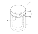
以下、本発明の一実施形態に係る布帛用収容体1を図1から図3に基づいて説明する。図1に示す如く、布帛用収容体1は、携帯型の容器2と、布帛3に覆われた状態で容器2に挿入可能な柱状の挿入部材4と、を備える。
Hereinafter, the fabric container 1 according to the embodiment of the present invention will be described with reference to FIGS. 1 to 3. As shown in FIG. 1, the cloth container 1 includes a
容器2は、一方が開口する円筒状の本体部2aと、本体部2aの開口部を閉塞可能な蓋部2bとで構成される。図2に示す如く、本体部2aは断熱構造であるステンレス真空二重構造で形成された断熱容器である。なお、容器2として、断熱構造を有しない通常の構成を採用することも可能である。また、本体部2aにおける断熱構造として、ガラス真空二重構造又は中空構造を採用することも可能である。但し、断熱効果、強度、意匠性という点で、本実施形態の如くステンレス真空二重構造を採用することが最も好適である。また、二重構造で形成した容器の内部(二重の側板及び底板の間)に、発泡樹脂又は不織布で構成した断熱材を収容した断熱構造を採用することも可能である。
The
容器2は、携帯性及び収納性という観点より、体積が260cm3から540cm3で形成されることが望ましい。特に、携帯しやすさという観点より、高さを12cm〜21cm、半径を3.5cm〜7cmとして円筒形に形成することが望ましい。容器2の蓋部2bには吊り下げ部を形成しても良い。これにより、吊り下げ部を介して布帛用収容体1を衣服やバッグに吊り下げられる他、布帛用収容体1の使用者が吊り下げ部を把持することが可能となる。容器2の蓋部2bについても、断熱性の確保という観点より、空気断熱又は真空断熱を用いた断熱構造、又は、断熱材を用いた断熱構造で構成することが好ましい。
図2及び図3に示す如く、挿入部材4は、柔軟性を有する冷却材である芯材41と、芯材41を内包する芯材ケース42と、で構成される。収納性と冷却効果、流通性という点で、挿入部材4の体積は40cm3から150cm3で形成されることが望ましい。
As shown in FIGS. 2 and 3, the
本実施形態に係る芯材41は、保冷剤、ペルチェ素子、吸熱反応を生じさせるための硝酸アンモニウム、ドライアイス、液体窒素等を採用することができる。また、芯材41に保冷剤を採用する場合は、高吸水性ポリマー、増粘多糖類、CMC、RO水等を用いることが可能である。この際、保冷時間と価格の点で、高吸水性ポリマーを保冷剤として採用することが望ましい。保冷剤には、0℃で凍る冷凍ゲルタイプ、0℃で凍らない不凍ゲルタイプ、0℃でシャーベット状になるシャーベットタイプがあるが、冷却性能と低価格という点で冷凍ゲルタイプが望ましい。
As the
本実施形態において、芯材41は保冷剤が収容された矩形の袋が屈曲されて用いられる。保冷剤を収容する袋の寸法は、縦5cm〜10cm、横10cm〜12cmが望ましい。
In the present embodiment, the
図3に示す如く、本実施形態において芯材ケース42の外形は、容器2の本体部2aの内形状よりも軸方向長さの短い円筒形状に形成される。なお、芯材ケース42の形状は芯材41を内方できるものであれば何でもよく、円筒形状の他に、球状、角柱状等の形状を採用することも可能である。芯材ケース42の体積は、容器2への収納性という観点で、容器2の収納部体積に対して1/10〜1/3とすることが望ましい。
As shown in FIG. 3, in the present embodiment, the outer shape of the
芯材ケース42の材質は、シリコーンエラストマー、アクリル系エラストマー、オレフィン系エラストマー、ポリプロピレン、ポリエチレン、ポリスチレン、ポリカーボネート、ポリアセタール等が採用される。芯材ケース42としては、芯材41との密着性を高めるために、弾性素材を採用することが好ましい。芯材ケース42は、低温性能、耐衝撃性、人体安全性、耐熱性、低コストという理由でシリコーンエラストマーを採用することが最も望ましい。また、芯材ケース42は、冷却性能を維持するため、厚みを0.5mm〜3mmで形成することが好ましい。
As the material of the
図3に示す如く、芯材ケース42の上端面には、芯材41を挿入するための挿入孔が形成されている。挿入孔は、芯材ケース42の上端面の中央部に開口された円形の孔部43aと、孔部43aから互いに反対側に延びる二本の挿入溝43bとで形成される。芯材ケース42は弾性部材で形成されているため、図3中の仮想線に示す如く、挿入溝43bを広げて挿入孔を大きくすることにより、芯材41を芯材ケース42の内部に挿入することができる。本実施形態においては、図3に示す如く挿入孔の形状を芯材41の断面形状よりも小さくすることにより、芯材41が芯材ケース42から抜け出ることを防止している。また、芯材ケース42は、下端面に空気孔を形成することも可能である。この空気孔を介して芯材ケース42に空気が流入、又は、芯材ケース42から空気が流出するため、芯材ケース42に芯材41を出し入れし易くすることができる。
As shown in FIG. 3, an insertion hole for inserting the
本実施形態に係る布帛用収容体1においては図1から図3に示す如く、布帛3は挿入部材4の側面に巻き付けた状態で容器2に収容される。即ち、挿入部材4は、布帛3に覆われた状態で容器2に挿入される。布帛3を構成する生地は木綿、紙等の天然繊維、又は、ポリエステル等の化学繊維を採用することができる。布帛3はおしぼりとして地肌に触れて使用されることが多いため、安全性という点で天然繊維を採用することが望ましい。
In the cloth container 1 according to the present embodiment, as shown in FIGS. 1 to 3, the
布帛3としては、タオル、ハンカチ、ウエス等が採用される。布帛3として使い捨てのウェットティッシュや不織布を採用することも可能である。冷却効果と吸水性という観点からは、布帛3として木綿タオルを採用することが望ましい。布帛3のサイズは、容器2における収納性、顔面を覆う範囲、流通性という理由で縦19cm〜36cm、横19cm〜36cmに形成された矩形のハンドタオルを採用することが望ましい。
As the
布帛用収容体1を使用する際に、布帛3は吸水状態と乾燥状態とのうちどちらで使用しても良いが、冷感効果を高めるためには吸水状態で使用することが望ましい。布帛3を織物で構成する場合、その織り方は平織り、綾織、朱子織、ジャカード織、パイル織、模紗織、クロス織、ワッフル織、リブ織等何でも良い。吸水性と肌触りの観点からは、布帛3をパイル織またはワッフル織で構成することが望ましい。
When the cloth container 1 is used, the
上記の如く、本実施形態に係る布帛用収容体1は、冷却材である芯材41を備えた挿入部材4を布帛3で覆った状態で容器2に収容している。このため、布帛用収容体1においては布帛3を低温で維持することができる。即ち、布帛用収容体1を炎天下で使用した場合でも、布帛3の保冷効果を持続させることが可能となる。
As described above, the cloth container 1 according to the present embodiment is housed in the
また、本実施形態に係る布帛用収容体1によれば、挿入部材4を、柔軟性を有する芯材41と、芯材41を内包する芯材ケース42と、で構成している。このため、本実施形態の如く柔軟性を有する素材で芯材41を構成した場合でも、芯材ケース42により、挿入部材4の形状を円筒形状に保持することが可能となる。これにより、挿入部材4に布帛3を巻きつけた際に、挿入部材4と布帛3との間に空気層を生じ難くすることができるため、冷却効率の低下を抑制できる。即ち、容器2の内部に空気層を生じ難くして、冷却効率を向上させることが可能となる。
Further, according to the fabric accommodating body 1 according to the present embodiment, the
また、布帛用収容体1によれば、芯材ケース42を弾性素材で形成しているため、芯材41を内包した際に芯材ケース42が伸びて薄肉となり、表面冷却効果を向上させることができる。さらに、芯材41が膨張した場合には、芯材ケース42が芯材41の形状変化に追従するため、空気層を小さくして表面冷却効果を向上させることができる。また、芯材ケース42に衝撃吸収力を持たせることが可能となり、芯材41が破れることを防止できる。
Further, according to the fabric container 1, since the
本実施形態において、布帛3は使用後に容器2に入れる事で再度冷却される。このように、本実施形態に係る布帛用収容体1においては、容器2によって、冷却剤の冷却効果を長時間維持する構成としている。
In the present embodiment, the
また、布帛3は挿入部材4の外側面のみを覆った状態で容器2に収容されている。このため、布帛3を容器2から取り出す際に、挿入部材4を容器2に留めさせて、布帛3のみを取り出すことができる。このため、布帛3を容器2に収容する際は、図2に示す如く布帛3の上端部が挿入部材4よりも高く位置することが好ましい。
Further, the
なお、挿入部材4の底面を、容器2の内周底面における中央部に着脱可能に構成することも可能である。これにより、布帛3を容器2から取り出す際に、挿入部材4を容器2に留めさせて、布帛3のみを取り出すことができる。
The bottom surface of the
本実施形態において、芯材41は布帛3を冷却するための構成とされているが、芯材41として柔軟性を有する発熱材を用いることにより、布帛3を温める構成とすることも可能である。即ち、芯材41を酸化鉄、アルミ+酸化カルシウム、ペルチェ素子、ゲル化剤等、熱を発生させる構成とすることにより、布帛用収容体1において布帛3を高い温度(50度から70度程度)で維持することができる。即ち、布帛用収容体1を寒冷な状況で使用した場合でも、布帛3の保温効果を持続させることが可能となる。
In the present embodiment, the
このように、本実施形態に係る布帛用収容体1は、冷却材又は発熱材である芯材41を備える挿入部材4を容器2の内部に収容して、容器2において温度を維持する機能を高める構成としている。これにより、保冷状態又は保温状態の布帛3で挿入部材4を覆って容器2に収容した場合に、布帛3の保冷/保温効果を持続させることができる。また、布帛用収容体1においては、布帛3を挿入部材4に巻き付けた状態で容器2に収容して取り出しやすくすることにより、布帛3をすぐに使用可能とすることができる。
As described above, the fabric container 1 according to the present embodiment has a function of accommodating the
1 布帛用収容体 2 容器
2a 本体部 2b 蓋部
3 タオル(布帛) 4 挿入部材
41 芯材 42 芯材ケース
43a 孔部 43b 挿入溝
1
3 Towel (fabric) 4 Insert member
41
Claims (8)
前記挿入部材は、柔軟性を有する冷却材又は発熱材である芯材と、前記芯材を内包する芯材ケースと、で構成される、布帛用収容体。 A fabric container comprising a portable container and a columnar insertion member that can be inserted into the container while being covered with the cloth contained in the container.
The insertion member is a fabric accommodating body composed of a core material which is a flexible coolant or an exothermic material and a core material case containing the core material.
The cloth container according to any one of claims 1 to 7, wherein the cloth is housed in the container while covering only the outer surface of the insertion member.
Priority Applications (2)
| Application Number | Priority Date | Filing Date | Title |
|---|---|---|---|
| JP2019073917A JP7259500B2 (en) | 2019-04-09 | 2019-04-09 | container for cloth |
| JP2023060807A JP2023083328A (en) | 2019-04-09 | 2023-04-04 | Fabric storing body |
Applications Claiming Priority (1)
| Application Number | Priority Date | Filing Date | Title |
|---|---|---|---|
| JP2019073917A JP7259500B2 (en) | 2019-04-09 | 2019-04-09 | container for cloth |
Related Child Applications (1)
| Application Number | Title | Priority Date | Filing Date |
|---|---|---|---|
| JP2023060807A Division JP2023083328A (en) | 2019-04-09 | 2023-04-04 | Fabric storing body |
Publications (2)
| Publication Number | Publication Date |
|---|---|
| JP2020171402A true JP2020171402A (en) | 2020-10-22 |
| JP7259500B2 JP7259500B2 (en) | 2023-04-18 |
Family
ID=72830464
Family Applications (2)
| Application Number | Title | Priority Date | Filing Date |
|---|---|---|---|
| JP2019073917A Active JP7259500B2 (en) | 2019-04-09 | 2019-04-09 | container for cloth |
| JP2023060807A Pending JP2023083328A (en) | 2019-04-09 | 2023-04-04 | Fabric storing body |
Family Applications After (1)
| Application Number | Title | Priority Date | Filing Date |
|---|---|---|---|
| JP2023060807A Pending JP2023083328A (en) | 2019-04-09 | 2023-04-04 | Fabric storing body |
Country Status (1)
| Country | Link |
|---|---|
| JP (2) | JP7259500B2 (en) |
Cited By (1)
| Publication number | Priority date | Publication date | Assignee | Title |
|---|---|---|---|---|
| JP2023083328A (en) * | 2019-04-09 | 2023-06-15 | スターライト工業株式会社 | Fabric storing body |
Citations (7)
| Publication number | Priority date | Publication date | Assignee | Title |
|---|---|---|---|---|
| US5076424A (en) * | 1988-10-15 | 1991-12-31 | Kennak U.S.A. Inc. | Dispenser container for wet tissues, and a process for manufacturing the same and an apparatus thereof |
| JPH0417114Y2 (en) * | 1988-10-17 | 1992-04-16 | ||
| JPH0675291U (en) * | 1992-02-18 | 1994-10-25 | 高砂香料工業株式会社 | Portable hand towel warmer |
| JP2000333871A (en) * | 1999-05-31 | 2000-12-05 | Pigeon Corp | Heating device and wet tissue container |
| JP2004101064A (en) * | 2002-09-09 | 2004-04-02 | Eight:Kk | ice pack |
| JP3141805U (en) * | 2007-11-12 | 2008-05-22 | さなえ 秋山 | Mobile tissue warm & cool multi-case |
| JP3220974U (en) * | 2019-02-04 | 2019-04-18 | スターライト工業株式会社 | Fabric container |
Family Cites Families (1)
| Publication number | Priority date | Publication date | Assignee | Title |
|---|---|---|---|---|
| JP7259500B2 (en) * | 2019-04-09 | 2023-04-18 | スターライト工業株式会社 | container for cloth |
-
2019
- 2019-04-09 JP JP2019073917A patent/JP7259500B2/en active Active
-
2023
- 2023-04-04 JP JP2023060807A patent/JP2023083328A/en active Pending
Patent Citations (7)
| Publication number | Priority date | Publication date | Assignee | Title |
|---|---|---|---|---|
| US5076424A (en) * | 1988-10-15 | 1991-12-31 | Kennak U.S.A. Inc. | Dispenser container for wet tissues, and a process for manufacturing the same and an apparatus thereof |
| JPH0417114Y2 (en) * | 1988-10-17 | 1992-04-16 | ||
| JPH0675291U (en) * | 1992-02-18 | 1994-10-25 | 高砂香料工業株式会社 | Portable hand towel warmer |
| JP2000333871A (en) * | 1999-05-31 | 2000-12-05 | Pigeon Corp | Heating device and wet tissue container |
| JP2004101064A (en) * | 2002-09-09 | 2004-04-02 | Eight:Kk | ice pack |
| JP3141805U (en) * | 2007-11-12 | 2008-05-22 | さなえ 秋山 | Mobile tissue warm & cool multi-case |
| JP3220974U (en) * | 2019-02-04 | 2019-04-18 | スターライト工業株式会社 | Fabric container |
Cited By (1)
| Publication number | Priority date | Publication date | Assignee | Title |
|---|---|---|---|---|
| JP2023083328A (en) * | 2019-04-09 | 2023-06-15 | スターライト工業株式会社 | Fabric storing body |
Also Published As
| Publication number | Publication date |
|---|---|
| JP2023083328A (en) | 2023-06-15 |
| JP7259500B2 (en) | 2023-04-18 |
Similar Documents
| Publication | Publication Date | Title |
|---|---|---|
| US20110029051A1 (en) | Upper body thermal relief apparatus and method | |
| KR20140141161A (en) | ice neck band using phase change materials | |
| US20040122495A1 (en) | ICE Power Pack | |
| WO1999038469A1 (en) | Hot or cold applicator with inner element | |
| EP2204150A1 (en) | Long-acting cold structure | |
| KR101892657B1 (en) | PCM package for wearing | |
| JP2023083328A (en) | Fabric storing body | |
| US20100125317A1 (en) | Long-Action Cold Pack Structure | |
| JP3220974U (en) | Fabric container | |
| KR20160026273A (en) | portable cooling pack using phange change materials | |
| JP2009185420A (en) | Cooling tool | |
| KR102673904B1 (en) | Neckband with reinforcement frame | |
| JP5808274B2 (en) | Cold insulation used on the neck of a person | |
| JP2004283451A (en) | Eye mask | |
| JP2023155105A (en) | Head cooling device and method for manufacturing the head cooling device | |
| JP3208980U (en) | Head cooling tool | |
| JP6654313B2 (en) | Head cooling tool | |
| KR20240140760A (en) | Multipurpose case | |
| CN214259946U (en) | Novel massage equipment | |
| JP3177696U (en) | Cooling band | |
| JP3033348U (en) | Temperature control container for portable cold storage / heat storage material | |
| JPH09220250A (en) | Cooling band | |
| JP2558534Y2 (en) | Massage pack | |
| KR20140057969A (en) | Cold and warmth mat | |
| CN213883767U (en) | Device for preventing low-temperature frostbite |
Legal Events
| Date | Code | Title | Description |
|---|---|---|---|
| A80 | Written request to apply exceptions to lack of novelty of invention |
Free format text: JAPANESE INTERMEDIATE CODE: A80 Effective date: 20190426 |
|
| A621 | Written request for application examination |
Free format text: JAPANESE INTERMEDIATE CODE: A621 Effective date: 20211021 |
|
| A977 | Report on retrieval |
Free format text: JAPANESE INTERMEDIATE CODE: A971007 Effective date: 20220817 |
|
| A131 | Notification of reasons for refusal |
Free format text: JAPANESE INTERMEDIATE CODE: A131 Effective date: 20220823 |
|
| A601 | Written request for extension of time |
Free format text: JAPANESE INTERMEDIATE CODE: A601 Effective date: 20221019 |
|
| A521 | Request for written amendment filed |
Free format text: JAPANESE INTERMEDIATE CODE: A523 Effective date: 20221219 |
|
| TRDD | Decision of grant or rejection written | ||
| A01 | Written decision to grant a patent or to grant a registration (utility model) |
Free format text: JAPANESE INTERMEDIATE CODE: A01 Effective date: 20230307 |
|
| A61 | First payment of annual fees (during grant procedure) |
Free format text: JAPANESE INTERMEDIATE CODE: A61 Effective date: 20230320 |
|
| R150 | Certificate of patent or registration of utility model |
Ref document number: 7259500 Country of ref document: JP Free format text: JAPANESE INTERMEDIATE CODE: R150 |
|
| R250 | Receipt of annual fees |
Free format text: JAPANESE INTERMEDIATE CODE: R250 |