JP2020174530A - Effective Battery Cell Balancing Methods and Systems Using Duty Control - Google Patents
Effective Battery Cell Balancing Methods and Systems Using Duty Control Download PDFInfo
- Publication number
- JP2020174530A JP2020174530A JP2020117776A JP2020117776A JP2020174530A JP 2020174530 A JP2020174530 A JP 2020174530A JP 2020117776 A JP2020117776 A JP 2020117776A JP 2020117776 A JP2020117776 A JP 2020117776A JP 2020174530 A JP2020174530 A JP 2020174530A
- Authority
- JP
- Japan
- Prior art keywords
- cell balancing
- cell
- battery
- duty ratio
- field effect
- Prior art date
- Legal status (The legal status is an assumption and is not a legal conclusion. Google has not performed a legal analysis and makes no representation as to the accuracy of the status listed.)
- Granted
Links
Images


Classifications
-
- H—ELECTRICITY
- H01—ELECTRIC ELEMENTS
- H01M—PROCESSES OR MEANS, e.g. BATTERIES, FOR THE DIRECT CONVERSION OF CHEMICAL ENERGY INTO ELECTRICAL ENERGY
- H01M10/00—Secondary cells; Manufacture thereof
- H01M10/42—Methods or arrangements for servicing or maintenance of secondary cells or secondary half-cells
- H01M10/4207—Methods or arrangements for servicing or maintenance of secondary cells or secondary half-cells for several batteries or cells simultaneously or sequentially
-
- H—ELECTRICITY
- H02—GENERATION; CONVERSION OR DISTRIBUTION OF ELECTRIC POWER
- H02J—ELECTRIC POWER NETWORKS; CIRCUIT ARRANGEMENTS OR SYSTEMS FOR SUPPLYING OR DISTRIBUTING ELECTRIC POWER; SYSTEMS FOR STORING ELECTRIC ENERGY
- H02J7/00—Circuit arrangements for charging or discharging batteries or for supplying loads from batteries
- H02J7/50—Circuit arrangements for charging or discharging batteries or for supplying loads from batteries acting upon multiple batteries simultaneously or sequentially
- H02J7/52—Circuit arrangements for charging or discharging batteries or for supplying loads from batteries acting upon multiple batteries simultaneously or sequentially for charge balancing, e.g. equalisation of charge between batteries
- H02J7/54—Passive balancing, e.g. using resistors or parallel MOSFETs
-
- G—PHYSICS
- G01—MEASURING; TESTING
- G01R—MEASURING ELECTRIC VARIABLES; MEASURING MAGNETIC VARIABLES
- G01R31/00—Arrangements for testing electric properties; Arrangements for locating electric faults; Arrangements for electrical testing characterised by what is being tested not provided for elsewhere
- G01R31/36—Arrangements for testing, measuring or monitoring the electrical condition of accumulators or electric batteries, e.g. capacity or state of charge [SoC]
-
- G—PHYSICS
- G01—MEASURING; TESTING
- G01R—MEASURING ELECTRIC VARIABLES; MEASURING MAGNETIC VARIABLES
- G01R31/00—Arrangements for testing electric properties; Arrangements for locating electric faults; Arrangements for electrical testing characterised by what is being tested not provided for elsewhere
- G01R31/36—Arrangements for testing, measuring or monitoring the electrical condition of accumulators or electric batteries, e.g. capacity or state of charge [SoC]
- G01R31/382—Arrangements for monitoring battery or accumulator variables, e.g. SoC
-
- H—ELECTRICITY
- H01—ELECTRIC ELEMENTS
- H01M—PROCESSES OR MEANS, e.g. BATTERIES, FOR THE DIRECT CONVERSION OF CHEMICAL ENERGY INTO ELECTRICAL ENERGY
- H01M10/00—Secondary cells; Manufacture thereof
- H01M10/42—Methods or arrangements for servicing or maintenance of secondary cells or secondary half-cells
-
- H—ELECTRICITY
- H01—ELECTRIC ELEMENTS
- H01M—PROCESSES OR MEANS, e.g. BATTERIES, FOR THE DIRECT CONVERSION OF CHEMICAL ENERGY INTO ELECTRICAL ENERGY
- H01M10/00—Secondary cells; Manufacture thereof
- H01M10/42—Methods or arrangements for servicing or maintenance of secondary cells or secondary half-cells
- H01M10/425—Structural combination with electronic components, e.g. electronic circuits integrated to the outside of the casing
-
- H—ELECTRICITY
- H01—ELECTRIC ELEMENTS
- H01M—PROCESSES OR MEANS, e.g. BATTERIES, FOR THE DIRECT CONVERSION OF CHEMICAL ENERGY INTO ELECTRICAL ENERGY
- H01M10/00—Secondary cells; Manufacture thereof
- H01M10/42—Methods or arrangements for servicing or maintenance of secondary cells or secondary half-cells
- H01M10/48—Accumulators combined with arrangements for measuring, testing or indicating the condition of cells, e.g. the level or density of the electrolyte
-
- H—ELECTRICITY
- H01—ELECTRIC ELEMENTS
- H01M—PROCESSES OR MEANS, e.g. BATTERIES, FOR THE DIRECT CONVERSION OF CHEMICAL ENERGY INTO ELECTRICAL ENERGY
- H01M10/00—Secondary cells; Manufacture thereof
- H01M10/42—Methods or arrangements for servicing or maintenance of secondary cells or secondary half-cells
- H01M10/48—Accumulators combined with arrangements for measuring, testing or indicating the condition of cells, e.g. the level or density of the electrolyte
- H01M10/486—Accumulators combined with arrangements for measuring, testing or indicating the condition of cells, e.g. the level or density of the electrolyte for measuring temperature
-
- H—ELECTRICITY
- H01—ELECTRIC ELEMENTS
- H01M—PROCESSES OR MEANS, e.g. BATTERIES, FOR THE DIRECT CONVERSION OF CHEMICAL ENERGY INTO ELECTRICAL ENERGY
- H01M50/00—Constructional details or processes of manufacture of the non-active parts of electrochemical cells other than fuel cells, e.g. hybrid cells
- H01M50/20—Mountings; Secondary casings or frames; Racks, modules or packs; Suspension devices; Shock absorbers; Transport or carrying devices; Holders
- H01M50/204—Racks, modules or packs for multiple batteries or multiple cells
-
- H—ELECTRICITY
- H02—GENERATION; CONVERSION OR DISTRIBUTION OF ELECTRIC POWER
- H02J—ELECTRIC POWER NETWORKS; CIRCUIT ARRANGEMENTS OR SYSTEMS FOR SUPPLYING OR DISTRIBUTING ELECTRIC POWER; SYSTEMS FOR STORING ELECTRIC ENERGY
- H02J7/00—Circuit arrangements for charging or discharging batteries or for supplying loads from batteries
- H02J7/90—Regulation of charging or discharging current or voltage
- H02J7/971—Regulation of charging or discharging current or voltage the charge cycle being controlled or terminated in response to non-electric parameters
- H02J7/975—Regulation of charging or discharging current or voltage the charge cycle being controlled or terminated in response to non-electric parameters in response to temperature
- H02J7/977—Regulation of charging or discharging current or voltage the charge cycle being controlled or terminated in response to non-electric parameters in response to temperature of the battery
-
- H—ELECTRICITY
- H01—ELECTRIC ELEMENTS
- H01M—PROCESSES OR MEANS, e.g. BATTERIES, FOR THE DIRECT CONVERSION OF CHEMICAL ENERGY INTO ELECTRICAL ENERGY
- H01M10/00—Secondary cells; Manufacture thereof
- H01M10/42—Methods or arrangements for servicing or maintenance of secondary cells or secondary half-cells
- H01M10/425—Structural combination with electronic components, e.g. electronic circuits integrated to the outside of the casing
- H01M2010/4271—Battery management systems including electronic circuits, e.g. control of current or voltage to keep battery in healthy state, cell balancing
-
- Y—GENERAL TAGGING OF NEW TECHNOLOGICAL DEVELOPMENTS; GENERAL TAGGING OF CROSS-SECTIONAL TECHNOLOGIES SPANNING OVER SEVERAL SECTIONS OF THE IPC; TECHNICAL SUBJECTS COVERED BY FORMER USPC CROSS-REFERENCE ART COLLECTIONS [XRACs] AND DIGESTS
- Y02—TECHNOLOGIES OR APPLICATIONS FOR MITIGATION OR ADAPTATION AGAINST CLIMATE CHANGE
- Y02E—REDUCTION OF GREENHOUSE GAS [GHG] EMISSIONS, RELATED TO ENERGY GENERATION, TRANSMISSION OR DISTRIBUTION
- Y02E60/00—Enabling technologies; Technologies with a potential or indirect contribution to GHG emissions mitigation
- Y02E60/10—Energy storage using batteries
-
- Y—GENERAL TAGGING OF NEW TECHNOLOGICAL DEVELOPMENTS; GENERAL TAGGING OF CROSS-SECTIONAL TECHNOLOGIES SPANNING OVER SEVERAL SECTIONS OF THE IPC; TECHNICAL SUBJECTS COVERED BY FORMER USPC CROSS-REFERENCE ART COLLECTIONS [XRACs] AND DIGESTS
- Y02—TECHNOLOGIES OR APPLICATIONS FOR MITIGATION OR ADAPTATION AGAINST CLIMATE CHANGE
- Y02T—CLIMATE CHANGE MITIGATION TECHNOLOGIES RELATED TO TRANSPORTATION
- Y02T10/00—Road transport of goods or passengers
- Y02T10/60—Other road transportation technologies with climate change mitigation effect
- Y02T10/70—Energy storage systems for electromobility, e.g. batteries
Landscapes
- Engineering & Computer Science (AREA)
- General Chemical & Material Sciences (AREA)
- Chemical & Material Sciences (AREA)
- Chemical Kinetics & Catalysis (AREA)
- Electrochemistry (AREA)
- Manufacturing & Machinery (AREA)
- Power Engineering (AREA)
- Physics & Mathematics (AREA)
- General Physics & Mathematics (AREA)
- Microelectronics & Electronic Packaging (AREA)
- Charge And Discharge Circuits For Batteries Or The Like (AREA)
- Secondary Cells (AREA)
- Tests Of Electric Status Of Batteries (AREA)
Abstract
【課題】本発明は、デューティ比制御を用いたバッテリセルバランシングに係る。【解決手段】本発明は、更に詳しくは、バッテリセルバランシングの際に前記セルに流れる電流によって発生する抵抗の温度を検出して、これに伴うセルバランシングのデューティ比を算出し、前記セルバランシング動作の開始から所定の時間が経過後にバッテリセルの電圧を検出することにより、正確性及び効率性が向上したバッテリセルバランシングの方法及びシステムに関する。【選択図】図2PROBLEM TO BE SOLVED: To provide battery cell balancing using duty ratio control. More specifically, the present invention detects the temperature of a resistor generated by a current flowing through the cell during battery cell balancing, calculates the duty ratio of the cell balancing associated therewith, and performs the cell balancing operation. The present invention relates to a battery cell balancing method and system in which accuracy and efficiency are improved by detecting the voltage of the battery cell after a lapse of a predetermined time from the start of the above. [Selection diagram] Fig. 2
Description
本発明は、デューティ比制御を用いたバッテリセルバランシングに係り、更に詳しくは、バッテリセルバランシングの際に前記セルに流れる電流によって発生する抵抗の温度を検出して、これに伴うセルバランシングのデューティ比を算出し、前記セルバランシング動作の開始から所定の時間が経過後にバッテリセルの電圧を検出することにより、正確性及び効率性が向上したバッテリセルバランシングの方法及びシステムに関する。 The present invention relates to battery cell balancing using duty ratio control, and more specifically, detects the temperature of a resistor generated by a current flowing through the cell during battery cell balancing, and the duty ratio of cell balancing associated therewith is detected. The present invention relates to a battery cell balancing method and system in which accuracy and efficiency are improved by calculating the voltage of the battery cell after a predetermined time has elapsed from the start of the cell balancing operation.
一般に、エネルギー蓄積装置、電気自動車、携帯用電子機器などの充電可能な電気貯蔵装置を必要とする装置に搭載されるバッテリパックは、直列又は並列に接続された多数のバッテリセルを備える。前記多数のバッテリセルが組み込まれているバッテリパックを放電すれば、各セルの自己放電率の違いによって、時間の経過に伴い前記各セルの充電状態の違いが生じる。このような充電状態のバラツキがある状態でバッテリパックの放電が行われ続ければ、充電状態が低い特定のセルが過放電されて前記バッテリパックの安定的な動作が行われ難くなる。なお、充電過程において特定のバッテリセルが過充電される場合も同様に、バッテリパックの安定的な動作を妨げる要因である。 Generally, a battery pack mounted on a device that requires a rechargeable electric storage device such as an energy storage device, an electric vehicle, or a portable electronic device includes a large number of battery cells connected in series or in parallel. When the battery pack incorporating the large number of battery cells is discharged, the charge state of each cell changes with the passage of time due to the difference in the self-discharge rate of each cell. If the battery pack continues to be discharged in such a state of variation in the charging state, a specific cell having a low charging state is over-discharged, and it becomes difficult to perform stable operation of the battery pack. Similarly, when a specific battery cell is overcharged in the charging process, it is a factor that hinders the stable operation of the battery pack.
このようにして発生する特定のバッテリセルの過充電又は過放電は、バッテリパックの容量を減らすだけではなく、前記バッテリパックを劣化させ、しかも、寿命を短縮させるという問題を引き起こす虞がある。 Overcharging or overdischarging of a specific battery cell thus generated may cause a problem that not only the capacity of the battery pack is reduced, but also the battery pack is deteriorated and the life is shortened.
したがって、バッテリパックを効率よく管理するための方法であって、前記バッテリパックを構成するバッテリセルのそれぞれの電圧差が所定の許容範囲内に収まるように、或いは、それに等しくなるように調節するバッテリセルのバランシングは必ず行われなければならない。 Therefore, it is a method for efficiently managing the battery pack, and the battery is adjusted so that the voltage difference between the battery cells constituting the battery pack is within a predetermined allowable range or is equal to the voltage difference. Cell balancing must always be done.
従来には、バッテリセルの充電状態に対する前記バッテリセルの開放電圧の変化が基準値以上であるか、或いは、基準値以下である場合、バランシングの対象となるセルを選択して所定の時間の間にバランシング動作を行う方法、バッテリセルのバランシング制御動作の間にリアルタイムにて各バッテリセルの電圧をモニタリングして前記バランシング動作の完了の有無を判断する方法、又はバッテリセルのそれぞれの電圧を測定し、前記測定された電圧のうちのいずれか1つをバランシング基準電圧に設定して基準電圧に従う充放電を通じてバランシングを行う方法などを用いてバッテリセル間のバランシングを行っていた。 Conventionally, when the change of the open circuit voltage of the battery cell with respect to the charged state of the battery cell is equal to or more than the reference value or equal to or less than the reference value, the cell to be balanced is selected and for a predetermined time. A method of performing a balancing operation, a method of monitoring the voltage of each battery cell in real time during a battery cell balancing control operation to determine whether or not the balancing operation is completed, or a method of measuring the voltage of each battery cell. , Any one of the measured voltages is set as the balancing reference voltage, and balancing is performed through charging / discharging according to the reference voltage to perform balancing between battery cells.
しかしながら、上記の従来の方法は、バッテリセルバランシング中に流れる持続的な電流による抵抗の発熱問題が存在し、前記バッテリセルバランシングの開始から電圧検出時点までの所要時間がセルバランシングの際に流れる電流の大きさを問わずに一定しているため、前記バッテリセルバランシングの正確性及び効率性が低下するという問題がある。 However, the above-mentioned conventional method has a problem of heat generation of resistance due to a continuous current flowing during battery cell balancing, and the time required from the start of battery cell balancing to the time of voltage detection is the current flowing during cell balancing. Since it is constant regardless of the size of the battery cell, there is a problem that the accuracy and efficiency of the battery cell balancing are lowered.
本発明は、上述した問題を解消するために案出されたものであり、セルバランシングの際に流れる電流によって抵抗に発生する発熱問題を極力抑え、前記セルバランシングの開始から電圧検出時点までの時間を制御して効率性を向上させるバッテリのセルバランシング方法を提供することを目的とする。 The present invention has been devised to solve the above-mentioned problems, and suppresses the heat generation problem generated in the resistor due to the current flowing during cell balancing as much as possible, and the time from the start of the cell balancing to the time of voltage detection. It is an object of the present invention to provide a cell balancing method for a battery that controls and improves efficiency.
本発明の目的を達成するためのバッテリセルのバランシングシステムは、2つ以上のバッテリセルを備えてなるバッテリパックと、前記バッテリセルバランシングを制御するバッテリ管理部と、を備えてなり、前記バッテリ管理部は、バッテリセルのバランシング動作条件の充足の有無を判断し、その判断結果に基づいて、セルバランシング制御電界効果トランジスタ(FET)にオン/オフ信号を印加してセルバランシング動作を制御するセルバランシング動作制御部と、セルバランシング動作が行われる間にセルバランシング電流の大きさを測定するセルバランシング電流算出部と、セルバランシング動作が行われる間に流れる前記セルバランシング電流によって発生するセルバランシング抵抗の温度を算出するセルバランシング抵抗温度算出部と、前記算出されたセルバランシング抵抗の温度値に応じたセルバランシング制御電界効果トランジスタ(FET)のオン/オフ周期に対するデューティ比を算出するデューティ比算出部と、前記バッテリセルの電圧を検出する電圧検出部と、を備えてなる。 The battery cell balancing system for achieving the object of the present invention comprises a battery pack including two or more battery cells and a battery management unit for controlling the battery cell balancing, and the battery management. The unit determines whether or not the balancing operation conditions of the battery cell are satisfied, and based on the determination result, applies an on / off signal to the cell balancing control field effect transistor (FET) to control the cell balancing operation. The temperature of the cell balancing resistance generated by the operation control unit, the cell balancing current calculation unit that measures the magnitude of the cell balancing current during the cell balancing operation, and the cell balancing current that flows during the cell balancing operation. A cell balancing resistance temperature calculation unit for calculating the above, a duty ratio calculation unit for calculating the duty ratio with respect to the on / off period of the cell balancing control field effect transistor (FET) according to the calculated temperature value of the cell balancing resistance. A voltage detection unit for detecting the voltage of the battery cell is provided.
一方、前記デューティ比算出部は、前記セルバランシング抵抗温度算出部において算出された抵抗の温度値が属する温度区間を検出し、前記検出された温度区間に対応するセルバランシング制御電界効果トランジスタ(FET)のオン/オフ信号のデューティ比を算出して、前記セルバランシング動作制御部に与えることを特徴とする。 On the other hand, the duty ratio calculation unit detects the temperature section to which the temperature value of the resistor calculated by the cell balancing resistance temperature calculation unit belongs, and the cell balancing control field effect transistor (FET) corresponding to the detected temperature section. The duty ratio of the on / off signal is calculated and given to the cell balancing operation control unit.
一方、前記電圧検出部は、前記バッテリセルの電圧の偏差を算出し、前記バッテリセルのそれぞれの電圧偏差のうちの少なくとも1つ以上が所定の基準値以上である場合、バッテリセルバランシングを行う必要があると判断して、バランシングを行う必要があるセルを検出するセル検出部と、前記セルバランシング制御電界効果トランジスタ(FET)がターンオフされた後、セルバランシングが適用されたセルの電圧を検出し、所定の基準値と比較してセルバランシングの成否を判断するセルバランシング電圧検出部と、を備えてなることを特徴とする。 On the other hand, the voltage detection unit calculates the voltage deviation of the battery cell, and when at least one or more of the voltage deviations of the battery cells is equal to or more than a predetermined reference value, it is necessary to perform battery cell balancing. The cell detector that detects the cell that needs to be balanced and the cell balancing control field effect transistor (FET) are turned off, and then the voltage of the cell to which cell balancing is applied is detected. It is characterized by including a cell balancing voltage detection unit for determining the success or failure of cell balancing by comparing with a predetermined reference value.
ここで、前記セルバランシング電圧検出部は、前記セルバランシング制御電界効果トランジスタ(FET)がターンオフされた後、所定の時間が経過した後に動作することを特徴とする。 Here, the cell balancing voltage detection unit is characterized in that it operates after a predetermined time has elapsed after the cell balancing control field effect transistor (FET) is turned off.
前記セルバランシング動作制御部は、セルバランシングが始まる段階では、セルバランシング制御電界効果トランジスタ(FET)を所定のデューティ比を有するオン/オフ制御信号で制御し、その後、セルバランシング動作の際に発生する抵抗の温度に応じて算出されたデューティ比でセルバランシング制御電界効果トランジスタ(FET)のオン/オフを制御することを特徴とする。 The cell balancing operation control unit controls the cell balancing control field effect transistor (FET) with an on / off control signal having a predetermined duty ratio at the stage when the cell balancing starts, and then occurs during the cell balancing operation. The cell balancing control field effect transistor (FET) is controlled on / off with a duty ratio calculated according to the temperature of the resistor.
また、本発明の目的を達成するためのバッテリセルのバランシング方法は、バッテリセルのバランシング動作条件の充足の有無を判断し、その判断結果に基づいて、セルバランシング制御電界効果トランジスタ(FET)にオン/オフ信号を印加してセルバランシング動作を制御するセルバランシング動作判断ステップと、セルバランシング動作が行われる間に流れるセルバランシング電流の大きさを測定して算出するセルバランシング電流算出ステップと、セルバランシング動作が行われる間に流れるセルバランシング電流によって発生するセルバランシング抵抗の温度を算出するセルバランシング抵抗温度算出ステップと、前記算出されたセルバランシング抵抗の温度値に応じたセルバランシング制御電界効果トランジスタ(FET)のオン/オフ周期に対するデューティ比を算出するデューティ比算出ステップと、前記算出されたデューティ比に基づいて、セルバランシング制御電界効果トランジスタ(FET)にオン/オフ信号を印加してセルバランシング動作を行うセルバランシング動作ステップと、前記バッテリセルの電圧を検出する電圧検出ステップと、を含んでなる。 Further, in the battery cell balancing method for achieving the object of the present invention, it is determined whether or not the battery cell balancing operating conditions are satisfied, and based on the determination result, the cell balancing control field effect transistor (FET) is turned on. A cell balancing operation judgment step that controls the cell balancing operation by applying a / off signal, a cell balancing current calculation step that measures and calculates the magnitude of the cell balancing current that flows during the cell balancing operation, and cell balancing. A cell balancing resistance temperature calculation step for calculating the temperature of the cell balancing resistance generated by the cell balancing current flowing during the operation, and a cell balancing control field effect transistor (FET) according to the calculated temperature value of the cell balancing resistance. ) To the duty ratio calculation step for calculating the on / off cycle, and the cell balancing operation by applying the on / off signal to the cell balancing control field effect transistor (FET) based on the calculated duty ratio. It includes a cell balancing operation step to be performed and a voltage detection step for detecting the voltage of the battery cell.
一方、前記デューティ比算出ステップにおいては、前記セルバランシング抵抗温度算出ステップにおいて算出された抵抗の温度値が属する温度区間を検出し、前記検出された温度区間に対応するセルバランシング制御電界効果トランジスタ(FET)のオン/オフ信号のデューティ比を算出することを特徴とする。 On the other hand, in the duty ratio calculation step, the temperature section to which the temperature value of the resistor calculated in the cell balancing resistance temperature calculation step belongs is detected, and the cell balancing control field effect transistor (FET) corresponding to the detected temperature section is detected. ) Is characterized in that the duty ratio of the on / off signal is calculated.
一方、前記電圧検出ステップにおいては、前記セルバランシング制御電界効果トランジスタ(FET)がターンオフされた後、所定の時間が経過した後に前記セルバランシングが適用されたセルの電圧を検出し、所定の基準値と比較してセルバランシングの成否を判断することを特徴とする。 On the other hand, in the voltage detection step, the voltage of the cell to which the cell balancing is applied is detected after a predetermined time has elapsed after the cell balancing control field effect transistor (FET) is turned off, and a predetermined reference value is obtained. It is characterized in that the success or failure of cell balancing is judged in comparison with.
一方、前記セルバランシング動作判断ステップにおいては、セルバランシング動作が始まる段階では、セルバランシング制御電界効果トランジスタ(FET)を所定のデューティ比を有するオン/オフ制御信号でオン/オフ制御し、その後、デューティ比算出ステップにおいて算出されるセルバランシング制御電界効果トランジスタ(FET)のオン/オフデューティ比に基づいて、オン/オフ信号を印加することを特徴とする。 On the other hand, in the cell balancing operation determination step, at the stage when the cell balancing operation starts, the cell balancing control field effect transistor (FET) is on / off controlled by an on / off control signal having a predetermined duty ratio, and then the duty is controlled. It is characterized in that an on / off signal is applied based on the on / off duty ratio of the cell balancing control field effect transistor (FET) calculated in the ratio calculation step.
本発明によれば、バッテリのセルバランシング動作の際に流れる電流によって発生する抵抗の温度に応じて算出されたセルバランシングデューティ比を用いてセルバランシングを行い、所定の時間が経過した後に電圧を検出することにより、電圧の測定の正確性を向上させ、前記セルバランシング動作の際に流れる電流によって発生する抵抗の発熱問題を効果的に制御することができて、効率性が向上したバッテリセル間のバランシングが行われる。 According to the present invention, cell balancing is performed using the cell balancing duty ratio calculated according to the temperature of the resistor generated by the current flowing during the cell balancing operation of the battery, and the voltage is detected after a predetermined time has elapsed. By doing so, it is possible to improve the accuracy of voltage measurement, effectively control the heat generation problem of the resistor generated by the current flowing during the cell balancing operation, and improve the efficiency between the battery cells. Balancing is done.
以下、添付図面に基づいて、本発明が属する技術分野において通常の知識を有する者が実施し易いように本発明の実施形態について詳細に説明する。しかしながら、本発明は色々な異なる形態に具体化可能であり、ここで説明する実施形態に何ら限定されない。なお、図中、本発明を明確に説明するために説明とは無関係な部分は省略し、明細書の全般に亘って、類似する部分に対しては類似する図面符号を付している。 Hereinafter, embodiments of the present invention will be described in detail based on the accompanying drawings so as to be easily carried out by a person having ordinary knowledge in the technical field to which the present invention belongs. However, the present invention can be embodied in various different forms and is not limited to the embodiments described herein. In the drawings, parts unrelated to the description are omitted in order to clearly explain the present invention, and similar drawing reference numerals are given to similar parts throughout the specification.
明細書の全般に亘って、ある部分が他の部分と「接続」されているとしたとき、これは、「直結」されている場合だけではなく、これらの間に他の素子を挟んで「電気的に接続」されている場合も含む。なお、ある部分がある構成要素を「備える」としたとき、これは、特に断りのない限り、他の構成要素を排除するものではなく、他の構成要素を更に備え得るということを意味する。本願明細書の全体において用いられる程度の用語「〜するステップ」又は「〜のステップ」は、「〜のためのステップ」を意味しない。 Throughout the specification, when one part is "connected" to another, this is not only when it is "directly connected", but also when another element is sandwiched between them. Including the case where it is "electrically connected". It should be noted that when a certain component is "equipped" with a certain component, this does not exclude other components unless otherwise specified, and means that other components can be further provided. The term "step to" or "step to" as used throughout the specification of the present application does not mean "step to".
本発明によれば、バッテリパックに組み込まれている少なくとも2つ以上のバッテリセルの電圧をバランシングするバッテリセルのバランシング方法は、バッテリセルのバランシング動作条件の充足の有無を判断し、その判断結果に基づいて、セルバランシング制御電界効果トランジスタ(FET)にオン/オフ信号を印加してセルバランシング動作を制御するセルバランシング動作判断ステップと、セルバランシング動作が行われる間に流れるセルバランシング電流の大きさを測定して算出するセルバランシング電流算出ステップと、セルバランシング動作が行われる間に前記セルバランシング電流によって発生するセルバランシング抵抗の温度を算出するセルバランシング抵抗温度算出ステップと、前記算出されたセルバランシング抵抗の温度値に応じたセルバランシング制御電界効果トランジスタ(FET)のオン/オフ周期に対するデューティ比を算出するデューティ比算出ステップと、前記算出されたデューティ比に基づいて、セルバランシング制御電界効果トランジスタ(FET)にオン/オフ信号を印加してセルバランシング動作を行うセルバランシング動作ステップと、前記バッテリセルの電圧を検出する電圧検出ステップと、を含んでなる。 According to the present invention, the battery cell balancing method for balancing the voltages of at least two or more battery cells incorporated in the battery pack determines whether or not the balancing operating conditions of the battery cells are satisfied, and the determination result is used. Based on this, the cell balancing operation judgment step of applying an on / off signal to the cell balancing control field effect transistor (FET) to control the cell balancing operation and the magnitude of the cell balancing current flowing during the cell balancing operation are determined. A cell balancing current calculation step that measures and calculates, a cell balancing resistance temperature calculation step that calculates the temperature of the cell balancing resistance generated by the cell balancing current while the cell balancing operation is performed, and the calculated cell balancing resistance. Cell balancing control field effect transistor (FET) based on the duty ratio calculation step to calculate the duty ratio to the on / off cycle of the cell balancing control field effect transistor (FET) according to the temperature value of ) Includes a cell balancing operation step in which an on / off signal is applied to perform a cell balancing operation, and a voltage detection step in which the voltage of the battery cell is detected.
本発明において言及するデューティ比とは、前記セルバランシング制御電界効果トランジスタ(FET)のオン/オフ信号が印加される時間の比を意味する。 The duty ratio referred to in the present invention means the ratio of the time during which the on / off signal of the cell balancing control field effect transistor (FET) is applied.
詳細な説明に先立って、図1に基づいて本発明の構成について説明する。 Prior to the detailed description, the configuration of the present invention will be described with reference to FIG.
前記図1の回路図を参照すると、Aで示された部分は、本発明において言及されるセルバランシング制御電界効果トランジスタ(FET)である。前記セルバランシング制御電界効果トランジスタ(FET)のオン/オフに応じて、セルバランシングのための電流が流れたり遮断されたりする。 With reference to the circuit diagram of FIG. 1, the portion indicated by A is a cell balancing controlled field effect transistor (FET) referred to in the present invention. Depending on the on / off of the cell balancing control field effect transistor (FET), the current for cell balancing flows or is cut off.
本発明において言及されるセルバランシング電流は、セルバランシング動作が行われる間に流れる電流である。例えば、前記セルバランシング制御電界効果トランジスタ(FET)がターンオンされた後、a−b端子の間に流れる電流を意味する。 The cell balancing current referred to in the present invention is the current that flows during the cell balancing operation. For example, it means the current flowing between the ab terminals after the cell balancing control field effect transistor (FET) is turned on.
また、本発明において言及されるセルバランシング抵抗は、セルバランシング動作が行われる間に前記セルバランシング電流が流れる区間に設けられている抵抗である。例えば、図1のa−b端子の間に設けられているR21及びR20であってもよい。 Further, the cell balancing resistor referred to in the present invention is a resistor provided in a section in which the cell balancing current flows while the cell balancing operation is performed. For example, R21 and R20 provided between the ab terminals in FIG. 1 may be used.
したがって、本発明は、セルバランシング電流によって発生するセルバランシング抵抗の温度に応じて、セルバランシング制御電界効果トランジスタ(FET)のオン/オフ周期を制御することができる。 Therefore, the present invention can control the on / off period of the cell balancing control field effect transistor (FET) according to the temperature of the cell balancing resistor generated by the cell balancing current.
以下、残りの図面に基づいて、本発明について詳細に説明する。 Hereinafter, the present invention will be described in detail with reference to the remaining drawings.
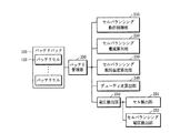
図2は、本発明に係る全体のシステム構成を示すブロック図である。 FIG. 2 is a block diagram showing an overall system configuration according to the present invention.
図2を参照すると、本発明に係るバッテリのセルバランシングのためのシステムは、バッテリパック100と、バッテリ管理部200と、により構成される。
Referring to FIG. 2, the system for cell balancing of the battery according to the present invention includes a
前記バッテリパック100は、直列及び並列に接続されたそれぞれのバッテリセル110を少なくとも2つ以上備えてなることが好ましい。
The
前記バッテリパック100を構成するバッテリセル110のバランシングを制御するバッテリ管理部200は、セルバランシング動作制御部210と、セルバランシング電流算出部220と、セルバランシング抵抗温度算出部230と、デューティ比算出部240及び電圧検出部250を備えてなることが好ましく、前記電圧検出部250は、セル検出部251と、セルバランシング電圧検出部252と、を備えてなることが好ましい。
The
前記セルバランシング動作制御部210は、前記バッテリセル110のバランシング動作条件の充足の有無を判断し、前記判断の結果に基づいて、セルバランシング制御電界効果トランジスタ(FET)にオン/オフ信号を印加してセルバランシング動作を制御してもよい。
The cell balancing
前記セルバランシング動作制御部210は、前記セルバランシング動作が始まる段階でセルバランシング制御電界効果トランジスタ(FET)を所定のデューティ比を有するオン/オフ制御信号でオン/オフ制御し、その後には、前記デューティ比算出部240において算出されたデューティ比に基づいて、セルバランシング制御電界効果トランジスタ(FET)にオン/オフ信号を印加して制御してもよい。
The cell balancing
前記セルバランシングの動作条件の充足の有無の判断に際しては、前記セル検出部251に提供する、バランシングを行う必要があるセルに関する情報を用いて動作有無を判断してもよい。
In determining whether or not the cell balancing operation conditions are satisfied, the presence or absence of operation may be determined using the information provided to the
前記セル検出部251の詳細については、電圧検出部250について説明するときに説明する。
The details of the
また、セルバランシング動作制御部210は、前記セル検出部251が提供する情報に加えて、前記セルバランシング電流算出部220において算出されるセルバランシング動作が行われる間に流れる電流の状態などを含めて、一般的にセルバランシングの動作条件として用いられる各種の要素を含んでなることが好ましい。
Further, the cell balancing
前記セルバランシング電流算出部220は、前記セルバランシング動作が行われる間に流れるセルバランシング電流の大きさを測定して算出してもよい。前記電流の大きさの算出に際しては、一般的に用いられる公式、つまり、電流=電圧/抵抗の公式を用いて算出する方法が採用可能である。
The cell balancing
更に、前記セルバランシング電流算出部220は、セルバランシング動作が行われる間に流れる電流の状態を検出して前記セルバランシング動作制御部210に与えてもよい。
Further, the cell balancing
前記セルバランシング動作が行われる間に流れる電流を算出する方法においては、前記バッテリセル110に直列に接続された電流センシング抵抗を接続して前記セル110の両端の電位差を測定する。前記測定された電位差を用いて前記バッテリセル110の電流が流れる方向を把握して、電流の充電、放電又は電流が流れない状態を検出してもよい。
In the method of calculating the current flowing during the cell balancing operation, a current sensing resistor connected in series with the
前記電流センシング抵抗は、回路の特定の部分にどれ位の電流が流れるかを確認するために用いるものであって、非常に低い抵抗値を有している。前記抵抗値が非常に低いため、電流の流れを大きく妨げず、その結果、より正確に前記バッテリセル110の電流量を測定することができる。
The current sensing resistor is used to check how much current flows through a specific part of the circuit, and has a very low resistance value. Since the resistance value is very low, the current flow is not significantly obstructed, and as a result, the current amount of the
前記セルバランシング抵抗温度算出部230は、前記セルバランシング動作が行われる間に流れる前記セルバランシング電流によって発生するセルバランシング抵抗の温度値を算出してもよい。
The cell balancing resistance
前記セルバランシング抵抗の温度値の算出に際しては、サーミスタ(Themistor)を用いる。アナログ‐デジタル変換気器(ADC)を用いてサーミスタ(Themistor)にかかる電圧を測定し、これを用いて逆に抵抗値を算出して温度値を計算してもよい。 A thermistor is used in calculating the temperature value of the cell balancing resistor. The voltage applied to the thermistor may be measured using an analog-to-digital converter (ADC), and the resistance value may be calculated and the temperature value may be calculated using the voltage.
前記サーミスタ(Themistor)の接続方式としては、ワイヤ方式及びチップ抵抗方式が挙げられ、本発明においては、一般的に、セルバランシング回路を構成する抵抗の周りにチップを設計するチップ抵抗方式を採用してもよい。 Examples of the thermistor connection method include a wire method and a chip resistance method. In the present invention, a chip resistance method in which a chip is designed around a resistor constituting a cell balancing circuit is generally adopted. You may.
前記デューティ比算出部240は、前記セルバランシング抵抗温度算出部230において算出されたセルバランシング抵抗の温度値が属する温度区間を検出し、前記検出された温度区間に対応するセルバランシング制御電界効果トランジスタ(FET)のオン/オフ周期に対するデューティ比を算出してもよく、その例は、下記表の通りである。
The duty
また、前記デューティ比算出部240は、算出されたセルバランシング制御電界効果トランジスタ(FET)のオン/オフに対するデューティ比を前記セルバランシング動作制御部210に与えてもよい。
Further, the duty
前記電圧検出部250は、セル検出部251と、セルバランシング電圧検出部252と、を備えてなることが好ましい。
The
前記セル検出部251は、前記バッテリセル110の電圧の偏差を算出し、前記バッテリセル110のそれぞれの電圧偏差と所定の基準値とを比較して、バランシングを行う必要があるセル110を検出してもよい。算出されたバッテリセルのそれぞれの電圧偏差のうちの少なくとも1つ以上が所定の基準値以上である場合、バッテリセルバランシングを行う必要があると判断して、バランシングを行う必要があるセル110を検出してもよい。なお、検出されたセルに関する情報をセルバランシング動作制御部210に提供してもよい。
The
前記セルバランシング電圧検出部252は、前記セルバランシング制御電界効果トランジスタ(FET)がターンオフされた後、前記バランシングが適用されたセルの電圧を検出し、所定の基準値と比較してセルバランシングの成否を判断してもよい。なお、バッテリセル110の電圧検出は、所定の時間が経過した後に動作してもよい。
The cell balancing
前記所定の時間は、前記バッテリセル110の電圧を測定するシステムの性能や特徴に応じて決定される。
The predetermined time is determined according to the performance and characteristics of the system for measuring the voltage of the
図3は、本発明に係るバッテリセルをバランシングするステップを示すブロック図である。 FIG. 3 is a block diagram showing a step of balancing the battery cells according to the present invention.
図3を参照すると、前記バッテリセルのバランシング動作条件の充足の有無を判断し、前記判断の結果に基づいて、セルバランシング制御電界効果トランジスタ(FET)にオン/オフ信号を印加してセルバランシング動作を制御するセルバランシング動作判断ステップ(S10)と、前記セルバランシング動作が行われる間にセルバランシング電流の大きさを測定して算出するセルバランシング電流算出ステップ(S20)と、前記セルバランシング動作が行われる間に前記セルバランシング電流によって発生するセルバランシング抵抗の温度を算出する抵抗温度算出ステップ(S30)と、前記算出されたセルバランシング抵抗の温度値に応じたバッテリセルバランシング制御電界効果トランジスタ(FET)のオン/オフ周期に対するデューティ比を算出するデューティ比算出ステップ(S40)と、前記算出されたデューティ比に基づいて、セルバランシング制御電界効果トランジスタ(FET)にオン/オフ信号を印加してセルバランシング動作を行うセルバランシング動作ステップ(S50)と、前記バッテリセルの電圧を検出する電圧検出ステップ(S60)と、を含んでなることが好ましい。 With reference to FIG. 3, it is determined whether or not the balancing operation condition of the battery cell is satisfied, and based on the result of the determination, an on / off signal is applied to the cell balancing control field effect transistor (FET) to perform the cell balancing operation. The cell balancing operation determination step (S10) for controlling the cell balancing operation, the cell balancing current calculation step (S20) for measuring and calculating the magnitude of the cell balancing current while the cell balancing operation is being performed, and the cell balancing operation are performed. A resistance temperature calculation step (S30) for calculating the temperature of the cell balancing resistance generated by the cell balancing current, and a battery cell balancing control field effect transistor (FET) according to the calculated temperature value of the cell balancing resistance. Based on the duty ratio calculation step (S40) for calculating the duty ratio with respect to the on / off cycle of, and the calculated duty ratio, an on / off signal is applied to the cell balancing control field effect transistor (FET) for cell balancing. It is preferable to include a cell balancing operation step (S50) for performing the operation and a voltage detection step (S60) for detecting the voltage of the battery cell.
前記セルバランシング動作判断ステップ(S10)においては、前記バッテリセル110のバランシング動作条件の充足の有無を判断し、前記判断の結果に基づいて、セルバランシング制御電界効果トランジスタ(FET)にオン/オフ信号を印加してセルバランシング動作を制御するステップであってもよい。
In the cell balancing operation determination step (S10), it is determined whether or not the balancing operation conditions of the
前記セルバランシング動作判断ステップ(S10)においては、前記セルバランシング動作の開始段階では、セルバランシング制御電界効果トランジスタ(FET)を所定のデューティ比を有するオン/オフ制御信号でオン/オフ制御し、前記セルバランシング動作が行われた後には、前記デューティ比算出ステップ(S40)において算出されたデューティ比に基づいて、セルバランシング制御電界効果トランジスタ(FET)にオン/オフを印加してセルバランシング動作を制御してもよい。 In the cell balancing operation determination step (S10), at the start stage of the cell balancing operation, the cell balancing control field effect transistor (FET) is on / off controlled by an on / off control signal having a predetermined duty ratio, and the cell balancing operation is controlled. After the cell balancing operation is performed, the cell balancing operation is controlled by applying on / off to the cell balancing control field effect transistor (FET) based on the duty ratio calculated in the duty ratio calculation step (S40). You may.
前記セルバランシングの動作条件を判断する方法においては、それぞれのバッテリセル110の電圧の偏差を算出し、前記算出された電圧偏差と所定の基準値とを比較してバッテリセル110のバランシング動作の充足の有無を判断してもよい。
In the method of determining the operating conditions of the cell balancing, the voltage deviation of each
前記算出された電圧偏差のうちの少なくとも1つが所定の基準値以上である場合、前記バッテリセルバランシングを行う必要があると判断してもよい。 When at least one of the calculated voltage deviations is equal to or greater than a predetermined reference value, it may be determined that the battery cell balancing needs to be performed.
また、前記セルバランシングの動作条件を判断する方法は、前記バッテリセルの電圧偏差に加えて、前記バッテリセルに流れる電流状態に関する情報などを含めて、一般的にセルバランシングの動作条件として用いられる各種の要素を含んでなることが好ましい。 In addition, various methods for determining the operating conditions of the cell balancing are generally used as the operating conditions of the cell balancing, including information on the current state flowing through the battery cells in addition to the voltage deviation of the battery cells. It is preferable that the element of is included.
前記セルバランシング電流算出ステップ(S20)は、前記セルバランシング動作が行われる間にセルバランシング電流の大きさを測定して算出するステップであってもよい。前記電流の大きさを算出する方法としては、一般的に用いられる公式、つまり、電流=電圧/抵抗の公式が採用可能である。 The cell balancing current calculation step (S20) may be a step of measuring and calculating the magnitude of the cell balancing current while the cell balancing operation is performed. As a method for calculating the magnitude of the current, a commonly used formula, that is, a current = voltage / resistance formula can be adopted.
前記セルバランシング抵抗温度算出ステップ(S30)は、前記セルバランシング動作が行われる間に流れるセルバランシング電流によって発生するセルバランシング抵抗の温度を算出するステップであってもよい。 The cell balancing resistance temperature calculation step (S30) may be a step of calculating the temperature of the cell balancing resistance generated by the cell balancing current flowing during the cell balancing operation.
前記セルバランシング抵抗の温度値を算出する方法としては、サーミスタ(Themistor)を用いた算出方式が採用されてもよい。アナログ−デジタル変換器(ADC)を用いて前記サーミスタ(Themistor)にかかる電圧を測定し、これを用いて逆に抵抗値を算出して温度値を計算してもよい。 As a method for calculating the temperature value of the cell balancing resistor, a calculation method using a thermistor may be adopted. An analog-to-digital converter (ADC) may be used to measure the voltage applied to the thermistor, which may be used to conversely calculate the resistance value and the temperature value.
前記サーミスタ(Themistor)の接続方式としては、ワイヤ方式及びチップ抵抗方式が挙げられ、本発明においては、一般的に、セルバランシング回路を構成する抵抗の周りにチップを設計するチップ抵抗方式を採用してもよい。 Examples of the thermistor connection method include a wire method and a chip resistance method. In the present invention, a chip resistance method in which a chip is designed around a resistor constituting a cell balancing circuit is generally adopted. You may.
前記デューティ比算出ステップ(S40)は、前記セルバランシング抵抗温度算出ステップ(S30)において算出されたセルバランシング抵抗の温度値が属する温度区間を検出し、前記検出された温度区間に対応するセルバランシング制御電界効果トランジスタ(FET)のオン/オフ周期に対するデューティ比を算出するステップであってもよい。 The duty ratio calculation step (S40) detects a temperature section to which the temperature value of the cell balancing resistor calculated in the cell balancing resistance temperature calculation step (S30) belongs, and cell balancing control corresponding to the detected temperature section. It may be a step of calculating the duty ratio with respect to the on / off period of the field effect transistor (FET).
前記セルバランシング抵抗の温度値に応じた所定のデューティ比を算出する方法においては、前記図2において説明したように、表1を参考にして算出してもよい。 In the method of calculating the predetermined duty ratio according to the temperature value of the cell balancing resistor, it may be calculated with reference to Table 1 as described in FIG.
前記セルバランシング動作ステップ(S50)は、前記デューティ比算出ステップ(S40)において算出されたデューティ比に基づいて、セルバランシング制御電界効果トランジスタ(FET)にオン/オフ信号を印加してセルバランシング動作を行うステップであってもよい。 In the cell balancing operation step (S50), an on / off signal is applied to the cell balancing control field effect transistor (FET) based on the duty ratio calculated in the duty ratio calculation step (S40) to perform the cell balancing operation. It may be a step to be performed.
前記電圧検出ステップ(S60)においては、前記セルバランシング動作ステップ(S50)においてセルバランシング制御電界効果トランジスタ(FET)がターンオフされた後、所定の時間が経過した後にバランシングが適用されたセルの電圧を検出してもよい。前記所定の時間は、前記バッテリセル110の電圧を測定するシステムの性能や特徴に応じて決定される。
In the voltage detection step (S60), the voltage of the cell to which the balancing is applied is applied after a predetermined time has elapsed after the cell balancing control field effect transistor (FET) was turned off in the cell balancing operation step (S50). It may be detected. The predetermined time is determined according to the performance and characteristics of the system for measuring the voltage of the
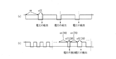
図4は、既存及び本発明に係る全体的なセルバランシング動作の比較例を示す図である。 FIG. 4 is a diagram showing a comparative example of the existing cell balancing operation and the overall cell balancing operation according to the present invention.
図4の(a)は、既存のセルバランシングの制御方法が適用された動作を示す図である。前記図4の(a)に示すように、セルバランシング制御電界効果トランジスタ(FET)にオン/オフが一定の比で動作することを確認することができる。また、前記セルバランシング制御電界効果トランジスタ(FET)がターンオフされた後、セルの電圧を検出する時点も一定していることを確認することができる。しかしながら、この場合には、セルバランシング動作が行われる間に流れるセルバランシング電流によるセルバランシング抵抗の発熱問題とは無関係に一定の時間の比でセルバランシング動作が行われる。これにより、セルバランシング抵抗の発熱問題によりバッテリセル110が損なわれ、且つ、これは、前記セルバランシングの正確性及び効率性を低下させる原因となる虞がある。
FIG. 4A is a diagram showing an operation to which an existing cell balancing control method is applied. As shown in FIG. 4A, it can be confirmed that the cell balancing control field effect transistor (FET) operates at a constant ratio of on / off. It can also be confirmed that the time point at which the cell voltage is detected after the cell balancing control field effect transistor (FET) is turned off is also constant. However, in this case, the cell balancing operation is performed at a constant time ratio regardless of the heat generation problem of the cell balancing resistor due to the cell balancing current flowing during the cell balancing operation. As a result, the
また、一般に、セルバランシング制御電界効果トランジスタ(FET)がターンオフされた後、セル電圧は十分に時間が経過した後に元の開回路電圧(OCV)に回復される。しかしながら、既存には、セルバランシング制御電界効果トランジスタ(FET)がターンオフされた後、セル電圧が開回路電圧(OCV)に回復される時間を考慮せず、一定の時点に電圧を検出し、これは、セル電圧の検出の正確性の低下につながる虞がある。 Also, in general, after the cell balancing control field effect transistor (FET) has been turned off, the cell voltage is restored to its original open circuit voltage (OCV) after a sufficient amount of time has elapsed. However, in the existing, the voltage is detected at a certain time point without considering the time when the cell voltage is restored to the open circuit voltage (OCV) after the cell balancing control field effect transistor (FET) is turned off. May lead to a decrease in the accuracy of cell voltage detection.
これに対し、本発明が適用された図4の(b)を参照すると、セルバランシング動作が行われる間に流れるセルバランシング電流によって発生するセルバランシング抵抗の温度に応じて前記セルバランシング制御電界効果トランジスタ(FET)のオン/オフ周期に対するデューティ比を検出し、これにより、セルバランシング動作が行われることを確認することができる。なお、前記セルバランシング制御電界効果トランジスタ(FET)がターンオフされた後、セル110の電圧を検出する時点もセルの特徴やシステムの特徴に応じて流動的に制御して、セル電圧が開回路電圧(OCV)に回復された後に測定するので、正確性及び効率性が向上したセルバランシング動作が行われる。
On the other hand, referring to FIG. 4B to which the present invention is applied, the cell balancing control field effect transistor according to the temperature of the cell balancing resistor generated by the cell balancing current flowing during the cell balancing operation. It is possible to detect the duty ratio with respect to the on / off cycle of the (FET) and confirm that the cell balancing operation is performed. After the cell balancing control field effect transistor (FET) is turned off, the time when the voltage of the
100:バッテリパック
110:バッテリセル
200:バッテリ管理部
210:セルバランシング動作制御部
220:セルバランシング電流算出部
230:セルバランシング抵抗温度算出部
240:デューティ比算出部
250:電圧検出部
100: Battery pack 110: Battery cell 200: Battery management unit 210: Cell balancing operation control unit 220: Cell balancing current calculation unit 230: Cell balancing resistance temperature calculation unit 240: Duty ratio calculation unit 250: Voltage detection unit
Claims (9)
2つ以上のバッテリセルを備えてなるバッテリパックと、
バッテリセルバランシングを制御するバッテリ管理部と、
を備え、
前記バッテリ管理部は、
バッテリセルのバランシング動作条件の充足の有無を判断し、その判断結果に基づいて、セルバランシング制御電界効果トランジスタにオン/オフ信号を印加してセルバランシング動作を制御するセルバランシング動作制御部と、
セルバランシング動作が行われる間にセルバランシング電流の大きさを測定するセルバランシング電流算出部と、
セルバランシング動作が行われる間に流れる前記セルバランシング電流によって発生するセルバランシング抵抗の温度を算出するセルバランシング抵抗温度算出部と、
前記算出されたセルバランシング抵抗の温度値に応じたセルバランシング制御電界効果トランジスタのオン/オフ周期に対するデューティ比を算出するデューティ比算出部と、
前記バッテリセルの電圧を検出する電圧検出部と、
を備える、バッテリセルのバランシングシステム。 In a battery cell balancing system that balances the voltage of at least two battery cells built into a battery pack.
A battery pack with two or more battery cells and
The battery management unit that controls battery cell balancing and
With
The battery management unit
A cell balancing operation control unit that determines whether or not the balancing operation conditions of the battery cell are satisfied, and based on the determination result, applies an on / off signal to the cell balancing control field effect transistor to control the cell balancing operation.
A cell balancing current calculation unit that measures the magnitude of the cell balancing current while the cell balancing operation is performed,
A cell balancing resistor temperature calculation unit that calculates the temperature of the cell balancing resistor generated by the cell balancing current that flows while the cell balancing operation is performed,
A duty ratio calculation unit that calculates the duty ratio with respect to the on / off period of the cell balancing control field effect transistor according to the calculated temperature value of the cell balancing resistor.
A voltage detector that detects the voltage of the battery cell and
Battery cell balancing system.
前記セルバランシング抵抗温度算出部において算出された抵抗の温度値が属する温度区間を検出し、前記検出された温度区間に対応するセルバランシング制御電界効果トランジスタのオン/オフ信号のデューティ比を算出して、前記セルバランシング動作制御部に与えることを特徴とする請求項1に記載のバッテリセルのバランシングシステム。 The duty ratio calculation unit
The cell balancing resistance temperature calculation unit detects the temperature section to which the temperature value of the resistance belongs, and calculates the duty ratio of the on / off signal of the cell balancing control field effect transistor corresponding to the detected temperature section. The battery cell balancing system according to claim 1, wherein the cell balancing operation control unit is provided with the battery cell balancing system.
前記バッテリセルの電圧の偏差を算出し、前記バッテリセルのそれぞれの電圧偏差のうちの少なくとも1つ以上が所定の基準値以上である場合、バッテリセルバランシングを行う必要があると判断して、バランシングを行う必要があるセルを検出するセル検出部と、
前記セルバランシング制御電界効果トランジスタがオフにされた後、セルバランシングが適用されたセルの電圧を検出し、所定の基準値と比較してセルバランシングの成否を判断するセルバランシング電圧検出部と、
を備えてなることを特徴とする請求項1に記載のバッテリセルのバランシングシステム。 The voltage detection unit
The voltage deviation of the battery cells is calculated, and when at least one or more of the voltage deviations of the battery cells is equal to or more than a predetermined reference value, it is determined that battery cell balancing is necessary and balancing is performed. And the cell detector that detects the cells that need to be
After the cell balancing control field effect transistor is turned off, the cell balancing voltage detector that detects the voltage of the cell to which the cell balancing is applied and compares it with a predetermined reference value to determine the success or failure of the cell balancing.
The battery cell balancing system according to claim 1, wherein the battery cell balancing system is provided.
前記セルバランシング制御電界効果トランジスタがオフにされた後、所定の時間が経過した後に動作することを特徴とする請求項3に記載のバッテリセルのバランシングシステム。 The cell balancing voltage detector is
The battery cell balancing system according to claim 3, wherein the cell balancing control field effect transistor operates after a predetermined time has elapsed after the transistor is turned off.
セルバランシングが始まる段階では、セルバランシング制御電界効果トランジスタを所定のデューティ比を有するオン/オフ制御信号で制御し、その後、セルバランシング動作の際に発生する抵抗の温度に応じて算出されたデューティ比でセルバランシング制御電界効果トランジスタのオン/オフを制御することを特徴とする請求項1に記載のバッテリセルのバランシングシステム。 The cell balancing operation control unit
At the stage when cell balancing starts, the cell balancing control field effect transistor is controlled by an on / off control signal having a predetermined duty ratio, and then the duty ratio calculated according to the temperature of the resistor generated during the cell balancing operation. Cell Balancing Control The battery cell balancing system according to claim 1, wherein the field effect transistor is controlled on / off.
バッテリセルのバランシング動作条件の充足の有無を判断し、その判断結果に基づいて、セルバランシング制御電界効果トランジスタにオン/オフ信号を印加してセルバランシング動作を制御するセルバランシング動作判断ステップと、
セルバランシング動作が行われる間に流れるセルバランシング電流の大きさを測定して算出するセルバランシング電流算出ステップと、
セルバランシング動作が行われる間に流れるセルバランシング電流によって発生するセルバランシング抵抗の温度を算出するセルバランシング抵抗温度算出ステップと、
前記算出されたセルバランシング抵抗の温度値に応じたセルバランシング制御電界効果トランジスタのオン/オフ周期に対するデューティ比を算出するデューティ比算出ステップと、
前記算出されたデューティ比に基づいて、セルバランシング制御電界効果トランジスタにオン/オフ信号を印加してセルバランシング動作を行うセルバランシング動作ステップと、
前記バッテリセルの電圧を検出する電圧検出ステップと、
を含むバッテリセルのバランシング方法。 In a battery cell balancing method that balances the voltages of at least two or more battery cells built into a battery pack.
A cell balancing operation determination step that determines whether or not the battery cell balancing operation conditions are satisfied, and based on the determination result, applies an on / off signal to the cell balancing control field effect transistor to control the cell balancing operation.
A cell balancing current calculation step that measures and calculates the magnitude of the cell balancing current that flows during the cell balancing operation, and
A cell balancing resistor temperature calculation step that calculates the temperature of the cell balancing resistor generated by the cell balancing current that flows during the cell balancing operation, and
The duty ratio calculation step of calculating the duty ratio with respect to the on / off period of the cell balancing control field effect transistor according to the calculated temperature value of the cell balancing resistor, and
Based on the calculated duty ratio, the cell balancing operation step of applying an on / off signal to the cell balancing control field effect transistor to perform the cell balancing operation, and the cell balancing operation step.
A voltage detection step for detecting the voltage of the battery cell and
Battery cell balancing method, including.
前記セルバランシング抵抗温度算出ステップにおいて算出された抵抗の温度値が属する温度区間を検出し、前記検出された温度区間に対応するセルバランシング制御電界効果トランジスタのオン/オフ信号のデューティ比を算出することを特徴とする請求項6に記載のバッテリセルのバランシング方法。 In the duty ratio calculation step,
Detecting the temperature section to which the temperature value of the resistor calculated in the cell balancing resistance temperature calculation step belongs, and calculating the duty ratio of the on / off signal of the cell balancing control field effect transistor corresponding to the detected temperature section. The battery cell balancing method according to claim 6, wherein the battery cell is balanced.
前記セルバランシング制御電界効果トランジスタがオフにされた後、所定の時間が経過した後にセルバランシングが適用されたセルの電圧を検出し、所定の基準値と比較してセルバランシングの成否を判断することを特徴とする請求項6に記載のバッテリセルのバランシング方法。 In the voltage detection step,
After the cell balancing control field effect transistor is turned off, the voltage of the cell to which the cell balancing is applied is detected after a predetermined time has elapsed, and the success or failure of the cell balancing is judged by comparing with the predetermined reference value. The battery cell balancing method according to claim 6.
セルバランシング動作が始まる段階では、セルバランシング制御電界効果トランジスタを所定のデューティ比を有するオン/オフ制御信号でオン/オフ制御し、その後、デューティ比算出ステップにおいて算出されるセルバランシング制御電界効果トランジスタ(FET)のオン/オフデューティ比に基づいて、オン/オフ信号を印加することを特徴とする請求項6に記載のバッテリセルのバランシング方法。 In the cell balancing operation determination step,
At the stage when the cell balancing operation starts, the cell balancing control field effect transistor is on / off controlled by the on / off control signal having a predetermined duty ratio, and then the cell balancing control field effect transistor calculated in the duty ratio calculation step ( The battery cell balancing method according to claim 6, wherein an on / off signal is applied based on the on / off duty ratio of the FET).
Applications Claiming Priority (2)
| Application Number | Priority Date | Filing Date | Title |
|---|---|---|---|
| KR10-2016-0137840 | 2016-10-21 | ||
| KR1020160137840A KR102167428B1 (en) | 2016-10-21 | 2016-10-21 | Effective battery cell-balancing method and system through the duty control |
Related Parent Applications (1)
| Application Number | Title | Priority Date | Filing Date |
|---|---|---|---|
| JP2018535371A Division JP2019504451A (en) | 2016-10-21 | 2017-10-17 | Effective battery cell balancing method and system using duty control |
Publications (2)
| Publication Number | Publication Date |
|---|---|
| JP2020174530A true JP2020174530A (en) | 2020-10-22 |
| JP7072607B2 JP7072607B2 (en) | 2022-05-20 |
Family
ID=62018617
Family Applications (2)
| Application Number | Title | Priority Date | Filing Date |
|---|---|---|---|
| JP2018535371A Pending JP2019504451A (en) | 2016-10-21 | 2017-10-17 | Effective battery cell balancing method and system using duty control |
| JP2020117776A Active JP7072607B2 (en) | 2016-10-21 | 2020-07-08 | Effective Battery Cell Balancing Methods and Systems Using Duty Control |
Family Applications Before (1)
| Application Number | Title | Priority Date | Filing Date |
|---|---|---|---|
| JP2018535371A Pending JP2019504451A (en) | 2016-10-21 | 2017-10-17 | Effective battery cell balancing method and system using duty control |
Country Status (6)
| Country | Link |
|---|---|
| US (1) | US10840711B2 (en) |
| EP (1) | EP3396774A4 (en) |
| JP (2) | JP2019504451A (en) |
| KR (1) | KR102167428B1 (en) |
| CN (1) | CN108604711B (en) |
| WO (1) | WO2018074807A1 (en) |
Families Citing this family (14)
| Publication number | Priority date | Publication date | Assignee | Title |
|---|---|---|---|---|
| FR2944007B1 (en) | 2009-04-03 | 2012-06-08 | Sgd Sa | PROCESS FOR MANUFACTURING A GLASS CONTAINER AND CORRESPONDING CONTAINER. |
| WO2019171662A1 (en) * | 2018-03-08 | 2019-09-12 | 三洋電機株式会社 | Management device and electricity storage system |
| KR102500362B1 (en) * | 2018-10-19 | 2023-02-14 | 주식회사 엘지에너지솔루션 | Apparatus for managing battery |
| KR102556994B1 (en) | 2019-02-20 | 2023-07-17 | 삼성에스디아이 주식회사 | Method and battery management sytem for controlling cell balancing |
| JP7196034B2 (en) * | 2019-06-11 | 2022-12-26 | エイブリック株式会社 | Charge/discharge control circuit and battery device provided with the same |
| US11539221B2 (en) * | 2019-06-11 | 2022-12-27 | Ablic Inc. | Charge-discharge control circuit including cell balancing circuits, cell balance detection circuits, overcharge detection circuits, and a control circuit |
| KR102225270B1 (en) | 2020-09-04 | 2021-03-10 | 주식회사 패러다임 | Apparatus for battery balancing |
| CN112595984B (en) * | 2020-12-14 | 2021-12-14 | 珠海格力电器股份有限公司 | Lithium battery voltage detection method and device, electrical equipment and storage medium |
| KR20230152429A (en) * | 2022-04-27 | 2023-11-03 | 주식회사 엘지에너지솔루션 | Cell balancing method and battery pack with it applied |
| CN114967815B (en) * | 2022-06-23 | 2024-12-17 | 广东美的白色家电技术创新中心有限公司 | Voltage regulating device, method, device, equipment and medium |
| CN114879802B (en) * | 2022-06-23 | 2024-10-29 | 广东美的白色家电技术创新中心有限公司 | Current regulation device, method, device, equipment and medium |
| KR102830328B1 (en) * | 2022-11-28 | 2025-07-03 | 삼성에스디아이 주식회사 | Abnormal cell detection method, abnormal cell detection device, and battery pack |
| WO2025088588A1 (en) * | 2023-10-26 | 2025-05-01 | Ather Energy Limited | Method and system for balancing battery pack of electric vehicle |
| KR20250113758A (en) * | 2024-01-19 | 2025-07-28 | 스탠다드에너지(주) | Method for Snapshot Balancing of the Battery and System for the Same |
Citations (6)
| Publication number | Priority date | Publication date | Assignee | Title |
|---|---|---|---|---|
| JP2012115101A (en) * | 2010-11-26 | 2012-06-14 | Keihin Corp | Cell balance controller |
| WO2013021589A1 (en) * | 2011-08-11 | 2013-02-14 | パナソニック株式会社 | Equalizer circuit, power supply system, and vehicle |
| US20130113280A1 (en) * | 2011-11-04 | 2013-05-09 | Samsung Sdi Co., Ltd. | Apparatus and method for managing battery cell, and energy storage system |
| JP2014183727A (en) * | 2013-03-21 | 2014-09-29 | Toyota Motor Corp | Power storage system |
| JP2015070653A (en) * | 2013-09-27 | 2015-04-13 | 株式会社豊田自動織機 | Battery voltage equalization control device and method |
| JP2015133766A (en) * | 2012-04-27 | 2015-07-23 | 三洋電機株式会社 | Power supply unit and vehicle including power supply unit |
Family Cites Families (18)
| Publication number | Priority date | Publication date | Assignee | Title |
|---|---|---|---|---|
| CA2406500C (en) * | 2001-10-01 | 2008-04-01 | Research In Motion Limited | An over-voltage protection circuit for use in a charging circuit |
| JP4065232B2 (en) * | 2003-12-11 | 2008-03-19 | 三洋電機株式会社 | How to charge the battery |
| US8044637B2 (en) * | 2008-09-29 | 2011-10-25 | The United States Of America As Represented By The Secretary Of The Navy | Battery charging method |
| US8350528B2 (en) * | 2009-02-04 | 2013-01-08 | Samsung Sdi Co., Ltd. | Battery pack and balancing method of battery cells |
| KR101147168B1 (en) * | 2010-09-09 | 2012-05-25 | (주)이미지스테크놀로지 | System for control cell balance of battery pack using eq cell and method thereof |
| JP5632723B2 (en) * | 2010-11-26 | 2014-11-26 | 株式会社ケーヒン | Cell balance control device |
| US9746525B2 (en) * | 2011-09-08 | 2017-08-29 | Hitachi Automotive Systems, Ltd. | Battery system monitoring device |
| KR101473324B1 (en) * | 2011-11-04 | 2014-12-16 | 삼성에스디아이 주식회사 | Apparatus for managing battery, method for balancing battery cells, and energy storage system |
| JP2013123274A (en) | 2011-12-09 | 2013-06-20 | Nissan Motor Co Ltd | Battery pack controller |
| JP2013236492A (en) | 2012-05-09 | 2013-11-21 | Panasonic Corp | Battery module and battery management system |
| KR102028170B1 (en) | 2012-08-13 | 2019-10-02 | 삼성에스디아이 주식회사 | cell balancing circuit and battery pack having the same |
| JP5892024B2 (en) * | 2012-10-01 | 2016-03-23 | 株式会社豊田自動織機 | Power supply device and battery module switching method |
| KR101459539B1 (en) | 2012-12-27 | 2014-11-07 | 현대모비스 주식회사 | Apparatus and method for uniform energy of battery cell |
| TWI627812B (en) * | 2013-04-05 | 2018-06-21 | 美商線性科技股份有限公司 | Device, system and method for voltage compensation active battery balancing |
| KR20150004035A (en) * | 2013-07-02 | 2015-01-12 | 현대자동차주식회사 | Method and system for balancing battery cell |
| CN103441542B (en) * | 2013-08-13 | 2015-02-11 | 天津谷泰科技有限公司 | Lithium battery distributed charging equalization circuit and control method thereof |
| KR101631065B1 (en) * | 2013-12-03 | 2016-06-16 | 삼성에스디아이 주식회사 | Battery system and method for connecting battery |
| KR101601721B1 (en) * | 2014-12-08 | 2016-03-09 | 현대오트론 주식회사 | Apparatus and method for discharging battery |
-
2016
- 2016-10-21 KR KR1020160137840A patent/KR102167428B1/en active Active
-
2017
- 2017-10-17 CN CN201780008545.9A patent/CN108604711B/en active Active
- 2017-10-17 EP EP17861377.4A patent/EP3396774A4/en active Pending
- 2017-10-17 US US16/076,431 patent/US10840711B2/en active Active
- 2017-10-17 WO PCT/KR2017/011445 patent/WO2018074807A1/en not_active Ceased
- 2017-10-17 JP JP2018535371A patent/JP2019504451A/en active Pending
-
2020
- 2020-07-08 JP JP2020117776A patent/JP7072607B2/en active Active
Patent Citations (6)
| Publication number | Priority date | Publication date | Assignee | Title |
|---|---|---|---|---|
| JP2012115101A (en) * | 2010-11-26 | 2012-06-14 | Keihin Corp | Cell balance controller |
| WO2013021589A1 (en) * | 2011-08-11 | 2013-02-14 | パナソニック株式会社 | Equalizer circuit, power supply system, and vehicle |
| US20130113280A1 (en) * | 2011-11-04 | 2013-05-09 | Samsung Sdi Co., Ltd. | Apparatus and method for managing battery cell, and energy storage system |
| JP2015133766A (en) * | 2012-04-27 | 2015-07-23 | 三洋電機株式会社 | Power supply unit and vehicle including power supply unit |
| JP2014183727A (en) * | 2013-03-21 | 2014-09-29 | Toyota Motor Corp | Power storage system |
| JP2015070653A (en) * | 2013-09-27 | 2015-04-13 | 株式会社豊田自動織機 | Battery voltage equalization control device and method |
Also Published As
| Publication number | Publication date |
|---|---|
| US20190052098A1 (en) | 2019-02-14 |
| KR102167428B1 (en) | 2020-10-20 |
| JP2019504451A (en) | 2019-02-14 |
| WO2018074807A1 (en) | 2018-04-26 |
| JP7072607B2 (en) | 2022-05-20 |
| EP3396774A4 (en) | 2019-03-13 |
| US10840711B2 (en) | 2020-11-17 |
| KR20180044485A (en) | 2018-05-03 |
| CN108604711A (en) | 2018-09-28 |
| EP3396774A1 (en) | 2018-10-31 |
| CN108604711B (en) | 2021-06-29 |
Similar Documents
| Publication | Publication Date | Title |
|---|---|---|
| JP7072607B2 (en) | Effective Battery Cell Balancing Methods and Systems Using Duty Control | |
| CN108539300B (en) | Cell balance method and system for battery pack | |
| JP7173127B2 (en) | BATTERY MONITORING METHOD, BATTERY MONITORING DEVICE, AND BATTERY MONITORING SYSTEM | |
| JP5499200B2 (en) | Degradation determination apparatus, deterioration determination method, and program | |
| US11456610B2 (en) | Internal short sensing battery control apparatus and battery control method | |
| US10209317B2 (en) | Battery control device for calculating battery deterioration based on internal resistance increase rate | |
| TWI639288B (en) | Battery pack balancing method and system | |
| JP5460943B2 (en) | Degradation judgment device, degradation judgment method, computer program | |
| JP2008253129A (en) | Rapid charging method for lithium secondary battery and electronic device using the same | |
| CN115244413B (en) | Methods and equipment for calculating battery aging degree | |
| JP5743634B2 (en) | Deterioration measuring device, secondary battery pack, deterioration measuring method, and program | |
| US20080180061A1 (en) | Cell balancing battery pack and method of balancing the cells of a battery | |
| JP6101714B2 (en) | Battery control device, battery system | |
| CN103138026A (en) | Battery pack control device | |
| JP2016166864A (en) | Storage element management device, storage element management method, storage element module, storage element management program, and moving body | |
| JP2004271342A (en) | Charge / discharge control system | |
| JP5473277B2 (en) | Charger | |
| KR102158259B1 (en) | System and the battery which upon failure of the battery pack analysis method and system | |
| JP2020024120A (en) | Voltage estimation device and method | |
| JP2004014462A (en) | Remaining battery capacity measurement device | |
| JP2001015178A (en) | Battery pack and its voltage balance measuring device | |
| KR101748917B1 (en) | Apparatus and Method for diagnosing battery balancing | |
| US20260126491A1 (en) | Intelligent power management system, including autonomous battery self-characterization |
Legal Events
| Date | Code | Title | Description |
|---|---|---|---|
| A521 | Request for written amendment filed |
Free format text: JAPANESE INTERMEDIATE CODE: A523 Effective date: 20200709 |
|
| A621 | Written request for application examination |
Free format text: JAPANESE INTERMEDIATE CODE: A621 Effective date: 20200709 |
|
| A977 | Report on retrieval |
Free format text: JAPANESE INTERMEDIATE CODE: A971007 Effective date: 20210730 |
|
| A131 | Notification of reasons for refusal |
Free format text: JAPANESE INTERMEDIATE CODE: A131 Effective date: 20210823 |
|
| A521 | Request for written amendment filed |
Free format text: JAPANESE INTERMEDIATE CODE: A523 Effective date: 20211115 |
|
| A711 | Notification of change in applicant |
Free format text: JAPANESE INTERMEDIATE CODE: A712 Effective date: 20211222 |
|
| TRDD | Decision of grant or rejection written | ||
| A01 | Written decision to grant a patent or to grant a registration (utility model) |
Free format text: JAPANESE INTERMEDIATE CODE: A01 Effective date: 20220411 |
|
| A61 | First payment of annual fees (during grant procedure) |
Free format text: JAPANESE INTERMEDIATE CODE: A61 Effective date: 20220510 |
|
| R150 | Certificate of patent or registration of utility model |
Ref document number: 7072607 Country of ref document: JP Free format text: JAPANESE INTERMEDIATE CODE: R150 |
|
| R250 | Receipt of annual fees |
Free format text: JAPANESE INTERMEDIATE CODE: R250 |