JP2020176933A - 角度検出装置 - Google Patents
角度検出装置 Download PDFInfo
- Publication number
- JP2020176933A JP2020176933A JP2019079808A JP2019079808A JP2020176933A JP 2020176933 A JP2020176933 A JP 2020176933A JP 2019079808 A JP2019079808 A JP 2019079808A JP 2019079808 A JP2019079808 A JP 2019079808A JP 2020176933 A JP2020176933 A JP 2020176933A
- Authority
- JP
- Japan
- Prior art keywords
- signal
- sine signal
- angle
- sine
- detection
- Prior art date
- Legal status (The legal status is an assumption and is not a legal conclusion. Google has not performed a legal analysis and makes no representation as to the accuracy of the status listed.)
- Granted
Links
Images




Classifications
-
- G—PHYSICS
- G01—MEASURING; TESTING
- G01D—MEASURING NOT SPECIALLY ADAPTED FOR A SPECIFIC VARIABLE; ARRANGEMENTS FOR MEASURING TWO OR MORE VARIABLES NOT COVERED IN A SINGLE OTHER SUBCLASS; TARIFF METERING APPARATUS; MEASURING OR TESTING NOT OTHERWISE PROVIDED FOR
- G01D5/00—Mechanical means for transferring the output of a sensing member; Means for converting the output of a sensing member to another variable where the form or nature of the sensing member does not constrain the means for converting; Transducers not specially adapted for a specific variable
- G01D5/12—Mechanical means for transferring the output of a sensing member; Means for converting the output of a sensing member to another variable where the form or nature of the sensing member does not constrain the means for converting; Transducers not specially adapted for a specific variable using electric or magnetic means
- G01D5/14—Mechanical means for transferring the output of a sensing member; Means for converting the output of a sensing member to another variable where the form or nature of the sensing member does not constrain the means for converting; Transducers not specially adapted for a specific variable using electric or magnetic means influencing the magnitude of a current or voltage
- G01D5/142—Mechanical means for transferring the output of a sensing member; Means for converting the output of a sensing member to another variable where the form or nature of the sensing member does not constrain the means for converting; Transducers not specially adapted for a specific variable using electric or magnetic means influencing the magnitude of a current or voltage using Hall-effect devices
- G01D5/145—Mechanical means for transferring the output of a sensing member; Means for converting the output of a sensing member to another variable where the form or nature of the sensing member does not constrain the means for converting; Transducers not specially adapted for a specific variable using electric or magnetic means influencing the magnitude of a current or voltage using Hall-effect devices influenced by the relative movement between the Hall device and magnetic fields
-
- G—PHYSICS
- G01—MEASURING; TESTING
- G01D—MEASURING NOT SPECIALLY ADAPTED FOR A SPECIFIC VARIABLE; ARRANGEMENTS FOR MEASURING TWO OR MORE VARIABLES NOT COVERED IN A SINGLE OTHER SUBCLASS; TARIFF METERING APPARATUS; MEASURING OR TESTING NOT OTHERWISE PROVIDED FOR
- G01D5/00—Mechanical means for transferring the output of a sensing member; Means for converting the output of a sensing member to another variable where the form or nature of the sensing member does not constrain the means for converting; Transducers not specially adapted for a specific variable
- G01D5/12—Mechanical means for transferring the output of a sensing member; Means for converting the output of a sensing member to another variable where the form or nature of the sensing member does not constrain the means for converting; Transducers not specially adapted for a specific variable using electric or magnetic means
- G01D5/244—Mechanical means for transferring the output of a sensing member; Means for converting the output of a sensing member to another variable where the form or nature of the sensing member does not constrain the means for converting; Transducers not specially adapted for a specific variable using electric or magnetic means influencing characteristics of pulses or pulse trains; generating pulses or pulse trains
- G01D5/24428—Error prevention
-
- G—PHYSICS
- G01—MEASURING; TESTING
- G01D—MEASURING NOT SPECIALLY ADAPTED FOR A SPECIFIC VARIABLE; ARRANGEMENTS FOR MEASURING TWO OR MORE VARIABLES NOT COVERED IN A SINGLE OTHER SUBCLASS; TARIFF METERING APPARATUS; MEASURING OR TESTING NOT OTHERWISE PROVIDED FOR
- G01D3/00—Indicating or recording apparatus with provision for the special purposes referred to in the subgroups
- G01D3/028—Indicating or recording apparatus with provision for the special purposes referred to in the subgroups mitigating undesired influences, e.g. temperature, pressure
- G01D3/036—Indicating or recording apparatus with provision for the special purposes referred to in the subgroups mitigating undesired influences, e.g. temperature, pressure on measuring arrangements themselves
-
- G—PHYSICS
- G01—MEASURING; TESTING
- G01D—MEASURING NOT SPECIALLY ADAPTED FOR A SPECIFIC VARIABLE; ARRANGEMENTS FOR MEASURING TWO OR MORE VARIABLES NOT COVERED IN A SINGLE OTHER SUBCLASS; TARIFF METERING APPARATUS; MEASURING OR TESTING NOT OTHERWISE PROVIDED FOR
- G01D5/00—Mechanical means for transferring the output of a sensing member; Means for converting the output of a sensing member to another variable where the form or nature of the sensing member does not constrain the means for converting; Transducers not specially adapted for a specific variable
- G01D5/12—Mechanical means for transferring the output of a sensing member; Means for converting the output of a sensing member to another variable where the form or nature of the sensing member does not constrain the means for converting; Transducers not specially adapted for a specific variable using electric or magnetic means
- G01D5/244—Mechanical means for transferring the output of a sensing member; Means for converting the output of a sensing member to another variable where the form or nature of the sensing member does not constrain the means for converting; Transducers not specially adapted for a specific variable using electric or magnetic means influencing characteristics of pulses or pulse trains; generating pulses or pulse trains
- G01D5/24471—Error correction
- G01D5/2448—Correction of gain, threshold, offset or phase control
Landscapes
- Physics & Mathematics (AREA)
- General Physics & Mathematics (AREA)
- Transmission And Conversion Of Sensor Element Output (AREA)
Abstract
Description
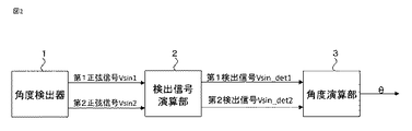
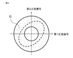
回転機の回転に応じて第1正弦信号と第1正弦信号と位相の異なる第2正弦信号とを検出する角度検出器、
第1正弦信号と第2正弦信号の和に基づいた第1検出信号と第1正弦信号と第2正弦信号の差に基づいた第2検出信号とを出力する検出信号演算部、
第1検出信号と第2検出信号に基づいて検出角を演算する角度演算部、
を備え、第1正弦信号と第2正弦信号の位相差がπ/2からずれることによって生じる2次の角度誤差を抑制することを特徴とするものである。
本願の角度検出装置に使用する角度検出器1としては、レゾルバ、磁気抵抗素子を利用したセンサ(MRセンサ)、エンコーダ、ホール素子などが挙げられるが、いずれの場合においても同様の効果が得られるため、ここではMRセンサを例として説明する。

第1検出信号および第2検出信号の振幅が、ともに元信号の振幅以上となるための条件は、式(1)および式(2)より、式(9−1)となる。
位相差がπ/2の場合には、第1検出信号Vsin_det1および第2検出信号Vsin_det2の振幅がともに元信号である第1正弦信号Vsin1および第2正弦信号Vsin2の√2倍となるため、A/D変換の分解能による精度低下を抑制しつつ、元信号である第1正弦信号Vsin1および第2正弦信号Vsin2の位相差ずれを第1検出信号Vsin_det1と第2検出信号Vsin_det2の振幅比ずれに置換することができる。この効果について、第1正弦信号Vsin1および第2正弦信号Vsin2が式(10)のように与えられた場合を例として説明する。
なお、式(11)および式(12)では第1正弦信号Vsin1と第2正弦信号Vsin2でオフセットを補正したが、第1検出信号Vsin_det1と第2検出信号Vsin_det2でオフセットを補正してもよい。この場合、式(13)で第1正弦信号Vsin1と第2正弦信号Vsin2の振幅比を1に合わせる。このとき、第1正弦信号Vsin1のオフセットa0に補正係数がかかることになるが、式(14)のように誤差の積は微小と近似できる。
前記実施の形態1では、第1正弦信号Vsin1と第2正弦信号Vsin2の和から得られた第1検出信号Vsin_det1と第1正弦信号Vsin1と第2正弦信号Vsin2の差から得られた第2検出信号Vsin_det2を用いて検出角を演算することによって、第1正弦信号Vsin1と第2正弦信号Vsin2の位相差ずれによって生じる2次の角度誤差を抑制する方法について説明したが、本実施の形態3では故障判定方法について説明する。
従って、例示されていない無数の変形例が、本願明細書に開示される技術の範囲内において想定される。例えば、少なくとも1つの構成要素を変形する場合、追加する場合または省略する場合、さらには、少なくとも1つの構成要素を抽出し、他の実施の形態の構成要素と組み合わせる場合が含まれるものとする。
前記第1正弦信号と前記第2正弦信号の和に基づいた第1検出信号と前記第1正弦信号と前記第2正弦信号の差に基づいた第2検出信号とを出力する検出信号演算部、
前記第1検出信号と、前記第2検出信号を√3倍したものに基づいて検出角を演算する角度演算部、
を備え、前記第1正弦信号と前記第2正弦信号の位相差がπ/2からずれることによって生じる2次の角度誤差を抑制することを特徴とするものである。
回転機の回転に応じて第1正弦信号と前記第1正弦信号とπ/3だけ位相の異なる第2正弦信号とを検出する角度検出器、
角度検出器で検出された第1正弦信号と第2正弦信号をA/D変換するA/D変換器、
第1正弦信号をA/D変換器で変換した第1の値と第2正弦信号をA/D変換器で変換した第2の値との和に基づいた第1検出信号と、第1の値と第2の値との差に基づいた第2検出信号とを出力する検出信号演算部、
第1の値と、第2の値を√3倍した値に基づいて検出角を演算する角度演算部、を備え、第1正弦信号と第2正弦信号の位相差がπ/2からずれることによって生じる2次の角度誤差を抑制することを特徴とするものである。
Claims (15)
- 回転機の回転に応じて第1正弦信号と前記第1正弦信号と位相の異なる第2正弦信号とを検出する角度検出器、
前記第1正弦信号と前記第2正弦信号の和に基づいた第1検出信号と前記第1正弦信号と前記第2正弦信号の差に基づいた第2検出信号とを出力する検出信号演算部、
前記第1検出信号と前記第2検出信号に基づいて検出角を演算する角度演算部、を備え、前記第1正弦信号と前記第2正弦信号の位相差がπ/2からずれることによって生じる2次の角度誤差を抑制することを特徴とする角度検出装置。 - 前記第1検出信号は、前記第1正弦信号と前記第2正弦信号の和から予め定められた値を減算して算出することを特徴とする請求項1に記載の角度検出装置。
- 前記予め定められた値は、前記第1正弦信号の中点電位の2倍であることを特徴とする請求項2に記載の角度検出装置。
- 前記予め定められた値は、前記角度検出器に供給される直流電圧であることを特徴とする請求項2に記載の角度検出装置。
- 前記予め定められた値は、オンラインで設定可能であることを特徴とする請求項2から4のいずれか1項に記載の角度検出装置。
- 前記角度演算部で算出する角度検出値は、
前記第1検出信号と前記第2検出信号の比の逆正接関数によって得られる角度から、
前記第1正弦信号と前記第2正弦信号の位相差の1/2の値または前記第1正弦信号と前記第2正弦信号の位相差の1/2にπ/2を加算した値を減算して算出することを特徴とする請求項1から5のいずれか1項に記載の角度検出装置。 - 前記第1正弦信号または前記第2正弦信号の少なくとも一方に対して、前記第1正弦信号と前記第2正弦信号の振幅比を1とするように補正することを特徴とする請求項1から6のいずれか1項に記載の角度検出装置。
- 前記第1正弦信号を第1のオフセット補正値を減算して補正し、前記第2正弦信号を第2のオフセット補正値を減算して補正することを特徴とする請求項1から7のいずれか1項に記載の角度検出装置。
- 前記角度検出器の故障を判定する故障判定器を更に備え、前記故障判定器は、前記第1検出信号と前記第2検出信号の二乗和または二乗和平方根を用いて故障を判定することを特徴とする請求項1から8のいずれか1項に記載の角度検出装置。
- 前記第1検出信号と前記第2検出信号の少なくとも一方に対して、振幅比に基づく補正係数を乗じて補正することを特徴とする請求項1から9のいずれか1項に記載の角度検出装置。
- 前記第1検出信号と前記第2検出信号のうち、振幅が小さい方の信号に対して振幅比に基づく1以上の補正係数を乗じて補正することを特徴とする請求項1から9のいずれか1項に記載の角度検出装置。
-
前記第1正弦信号と前記第2正弦信号の位相差は、π/3以上2/3π以下であることを特徴とする請求項1から11のいずれか1項に記載の角度検出装置。 - 前記第1正弦信号と前記第2正弦信号の位相差は、π/2であることを特徴とする請求項1から11のいずれか1項に記載の角度検出装置。
- 前記第1正弦信号と前記第2正弦信号の位相差は、π/3または2/3πであることを特徴とする請求項1から11のいずれか1項に記載の角度検出装置。
- 前記角度検出器は、レゾルバ、磁気抵抗を利用したセンサ、エンコーダ、またはホール素子のいずれかであることを特徴とする請求項1から14のいずれか1項に記載の角度検出装置。
Priority Applications (5)
| Application Number | Priority Date | Filing Date | Title |
|---|---|---|---|
| JP2019079808A JP6854841B2 (ja) | 2019-04-19 | 2019-04-19 | 角度検出装置 |
| EP19925337.8A EP3957959B1 (en) | 2019-04-19 | 2019-07-04 | Angle detection device |
| US17/442,706 US12345553B2 (en) | 2019-04-19 | 2019-07-04 | Angle detection device |
| PCT/JP2019/026583 WO2020213181A1 (ja) | 2019-04-19 | 2019-07-04 | 角度検出装置 |
| CN201980095191.5A CN113661375B (zh) | 2019-04-19 | 2019-07-04 | 角度检测装置 |
Applications Claiming Priority (1)
| Application Number | Priority Date | Filing Date | Title |
|---|---|---|---|
| JP2019079808A JP6854841B2 (ja) | 2019-04-19 | 2019-04-19 | 角度検出装置 |
Publications (2)
| Publication Number | Publication Date |
|---|---|
| JP2020176933A true JP2020176933A (ja) | 2020-10-29 |
| JP6854841B2 JP6854841B2 (ja) | 2021-04-07 |
Family
ID=72837284
Family Applications (1)
| Application Number | Title | Priority Date | Filing Date |
|---|---|---|---|
| JP2019079808A Active JP6854841B2 (ja) | 2019-04-19 | 2019-04-19 | 角度検出装置 |
Country Status (5)
| Country | Link |
|---|---|
| US (1) | US12345553B2 (ja) |
| EP (1) | EP3957959B1 (ja) |
| JP (1) | JP6854841B2 (ja) |
| CN (1) | CN113661375B (ja) |
| WO (1) | WO2020213181A1 (ja) |
Families Citing this family (3)
| Publication number | Priority date | Publication date | Assignee | Title |
|---|---|---|---|---|
| KR102655067B1 (ko) * | 2021-12-16 | 2024-04-05 | 현대오토에버 주식회사 | 신호 처리장치 |
| DE112022005805T5 (de) * | 2022-03-18 | 2024-10-24 | Hitachi Astemo, Ltd. | Motorsteuervorrichtung und magnetpolpositions-berechnungsverfahren |
| CN114910112B (zh) * | 2022-07-15 | 2022-09-23 | 泉州昆泰芯微电子科技有限公司 | 信号误差校正方法、磁性编码器及光学编码器 |
Citations (14)
| Publication number | Priority date | Publication date | Assignee | Title |
|---|---|---|---|---|
| JPS60170710A (ja) * | 1984-02-15 | 1985-09-04 | Asahi Optical Co Ltd | 測角誤差の補正装置 |
| JP2003149003A (ja) * | 2001-11-14 | 2003-05-21 | Mitsutoyo Corp | エンコーダの位相差補正装置、位相差補正方法及び位相差補正プログラム |
| WO2007055135A1 (ja) * | 2005-11-14 | 2007-05-18 | Kabushiki Kaisha Yaskawa Denki | 磁気式エンコーダ装置 |
| JP2008134215A (ja) * | 2006-10-30 | 2008-06-12 | Hitachi Ltd | Gmr素子を用いた変位センサ,gmr素子を用いた角度検出センサ及びそれらに用いる半導体装置 |
| JP2010048760A (ja) * | 2008-08-25 | 2010-03-04 | Jtekt Corp | レゾルバの異常検出装置および電気式動力舵取装置 |
| JP2011117834A (ja) * | 2009-12-03 | 2011-06-16 | Canon Inc | 位置信号補正装置および位置信号補正方法 |
| JP2013108971A (ja) * | 2011-10-25 | 2013-06-06 | Ricoh Co Ltd | 角度検出装置、モータ駆動装置及び画像形成装置 |
| JP2015508899A (ja) * | 2012-02-29 | 2015-03-23 | ツエントルム・ミクロエレクトロニク・ドレスデン・アクチエンゲゼルシャフト | 動く物体の絶対位置を冗長的に計測する装置及び方法 |
| US20150247746A1 (en) * | 2012-11-14 | 2015-09-03 | Baumueller Nuernberg Gmbh | Method for calibrating a rotary encoder |
| JP2015206614A (ja) * | 2014-04-17 | 2015-11-19 | 株式会社ニコン | エンコーダ装置および補正方法 |
| JP2017125866A (ja) * | 2017-04-27 | 2017-07-20 | パナソニックIpマネジメント株式会社 | 光学式エンコーダ |
| JP2017151061A (ja) * | 2016-02-26 | 2017-08-31 | 株式会社東京精密 | 内挿方法及び内挿装置 |
| JP2018054584A (ja) * | 2016-09-30 | 2018-04-05 | Tdk株式会社 | 角度センサおよび角度センサシステム |
| JP2018100858A (ja) * | 2016-12-19 | 2018-06-28 | Tdk株式会社 | 角度センサの補正装置および角度センサ |
Family Cites Families (17)
| Publication number | Priority date | Publication date | Assignee | Title |
|---|---|---|---|---|
| JP2003009565A (ja) * | 2001-06-26 | 2003-01-10 | Sony Corp | 角度/位置検出装置およびそれを用いたモータ制御装置 |
| JP2008273478A (ja) | 2007-05-07 | 2008-11-13 | Mitsubishi Electric Corp | 電動パワーステアリング制御装置 |
| JP5469053B2 (ja) * | 2010-12-22 | 2014-04-09 | オークマ株式会社 | 位置速度制御装置 |
| JP2013205366A (ja) * | 2012-03-29 | 2013-10-07 | Mitsubishi Electric Corp | 位置検出器 |
| DE102014201758A1 (de) * | 2014-01-31 | 2015-08-06 | Robert Bosch Gmbh | Steuervorrichtung für eine elektromaschine, verfahren und motorsteuerung |
| JP6492917B2 (ja) * | 2014-04-25 | 2019-04-03 | 株式会社リコー | 角度検出装置、モータ駆動制御装置、及びモータ装置 |
| JP3215077U (ja) * | 2015-01-23 | 2018-03-01 | インフィネオン テクノロジーズ アーゲーInfineon Technologies Ag | シャフト外磁気角度感知システム |
| JP6657584B2 (ja) * | 2015-03-31 | 2020-03-04 | 株式会社ジェイテクト | 回転検出装置、回転角検出装置および電動パワーステアリング装置 |
| DE102015211259A1 (de) * | 2015-06-18 | 2016-12-22 | Robert Bosch Gmbh | Vorrichtung und Verfahren zum Plausibilisieren von Signalen eines Drehwinkelgebers |
| GB201513881D0 (en) * | 2015-08-06 | 2015-09-23 | Skf Ab | Absolute angle determination |
| WO2017068684A1 (ja) * | 2015-10-22 | 2017-04-27 | 三菱電機株式会社 | 角度検出装置 |
| WO2017090153A1 (ja) * | 2015-11-26 | 2017-06-01 | 三菱電機株式会社 | 角度検出装置および電動パワーステアリング装置 |
| US20190003856A1 (en) * | 2015-12-18 | 2019-01-03 | Nidec Corporation | Motor module and motor authentication method |
| JP6485669B2 (ja) * | 2016-04-28 | 2019-03-20 | 三菱電機株式会社 | 回転機の角度検出器のための故障判定装置および故障判定方法 |
| JP6354961B2 (ja) * | 2016-05-20 | 2018-07-11 | Tdk株式会社 | 状態判別装置および方法、物理量情報生成装置ならびに角度センサ |
| DE102017116764A1 (de) * | 2017-07-25 | 2019-01-31 | Danfoss Power Solutions Aps | Lenkhandrad-Winkelsensor und Verfahren zur Fehlererfassunq eines Lenkhandrad-Winkelsensors |
| JP7794779B2 (ja) | 2023-05-29 | 2026-01-06 | 矢崎総業株式会社 | 接続端子 |
-
2019
- 2019-04-19 JP JP2019079808A patent/JP6854841B2/ja active Active
- 2019-07-04 WO PCT/JP2019/026583 patent/WO2020213181A1/ja not_active Ceased
- 2019-07-04 US US17/442,706 patent/US12345553B2/en active Active
- 2019-07-04 EP EP19925337.8A patent/EP3957959B1/en active Active
- 2019-07-04 CN CN201980095191.5A patent/CN113661375B/zh active Active
Patent Citations (14)
| Publication number | Priority date | Publication date | Assignee | Title |
|---|---|---|---|---|
| JPS60170710A (ja) * | 1984-02-15 | 1985-09-04 | Asahi Optical Co Ltd | 測角誤差の補正装置 |
| JP2003149003A (ja) * | 2001-11-14 | 2003-05-21 | Mitsutoyo Corp | エンコーダの位相差補正装置、位相差補正方法及び位相差補正プログラム |
| WO2007055135A1 (ja) * | 2005-11-14 | 2007-05-18 | Kabushiki Kaisha Yaskawa Denki | 磁気式エンコーダ装置 |
| JP2008134215A (ja) * | 2006-10-30 | 2008-06-12 | Hitachi Ltd | Gmr素子を用いた変位センサ,gmr素子を用いた角度検出センサ及びそれらに用いる半導体装置 |
| JP2010048760A (ja) * | 2008-08-25 | 2010-03-04 | Jtekt Corp | レゾルバの異常検出装置および電気式動力舵取装置 |
| JP2011117834A (ja) * | 2009-12-03 | 2011-06-16 | Canon Inc | 位置信号補正装置および位置信号補正方法 |
| JP2013108971A (ja) * | 2011-10-25 | 2013-06-06 | Ricoh Co Ltd | 角度検出装置、モータ駆動装置及び画像形成装置 |
| JP2015508899A (ja) * | 2012-02-29 | 2015-03-23 | ツエントルム・ミクロエレクトロニク・ドレスデン・アクチエンゲゼルシャフト | 動く物体の絶対位置を冗長的に計測する装置及び方法 |
| US20150247746A1 (en) * | 2012-11-14 | 2015-09-03 | Baumueller Nuernberg Gmbh | Method for calibrating a rotary encoder |
| JP2015206614A (ja) * | 2014-04-17 | 2015-11-19 | 株式会社ニコン | エンコーダ装置および補正方法 |
| JP2017151061A (ja) * | 2016-02-26 | 2017-08-31 | 株式会社東京精密 | 内挿方法及び内挿装置 |
| JP2018054584A (ja) * | 2016-09-30 | 2018-04-05 | Tdk株式会社 | 角度センサおよび角度センサシステム |
| JP2018100858A (ja) * | 2016-12-19 | 2018-06-28 | Tdk株式会社 | 角度センサの補正装置および角度センサ |
| JP2017125866A (ja) * | 2017-04-27 | 2017-07-20 | パナソニックIpマネジメント株式会社 | 光学式エンコーダ |
Also Published As
| Publication number | Publication date |
|---|---|
| EP3957959A4 (en) | 2022-06-08 |
| CN113661375B (zh) | 2024-04-30 |
| CN113661375A (zh) | 2021-11-16 |
| JP6854841B2 (ja) | 2021-04-07 |
| EP3957959A1 (en) | 2022-02-23 |
| EP3957959B1 (en) | 2023-12-20 |
| WO2020213181A1 (ja) | 2020-10-22 |
| US20220120590A1 (en) | 2022-04-21 |
| US12345553B2 (en) | 2025-07-01 |
Similar Documents
| Publication | Publication Date | Title |
|---|---|---|
| JP6597748B2 (ja) | 位置推定方法および位置制御装置 | |
| CN104169687B (zh) | 角度检测装置 | |
| JP6854841B2 (ja) | 角度検出装置 | |
| US8514110B2 (en) | Resolver digital converter | |
| JP6779227B2 (ja) | 角度検出装置および電動パワーステアリング装置 | |
| WO2011024730A1 (ja) | 回転角検出装置 | |
| WO2017090146A1 (ja) | 角度検出装置及び電動パワーステアリング装置 | |
| JP7066306B2 (ja) | 回転角度検出装置、および当該回転角度検出装置を含む電動パワーステアリング装置 | |
| JP5249158B2 (ja) | エンコーダーのオフセット値補正方法 | |
| JP5025295B2 (ja) | 半導体電力変換装置 | |
| WO2020129144A1 (ja) | 角度検出装置、およびそれを用いた電動パワーステアリング装置 | |
| JP6710994B2 (ja) | 回転角検出装置 | |
| JP4515120B2 (ja) | レゾルバディジタル角度変換装置および方法ならびにプログラム | |
| JP6668082B2 (ja) | エンコーダ | |
| CN116897272A (zh) | 角度检测方法及角度检测装置 | |
| JP7798907B2 (ja) | 三相信号生成装置および三相信号生成方法 | |
| KR102119847B1 (ko) | 전동기의 회전자 위치 검출용 mr 센서의 출력 신호 간 오차 보정 모듈 및 방법 | |
| JP2021022977A (ja) | 回転角検出装置、回転角推定装置および車載モータ制御システム | |
| JP2020205716A (ja) | モータ制御装置およびオフセット量算出方法 | |
| JP2004077133A (ja) | 回転角度検出装置の初期設定方法 | |
| JP2019132603A (ja) | 回転検出回路、回転検出装置、及び、回転検出方法 | |
| JP2019219297A (ja) | 回転角検出装置 |
Legal Events
| Date | Code | Title | Description |
|---|---|---|---|
| A621 | Written request for application examination |
Free format text: JAPANESE INTERMEDIATE CODE: A621 Effective date: 20190419 |
|
| A131 | Notification of reasons for refusal |
Free format text: JAPANESE INTERMEDIATE CODE: A131 Effective date: 20190730 |
|
| A521 | Request for written amendment filed |
Free format text: JAPANESE INTERMEDIATE CODE: A523 Effective date: 20190912 |
|
| A131 | Notification of reasons for refusal |
Free format text: JAPANESE INTERMEDIATE CODE: A131 Effective date: 20200204 |
|
| A521 | Request for written amendment filed |
Free format text: JAPANESE INTERMEDIATE CODE: A523 Effective date: 20200326 |
|
| RD02 | Notification of acceptance of power of attorney |
Free format text: JAPANESE INTERMEDIATE CODE: A7422 Effective date: 20200326 |
|
| A131 | Notification of reasons for refusal |
Free format text: JAPANESE INTERMEDIATE CODE: A131 Effective date: 20200804 |
|
| A521 | Request for written amendment filed |
Free format text: JAPANESE INTERMEDIATE CODE: A523 Effective date: 20200929 |
|
| TRDD | Decision of grant or rejection written | ||
| A01 | Written decision to grant a patent or to grant a registration (utility model) |
Free format text: JAPANESE INTERMEDIATE CODE: A01 Effective date: 20210216 |
|
| A61 | First payment of annual fees (during grant procedure) |
Free format text: JAPANESE INTERMEDIATE CODE: A61 Effective date: 20210316 |
|
| R151 | Written notification of patent or utility model registration |
Ref document number: 6854841 Country of ref document: JP Free format text: JAPANESE INTERMEDIATE CODE: R151 |
|
| R250 | Receipt of annual fees |
Free format text: JAPANESE INTERMEDIATE CODE: R250 |
|
| S111 | Request for change of ownership or part of ownership |
Free format text: JAPANESE INTERMEDIATE CODE: R313111 |
|
| R350 | Written notification of registration of transfer |
Free format text: JAPANESE INTERMEDIATE CODE: R350 |
|
| R250 | Receipt of annual fees |
Free format text: JAPANESE INTERMEDIATE CODE: R250 |
|
| R250 | Receipt of annual fees |
Free format text: JAPANESE INTERMEDIATE CODE: R250 |