JP2020177832A - Vehicle lighting - Google Patents
Vehicle lighting Download PDFInfo
- Publication number
- JP2020177832A JP2020177832A JP2019079831A JP2019079831A JP2020177832A JP 2020177832 A JP2020177832 A JP 2020177832A JP 2019079831 A JP2019079831 A JP 2019079831A JP 2019079831 A JP2019079831 A JP 2019079831A JP 2020177832 A JP2020177832 A JP 2020177832A
- Authority
- JP
- Japan
- Prior art keywords
- light
- portions
- lamp
- end surface
- guide body
- Prior art date
- Legal status (The legal status is an assumption and is not a legal conclusion. Google has not performed a legal analysis and makes no representation as to the accuracy of the status listed.)
- Pending
Links
Images

Classifications
-
- F—MECHANICAL ENGINEERING; LIGHTING; HEATING; WEAPONS; BLASTING
- F21—LIGHTING
- F21S—NON-PORTABLE LIGHTING DEVICES; SYSTEMS THEREOF; VEHICLE LIGHTING DEVICES SPECIALLY ADAPTED FOR VEHICLE EXTERIORS
- F21S43/00—Signalling devices specially adapted for vehicle exteriors, e.g. brake lamps, direction indicator lights or reversing lights
- F21S43/20—Signalling devices specially adapted for vehicle exteriors, e.g. brake lamps, direction indicator lights or reversing lights characterised by refractors, transparent cover plates, light guides or filters
- F21S43/235—Light guides
- F21S43/249—Light guides with two or more light sources being coupled into the light guide
-
- F—MECHANICAL ENGINEERING; LIGHTING; HEATING; WEAPONS; BLASTING
- F21—LIGHTING
- F21S—NON-PORTABLE LIGHTING DEVICES; SYSTEMS THEREOF; VEHICLE LIGHTING DEVICES SPECIALLY ADAPTED FOR VEHICLE EXTERIORS
- F21S43/00—Signalling devices specially adapted for vehicle exteriors, e.g. brake lamps, direction indicator lights or reversing lights
- F21S43/10—Signalling devices specially adapted for vehicle exteriors, e.g. brake lamps, direction indicator lights or reversing lights characterised by the light source
- F21S43/13—Signalling devices specially adapted for vehicle exteriors, e.g. brake lamps, direction indicator lights or reversing lights characterised by the light source characterised by the type of light source
- F21S43/15—Strips of light sources
-
- F—MECHANICAL ENGINEERING; LIGHTING; HEATING; WEAPONS; BLASTING
- F21—LIGHTING
- F21S—NON-PORTABLE LIGHTING DEVICES; SYSTEMS THEREOF; VEHICLE LIGHTING DEVICES SPECIALLY ADAPTED FOR VEHICLE EXTERIORS
- F21S43/00—Signalling devices specially adapted for vehicle exteriors, e.g. brake lamps, direction indicator lights or reversing lights
- F21S43/20—Signalling devices specially adapted for vehicle exteriors, e.g. brake lamps, direction indicator lights or reversing lights characterised by refractors, transparent cover plates, light guides or filters
- F21S43/235—Light guides
- F21S43/236—Light guides characterised by the shape of the light guide
- F21S43/237—Light guides characterised by the shape of the light guide rod-shaped
-
- F—MECHANICAL ENGINEERING; LIGHTING; HEATING; WEAPONS; BLASTING
- F21—LIGHTING
- F21S—NON-PORTABLE LIGHTING DEVICES; SYSTEMS THEREOF; VEHICLE LIGHTING DEVICES SPECIALLY ADAPTED FOR VEHICLE EXTERIORS
- F21S43/00—Signalling devices specially adapted for vehicle exteriors, e.g. brake lamps, direction indicator lights or reversing lights
- F21S43/20—Signalling devices specially adapted for vehicle exteriors, e.g. brake lamps, direction indicator lights or reversing lights characterised by refractors, transparent cover plates, light guides or filters
- F21S43/235—Light guides
- F21S43/236—Light guides characterised by the shape of the light guide
- F21S43/239—Light guides characterised by the shape of the light guide plate-shaped
-
- F—MECHANICAL ENGINEERING; LIGHTING; HEATING; WEAPONS; BLASTING
- F21—LIGHTING
- F21S—NON-PORTABLE LIGHTING DEVICES; SYSTEMS THEREOF; VEHICLE LIGHTING DEVICES SPECIALLY ADAPTED FOR VEHICLE EXTERIORS
- F21S43/00—Signalling devices specially adapted for vehicle exteriors, e.g. brake lamps, direction indicator lights or reversing lights
- F21S43/20—Signalling devices specially adapted for vehicle exteriors, e.g. brake lamps, direction indicator lights or reversing lights characterised by refractors, transparent cover plates, light guides or filters
- F21S43/235—Light guides
- F21S43/242—Light guides characterised by the emission area
- F21S43/245—Light guides characterised by the emission area emitting light from one or more of its major surfaces
Landscapes
- Engineering & Computer Science (AREA)
- General Engineering & Computer Science (AREA)
- Non-Portable Lighting Devices Or Systems Thereof (AREA)
Abstract
【課題】部品点数の増加を抑えながら、鮮明な発光パターンを形成する技術を提供する。【解決手段】車両用灯具は、棒状であり互いの第1周面16aどうしが対向するように配列される複数の第1部分16、および隣り合う第1部分16の第1周面16aどうしを接続する第2部分18を有する導光体8と、各第1部分16の第1端面16dと対向するように配置されて各第1部分16に光を入射する複数の光源10と、を備える。複数の第1部分16は第1透光材料で構成され、第2部分は第1透光材料とは屈折率の異なる第2透光材料で構成される。各第1部分16は光反射要素20を有し、第1端面16dから入射される光を内部で導光しながら光反射要素20によって第2部分18に非接続の第2周面16bから光を出射する。【選択図】図2PROBLEM TO BE SOLVED: To provide a technique for forming a clear light emission pattern while suppressing an increase in the number of parts. SOLUTION: A vehicle lamp is rod-shaped and has a plurality of first peripheral surfaces 16a arranged so that their first peripheral surfaces 16a face each other, and first peripheral surfaces 16a of adjacent first peripheral surfaces 16 are connected to each other. It includes a light guide body 8 having a second portion 18 to be connected, and a plurality of light sources 10 arranged so as to face the first end surface 16d of each first portion 16 and incident light on each first portion 16. .. The plurality of first portions 16 are composed of a first translucent material, and the second portion is composed of a second translucent material having a refractive index different from that of the first translucent material. Each first portion 16 has a light reflecting element 20, and while guiding light incident from the first end surface 16d internally, light is emitted from a second peripheral surface 16b that is not connected to the second portion 18 by the light reflecting element 20. Is emitted. [Selection diagram] Fig. 2
Description
本発明は、車両用灯具に関し、特に自動車などの車両に用いられる車両用灯具に関する。 The present invention relates to a vehicle lamp, and particularly to a vehicle lamp used for a vehicle such as an automobile.
従来、光源の光を導光体を介して灯具前方へ出射する車両用灯具が知られている。例えば特許文献1には、柱状の導光体の一端面から光を入射させ、導光体の後面に配置された複数の反射ステップによって導光体内を進む光を導光体の前面側に反射させ、導光体の前面から光を出射する構造を有する車両用灯具が開示されている。
Conventionally, a vehicle lamp that emits light from a light source to the front of the lamp via a light guide is known. For example, in
近年、いわゆるシーケンシャルターンランプやウェルカムランプ等の用途で、発光部を徐々に増やしたり、発光部を徐々に移動させたりする発光態様が実用化されてきている。この発光態様を実現する灯具構造としては、1枚の導光体における互いに離間した複数の領域に反射ステップを設け、各領域から順に光を出射させることが考えられる。しかしながら、この構造では、光を出射させるべき領域に入射した光が導光体内で散乱し、隣接する領域から漏れ出るおそれがあった。したがって、鮮明な発光パターンを形成することが困難であった。 In recent years, in applications such as so-called sequential turn lamps and welcome lamps, a light emitting mode in which the number of light emitting units is gradually increased or the light emitting unit is gradually moved has been put into practical use. As a lamp structure that realizes this light emitting mode, it is conceivable to provide reflection steps in a plurality of regions of one light guide body that are separated from each other and emit light in order from each region. However, in this structure, the light incident on the region where the light should be emitted may be scattered in the light guide and leak from the adjacent region. Therefore, it has been difficult to form a clear light emission pattern.
発光を意図しない領域からの光の漏れを防ぐために、複数の独立した導光体を用いて1つの発光部を1つの導光体で形成することが考えられる。しかしながら、この場合は車両用灯具の部品点数が増加してしまう。部品点数の増加は、組み立て工程の複雑化、組み立て工数の増加、コストの増加等を招き得るため望ましくない。 In order to prevent light from leaking from a region not intended to emit light, it is conceivable to form one light emitting portion with one light guide by using a plurality of independent light guides. However, in this case, the number of parts of the vehicle lamp is increased. An increase in the number of parts is not desirable because it may lead to a complicated assembly process, an increase in assembly man-hours, an increase in cost, and the like.
本発明はこうした状況に鑑みてなされたものであり、その目的は、部品点数の増加を抑えながら、鮮明な発光パターンを形成する技術を提供することにある。 The present invention has been made in view of such a situation, and an object of the present invention is to provide a technique for forming a clear light emission pattern while suppressing an increase in the number of parts.
上記課題を解決するために、本発明のある態様は車両用灯具である。当該車両用灯具は、棒状であり互いの第1周面どうしが対向するように配列される複数の第1部分、および隣り合う第1部分の第1周面どうしを接続する第2部分を有する導光体と、複数の第1部分それぞれの第1端面と対向するように配置されて、第1端面から各第1部分に光を入射する複数の光源と、を備える。複数の第1部分は第1透光材料で構成され、第2部分は第1透光材料とは屈折率の異なる第2透光材料で構成される。複数の第1部分はそれぞれ光反射要素を有し、第1端面から入射される光源の光を内部で導光しながら光反射要素によって第2部分に非接続の第2周面から光を出射する。この態様によれば、部品点数の増加を抑えながら、鮮明な発光パターンを形成することができる。 In order to solve the above problems, one aspect of the present invention is a vehicle lamp. The vehicle lamp has a plurality of first portions that are rod-shaped and are arranged so that the first peripheral surfaces of each other face each other, and a second portion that connects the first peripheral surfaces of the adjacent first portions. A light guide body and a plurality of light sources arranged so as to face the first end faces of the plurality of first portions and incident light from the first end faces to the first portions are provided. The plurality of first portions are composed of a first translucent material, and the second portion is composed of a second translucent material having a refractive index different from that of the first translucent material. Each of the plurality of first portions has a light reflecting element, and while guiding the light of the light source incident from the first end surface internally, the light reflecting element emits light from the second peripheral surface which is not connected to the second portion. To do. According to this aspect, a clear light emission pattern can be formed while suppressing an increase in the number of parts.
上記態様において、複数の第1部分と第2部分とは一体成形品であってもよい。また、上記いずれかの態様において、車両用灯具は、複数の光源を順次点灯させる光源制御部を有してもよい。また、上記いずれかの態様において、複数の第1部分は、互いに平行に延びてもよい。また、上記いずれかの態様において、複数の第1部分はそれぞれ、第1端面とは反対側の第2端面からも光を出射してもよい。また、上記いずれかの態様において、複数の第1部分は、第2端面が灯具前方から視認され、第2周面が灯具上方または灯具側方から視認されるように配置されてもよい。また、上記いずれかの態様において、第1端面は、光源に向かって突出する凸形状を有してもよい。また、上記いずれかの態様において、光反射要素は、第2周面と対向する第3周面に設けられる反射ステップで構成されてもよい。 In the above aspect, the plurality of first portions and the second portion may be integrally molded products. Further, in any of the above aspects, the vehicle lighting equipment may have a light source control unit that sequentially lights a plurality of light sources. Further, in any of the above embodiments, the plurality of first portions may extend in parallel with each other. Further, in any of the above embodiments, each of the plurality of first portions may emit light from the second end surface opposite to the first end surface. Further, in any of the above aspects, the plurality of first portions may be arranged so that the second end surface is visible from the front of the lamp and the second peripheral surface is visible from above the lamp or from the side of the lamp. Further, in any of the above embodiments, the first end surface may have a convex shape protruding toward the light source. Further, in any of the above embodiments, the light reflecting element may be configured by a reflection step provided on the third peripheral surface facing the second peripheral surface.
なお、以上の構成要素の任意の組合せ、本発明の表現を方法、装置、システム等の間で変換したものもまた、本発明の態様として有効である。 It should be noted that any combination of the above components and the conversion of the expression of the present invention between methods, devices, systems and the like are also effective as aspects of the present invention.
本発明によれば、部品点数の増加を抑えながら、鮮明な発光パターンを形成することができる。 According to the present invention, a clear light emission pattern can be formed while suppressing an increase in the number of parts.
以下、本発明を好適な実施の形態をもとに図面を参照しながら説明する。実施の形態は、発明を限定するものではなく例示であって、実施の形態に記述されるすべての特徴やその組み合わせは、必ずしも発明の本質的なものであるとは限らない。各図面に示される同一または同等の構成要素、部材、処理には、同一の符号を付するものとし、適宜重複した説明は省略する。また、各図に示す各部の縮尺や形状は、説明を容易にするために便宜的に設定されており、特に言及がない限り限定的に解釈されるものではない。また、本明細書または請求項中に「第1」、「第2」等の用語が用いられる場合には、特に言及がない限りこの用語はいかなる順序や重要度を表すものでもなく、ある構成と他の構成とを区別するためのものである。また、各図面において実施の形態を説明する上で重要ではない部材の一部は省略して表示する。 Hereinafter, the present invention will be described with reference to the drawings based on preferred embodiments. The embodiments are not limited to the invention, but are exemplary, and all the features and combinations thereof described in the embodiments are not necessarily essential to the invention. The same or equivalent components, members, and processes shown in the drawings shall be designated by the same reference numerals, and redundant description will be omitted as appropriate. In addition, the scale and shape of each part shown in each figure are set for convenience in order to facilitate explanation, and are not limitedly interpreted unless otherwise specified. In addition, when terms such as "first" and "second" are used in the present specification or claims, these terms do not represent any order or importance unless otherwise specified, and have a certain structure. Is to distinguish between and other configurations. In addition, some of the members that are not important for explaining the embodiment in each drawing are omitted and displayed.
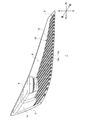
図1は、実施の形態に係る車両用灯具の斜視図である。車両用灯具1は、例えば車両前方に配置されるヘッドランプである。本実施の形態では説明の便宜上、灯具前後方向と車両用灯具1が搭載される車体の前後方向とを同一の方向とし、灯具左右方向を車体の車幅方向と同一の方向とする。
FIG. 1 is a perspective view of a vehicle lamp according to the embodiment. The
車両用灯具1は、灯具前方に開口を有するランプボディ2と、ランプボディ2の開口を覆う透光性のアウターカバー(図示せず)と、を備える。ランプボディ2とアウターカバーとで形成される灯室4内には、灯具ユニット6と、導光体8と、複数の光源10(図2参照)と、光源制御部12と、エクステンション部材14と、が収容される。灯具ユニット6、導光体8、複数の光源10、光源制御部12およびエクステンション部材14は、それぞれ図示しない支持機構を介してランプボディ2に固定される。
The
灯具ユニット6は、公知の構造を有し、ロービーム用配光パターンやハイビーム用配光パターン等を形成することができる。導光体8は板状であり、一例として灯室4の底面に配置される。導光体8は、灯具前後方向および車幅方向に拡がるように姿勢が定められている。灯具ユニット6は、導光体8の上方に配置されている。複数の光源10は、導光体8の灯具後方側に配置される。光源制御部12は、複数の光源10の点消灯を制御する。なお、光源制御部12は、灯室4の外部に設けられてもよい。エクステンション部材14は、車両用灯具1の内部構造を灯具外部から見えないようにするための目隠し用の部材であり、主にランプボディ2と灯具ユニット6との間に設けられる。
The lamp unit 6 has a known structure and can form a low beam light distribution pattern, a high beam light distribution pattern, and the like. The
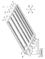
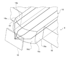
図2は、導光体8の一部と複数の光源10の一部との斜視図である。図3は、図2における任意の1つの光源10を含む領域の拡大図である。図2では、光源制御部12を機能ブロックとして描いている。この機能ブロックは、ハードウェア構成としてはコンピュータのCPUやメモリをはじめとする素子や回路で実現され、ソフトウェア構成としてはコンピュータプログラム等によって実現される。この機能ブロックがハードウェア、ソフトウェアの組合せによっていろいろなかたちで実現できることは、当業者には理解されるところである。
FIG. 2 is a perspective view of a part of the
導光体8は、透光性を有する樹脂部材である。導光体8は、複数の第1部分16、および第2部分18を有する。各第1部分16は、棒状であり互いの第1周面16aどうしが対向するように配列される。周面とは、棒状部材の延伸軸に沿って延びる表面である。各第1部分16は、その延伸軸が灯具前後方向に延びるように姿勢が定められて車幅方向に配列されている。複数の第1部分16は、互いに平行に延びる。
The
本実施の形態の各第1部分16は、角柱状であり、一対の第1周面16a、第2周面16bおよび第3周面16cを有する。各周面はそれぞれ平面状である。一対の第1周面16aは、車幅方向に並んで互いに対向するとともに、互いに平行に延びる。そして、隣り合う第1部分16の第1周面16aどうしが対向する。第2周面16bおよび第3周面16cは、互いに対向するとともに、それぞれが一対の第1周面16aをつなぐ。したがって、各第1部分16の延伸軸と直交する断面の形状は、一対の第1周面16a、第2周面16bおよび第3周面16cが各片を構成する四角形状である。
Each
また、各第1部分16は、第1端面16dおよび第2端面16eを有する。端面とは、棒状部材の端部において延伸軸と交わる方向に延びる表面である。第1端面16dは、第1部分16の一端側において一対の第1周面16a、第2周面16bおよび第3周面16cに接続される。第2端面16eは、第1部分16の他端側において一対の第1周面16a、第2周面16bおよび第3周面16cに接続される。
In addition, each
第2部分18は、隣り合う第1部分16の第1周面16aどうしを接続する。本実施の形態の導光体8は、3本以上の第1部分16を有する。したがって、導光体8は、複数の第2部分18を有する。各第2部分18は、第1部分16の延びる方向に長尺の板状または棒状である。
The
複数の第1部分16は、第1透光材料で構成される。複数の第2部分18は、第1透光材料とは屈折率の異なる第2透光材料で構成される。例えば、第1透光材料は、ポリカーボネート(PC)である。また、第2透光材料は、ポリメタクリル酸メチル(PMMA)等のアクリル樹脂である。本実施の形態において、複数の第1部分16と複数の第2部分18とは一体成形品である。このような一体成形品は、第1透光材料と第2透光材料とを用いた公知の2色成形等により製造することができる。
The plurality of
複数の光源10はそれぞれ、例えばLED(発光ダイオード)である。なお、各光源10は、LD(レーザーダイオード)、有機または無機EL(エレクトロルミネセンス)等の他の半導体発光素子や、白熱球、ハロゲンランプ、放電球等であってもよい。複数の光源10は、複数の第1部分16それぞれの第1端面16dと対向するように配置される。各光源10は、その発光面が第1端面16dと対向するように配置される。したがって、各光源10から出射される光は、第1端面16dから各第1部分16に入射する。第1部分16に入射した光は、第1部分16の内部を第2端面16eに向けて直進するか、第1部分16の内部を内面反射しながら第2端面16eに向けて進む。
Each of the plurality of
複数の第1部分16はそれぞれ、光反射要素20を有する。光反射要素20は、第1部分16の内部を進む光を第2周面16bに向けて反射する光学要素である。本実施の形態の光反射要素20は、第2周面16bと対向する第3周面16cに設けられる複数の反射ステップで構成される。複数の反射ステップは、第3周面16cの延びる方向に配列されている。第2周面16bは、第1部分16の周面のうち第2部分18に非接続の領域である。
Each of the plurality of
したがって、各第1部分16は、第1端面16dから入射される光源10の光を内部で導光しながら、光反射要素20によって第2周面16bから光を出射する。また、本実施の形態の各第1部分16は、内部を進んで第1端面16dとは反対側の第2端面16eに到達した光を第2端面16eから出射する。
Therefore, each
図1に示すように、複数の第1部分16は、第2端面16eが灯具前方から視認され、第2周面16bが灯具上方から視認されるように配置される。よって、各第1部分16の第2周面16bと第2端面16eとが発光部として灯具外部から視認される。なお、第2端面16eは、灯具前方からの視線を斜め上方や斜め側方にずらしても視認することができ。第2周面16bは、鉛直方向上方からの視線を斜め側方や斜め前方にずらしても視認することができる。導光体8は、灯具前後方向および鉛直方向に拡がるように姿勢が定められて、第2周面16bが灯具側方から視認できるように配置されてもよい。
As shown in FIG. 1, the plurality of
第1部分16と第2部分18とは、互いに屈折率の異なる第1,2透光材料で構成されている。このため、第1部分16の内部を進む光を第1周面16aにおいて全反射させることができる。つまり、第1部分16を構成する第1透光材料と第2部分18を構成する第2透光材料との屈折率の違いを利用して、光源10の光が第2部分18側に進入することを抑制することができる。これにより、点灯させた光源10に対応する第1部分16の第2周面16bおよび第2端面16eのみを発光させることができる。
The
また、本実施の形態の第1端面16dは、対向する光源10に向かって突出する凸形状を有する。これにより、第1部分16の内部を進行する光の第2部分18に対する入射角が臨界角以上となるように、第1部分16に入射する光の進行方向を調整することができる。一例として、第1端面16dの凸形状は、第1端面16dを通過する光源10の光を平行光に変換するように設計される。これにより、第1部分16の内部を進む光が第1周面16aから第2部分18側に進入することをより確実に抑制することができる。
Further, the
導光体8は、複数の第1部分16と複数の第2部分18とが車幅方向に交互に配列された構造を有する。したがって、全ての光源10を点灯させた場合、複数のライン状の発光部が車幅方向に配列された発光パターンが形成される。
The
光源制御部12は、複数の光源10を順次点灯させる。例えば、光源制御部12は、車幅方向内側から車幅方向外側へと順番に連続して光源10を点灯させる。これにより、いわゆるシーケンシャル点灯を実現することができる。なお、光源制御部12は、新たに光源10を点灯させる際に、既に点灯している光源10の点灯を維持することもできるし、消灯することもできる。既に点灯している光源10の点灯が維持される場合には、発光部が徐々に増える発光パターンが得られる。既に点灯している光源10が消灯される場合には、発光部が徐々に移動する発光パターンが得られる。
The light
車両用灯具1は、各光源10の点灯によって各第1部分16から光を出射することで、例えばターンシグナルランプ、クリアランスランプ、デイタイムランニングランプ、ポジションランプ等として機能することができる。
The
以上説明したように、本実施の形態に係る車両用灯具1は、棒状であり互いの第1周面16aどうしが対向するように配列される複数の第1部分16、および隣り合う第1部分16の第1周面16aどうしを接続する第2部分18を有する導光体8と、複数の第1部分16それぞれの第1端面16dと対向するように配置されて、第1端面16dから各第1部分16に光を入射する複数の光源10と、を備える。複数の第1部分16は第1透光材料で構成され、第2部分18は第1透光材料とは屈折率の異なる第2透光材料で構成される。複数の第1部分16はそれぞれ光反射要素20を有し、第1端面16dから入射される光源10の光を内部で導光しながら光反射要素20によって第2部分18に非接続の第2周面16bから光を出射する。
As described above, the
導光体8は、複数の第1部分16と第2部分18とが連結された構造を有する。このため、複数の独立した導光体を車両用灯具1に搭載する場合に比べて、車両用灯具1の部品点数の増加を抑制することができる。これにより、車両用灯具1の組み立て工程の複雑化、組み立て工数の増加、コストの増加等を回避することができる。また、第1部分16と第2部分18とを屈折率の異なる透光材料で構成している。これにより、第1部分16に入射した光が第1周面16aから第2部分18側に漏れ出ることを抑制することができる。したがって、各光源10の点消灯を個別に切り替えて各第1部分16を個別に発光させる場合に、鮮明なライン状の発光部を含む発光パターンを形成することができる。
The
第1部分16から第2部分18への光の漏れを防いで鮮明なライン状の発光部を形成する方法としては、第2部分18を透光性を有しない材料で構成することが考えられる。しかしながら、この場合は、複数の光源10が非点灯のときも第1部分16と第2部分18とを視覚的に区別することが容易である。このため、複数の光源10の点灯時と非点灯時とで導光体8の見た目の変化が小さい。
As a method of preventing light from leaking from the
これに対し、第1部分16および第2部分18をともに透光材料で構成することで、複数の光源10が非点灯のときは1枚の透明な板として視認され、光源10が点灯した際には透明な板にライン状の発光部が鮮明に浮かび上がって見える意匠を実現することができる。これにより、車両用灯具1の誘目性をより高めることができる。また、車両用灯具1の意匠性、見栄えを向上させることができる。
On the other hand, by forming both the
なお、第2部分18は光反射要素20を有しない。このため、第2部分18に入射した光は、第2部分18から導光体8の外部に出射されないか、出射されたとしても無視できる程度である可能性もある。しかしながら、第2部分18に光が入射すると、この光が第2部分18を通過して隣接する第1部分16に入射し、この第1部分16から導光体8の外部に出射されてしまう。所定の第1部分16は発光させ、これに隣接する第1部分16は発光させないという発光パターンを形成しようとした場合、第2部分18を経由して隣接する第1部分16からも光が出射されてしまうと、発光パターンが不鮮明になってしまう。これに対し、本実施の形態によれば、第1部分16から第2部分18への光の漏れを抑制することができるため、鮮明な発光パターンを形成することができる。
The
また、本実施の形態では、複数の第1部分16と第2部分18とは一体成形品である。これにより、導光体8の取り扱いが容易になり、車両用灯具1の組み立て工程をより簡略化することができる。
Further, in the present embodiment, the plurality of
また、本実施の形態の車両用灯具1は、複数の光源10を順次点灯させる光源制御部12を有する。上述の導光体8の各第1部分16に各光源10の光を順番に入射させることで、鮮明なライン状の発光部が徐々に増加したり、当該発光部が徐々に移動したりする発光態様を実現することができる。また、本実施の形態において、複数の第1部分は互いに平行に延びる。これにより、車両用灯具1の誘目性をより高めることができる。また、車両用灯具1の意匠性、見栄えを向上させることができる。
Further, the
また、本実施の形態の複数の第1部分16はそれぞれ、第1端面16dとは反対側の第2端面16eからも光を出射する。さらに、複数の第1部分16は、第2端面16eが灯具前方から視認され、第2周面16bが灯具上方または灯具側方から視認されるように配置される。これらにより、発光部を灯具外部から視認することができる角度範囲を拡げることができる。この結果、車両用灯具1の被視認性を高めることができ、運転者や歩行者等の安全性を高めることができる。
Further, each of the plurality of
また、本実施の形態の第1端面16dは、光源10に向かって突出する凸形状を有する。これにより、第1部分16から第2部分18への光の漏れをより確実に抑制することができる。よって、鮮明な発光パターンをより確実に形成することができる。
Further, the
また、本実施の形態の光反射要素20は、第2周面16bと対向する第3周面16cに設けられる反射ステップで構成される。これにより、第1部分16の内部を進む光をより確実に第3周面16cから出射させることができる。この結果、第1部分16から第2部分18への光の漏れをより確実に抑制することができ、鮮明な発光パターンをより確実に形成することができる。
Further, the
以上、本発明の実施の形態について詳細に説明した。前述した実施の形態は、本発明を実施するにあたっての具体例を示したものにすぎない。実施の形態の内容は、本発明の技術的範囲を限定するものではなく、請求の範囲に規定された発明の思想を逸脱しない範囲において、構成要素の変更、追加、削除等の多くの設計変更が可能である。設計変更が加えられた新たな実施の形態は、組み合わされる実施の形態および変形それぞれの効果をあわせもつ。前述の実施の形態では、このような設計変更が可能な内容に関して、「本実施の形態の」、「本実施の形態では」等の表記を付して強調しているが、そのような表記のない内容でも設計変更が許容される。以上の構成要素の任意の組み合わせも、本発明の態様として有効である。図面の断面に付したハッチングは、ハッチングを付した対象の材質を限定するものではない。 The embodiments of the present invention have been described in detail above. The above-described embodiment merely shows a specific example in carrying out the present invention. The content of the embodiment does not limit the technical scope of the present invention, and many design changes such as modification, addition, and deletion of components are made without departing from the idea of the invention defined in the claims. Is possible. The new embodiment with the design change has the effects of the combined embodiment and the modification. In the above-described embodiment, the contents that can be changed in design are emphasized by adding notations such as "in the present embodiment" and "in the present embodiment". Design changes are allowed even if there is no content. Any combination of the above components is also valid as an aspect of the present invention. The hatching attached to the cross section of the drawing does not limit the material of the object to which the hatching is attached.
(変形例1)
図4は、変形例1に係る導光体8の斜視図である。変形例1に係る導光体8は、第1部分16の第1端面16dが灯具後方側、第1部分16の第2端面16eが灯具前方側に位置するように姿勢が定められる。また、導光体8は、第1屈曲部22を有する。導光体8は、第1屈曲部22を有することで、灯具後方側の端部が斜め下方を向き、灯具前方側の端部が灯具前方を向くように折れ曲がっている。導光体8は、灯具後方側の端部から第1屈曲部22までは、灯具前方側に向かうにつれて鉛直方向上方に位置するように斜めに延び、第1屈曲部22から灯具前方側の端部までは水平に延びる。導光体8がこのような形状を有することで、導光体8の配置の自由度を高めることができる。
(Modification example 1)
FIG. 4 is a perspective view of the
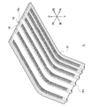
(変形例2)
図5は、変形例2に係る導光体8の平面図である。変形例2に係る導光体8は、第1部分16の第1端面16dが灯具後方側、第1部分16の第2端面16eが灯具前方側に位置するように姿勢が定められる。また、導光体8は、第2屈曲部24を有する。導光体8は、第2屈曲部24を有することで、灯具後方側の端部が斜め側方を向き、灯具前方側の端部が灯具前方を向くように折れ曲がっている。導光体8は、灯具後方側の端部から第2屈曲部24までは、灯具前方側に向かうにつれて車幅方向外側に位置するように斜めに延び、第2屈曲部24から灯具前方側の端部までは灯具前後方向に対し平行に延びる。導光体8がこのような形状を有することで、導光体8の配置の自由度を高めることができる。
(Modification 2)
FIG. 5 is a plan view of the
(その他)
光反射要素20は、第1部分16に散在する光拡散材で構成されてもよい。ただし、光反射要素20を反射ステップで構成する方が、第1部分16から第2部分18への光の漏れをより確実に抑制することができる。第1部分16が2つ以上であれば、第1部分16および第2部分18の数は特に限定されない。第1部分16および/または光反射要素20の配置や形状等を調整することで、発光パターンの形状を変更することができる。また、導光体8の姿勢は、任意に定めることができる。
(Other)
The
車両用灯具1は、車両後方に配置されるリアコンビネーションランプ等であってもよい。この場合、車両用灯具1は、各光源10の点灯によって各第1部分16から光を出射することで、例えばストップランプ、テールランプ、ターンシグナルランプ、クリアランスランプ、デイタイムランニングランプ、ポジションランプ等として機能することができる。
The
1 車両用灯具、 8 導光体、 10 光源、 12 光源制御部、 16 第1部分、 16a 第1周面、 16b 第2周面、 16c 第3周面、 16d 第1端面、 16e 第2端面、 18 第2部分、 20 光反射要素。 1 Vehicle lamp, 8 Light guide, 10 Light source, 12 Light source control unit, 16 1st part, 16a 1st peripheral surface, 16b 2nd peripheral surface, 16c 3rd peripheral surface, 16d 1st end surface, 16e 2nd end surface , 18 Second part, 20 Light reflecting element.
Claims (8)
前記複数の第1部分それぞれの第1端面と対向するように配置されて、前記第1端面から各第1部分に光を入射する複数の光源と、を備え、
前記複数の第1部分は第1透光材料で構成され、前記第2部分は前記第1透光材料とは屈折率の異なる第2透光材料で構成され、
前記複数の第1部分はそれぞれ光反射要素を有し、前記第1端面から入射される前記光源の光を内部で導光しながら前記光反射要素によって前記第2部分に非接続の第2周面から光を出射することを特徴とする車両用灯具。 A light guide body having a plurality of first portions that are rod-shaped and arranged so that their first peripheral surfaces face each other, and a second portion that connects the first peripheral surfaces of the adjacent first portions. ,
A plurality of light sources arranged so as to face the first end surface of each of the plurality of first portions and incident light from the first end surface to each first portion are provided.
The plurality of first portions are composed of a first translucent material, and the second portion is composed of a second translucent material having a refractive index different from that of the first translucent material.
Each of the plurality of first portions has a light reflecting element, and while guiding the light of the light source incident from the first end surface internally, the second circumference is not connected to the second portion by the light reflecting element. A vehicle lighting fixture that emits light from a surface.
Priority Applications (1)
| Application Number | Priority Date | Filing Date | Title |
|---|---|---|---|
| JP2019079831A JP2020177832A (en) | 2019-04-19 | 2019-04-19 | Vehicle lighting |
Applications Claiming Priority (1)
| Application Number | Priority Date | Filing Date | Title |
|---|---|---|---|
| JP2019079831A JP2020177832A (en) | 2019-04-19 | 2019-04-19 | Vehicle lighting |
Publications (1)
| Publication Number | Publication Date |
|---|---|
| JP2020177832A true JP2020177832A (en) | 2020-10-29 |
Family
ID=72935809
Family Applications (1)
| Application Number | Title | Priority Date | Filing Date |
|---|---|---|---|
| JP2019079831A Pending JP2020177832A (en) | 2019-04-19 | 2019-04-19 | Vehicle lighting |
Country Status (1)
| Country | Link |
|---|---|
| JP (1) | JP2020177832A (en) |
Cited By (1)
| Publication number | Priority date | Publication date | Assignee | Title |
|---|---|---|---|---|
| JP2023079918A (en) * | 2021-11-29 | 2023-06-08 | 市光工業株式会社 | Vehicular lighting fixture |
-
2019
- 2019-04-19 JP JP2019079831A patent/JP2020177832A/en active Pending
Cited By (2)
| Publication number | Priority date | Publication date | Assignee | Title |
|---|---|---|---|---|
| JP2023079918A (en) * | 2021-11-29 | 2023-06-08 | 市光工業株式会社 | Vehicular lighting fixture |
| JP7735823B2 (en) | 2021-11-29 | 2025-09-09 | 市光工業株式会社 | Vehicle lighting fixtures |
Similar Documents
| Publication | Publication Date | Title |
|---|---|---|
| JP4930787B2 (en) | VEHICLE LIGHT AND LIGHT GUIDE LENS USED FOR VEHICLE LIGHT | |
| EP2990720B1 (en) | Vehicle lighting unit | |
| JP7081977B2 (en) | Vehicle lighting | |
| JP6278510B2 (en) | Vehicle lighting | |
| JP2014203712A (en) | Vehicular direction indicator | |
| JPWO2018074242A1 (en) | Vehicle lighting | |
| CN106066020A (en) | Auto lamp | |
| KR20030015865A (en) | Vehicle lamp | |
| JP6413717B2 (en) | Vehicle lighting | |
| JP2012064533A (en) | Lamp fitting for vehicle | |
| JP6975571B2 (en) | Vehicle lighting | |
| JP2016527685A (en) | Illumination system, in particular for automotive lighting components, comprising a printed circuit board in the plane of illumination direction | |
| JP6762979B2 (en) | Vehicle lighting | |
| WO2016104111A1 (en) | Vehicular lighting tool | |
| JP2014038733A (en) | Lamp for vehicle | |
| JP7205193B2 (en) | vehicle lamp | |
| JP6546768B2 (en) | Vehicle light guide, vehicle lamp | |
| JP2020009656A (en) | Vehicle lighting | |
| JP2015008111A (en) | Composite lamp unit using linear light guide body, and vehicular lighting device | |
| JP7557337B2 (en) | Vehicle lighting fixtures | |
| CN210219614U (en) | Vehicle lamps | |
| JP6221438B2 (en) | Vehicle lighting | |
| JP7689884B2 (en) | Vehicle lighting fixtures | |
| WO2024034558A1 (en) | Vehicle lamp | |
| JP2016207348A (en) | Light guide body for vehicle, lighting fixture for vehicle |