JP2020179902A - Volatilization container - Google Patents
Volatilization container Download PDFInfo
- Publication number
- JP2020179902A JP2020179902A JP2019085257A JP2019085257A JP2020179902A JP 2020179902 A JP2020179902 A JP 2020179902A JP 2019085257 A JP2019085257 A JP 2019085257A JP 2019085257 A JP2019085257 A JP 2019085257A JP 2020179902 A JP2020179902 A JP 2020179902A
- Authority
- JP
- Japan
- Prior art keywords
- volatilization
- container
- side wall
- deformed
- liquid
- Prior art date
- Legal status (The legal status is an assumption and is not a legal conclusion. Google has not performed a legal analysis and makes no representation as to the accuracy of the status listed.)
- Granted
Links
Images




Landscapes
- Packaging Of Annular Or Rod-Shaped Articles, Wearing Apparel, Cassettes, Or The Like (AREA)
- Disinfection, Sterilisation Or Deodorisation Of Air (AREA)
- Catching Or Destruction (AREA)
Abstract
【課題】 従来よりも少ない部分点数で揮散量の調整を可能とする揮散容器を創出することを課題とする。【解決手段】 揮散液Pを収容する容器本体2と、容器本体2の口筒部2aに装着される装着筒10と、装着筒10から容器本体2内に垂下設されて揮散液Pを吸い上げる吸上げ芯3と、吸上げ芯3によって吸い上げられた揮散液Pを揮散させる揮散部材4と、容器本体2に装着されるキャップ本体20とを有する揮散容器であって、キャップ本体20は、揮散孔23が形成された頂壁21及び側壁22を有し、側壁22には、その一部を容器軸O方向に変形可能に形成された変形部25と、変形部25の変形状態を維持することにより、揮散液Pが外部に揮散される揮散開口Qを形成する係止部27b,28bが一体に形成された構成とする。【選択図】 図3An object of the present invention is to create a volatilization container that enables adjustment of the volatilization amount with a smaller number of parts than conventional ones. SOLUTION: A container main body 2 for containing a volatilized liquid P, a mounting cylinder 10 mounted on a mouth cylinder part 2a of the container main body 2, and a volatilized liquid P sucked up by hanging down from the mounting cylinder 10 into the container main body 2. A volatilization container having a suction core 3, a volatilization member 4 for volatilizing the volatilization liquid P sucked up by the suction core 3, and a cap body 20 attached to the container body 2, wherein the cap body 20 is a volatilization It has a top wall 21 with a hole 23 formed therein and a side wall 22. The side wall 22 has a deformable portion 25 partially deformable in the direction of the container axis O, and the deformed state of the deformable portion 25 is maintained. As a result, the locking portions 27b and 28b forming the volatilization openings Q through which the volatilization liquid P volatilizes to the outside are integrally formed. [Selection drawing] Fig. 3
Description
本発明は、揮散量を調整し得る揮散容器に関する。 The present invention relates to a volatilization container in which the amount of volatilization can be adjusted.
特許文献1に記載の揮散容器は、容器体口頸部12の上端開口を閉塞する頂板部21に穿設した吸上げ芯貫通用の窓孔22に上端部を嵌着し、下端部を容器体A内に垂下させた吸上げ芯B2と、吸上げ芯B2からの液を揮散窓より揮散する吸上げ芯B2上の揮散板B3とを備えて構成されており、キャップ本体B1に対して揮散窓42が形成された蓋体B4を上方へスライドさせて揮散窓42の開口面積を可変することにより、揮散量を調整することが可能となっている。
In the volatilization container described in
上記特許文献1に記載された揮散容器において揮散量を調整するには、キャップ本体B1と揮散窓42を備えた蓋体B4とを別々に形成する必要があった。
しかし、近年においては部品点数の削減によるコスト軽減の促進が求められており、そのためには従来よりも更に部分点数の少ない構成で揮散量の調整を可能とする揮散容器の開発が求められている。
In order to adjust the amount of volatilization in the volatilization container described in
However, in recent years, it has been required to promote cost reduction by reducing the number of parts, and for that purpose, it is required to develop a volatilization container capable of adjusting the amount of volatilization with a configuration having a smaller number of partial points than before. ..
本発明は、上記した従来技術における問題点を解消すべく、従来よりも少ない部分点数で揮散量の調整を可能とする揮散容器を創出することを課題とする。 An object of the present invention is to create a volatilization container capable of adjusting the volatilization amount with a smaller number of partial points than in the prior art in order to solve the above-mentioned problems in the prior art.
上記課題を解決するための手段のうち、本発明の主たる手段は、
揮散液を収容する容器本体と、容器本体の口筒部に装着される装着筒と、装着筒から容器本体内に垂下設されて揮散液を吸い上げる吸上げ芯と、吸上げ芯によって吸い上げられた揮散液を揮散させる揮散部材と、容器本体に装着されるキャップ本体とを有する揮散容器であって、
キャップ本体は、揮散孔が形成された頂壁及び側壁を有し、側壁には、その一部を容器軸方向に変形可能に形成された変形部と、変形部の変形状態を維持することにより、揮散液が外部に揮散される揮散開口を形成する係止部が一体に形成されていることを特徴とする、と云うものである。
Among the means for solving the above problems, the main means of the present invention is
The container body that houses the volatilized liquid, the mounting cylinder that is attached to the mouthpiece of the container body, the suction core that hangs down from the mounting cylinder into the container body and sucks up the volatilized liquid, and the suction core. A volatilization container having a volatilization member for volatilizing the volatilization liquid and a cap body attached to the container body.
The cap body has a top wall and a side wall in which a volatilization hole is formed, and the side wall has a deformed portion formed so that a part thereof can be deformed in the direction of the container axis and a deformed state of the deformed portion is maintained. It is said that the locking portion forming the volatilization opening through which the volatilization liquid is volatilized to the outside is integrally formed.
本発明の主たる手段では、側壁に設けられた変形部を押圧すると、変形部が陥没状態に設定されて大きな揮散開口が形成され、揮散液をこの揮散開口を介して揮散させることが可能となるため、揮散量を増大させることができる。 In the main means of the present invention, when the deformed portion provided on the side wall is pressed, the deformed portion is set in a depressed state to form a large volatilization opening, and the volatilization liquid can be volatilized through the volatilization opening. Therefore, the amount of volatilization can be increased.
本発明の他の手段は、主たる手段に、変形部が、少なくとも揮散部材の外周面よりも内側の位置まで変形可能に構成されている、との手段を加えたものである。 The other means of the present invention is obtained by adding a means that the deformable portion is configured to be deformable at least to a position inside the outer peripheral surface of the volatilizing member, in addition to the main means.
上記手段では、揮散部材の外周面側の下面が、変形部が陥没変形することよって形成された揮散開口に対向配置することになり、この揮散開口を通じての揮散を容易とすること、特にキャップ本体の内側に留まっている気化状態の揮散液を外部に容易に揮散させることが可能となるため、揮散量を増大させることができる。 In the above means, the lower surface of the volatilization member on the outer peripheral surface side is arranged to face the volatilization opening formed by the depressed deformation of the deformed portion, facilitating volatilization through the volatilization opening, particularly the cap body. Since the vaporized liquid in the vaporized state can be easily volatilized to the outside, the amount of volatilization can be increased.
本発明の他の手段は、上記手段に、キャップ本体は、前側壁及び後側壁に、その一部を変形させる変形部が設けられ、前側壁及び後側壁に対して直交する位置に設けられた右側壁及び左側壁が、変形部を変形前の初期形状に復元させる係止解除機能を備える、と云うものである。
上記手段では、右側壁及び左側壁を押圧すると、係止部による変形部の係止が解除されて変形部が変形前の初期形状に復元するため、揮散量を元の初期状態まで減少させることができる。このため、前側壁及び後側壁に対する押圧操作による変形部の係止と、右側壁及び左側壁に対する押圧操作による変形部の係止解除を選択して行うことにより、揮散量を調整することが可能となる。
In the other means of the present invention, the cap body is provided with deformed portions on the front side wall and the rear side wall for deforming a part thereof, and is provided at a position orthogonal to the front side wall and the rear side wall. It is said that the right side wall and the left wall have an unlocking function for restoring the deformed portion to the initial shape before deformation.
In the above means, when the right wall and the left wall are pressed, the deformed portion is released from the locking portion and the deformed portion is restored to the initial shape before deformation, so that the amount of volatilization is reduced to the original initial state. Can be done. Therefore, the amount of volatilization can be adjusted by selectively locking the deformed portion by pressing the front side wall and the rear side wall and unlocking the deformed portion by pressing the right side wall and the left side wall. It becomes.
本発明の他の手段は、変形部を変形前の初期形状に復元させる係止解除機能として、一端に指掛け部が形成され、他端に変形部を押圧して係止部による係止を解除する押圧部が形成されて揺動可能に設けられた揺動部材を備える、と云うものである。
上記手段では、揺動部材を操作すると、係止部による変形部の係止が容易に解除されて変形部が変形前の初期形状に復元するため、揮散量を元の初期状態まで減少させることができる。このため、押圧操作による変形部の係止と、揺動部材による変形部の係止解除とを選択して行うことにより、揮散量を調整することが可能となる。
Another means of the present invention is a locking release function for restoring the deformed portion to the initial shape before deformation, in which a finger hook portion is formed at one end and the deformed portion is pressed at the other end to release the locking by the locking portion. It is said that a swinging member is provided so that a pressing portion is formed and swingable.
In the above means, when the rocking member is operated, the deformed portion is easily unlocked by the locking portion and the deformed portion is restored to the initial shape before deformation, so that the amount of volatilization is reduced to the original initial state. Can be done. Therefore, it is possible to adjust the amount of volatilization by selectively locking the deformed portion by the pressing operation and unlocking the deformed portion by the swinging member.
本発明の揮散容器では、揮散開口を形成するための変形部をキャップ本体に一体的に形成することができるため、従来よりも少ない部分点数で揮散量を調整することができる。 In the volatilization container of the present invention, since the deformed portion for forming the volatilization opening can be integrally formed on the cap body, the volatilization amount can be adjusted with a smaller number of partial points than before.
以下、本発明の実施の形態について図面を参照しつつ説明する。
本発明の揮散容器は、例えば芳香剤、消臭剤又は防虫忌避剤等の揮散性の液体(以下、揮散液Pという)を収容して室内や車内などの空気雰囲気中に揮散させるための容器である。
Hereinafter, embodiments of the present invention will be described with reference to the drawings.
The volatilization container of the present invention is a container for containing a volatilizing liquid (hereinafter referred to as volatilization liquid P) such as an air freshener, a deodorant or an insect repellent and volatilizing it in an air atmosphere such as indoors or a car. Is.
本発明の第1実施例の揮散容器について図1乃至図4を用いて説明する。
揮散容器1は、揮散液Pが収容される容器本体2と、揮散液Pを吸い上げる棒状の吸上げ芯3と、吸上げ芯3が吸い上げた揮散液Pを気化させて容器本体2の外部に向けて揮散させる揮散部材4と、吸上げ芯5を保持してその下端を容器本体2内の揮散液P中に含浸させる装着筒10と、容器本体2にオーバーキャップ状に装着されてなるキャップ本体20とを有して構成されている。尚、容器本体2、装着筒10及びキャップ本体20は夫々合成樹脂材料で形成されている。
The volatilization container of the first embodiment of the present invention will be described with reference to FIGS. 1 to 4.
The
容器本体2は、有底筒状の胴部2cの上に縮径状に形成されてなる肩部2bを介して外周面に雄ネジが刻設された口筒部2aが立設する構成である。本実施例では胴部2cが平面視略楕円形状の容器本体2であるが、容器本体2の形状はこれに限られるものではない。
容器本体2の口筒部2aには装着筒10が装着され、その上からネジキャップ式の蓋体30が螺着されることによって被嵌されている。尚、蓋体30は揮散容器1の使用を開始する際に口筒部2aから取り外される。
The
A
装着筒10は、円環状のフランジ11の下面の外側にインナーシール部12を有し、その内側にすり鉢状のテーパー部13が形成され、その下端には下方に向かって延びる長筒部14が一体に延設されている。尚、テーパー部13には空気置換用の貫通孔15が形成されている。
装着筒10は、フランジ11の下面を口筒部2aの上面に載置し、インナーシール部12を口筒部2aの内周面に密着させ、更にテーパー部13及び長筒部14を容器本体2の底部(図示せず)方向に向かって垂下設させた状態で装着されている。
The
In the
吸上げ芯3は、例えばフェルト、合成繊維束、天然繊維束、発泡合成樹脂などの多孔質素材からなる棒状の部材で形成されており、テーパー部13及び長筒部14の内側に挿入された状態で保持されている。吸上げ芯3の上端はフランジ11よりも上方に突出しており、後述する揮散部材4の下面に接触可能に構成されている。また吸上げ芯3の下端は容器本体2の底部に達しており、容器本体2内に充填されている揮散液Pを吸い上げることが可能となっている。
The suction core 3 is formed of a rod-shaped member made of a porous material such as felt, a synthetic fiber bundle, a natural fiber bundle, or a foamed synthetic resin, and is inserted inside the
揮散部材4は、例えば天然紙、合成紙などの紙類、又はフェルト、合成繊維束、天然繊維束、発泡合成樹脂などの多孔質素材によって、厚く且つ広い面積を有し、全体としても広い表面積を備える形状で形成されており、吸上げ芯3が吸い上げた揮散液Pを含浸した状態で空気雰囲気中に効率良く揮散することが可能となっている。
The volatilizing
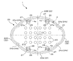
図2に示すように、キャップ本体20は、底部側が開放された有頂筒状(オーバーキャップ状)に構成され、平面視略楕円形状に形成された頂壁21と短軸側の側壁22である前側壁22A及び後側壁22Bには複数の揮散孔23が形成されている。
また短軸側に設けられた前側壁22A、後側壁22B及び長軸側に設けられた右側壁22C、左側壁22Dには、上下に所定の間隔を有して周方向に平行に且つ間欠的に延びる一対の長孔24A、長孔24Bが形成されている。上側の長孔24Aの周方向の4箇所の位置には柱部24aが夫々形成され、同様に下側の長孔24Bの周方向の4箇所の位置にも柱部24bが夫々形成されている。そして、前側壁22A及び後側壁22B内の一部の領域、すなわち上側の長孔24Aに設けられた2つの柱部24aと下側の長孔24Bに設けられた2つの柱部24bとによって挟まれる領域に略長方形状から成る変形部25が設けられている。この変形部25は、前側壁22A又は後側壁22Bにおいて、上側左右に設けられた柱部24aと下側左右に設けられた柱部24bを夫々起点として、変形部25の中央部分が容器軸Oに近づく方向に向かって陥没変形可能に構成されている。このため、変形部25の中央部分を容器軸Oに近づく方向に向かって押圧すると、変形部25を陥没状態に変形させることが可能である。
As shown in FIG. 2, the
Further, the
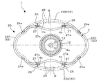
図1及び図3に示すように、長孔24Aよりも上側に位置するキャップ本体20の内側の4箇所の位置には、前側壁22A又は後側壁22Bの内面から容器軸O側に向けて夫々突出する凸壁部26が夫々一体に形成されている。各凸壁部26はキャップ本体20内に設けられた揮散部材4に形成された切欠部4a内に配置されており、各凸壁部26の容器軸O側の端部には、鉛直方向に延びる長板状の係止部材27が一体に連設されている。
As shown in FIGS. 1 and 3, four positions inside the
各支持部材27の内面には上方に向かって略J字形状に形成された支持片27aが夫々形成されており、揮散部材4の下面は4箇所の位置に設けられた各支持片27aによって支持されている。また係止部材27の下端には、変形部25の上端よりも僅かに下がった位置まで延設された係止部27bが設けられている。
尚、4箇所に設けられた支持部材27の上端と対向する頂壁21の各位置には射出成型用の開孔部28が形成されているが、この開孔部28は揮散液Pが揮散する孔としても機能する。
またキャップ本体20の側壁22の下端には、容器軸O方向に突出する係合突起22aが形成されており、容器本体2の胴部2cに形成された係合凹部2dに係合可能に構成されている。
Further, an engaging
次に上記揮散容器1の使用方法について説明する。
容器本体2に対しキャップ本体20を持ち上げると、係合突起22aと係合凹部2dとの係合が外れるため、容器本体2からキャップ本体20を取り外すことができる。この状態において、蓋体30を螺脱させて口筒部2aを被嵌していた蓋体30を取り外すことにより、吸上げ芯3の上端を露出させることができる。
Next, a method of using the
When the
あるいは初めから吸上げ芯3が装着部10に設けられていない構成の場合には、蓋体30を外した状態において、吸上げ芯3を装着部10のテーパー部13及び長筒部14内に挿入して吸上げ芯3の下端を容器本体2内の揮散液P内に沈降させる。
Alternatively, in the case where the suction core 3 is not provided in the mounting
次に、再度キャップ本体20を容器本体2の上部に装着して係合突起22aを係合凹部2dに係合させると共に、吸上げ芯3の上端面を揮散部材4の下面に接触させる。
これにより、吸上げ芯3内を浸透して上方に向かって吸い上げられた揮散液Pで揮散部材4を含浸させることができる。揮散部材4の表面から気化した揮散液Pは、キャップ本体20に形成されている複数の揮散孔23及び開孔部28を介して外部に揮散することになる。
Next, the
As a result, the
次に、前側壁22Aと後側壁22Bを片手で挟んで把持した状態において、各変形部25の中央部近傍を夫々容器軸Oに向けて押圧して陥没変形させる。すると、各変形部25の上端が係止部27bを容器軸Oに向かって乗り越える。係止部27bは、変形部25の上端の変形領域内に突出しているため、把持した手を離すと、変形部25の上端を係止部27bで係止することができる。よって、陥没変形後の変形部25が、変形前の初期の形状に復元することを阻止することができる(図3の破線及び図4参照)。この状態では、変形部25が容器軸Oに向かって大きく陥没変形する状態が維持され、この陥没変形した部分に揮散液Pが揮散するための揮散開口Qを形成することができる。このように、係止部27bは変形部25を陥没状態に維持する係止機構として機能する。
Next, in a state where the
ここで、図3及び図4に示すように変形部25は、揮散部材4の外周面よりも内側の位置まで陥没変形可能に構成されており、陥没変形した状態では、揮散部材4の外周面側の下面を、変形部25が陥没変形することよって形成された揮散開口Qに対向配置させることが可能となる。これにより、気化した揮散液Pは、この揮散開口Qを通じて容易に揮散することが可能となることから揮散量を増大させることが可能である。
Here, as shown in FIGS. 3 and 4, the
次に、変形部25が陥没変形した状態において、平面視において前側壁22Aと後側壁22Bと直交する方向に設けられた右側壁22C、左側壁22Dを容器軸Oに向けて同時に押圧すると、右側壁22C、左側壁22Dには容器軸Oから離れる方向に大きな力が作用し、変形部25が容器軸Oから離れる外方向に膨出変形する。この際、変形部25の上端が係止部27bを外方向に乗り越えるため、係止部27bによる変形部25上端の係止を容易に解除することができる。これにより、変形部25は変形前の初期形状(外側に膨らむ膨出形状)に復元し、陥没変形によって形成された揮散開口Qが閉じられるため、揮散量を変形前の初期状態まで減少させることができる。すなわち、キャップ本体20を構成する右側壁22C及び左側壁22Dは、陥没変形した変形部25を変形前の初期の形状に戻すための係止解除機能を備えている。
Next, in a state where the
このように、本発明では、キャップ本体20に設けられた変形部25を陥没変形させ又は変形前の初期形状(膨出形状)に戻すことにより、揮散液Pの揮散量を調整することが可能となっている。
As described above, in the present invention, it is possible to adjust the amount of volatilization of the volatilization liquid P by depressedly deforming the
図5乃至図9は本発明の第2実施例を示している。
第2実施例に示す揮散容器1が、上記第1実施例において説明した揮散容器1と異なる点はキャップ本体20の構成にあり、その他の構成及び効果は第1実施例同様であるため、以下においては主としてキャップ本体20を中心に説明する。尚、同一の部材について同一の符号を付するものとする。
5 to 9 show a second embodiment of the present invention.
The
図5に示すように、第2実施例に示すキャップ本体20は、頂壁21と、容器軸Oから外側に向かって膨出する湾曲面で形成された前側壁22A及び後側壁22Bと、右側壁22C及び左側壁22Dとで形成される側壁22を有して形成され、底部側が開放する有頂筒状の部材である。
頂壁21、前側壁22A及び後側壁22Bには複数の揮散孔23が形成され、更に前側壁22A及び後側壁22Bには上下方向に所定の間隔を有して水平に配置された長孔24A,24Bが形成されている。
As shown in FIG. 5, the
A plurality of volatilization holes 23 are formed in the
前側壁22A側の、長孔24Aの左端部と長孔24Bの左端部との間、及び長孔24Aの右端部と長孔24Bの右端部との間には高さ方向に沿って延びる凹条部24cが夫々形成されている。そして、上下に配置された長孔24A,24Bと左右の配置された一対の凹条部24cとによって囲まれた部分に略長方形状からなる変形部25が形成されている。そして、変形部25の中央部近傍を押圧することにより、変形部25は左右の凹条部24cを起点として、中央部分が容器軸Oに近づく方向に陥没変形することが可能となっている。
A recess extending along the height direction between the left end of the
図5及び図7に示すように、キャップ本体20を形成する頂壁21の前側壁22A側寄りの位置には開孔部28が形成されている。この開孔部28には、開孔部28の前端部分を開孔部28の内部下方に向かって垂下設させた垂下片部28aと、垂下片部28aの下端に形成された係止部28bと、係止部28bの近傍に薄肉状に形成されて成る支点部28cと、この支点部28cに連設された揺動部材29とが一体に形成されている。
As shown in FIGS. 5 and 7, an
揺動部材29は長板状又は棒状に形成され、上端に指掛け部29aが、下端に押圧部29bが設けられている。上端の指掛け部29aはキャップ本体20内に設けられた揮散部材4に形成された切欠部4aを通って開孔部28内に配置され、下端の押圧部29bは容器本体2の口筒部2aを被嵌している蓋体30の側面31に対して近接配置されており、この状態で支点部28cに対して揺動可能に支持されている。
The
第1実施例同様、第2実施例に示す揮散容器1においても、容器本体2の口筒部2aを被嵌している蓋体30を外し、吸上げ芯3の上端面を揮散部材4の下面に接触させることにより使用を開始することができる。吸上げ芯3を通じて吸い上げられて揮散部材4を含浸した揮散液Pは、揮散部材4からキャップ本体20に形成されている揮散孔23及び開孔部28を介して外部の空気雰囲気中に揮散される。
Similar to the first embodiment, in the
図8に示すように、手でキャップ本体20の前側壁22Aに設けられた変形部25を容器軸Oに向かって押圧すると、変形部25を容器軸Oに陥没変形させることができる。この際、変形部25の上端が係止部28bを内方に向かって乗り越える。係止部28bの下端は、変形部25の上端の変形領域内に突設されているため、押圧した手を離すと、変形部25の上端を係止部28bで係止することができる。よって、陥没変形後の変形部25が、変形前の初期形状(膨出形状)に復元することを阻止することができる。この係止状態では、変形部25が容器軸Oに向かって大きく陥没変形した状態が維持され、この陥没変形した部分に揮散液Pが揮散するための揮散開口Qを形成することができる。このように、係止部28bは変形部25を陥没状態に維持する係止機構として機能する。
As shown in FIG. 8, when the
図5及び図7等に示すように第2実施例の構成においても、変形部25は、揮散部材4の外周面よりも内側の位置まで陥没変形可能に構成されており、陥没変形した状態では、揮散部材4の外周面側の下面を、変形部25が陥没変形することよって形成された揮散開口Qの真上の位置に対向配置させることができることから、揮散開口Qを介して揮散する揮散液Pの揮散量を増大させることが可能である。
As shown in FIGS. 5 and 7, even in the configuration of the second embodiment, the
図9に示すように、開孔部28を通じて垂下片部28aと揺動部材29の上端である指掛け部29aとの間に指先を挿入して揺動部材29を揺動させると、揺動部材29の下端の押圧部29bで変形部25の内面を外部に向かって押し出すことができる。この際、変形部25の上端が係止部28bを外部に向かって乗り越えるため、係止部28bによる変形部25の上端の係止を容易に解除することができる。これにより、変形部25は変形前の初期形状(膨出形状)に復帰するため、揮散量を変形前の初期状態まで減少させることができる。すなわち、揺動部材29は、係止部28bによる変形部25の係止を解除する係止解除機構としての機能を備えるものである。
As shown in FIG. 9, when the
このように、第2実施例においても、キャップ本体20に設けられた変形部25を陥没変形させ又は変形前の初期形状(膨出形状)に戻すことにより、揮散開口Qを形成し又は形成した揮散開口Qを閉じることができることから、上記同様に揮散液Pの揮散量を調整することが可能である。
As described above, also in the second embodiment, the volatilization opening Q is formed or formed by the
以上、実施例に沿って本発明の構成とその作用効果について説明したが、本発明の実施の形態は上記実施例に限定されるものではない。 Although the configuration of the present invention and its action and effect have been described above with reference to Examples, the embodiments of the present invention are not limited to the above Examples.
例えば、上記実施例では、容器本体2の蓋体としてネジキャップ式の蓋体30を示して説明したが、蓋体30はこれに限られるものではなく、嵌合によって口筒部2aを被嵌するタイプのものであっても良い。
For example, in the above embodiment, the screw
また第1実施例では、変形部25を前側壁22Aと後側壁22Bの双方に設けた場合を示して説明したが、いずれか一方にのみに設ける構成であっても良い。
Further, in the first embodiment, the case where the
また第2実施例では、変形部25及び係止機構及び係止解除機構を前側壁22A側のみ設けた構成を示して説明したが、後側壁22B側にも同様の構成を設ける構成とすることで更に揮散量を増大させることが可能となる。
Further, in the second embodiment, the configuration in which the
本発明は、芳香剤や消臭剤等を揮散する揮発容器の分野における用途展開を更に広い領域で図ることができる。 The present invention can be used in a wider range of applications in the field of volatile containers that volatilize air fresheners, deodorants, and the like.
1 : 揮散容器
2 : 容器本体
2a : 口筒部
2b : 肩部
2c : 胴部
2d : 係合凹部
3 : 吸上げ芯
4 : 揮散部材
4a : 切欠部
10 : 装着筒
11 : フランジ
12 : インナーシール部
13 : テーパー部
14 : 長筒部
15 : 貫通孔
20 : キャップ本体
21 : 頂壁
22 : 側壁
22A: 前側壁
22B: 後側壁
22C: 右側壁
22D: 左側壁
22a: 係合突起
23 : 揮散孔
24A: 長孔
24B: 長孔
24a: 柱部
24b: 柱部
24c: 凹条部
25 : 変形部
26 : 凸壁部
27 : 係止部材
27a: 支持片
27b: 係止部
28 : 開孔部
28a: 垂下片部
28b: 係止部
28c: 支点部
29 : 揺動部材
29a: 指掛け部
29b: 押圧部
30 : 蓋体
31 : 側面
O : 容器軸
P : 揮散液
Q : 揮散開口
1: Volatilization container 2:
Claims (4)
キャップ本体(20)は、揮散孔(23)が形成された頂壁(21)及び側壁(22)を有し、該側壁(22)には、その一部を容器軸(O)方向に変形可能に形成された変形部(25)と、前記変形部(25)の変形状態を維持することにより、揮散液(P)が外部に揮散される揮散開口(Q)を形成する係止部(27b,28b)が一体に成形されていることを特徴とする揮散容器。 A container body (2) for accommodating the volatilized liquid (P), a mounting tube (10) mounted on the mouth tube portion (2a) of the container body (2), and the container body (10) from the mounting tube (10). A suction core (3) hanging inside the suction core (P) to suck up the volatilization liquid (P), and a volatilization member (4) for volatilizing the volatilization liquid (P) sucked up by the suction core (3). A volatilization container having a cap body (20) attached to the container body (2).
The cap body (20) has a top wall (21) and a side wall (22) in which a volatilization hole (23) is formed, and a part of the side wall (22) is deformed in the container shaft (O) direction. A locking portion (Q) that forms a volatilization opening (Q) in which the volatilization liquid (P) is volatilized to the outside by maintaining the deformed portion (25) that is possibly formed and the deformed state of the deformed portion (25). A volatilization container characterized in that 27b, 28b) are integrally molded.
Priority Applications (1)
| Application Number | Priority Date | Filing Date | Title |
|---|---|---|---|
| JP2019085257A JP7297517B2 (en) | 2019-04-26 | 2019-04-26 | volatilization container |
Applications Claiming Priority (1)
| Application Number | Priority Date | Filing Date | Title |
|---|---|---|---|
| JP2019085257A JP7297517B2 (en) | 2019-04-26 | 2019-04-26 | volatilization container |
Publications (2)
| Publication Number | Publication Date |
|---|---|
| JP2020179902A true JP2020179902A (en) | 2020-11-05 |
| JP7297517B2 JP7297517B2 (en) | 2023-06-26 |
Family
ID=73024117
Family Applications (1)
| Application Number | Title | Priority Date | Filing Date |
|---|---|---|---|
| JP2019085257A Active JP7297517B2 (en) | 2019-04-26 | 2019-04-26 | volatilization container |
Country Status (1)
| Country | Link |
|---|---|
| JP (1) | JP7297517B2 (en) |
Cited By (1)
| Publication number | Priority date | Publication date | Assignee | Title |
|---|---|---|---|---|
| KR102864015B1 (en) * | 2025-03-24 | 2025-09-24 | ㈜아로마글로바 | diffuser |
Citations (5)
| Publication number | Priority date | Publication date | Assignee | Title |
|---|---|---|---|---|
| US4621768A (en) * | 1984-10-09 | 1986-11-11 | Reckitt & Colman S.A. | Device for diffusing volatile liquids |
| US5033674A (en) * | 1990-05-23 | 1991-07-23 | Avon Products, Inc. | Fragrance dispenser |
| JP2002145307A (en) * | 2000-11-06 | 2002-05-22 | Yoshino Kogyosho Co Ltd | Lid of container |
| JP2002166985A (en) * | 2000-11-29 | 2002-06-11 | Yoshino Kogyosho Co Ltd | Cover of container |
| JP2004113604A (en) * | 2002-09-27 | 2004-04-15 | Yoshino Kogyosho Co Ltd | Vessel for discharging aroma, or the like |
-
2019
- 2019-04-26 JP JP2019085257A patent/JP7297517B2/en active Active
Patent Citations (5)
| Publication number | Priority date | Publication date | Assignee | Title |
|---|---|---|---|---|
| US4621768A (en) * | 1984-10-09 | 1986-11-11 | Reckitt & Colman S.A. | Device for diffusing volatile liquids |
| US5033674A (en) * | 1990-05-23 | 1991-07-23 | Avon Products, Inc. | Fragrance dispenser |
| JP2002145307A (en) * | 2000-11-06 | 2002-05-22 | Yoshino Kogyosho Co Ltd | Lid of container |
| JP2002166985A (en) * | 2000-11-29 | 2002-06-11 | Yoshino Kogyosho Co Ltd | Cover of container |
| JP2004113604A (en) * | 2002-09-27 | 2004-04-15 | Yoshino Kogyosho Co Ltd | Vessel for discharging aroma, or the like |
Cited By (1)
| Publication number | Priority date | Publication date | Assignee | Title |
|---|---|---|---|---|
| KR102864015B1 (en) * | 2025-03-24 | 2025-09-24 | ㈜아로마글로바 | diffuser |
Also Published As
| Publication number | Publication date |
|---|---|
| JP7297517B2 (en) | 2023-06-26 |
Similar Documents
| Publication | Publication Date | Title |
|---|---|---|
| JP7297517B2 (en) | volatilization container | |
| JP6025585B2 (en) | Volatilization equipment | |
| JP2020183245A (en) | Volatile agent container | |
| JP2010195429A (en) | Volatilization container | |
| JP4354078B2 (en) | Fragrance diffuser | |
| JP2016049988A (en) | Volatilization container | |
| JP4640809B2 (en) | Volatilization container | |
| JP6335686B2 (en) | Volatilization container | |
| JP4671670B2 (en) | Air freshener container | |
| JPH0465550U (en) | ||
| JP6086758B2 (en) | Volatilization equipment | |
| JP2020183244A (en) | Volatile agent container | |
| JP2024065496A (en) | Volatilization container | |
| JP2022049372A (en) | Volatilizer | |
| JP5969839B2 (en) | Volatilization container | |
| JP4322624B2 (en) | Volatilizer | |
| JP2007062819A (en) | Evaporation container | |
| JPS601721Y2 (en) | Containers for volatile active substances | |
| JP2576743Y2 (en) | Air freshener container | |
| JP4050134B2 (en) | Storage container | |
| JPH0244756Y2 (en) | ||
| JP6710043B2 (en) | Drug container | |
| JP2549069Y2 (en) | Air Freshener Container Lid Structure | |
| JP3719480B2 (en) | Airtight container | |
| JP2014195570A (en) | Volatilizing agent container |
Legal Events
| Date | Code | Title | Description |
|---|---|---|---|
| A521 | Request for written amendment filed |
Free format text: JAPANESE INTERMEDIATE CODE: A523 Effective date: 20200226 |
|
| A521 | Request for written amendment filed |
Free format text: JAPANESE INTERMEDIATE CODE: A821 Effective date: 20200227 |
|
| A711 | Notification of change in applicant |
Free format text: JAPANESE INTERMEDIATE CODE: A711 Effective date: 20200227 |
|
| A711 | Notification of change in applicant |
Free format text: JAPANESE INTERMEDIATE CODE: A711 Effective date: 20200910 |
|
| A521 | Request for written amendment filed |
Free format text: JAPANESE INTERMEDIATE CODE: A821 Effective date: 20200911 |
|
| A621 | Written request for application examination |
Free format text: JAPANESE INTERMEDIATE CODE: A621 Effective date: 20220124 |
|
| A521 | Request for written amendment filed |
Free format text: JAPANESE INTERMEDIATE CODE: A523 Effective date: 20220309 |
|
| RD02 | Notification of acceptance of power of attorney |
Free format text: JAPANESE INTERMEDIATE CODE: A7422 Effective date: 20220309 |
|
| A977 | Report on retrieval |
Free format text: JAPANESE INTERMEDIATE CODE: A971007 Effective date: 20221212 |
|
| A131 | Notification of reasons for refusal |
Free format text: JAPANESE INTERMEDIATE CODE: A131 Effective date: 20221220 |
|
| RD02 | Notification of acceptance of power of attorney |
Free format text: JAPANESE INTERMEDIATE CODE: A7422 Effective date: 20230106 |
|
| A521 | Request for written amendment filed |
Free format text: JAPANESE INTERMEDIATE CODE: A523 Effective date: 20230216 |
|
| TRDD | Decision of grant or rejection written | ||
| A01 | Written decision to grant a patent or to grant a registration (utility model) |
Free format text: JAPANESE INTERMEDIATE CODE: A01 Effective date: 20230516 |
|
| A61 | First payment of annual fees (during grant procedure) |
Free format text: JAPANESE INTERMEDIATE CODE: A61 Effective date: 20230614 |
|
| R150 | Certificate of patent or registration of utility model |
Ref document number: 7297517 Country of ref document: JP Free format text: JAPANESE INTERMEDIATE CODE: R150 |
|
| R250 | Receipt of annual fees |
Free format text: JAPANESE INTERMEDIATE CODE: R250 |