JP2020184871A - Stain inspection device, stain inspection method, and management method of photovoltaic power generation module - Google Patents
Stain inspection device, stain inspection method, and management method of photovoltaic power generation module Download PDFInfo
- Publication number
- JP2020184871A JP2020184871A JP2019171699A JP2019171699A JP2020184871A JP 2020184871 A JP2020184871 A JP 2020184871A JP 2019171699 A JP2019171699 A JP 2019171699A JP 2019171699 A JP2019171699 A JP 2019171699A JP 2020184871 A JP2020184871 A JP 2020184871A
- Authority
- JP
- Japan
- Prior art keywords
- receiving surface
- light receiving
- measurement
- degree
- color
- Prior art date
- Legal status (The legal status is an assumption and is not a legal conclusion. Google has not performed a legal analysis and makes no representation as to the accuracy of the status listed.)
- Granted
Links
Images
Classifications
-
- G—PHYSICS
- G01—MEASURING; TESTING
- G01J—MEASUREMENT OF INTENSITY, VELOCITY, SPECTRAL CONTENT, POLARISATION, PHASE OR PULSE CHARACTERISTICS OF INFRARED, VISIBLE OR ULTRAVIOLET LIGHT; COLORIMETRY; RADIATION PYROMETRY
- G01J3/00—Spectrometry; Spectrophotometry; Monochromators; Measuring colours
- G01J3/46—Measurement of colour; Colour measuring devices, e.g. colorimeters
-
- G—PHYSICS
- G01—MEASURING; TESTING
- G01N—INVESTIGATING OR ANALYSING MATERIALS BY DETERMINING THEIR CHEMICAL OR PHYSICAL PROPERTIES
- G01N21/00—Investigating or analysing materials by the use of optical means, i.e. using sub-millimetre waves, infrared, visible or ultraviolet light
- G01N21/17—Systems in which incident light is modified in accordance with the properties of the material investigated
- G01N21/25—Colour; Spectral properties, i.e. comparison of effect of material on the light at two or more different wavelengths or wavelength bands
- G01N21/27—Colour; Spectral properties, i.e. comparison of effect of material on the light at two or more different wavelengths or wavelength bands using photo-electric detection ; circuits for computing concentration
-
- G—PHYSICS
- G01—MEASURING; TESTING
- G01N—INVESTIGATING OR ANALYSING MATERIALS BY DETERMINING THEIR CHEMICAL OR PHYSICAL PROPERTIES
- G01N21/00—Investigating or analysing materials by the use of optical means, i.e. using sub-millimetre waves, infrared, visible or ultraviolet light
- G01N21/84—Systems specially adapted for particular applications
- G01N21/88—Investigating the presence of flaws or contamination
-
- G—PHYSICS
- G01—MEASURING; TESTING
- G01N—INVESTIGATING OR ANALYSING MATERIALS BY DETERMINING THEIR CHEMICAL OR PHYSICAL PROPERTIES
- G01N21/00—Investigating or analysing materials by the use of optical means, i.e. using sub-millimetre waves, infrared, visible or ultraviolet light
- G01N21/84—Systems specially adapted for particular applications
- G01N21/88—Investigating the presence of flaws or contamination
- G01N21/89—Investigating the presence of flaws or contamination in moving material, e.g. running paper or textiles
- G01N21/892—Investigating the presence of flaws or contamination in moving material, e.g. running paper or textiles characterised by the flaw, defect or object feature examined
-
- G—PHYSICS
- G01—MEASURING; TESTING
- G01N—INVESTIGATING OR ANALYSING MATERIALS BY DETERMINING THEIR CHEMICAL OR PHYSICAL PROPERTIES
- G01N21/00—Investigating or analysing materials by the use of optical means, i.e. using sub-millimetre waves, infrared, visible or ultraviolet light
- G01N21/84—Systems specially adapted for particular applications
- G01N21/88—Investigating the presence of flaws or contamination
- G01N21/94—Investigating contamination, e.g. dust
-
- G—PHYSICS
- G01—MEASURING; TESTING
- G01N—INVESTIGATING OR ANALYSING MATERIALS BY DETERMINING THEIR CHEMICAL OR PHYSICAL PROPERTIES
- G01N21/00—Investigating or analysing materials by the use of optical means, i.e. using sub-millimetre waves, infrared, visible or ultraviolet light
- G01N21/84—Systems specially adapted for particular applications
- G01N21/88—Investigating the presence of flaws or contamination
- G01N21/95—Investigating the presence of flaws or contamination characterised by the material or shape of the object to be examined
- G01N21/956—Inspecting patterns on the surface of objects
-
- G—PHYSICS
- G06—COMPUTING OR CALCULATING; COUNTING
- G06T—IMAGE DATA PROCESSING OR GENERATION, IN GENERAL
- G06T7/00—Image analysis
-
- G—PHYSICS
- G06—COMPUTING OR CALCULATING; COUNTING
- G06T—IMAGE DATA PROCESSING OR GENERATION, IN GENERAL
- G06T7/00—Image analysis
- G06T7/90—Determination of colour characteristics
-
- H—ELECTRICITY
- H02—GENERATION; CONVERSION OR DISTRIBUTION OF ELECTRIC POWER
- H02S—GENERATION OF ELECTRIC POWER BY CONVERSION OF INFRARED RADIATION, VISIBLE LIGHT OR ULTRAVIOLET LIGHT, e.g. USING PHOTOVOLTAIC [PV] MODULES
- H02S40/00—Components or accessories in combination with PV modules, not provided for in groups H02S10/00 - H02S30/00
- H02S40/10—Cleaning arrangements
-
- H—ELECTRICITY
- H02—GENERATION; CONVERSION OR DISTRIBUTION OF ELECTRIC POWER
- H02S—GENERATION OF ELECTRIC POWER BY CONVERSION OF INFRARED RADIATION, VISIBLE LIGHT OR ULTRAVIOLET LIGHT, e.g. USING PHOTOVOLTAIC [PV] MODULES
- H02S50/00—Monitoring or testing of PV systems, e.g. load balancing or fault identification
-
- Y—GENERAL TAGGING OF NEW TECHNOLOGICAL DEVELOPMENTS; GENERAL TAGGING OF CROSS-SECTIONAL TECHNOLOGIES SPANNING OVER SEVERAL SECTIONS OF THE IPC; TECHNICAL SUBJECTS COVERED BY FORMER USPC CROSS-REFERENCE ART COLLECTIONS [XRACs] AND DIGESTS
- Y02—TECHNOLOGIES OR APPLICATIONS FOR MITIGATION OR ADAPTATION AGAINST CLIMATE CHANGE
- Y02E—REDUCTION OF GREENHOUSE GAS [GHG] EMISSIONS, RELATED TO ENERGY GENERATION, TRANSMISSION OR DISTRIBUTION
- Y02E10/00—Energy generation through renewable energy sources
- Y02E10/50—Photovoltaic [PV] energy
Landscapes
- Physics & Mathematics (AREA)
- General Physics & Mathematics (AREA)
- Engineering & Computer Science (AREA)
- General Health & Medical Sciences (AREA)
- Pathology (AREA)
- Health & Medical Sciences (AREA)
- Life Sciences & Earth Sciences (AREA)
- Chemical & Material Sciences (AREA)
- Analytical Chemistry (AREA)
- Biochemistry (AREA)
- Immunology (AREA)
- Theoretical Computer Science (AREA)
- Spectroscopy & Molecular Physics (AREA)
- Computer Vision & Pattern Recognition (AREA)
- Textile Engineering (AREA)
- Mathematical Physics (AREA)
- Investigating Materials By The Use Of Optical Means Adapted For Particular Applications (AREA)
- Spectrometry And Color Measurement (AREA)
- Photovoltaic Devices (AREA)
- Image Analysis (AREA)
- Investigating Or Analysing Materials By Optical Means (AREA)
Abstract
【課題】太陽光発電モジュールの受光面の汚れ度合いを測定して精度良く数値化する。【解決手段】太陽光発電モジュールの受光面のうちのハウジングで覆われ且つ照明装置により光が照射された一部領域を撮像装置で撮像する。撮像装置により撮像された測定画像の各々の画素の色空間における色座標と、色空間における基準色座標とに基づいて、受光面の汚れ度合いを算出する。【選択図】図2An object of the present invention is to measure the degree of contamination of a light receiving surface of a photovoltaic module and quantify it with high accuracy. An imaging device captures an image of a partial area of a light receiving surface of a photovoltaic module covered by a housing and irradiated with light from a lighting device. The degree of contamination of the light-receiving surface is calculated based on the color coordinates in the color space of each pixel of the measurement image captured by the imaging device and the reference color coordinates in the color space. [Selection drawing] Fig. 2
Description
本発明は、汚れ検査装置、汚れ検査方法、及び、太陽光発電モジュールの管理方法に関する。 The present invention relates to a dirt inspection device, a dirt inspection method, and a method for managing a photovoltaic power generation module.
太陽光発電モジュールでは、入射光が受光面で乱反射することなく太陽電池セルに到達することが重要である。受光面での乱反射の要因としては、塵埃、塩分、油分、大気汚染物質、草木種などの付着による受光面の汚れが考えられる。受光面の汚れにより、太陽電池セルに到達する光量は減少し、太陽光発電モジュールの発電電力は減少する。 In a photovoltaic module, it is important that the incident light reaches the solar cell without being diffusely reflected by the light receiving surface. As a factor of diffused reflection on the light receiving surface, it is considered that the light receiving surface is contaminated due to adhesion of dust, salt, oil, air pollutants, plant species and the like. Due to the dirt on the light receiving surface, the amount of light reaching the solar cell decreases, and the generated power of the photovoltaic power generation module decreases.
この点に対して、特許文献1は、太陽電池モジュールの受光面側のガラス表面に、親水性領域と疎水性領域とが混在したコーティング表面を有する防汚性薄膜を形成している。特許文献1は、防汚性薄膜の形成により、受光面に付着した粉塵などを少量の降雨などで効率よく除去できるようにしている。
In this regard,
但し、受光面に防汚性を付与しても、受光面の汚れを完全に防止することは非常に難しく、実際には受光面の汚れは経時的に進んでしまう。従って、低下した発電電力を回復させるためには、太陽光発電モジュールの受光面を所定の時期に洗浄する必要がある。 However, even if the light receiving surface is provided with antifouling property, it is very difficult to completely prevent the light receiving surface from becoming dirty, and in reality, the light receiving surface becomes dirty over time. Therefore, in order to recover the reduced generated power, it is necessary to clean the light receiving surface of the photovoltaic power generation module at a predetermined time.
しかしながら、受光面の汚れ度合いを測定して数値化する手法は未だ確立されていない。そのため、現状では、受光面の洗浄時期は、太陽光発電モジュールの管理者の実務経験又は慣例によって決定されている。 However, a method for measuring and quantifying the degree of contamination of the light receiving surface has not yet been established. Therefore, at present, the cleaning time of the light receiving surface is determined by the practical experience or custom of the manager of the photovoltaic power generation module.
上記の状況を鑑みて、本発明は、太陽光発電モジュールの受光面の汚れ度合いを測定して精度良く数値化できる汚れ検査装置、及び汚れ検査方法を提供することを第1の目的とする。 In view of the above situation, it is a first object of the present invention to provide a stain inspection device and a stain inspection method capable of measuring the degree of contamination of the light receiving surface of the photovoltaic power generation module and quantifying it with high accuracy.
また、本発明は、受光面の洗浄時期を理論的に決定できる太陽光発電モジュールの管理方法を提供することを第2の目的とする。 A second object of the present invention is to provide a method for managing a photovoltaic power generation module that can theoretically determine the cleaning time of the light receiving surface.
上記目的を達成するために本発明の一の態様による汚れ検査装置は、太陽光発電モジュールの受光面の一部領域を覆うハウジングと、前記一部領域に光を照射する照明装置と、前記一部領域を撮像する撮像装置と、前記撮像装置により撮像された測定画像の各々の画素の色空間における第1色座標と、前記色空間における基準色座標とに基づいて、前記受光面の汚れ度合いを算出する画像処理部と、を備える構成(第1の構成)とされる。 In order to achieve the above object, the stain inspection device according to one aspect of the present invention includes a housing that covers a part of the light receiving surface of the photovoltaic power generation module, a lighting device that irradiates the part of the area with light, and the above-mentioned one. The degree of contamination of the light receiving surface based on the first color coordinate in the color space of each pixel of the image pickup device that images the local region and the measurement image captured by the image pickup device and the reference color coordinate in the color space. It is a configuration (first configuration) including an image processing unit for calculating the above.
上記第1の構成の汚れ検査装置は、前記画像処理部は、前記色空間において、前記基準色座標を中心とする所定の大きさの基準色範囲内に第2色座標がある前記基準画像の画素の数が最大となるように、前記基準色座標を決定する構成(第2の構成)であってもよい。 In the stain inspection device having the first configuration, the image processing unit has a second color coordinate within a reference color range of a predetermined size centered on the reference color coordinate in the color space. The configuration may be such that the reference color coordinates are determined so that the number of pixels is maximized (second configuration).
或いは、上記第1の構成の汚れ検査装置は、前記画像処理部は、前記色空間において、前記基準画像の各々の画素の第2色座標を中心とする所定の大きさの色範囲の重なりが最も多い領域を算出し、該領域に基づいて前記基準色座標を決定する構成(第3の構成)であってもよい。 Alternatively, in the stain inspection device having the first configuration, the image processing unit has an overlap of a color range having a predetermined size centered on the second color coordinates of each pixel of the reference image in the color space. The configuration may be such that the largest number of regions is calculated and the reference color coordinates are determined based on the regions (third configuration).
上記第1〜第3のうちのいずれかの構成の汚れ検査装置は、前記画像処理部は、前記色空間において、前記基準色範囲内に前記第1色座標がある前記測定画像の画素を検出し、前記画素の検出結果に基づいて前記受光面の汚れ度合いを算出する構成(第4の構成)であってもよい。 In the stain inspection device having any of the first to third configurations, the image processing unit detects pixels of the measurement image having the first color coordinates within the reference color range in the color space. Then, the degree of contamination of the light receiving surface may be calculated based on the detection result of the pixel (fourth configuration).
上記第1〜第4のうちのいずれかの構成の汚れ検査装置は、前記画像処理部は、さらに前記第1色座標に対応する色成分別の補正値に基づいて前記汚れ度合いを算出する構成(第5の構成)であってもよい。 In the stain inspection device having any of the first to fourth configurations, the image processing unit further calculates the degree of stain based on the correction value for each color component corresponding to the first color coordinates. (Fifth configuration) may be used.
また、上記目的を達成するために本発明の一の態様による汚れ検査方法は、太陽光発電モジュールの受光面のうちのハウジングで覆われ且つ照明装置により光が照射された一部領域を撮像装置で撮像するステップと、前記撮像装置により撮像された測定画像の各々の画素の色空間における色座標と、前記色空間における基準色座標とに基づいて、前記受光面の汚れ度合いを算出するステップと、を備える構成(第6の構成)とされる。 Further, in order to achieve the above object, the stain inspection method according to one aspect of the present invention covers a part of the light receiving surface of the photovoltaic power generation module covered with the housing and irradiated with light by the lighting device. And the step of calculating the degree of contamination of the light receiving surface based on the color coordinates in the color space of each pixel of the measurement image captured by the imaging device and the reference color coordinates in the color space. , (Sixth configuration).
また、上記目的を達成するために本発明の一の態様による太陽光発電モジュールの管理方法は、上記第1〜第5のうちのいずれかの構成の汚れ検査装置を用いて太陽光発電モジュールの受光面の汚れ度合いを測定するとともに、前記太陽光発電モジュールの発電電力を測定する第1の測定ステップと、前記第1の測定ステップを実施した時点から所定の経過期間の後に、前記汚れ検査装置を用いて前記汚れ度合いを測定するとともに、前記発電電力を測定する第2の測定ステップと、前記第1の測定ステップ及び前記第2の測定ステップでそれぞれ測定した前記汚れ度合い及び前記発電電力と、前記経過期間とに基づいて、前記受光面の洗浄時期を決定するステップと、を備える構成(第7の構成)とされる。 Further, in order to achieve the above object, the method for managing the photovoltaic power generation module according to one aspect of the present invention is to use the stain inspection device having any of the above first to fifth configurations to obtain the photovoltaic power generation module. The stain inspection device is after a predetermined elapsed period from the time when the first measurement step of measuring the degree of contamination of the light receiving surface and the generated power of the photovoltaic power generation module and the first measurement step are performed. The second measurement step of measuring the generated power and the degree of dirt and the generated power measured in the first measurement step and the second measurement step, respectively, while measuring the degree of contamination using the above. The configuration (seventh configuration) includes a step of determining the cleaning time of the light receiving surface based on the elapsed period.
上記第7の構成の太陽光発電モジュールの管理方法は、前記第1の測定ステップ及び前記第2の測定ステップにおいて、前記汚れ度合いの補正測定値が算出され、前記補正測定値は、前記太陽光発電モジュールの前記受光面の一部領域が前記汚れ検査装置により撮像された測定画像の各々の画素の色空間における第1色座標と、前記色空間における基準色座標とに基づく前記汚れ度合いの測定値を、前記第1色座標に対応する色成分別の補正値に基づいて補正した値である構成(第8の構成)であってもよい。 In the management method of the solar power generation module having the seventh configuration, the correction measurement value of the degree of contamination is calculated in the first measurement step and the second measurement step, and the correction measurement value is the sunlight. Measurement of the degree of stain based on the first color coordinates in the color space of each pixel of the measurement image in which a part of the light receiving surface of the power generation module is captured by the stain inspection device and the reference color coordinates in the color space. The value may be a value corrected based on the correction value for each color component corresponding to the first color coordinate (eighth configuration).
上記第7又は第8の構成の太陽光発電モジュールの管理方法は、少なくとも前記第1の測定ステップ及び前記第2の測定ステップが、一日のうちの早朝及び夕方のうちの少なくとも一方で実施される構成(第9の構成)であってもよい。 In the method of managing the photovoltaic power generation module having the seventh or eighth configuration, at least the first measurement step and the second measurement step are carried out at least one of the early morning and the evening of the day. (9th configuration) may be used.
本発明の汚れ検査装置及び汚れ検査方法によれば、太陽光発電モジュールの受光面の汚れ度合いを測定して精度良く数値化することができる。また、本発明の太陽光発電モジュールの管理方法によれば、受光面の洗浄時期を理論的に決定することができる。 According to the dirt inspection device and the dirt inspection method of the present invention, the degree of dirt on the light receiving surface of the photovoltaic power generation module can be measured and quantified with high accuracy. Further, according to the management method of the photovoltaic power generation module of the present invention, the cleaning time of the light receiving surface can be theoretically determined.
以下に、図面を参照して本発明の実施形態を説明する。 Hereinafter, embodiments of the present invention will be described with reference to the drawings.
<1.第1実施形態>
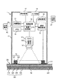
図1は、汚れ検査装置1の構成例を示す模式図である。本実施形態に係る汚れ検査装置1は、太陽光発電モジュール300の受光面301に載置され、受光面301の汚れ度合いを検査する。
<1. First Embodiment>
FIG. 1 is a schematic view showing a configuration example of the
太陽光発電モジュール300は、受光面301に入射する光を電気エネルギーに変換する発電装置である。太陽光発電モジュール300は、透光性を有する基板310と、封止樹脂層320と、太陽電池セル330と、バックフィルム340と、を備える。図1において、受光面301は、基板310の上面である。基板310の下面には、封止樹脂層320が設けられる。封止樹脂層320の下面には、バックフィルム340が設けられる。封止樹脂層320は、基板310とバックフィルム340との間に充填される透明な充填材である。太陽電池セル330は、基板310とバックフィルム340との間に設けられ、封止樹脂層320により封止される。太陽電池セル330には、本実施形態では多結晶シリコンが用いられる。但し、この例示に限定されず、GaAs系、Cu−In−Se系(CIS)系、Cu−In−Ga−Se系(CIGS)系、CdTe系などの材料を用いた化合物半導体太陽電池セル、色素増感型太陽電池セルなどが用いられてもよい。また、太陽光発電モジュール300は、図示を省略した端子ボックス及びケーブルをさらに備える。端子ボックスは、太陽電池セル330の出力を取り出し、ケーブルを通じて太陽光発電モジュール300の外部に出力する。
The photovoltaic
<1−1.汚れ検査装置>
図1に示すように、汚れ検査装置1は、ハウジング11と、照明装置12と、照明駆動装置13と、カメラ14と、メモリ15と、制御装置16と、表示装置17と、入力装置18と、通信装置19と、外部電源端子20と、内蔵電源21と、を備える。
<1-1. Dirt inspection device>
As shown in FIG. 1, the
ハウジング11は、有蓋筒状の円筒形状である。ハウジング11は、照明駆動装置13、カメラ14、メモリ15、制御装置16、通信装置19、及び内蔵電源21を内部に収容する。ハウジング11の蓋部分には、表示装置17及び入力装置18が設けられる。ハウジング11の筒部分には、外部電源端子20が設けられる。また、ハウジング11は、受光面301側の端部に開口111を有する。該開口111の内縁には、照明装置12が設けられる。
The
汚れ検査装置1が受光面301に載置される際、ハウジング11は、太陽光発電モジュール300の受光面301の一部領域Apを覆う。これにより、汚れ検査装置1は、外光に対して該一部領域Apを遮光した状態で測定を実施できるので、測定結果のノイズを抑制できる。また、ハウジング11は、本実施形態では樹脂製である。そのため、載置の際、ハウジング11が受光面301に当たっても、受光面301を傷つけ難くなっている。
When the
照明装置12は、受光面301の一部領域Apに光を照射する。照明装置12は、リング状の基体121と、LEDアレイ122を有する。LEDアレイ122は、基体121の径方向内端部に設けられ、周方向に並ぶ複数の白色LED(符号省略)を有する。各々の白色LEDは、所定の放射角度を有して径方向内方に白色光を出射し、少なくとも一部の白色光をハウジング11で覆われた受光面301の一部領域Apに照射する。該一部領域Apは、後述するように、汚れ検査装置1が受光面301の汚れ度合いを測定するための領域であり、本実施形態では直径がφ50[mm]〜φ200[mm]の領域である。
The
照明駆動装置13は、制御装置16から出力される制御信号に基づいて照明装置12を駆動し、特にLEDアレイ122の発光を制御する。
The
カメラ14は、受光面301の一部領域Apを撮像する撮像装置である。カメラ14が撮像する画像の画素数は、本実施形態では6万〜10万程度である。カメラ14は、レンズ141と、撮像素子142と、を有する。受光面301において上述の一部領域Apから入射する光は、レンズ141を通じて撮像素子142に入射する。撮像素子142には、CCD(charge coupled device)イメージセンサ、CMOS(complementary metal-oxide-semiconductor)イメージセンサなどが用いられる。
The camera 14 is an imaging device that captures a partial region Ap of the
メモリ15は、電力供給が停止しても記憶を維持する非一過性の記憶媒体である。メモリ15は、たとえば、汚れ検査装置1の各構成要素で用いられるプログラム及び制御情報、データなどを記憶する。また、メモリ15は、たとえば、カメラ14が撮像した画像データなども記憶する。
The
制御装置16は、メモリ15に記憶されたプログラム及び制御情報、データなどを用いて汚れ検査装置1の各構成要素を制御する。制御装置16は、後述する基準画像及び測定画像に基づいて受光面301の一部領域Apの汚れ度合いを数値化する。なお、汚れ度合いを測定する汚れ検査方法、及び、汚れ度合いの数値化の手法は、後に説明する。
The
制御装置16は、カメラ14により撮像された画像を処理する画像処理部161を有する。画像処理部161は、たとえば、カメラ14により撮像された測定画像の各々の画素の色座標と、後述する基準色座標とに基づいて、受光面301の汚れ度合いを算出する。これにより、太陽光発電モジュール300の受光面301の汚れ度合いを測定して精度良く数値化することができる。なお、測定画像は、汚れ検査装置1で汚れ度合いを測定する受光面301(の一部の領域)をカメラ14で撮像した画像である。基準色座標は、汚れ度合いを測定する際の基準となる色座標であり、本実施形態では汚れ検査装置1を用いて清浄な受光面301(の一部の領域)を撮像した基準画像に基づいて決定される。測定画像及び基準画像は、受光面301の撮像領域がハウジング11により覆われ且つ照明装置12から光が照射された状態で撮像されている。本実施形態では、基準画像及び測定画像の受光面301の撮像領域は、同じであってもよいし、異なっていてもよい。
The
表示装置17は、ハウジング11の上面に設けられたディスプレイ(図示省略)に汚れ度合いの測定値などを表示する。
The
入力装置18は、ユーザの操作入力を受け付ける。入力装置18は、汚れ検査装置1の起動/停止を操作するための電源ON/OFFボタン(図示省略)、後述するティーチングの実施を入力するためのティーチング開始ボタン(図示省略)、及び、汚れ検査装置1の測定開始を入力するための測定開始ボタン(図示省略)などを含む。これらのボタンは、ハウジング11の上面に設けられる。
The
なお、表示装置17及び入力装置18は、本実施形態では別々に設けられているが、この例示に限定されず、タッチパネルなどの一体の装置であってもよい。
Although the
通信装置19は、外部端末OTと無線又は有線で通信可能である。本実施形態では、Bluetooth(登録商標)により双方向の無線通信が可能である。外部端末OTは、たとえば、パーソナルコンピュータ、スマートフォンなどの携帯機器である。通信装置19は、たとえば、汚れ検査装置1の測定データ(汚れ度合いの数値など)を外部端末OTに送信できる。また、外部端末OTは、通信装置19との通信により、汚れ検査装置1を操作することもできる。
The
外部電源端子20は、外部電源ACと電気的に接続可能であり、外部電源ACから出力される電力を汚れ検査装置1の各構成要素に電力を供給できる。
The external
内蔵電源21は、汚れ検査装置1に内蔵されるバッテリーであり、放電して汚れ検査装置1の各構成要素に電力を供給できる。また、内蔵電源21は、外部電源端子20を介して外部電源ACから供給される電力により充電できる。
The built-in
<1−2.汚れ検査方法>
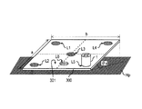
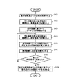
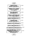
次に、汚れ検査装置1を用いた太陽光発電モジュール300の受光面301の汚れ検査方法を説明する。図2は、汚れ検査装置1を用いた汚れ検査方法の一例を示す模式図である。図3は、汚れ検査装置1を用いた汚れ検査方法の一例を説明するためのフローチャートである。なお、図2は、汚れ度合いを測定する際の太陽光発電モジュール300と汚れ検査装置1との位置関係を示す。また、図2の破線は、太陽光発電モジュール300の受光面301の縦幅aの方向における中央と横幅bの方向における中央とを表している。
<1-2. Dirt inspection method>
Next, a dirt inspection method for the
図2において、太陽光発電モジュール300は、屋外に設置され、水平な地面Hpに対して鉛直上方に傾斜角θv傾けて設置されている。太陽光発電モジュール300の縦幅はたとえばa=1.0[m]であり、横幅はたとえばb=1.7[m]である。傾斜角θvは、たとえば0°〜30°である。
In FIG. 2, the photovoltaic
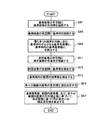
汚れ検査装置1を用いた汚れ検査方法では、図3に示すように、汚れ検査装置1にティーチングを行った後、受光面301の汚れ度合いを実測する。この汚れ検査方法により、太陽光発電モジュール300の受光面301の汚れ度合いを測定して精度良く数値化することができる。なお、ティーチングは、汚れ検査装置1に汚れ度合いの基準を設定する工程である。また、本実施形態では、受光面301の汚れ度合いを0〜100に数値化して示す。汚れ度合いの測定値は、清浄な受光面301では100であり、受光面301が汚れているほど小さくなる。目視で汚れが確認できる場合、測定値はたとえば23〜24程度となる。
In the stain inspection method using the
まず、受光面301上の基準領域L0及びその近傍が純粋又は精製水で洗浄されて清浄にされる(S101)。そして、基準領域L0上に汚れ検査装置1が載置され、ティーチング開始ボタンが押されることにより清浄な基準領域L0のRGBカラーの基準画像が撮像される(S103)。画像処理部161は、基準画像に基づいてティーチングを行う(S105)。なお、ティーチングの具体的な内容は後に説明する。
First, the reference region L0 on the
次に、ティーチングした汚れ検査装置1を用いて受光面301の汚れ度合いを実測する。この工程では、まず、受光面301上の測定領域L1上に汚れ検査装置1が載置されて、測定開始ボタンが押されることにより測定領域L1のRGBカラーの測定画像が撮像される(S111)。なお、測定領域L1での撮像は、1回でもよいし、複数回であってもよい。画像処理部161は、測定領域L1での撮影画像に基づいて測定領域L1における汚れ度合いを数値化してその測定値を算出する(S113)。表示装置17は、算出された測定値をディスプレイに表示する(S115)。ユーザは、ディスプレイを見て、測定領域L1での測定値を読み取ることができる。また、汚れ検査装置1は、外部端末OTに測定値を送信することもできる。
Next, the degree of dirt on the
測定領域L2〜L5でも、ステップS111〜S115と同じ処理が実施される(ステップS117でNO)。なお、測定領域の数は、本実施形態では5箇所であるが、この例示に限定されず、1箇所であってもよいし、5以外の複数箇所であってもよい。 In the measurement areas L2 to L5, the same processing as in steps S111 to S115 is performed (NO in step S117). Although the number of measurement regions is five in the present embodiment, the number of measurement regions is not limited to this example, and may be one or a plurality of measurement regions other than five.
全ての測定領域での測定が終了すると(ステップS117でYES)、各測定領域L1〜L5での測定値に基づいて、太陽光発電モジュール300の受光面301の汚れ度合いが算出される(S119)。たとえば、全ての測定領域L1〜L5での測定値の平均値が算出される。この際、たとえば、予め汚れ検査装置1に測定箇所数を入力しておくことにより、制御装置16にて全ての測定値の平均値が算出されて表示装置17に表示されてもよい。或いは、外部端末にて全ての測定値の平均値が算出されて、外部端末のディスプレイ(図示省略)に表示されてもよい。
When the measurement in all the measurement areas is completed (YES in step S117), the degree of contamination of the
なお、図2の汚れ検査方法では、ティーチングは、汚れ度合いを実測する検査対象の太陽光発電モジュール300を使って実施している。但し、この例示に限定されず、ティーチングは、検査対象とは異なる太陽光発電モジュールを使って実施されてもよい。この場合、ティーチングが実施される太陽光発電モジュールは、好ましくは、汚れ度合いを実測する検査対象の太陽光発電モジュール300と同じ又は類似する構成とされる。さらに、ティーチングは、汚れ度合いの実測前に、検査対象の太陽光発電モジュール300が設置場所とは異なる場所で予め実施されていてもよい。或いは、ティーチングは、実測の度に実施されなくてもよく、以前の実測で使用したティーチングの設定がそのまま使用されてもよい。
In the stain inspection method of FIG. 2, teaching is performed using the photovoltaic
また、図2及び図3では、小規模の太陽光発電所での検査例を説明した。一方、たとえば発電電力が1[MW]以上の大規模の太陽光発電所では、太陽光発電モジュールが複数個所に設置され、各々の太陽光発電モジュールのサイズも大きいため、各太陽光発電モジュールの受光面の汚れ度合いは不均一になり易い。このような場合には、たとえば、周囲の環境に影響されて比較的に汚れ易い場所を特定し、特定した各場所に設置された太陽光発電モジュールで測定を行い、それぞれの測定値の平均値をその太陽光発電所の汚れ度合いとすればよい。 Further, in FIGS. 2 and 3, an inspection example in a small-scale solar power plant was described. On the other hand, for example, in a large-scale photovoltaic power generation plant having a generated power of 1 [MW] or more, the photovoltaic power generation modules are installed in a plurality of locations and the size of each photovoltaic power generation module is large. The degree of dirt on the light receiving surface tends to be uneven. In such a case, for example, identify a place that is relatively easily soiled due to the influence of the surrounding environment, perform measurement with the photovoltaic power generation module installed at each specified place, and average the measured values. Should be the degree of dirtiness of the photovoltaic power plant.
<1−3.汚れ度合いの数値化>
次に、第1実施形態における汚れ度合いの数値化の手法の実施例とその変形例とを説明する。
<1-3. Quantification of degree of dirt>
Next, an example of the method for quantifying the degree of dirt in the first embodiment and a modified example thereof will be described.
<1−3−1.実施例>
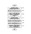
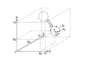
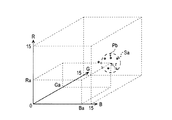
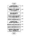
図4は、第1実施形態の実施例における汚れ度合いの数値化の手法を説明するためのフローチャートである。図5Aは、実施例における基準画像の色空間の一例である。図5Bは、測定画像の色空間の一例である。なお、図5Aにおいて、黒丸印は基準画像の画素Paである。図5Bにおいて、丸印は測定画像の画素Pbである。また、図5A及び図5Bでは、図を見易くするため、図示する画素Pa、Pbの数を実際よりも大幅に少なくしている。
<1-3-1. Example>
FIG. 4 is a flowchart for explaining a method for quantifying the degree of contamination in the embodiment of the first embodiment. FIG. 5A is an example of the color space of the reference image in the embodiment. FIG. 5B is an example of the color space of the measured image. In FIG. 5A, the black circles are the pixels Pa of the reference image. In FIG. 5B, the circles are pixels Pb of the measurement image. Further, in FIGS. 5A and 5B, the number of pixels Pa and Pb shown is significantly smaller than the actual number in order to make the figure easier to see.
色空間は、色成分R(Red)の大きさ、色成分G(Green)の大きさ、及び、色成分B(Blue)の大きさで色相を表す3次元の仮想空間である。以下では、色成分R(Red)の大きさをR成分値と呼ぶ。また、色成分G(Green)の大きさをG成分値とよび、色成分B(Blue)の大きさをB成分値と呼ぶ。色空間における色相の色座標(R、G、B)は、R成分値、G成分値、及びB成分値で表される。本実施形態では、演算負荷を考慮して、各色成分値を16階調(つまり0〜15)で表している。但し、各色成分値の階調数は、この例示に限定されない。たとえば、階調数は、256であってもよい。 The color space is a three-dimensional virtual space in which the hue is represented by the size of the color component R (Red), the size of the color component G (Green), and the size of the color component B (Blue). Hereinafter, the magnitude of the color component R (Red) is referred to as an R component value. Further, the size of the color component G (Green) is called the G component value, and the size of the color component B (Blue) is called the B component value. The hue coordinates (R, G, B) in the color space are represented by the R component value, the G component value, and the B component value. In the present embodiment, each color component value is represented by 16 gradations (that is, 0 to 15) in consideration of the calculation load. However, the number of gradations of each color component value is not limited to this example. For example, the number of gradations may be 256.
まず、基準領域L0(図2参照)でのティーチングの際、図5Aに示すように、画像処理部161は、基準画像の各画素PaのR成分値、G成分値、及びB成分値を算出し、各色成分値を色座標(R、G、B)とする画素Paを色空間にそれぞれ描画する(S301)。なお、基準画像の画素Paの色座標は、本発明の「第2色座標」の一例である。画像処理部161は、所定の半径rを有する球状の領域を基準画像の色空間内に描画する(S303)。以下では、この球状の領域を基準球Saと呼ぶ。基準球Saは、本発明の「基準色範囲」の一例である。基準球Saの半径rは、本実施形態では4階調にしている。但し、この例示に限定されず、半径rは4以外であってもよい。
First, during teaching in the reference region L0 (see FIG. 2), as shown in FIG. 5A, the
画像処理部161は、基準画像の色空間において基準球Saを各軸方向に動かす。画像処理部161は、基準球Sa内に色座標(R、G、B)がある基準画像の画素Paの数が最大となるように基準球Saの位置を決定するとともに、該基準球Sa内に色座標(R、G、B)がある基準画像の画素Paを検出する。以下では、基準球Sa内にある画素Paを基準画素Pamと呼び、基準画素Pamの数を基準画素数mと呼ぶ。基準画素数mは、正の整数であり、1より大きく且つ基準画像を構成する画素の総数以下である。より具体的には、画像処理部161は、最も多くの基準画素Pamが基準球Saの内部に含まれる際の該基準球Saの中心となる基準色座標(Ra、Ga、Ba)を検出する。つまり、基準色座標(Ra、Ga、Ba)は、基準画像の色空間において、該基準色座標(Ra、Ga、Ba)を中心とする所定の大きさの基準球Sa内に色座標(R、G、B)がある基準画素数mが最大となるようにされる。さらに、画像処理部161は、基準画素数mも検出する(S305)。基準色座標(Ra、Ga、Ba)及び基準画素数mは、メモリ15に記憶される。
The
次に、たとえば測定領域L1〜L5(図2参照)にて受光面301の汚れ度合いを実測する際、図5Bに示すように、画像処理部161は、撮像された測定画像の各画素PbのR成分値、G成分値、及びB成分値を算出し、各色成分値を色座標(R、G、B)とする画素Pbを測定画像の色空間にそれぞれ描画する(S311)。なお、測定画像の画素の色座標(R、G、B)は、本発明の「第1色座標」の一例である。画像処理部161は、さらに、基準色座標(Ra、Ga、Ba)に中心が位置する半径rの基準球Saを測定画像の色空間内に描画する(S313)。画像処理部161は、基準球Sa内に色座標(R、G、B)がある測定画像の画素Pbを検出し、基準球Sa内にある画素Pbの数を検出する(S315)。本実施形態では、基準球Sa内にある各々の画素Pbのカウント値は、1個の画素Pbに対して1である。以下では、基準球Sa内にある画素Pbを範囲内画素Pbnと呼び、範囲内画素Pbnの数を範囲内画素数nと呼ぶ。範囲内画素数nは、正の整数であり、1より大きく且つ測定画像を構成する画素の総数以下である。
Next, for example, when actually measuring the degree of contamination of the
画像処理部161は、S315での画素の検出結果に基づいて受光面301の汚れ度合いを算出する。たとえば、画像処理部161は、基準画素数m及び範囲内画素数nに基づいて汚れ度合いを算出し、基準画素数mに対する範囲内画素数nの比率により汚れ度合いの測定値を算出する(S317)。本実施形態では、画像処理部161は、範囲内画素数nを基準画素数mで割った値の百分率を算出し、測定画像に基づく汚れ度合いの測定値とする。たとえば、図5Bの場合、測定値は80となる。なお、測定値を0〜100の範囲内で数値化するため、範囲内画素数nが基準画素数mよりも大きい場合(つまり百分率が100を越える場合)、測定画像に対する測定値は100とされる。
The
画像処理部161は、カメラ14で測定画像を撮像する毎に、上述の処理を実施する。なお、測定開始ボタンを1回押したときに複数の測定画像が撮像される際には、該測定画像に対する測定値の平均値が、1回の測定における代表の測定値とされてもよい。
The
以上に説明した、汚れ検査方法によれば、基礎画像と測定画像とが受光面301の異なる箇所を撮像した画像であっても、太陽光発電モジュール300の受光面301の汚れ度合いを測定して精度良く数値化することができる。
According to the stain inspection method described above, even if the basic image and the measurement image are images of different parts of the
<1−3−2.変形例>
上述の実施例ではティーチングの際、画像処理部161はたとえば、基準画像の色空間内において基準球Saを各軸方向に1階調ずつ移動させて、その都度、基準球Sa内にある基準画素数mを検出する。但し、この手法では、たとえば各色成分値の階調数の3乗(本実施形態では163)回の検出処理を行うことになるため、演算負荷が高くなり易い。さらに、各色成分値の階調数が多いほど、演算負荷は大幅に増大する。このような演算負荷を軽減するため、変形例では、以下に説明する手法で汚れ度合いの測定値を算出する。
<1-3-2. Modification example>
In the above-described embodiment, during teaching, the
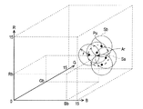
図6は、第1実施形態の変形例における汚れ度合いの数値化の手法を説明するためのフローチャートである。図7は、変形例における基準画像の色空間の一例である。なお、図7において、黒丸印は基準画像の画素Paである。また、図7では、図を見易くするため、図示する画素Pa及び後述する測定球Sbの数を実際よりも大幅に少なくしている。 FIG. 6 is a flowchart for explaining a method for quantifying the degree of contamination in the modified example of the first embodiment. FIG. 7 is an example of the color space of the reference image in the modified example. In FIG. 7, the black circles are the pixels Pa of the reference image. Further, in FIG. 7, in order to make the figure easier to see, the number of the illustrated pixel Pa and the measurement sphere Sb described later is significantly smaller than the actual number.
変形例では、基準領域L0(図2参照)でのティーチングの際、図7に示すように、画像処理部161は、基準画像の各画素PaのR成分値、G成分値、及びB成分値を算出し、各色成分値を色座標(R、G、B)とする画素Paを色空間にそれぞれ描画する(S501)。
In the modified example, when teaching in the reference region L0 (see FIG. 2), as shown in FIG. 7, the
そして、基準画像の基準球Sa内に色座標(R、G、B)がある基準画素数mが最大となるように該基準球Saを決定するため、ステップS503〜S505を実施する。まず、画像処理部161は、基準画像の各々の画素Paの色座標(R、G、B)を中心とする球状の領域(以下、測定球Sbと呼ぶ。)を基準画像の色空間にそれぞれ描画する(S503)。なお、測定球Sbは、本発明の「色範囲」の一例である。また、測定球Sbの半径は、上述する実施例の基準球Saの半径rと同じである。画像処理部161は、色空間において、基準画像の各々の画素の色座標(R、G、B)を中心とする所定の大きさの測定球Sbの重なりが最も多い最多重領域Ar(図7の斜線で示す領域)を算出し、最多重領域Arに基づいて基準色座標(Rb、Bb、Gb)を決定する(S505)。なお、基準色座標(Ra、Ga、Ba)は、たとえば、最多重領域Arを含む基準球Saに対応する画素Paの色座標(R、G、B)を平均することで算出できる。また、基準色座標(Ra、Ga、Ba)を算出する際、最多重領域Arが複数ある場合、たとえば、そのうちのいずれかの最多重領域Arの基準色座標を基準球Saの中心として採用してもよい。或いは、複数の最多重領域Arの各基準色座標を平均した色座標を基準球Saの中心として採用してもよい。
Then, steps S503 to S505 are performed in order to determine the reference sphere Sa so that the number of reference pixels m having color coordinates (R, G, B) in the reference sphere Sa of the reference image is maximized. First, the
次に、画像処理部161は、基準色座標(Rb、Bb、Gb)を中心とする半径rの基準球Saを基準画像の色空間に描画する(S507)。そして、画像処理部161は、基準画像から基準球Sa内にある基準画素Pamをそれぞれ検出し、基準球Saの内部に含まれる基準画素数mを検出する(S509)。
Next, the
以降のステップS511〜S517はそれぞれ、実施例(図4)のステップS311〜S317と同じであるため、その説明を省略する。 Subsequent steps S511 to S517 are the same as steps S311 to S317 of the embodiment (FIG. 4), respectively, and thus the description thereof will be omitted.
変形例の手法では、ティーチングの際に基準色座標(Ra、Ga、Ba)を決定する際、基準画像の色空間において基準球Saを各軸方向に動かす必要が無い。そのため、実施例と比べて、演算負荷を大幅に軽減することができる。 In the modified example method, when determining the reference color coordinates (Ra, Ga, Ba) at the time of teaching, it is not necessary to move the reference sphere Sa in each axial direction in the color space of the reference image. Therefore, the calculation load can be significantly reduced as compared with the embodiment.
<1−4.汚れ検査方法を応用した太陽光発電モジュールの管理方法>
次に、汚れ検査装置1を用いた汚れ検査方法を応用した太陽光発電モジュール300の管理方法の一例を説明する。通常、屋外に設置された太陽光発電モジュール300は、風雨、温度、汚染ガス、飛散物、積雪、生物体汚染などの厳しい環境下に置かれる。そのため、設置から数年経過すると、”洗浄時期”になった、”そろそろ洗浄時期に近づいた”などの意見が、太陽光発電モジュール300のO&M(operation and maintenance)業者、又は太陽光発電所の管理者から出される。従来では、太陽光発電モジュール300の受光面301の汚れ度合いを測定する方法が確立されていなかったため、実務経験又は慣例などにより受光面301の洗浄時期が決められていた。そして、手動の洗浄、高圧水洗浄、受光面301に載置される自走式の自動洗浄装置による洗浄などが行われ、洗浄前後の発電電力の差に基づいて発電電力の回復量が評価されるのみであった。つまり、受光面301の汚れ度合いと洗浄による発電電力の回復量とを数値化しておらず、両者の相関関係を理論的に管理されていなかった。以下に説明する太陽光発電モジュール300の管理方法は、これらを新規に改善するものである。
<1-4. Management method of photovoltaic power generation module applying dirt inspection method>
Next, an example of a management method of the photovoltaic
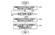
図8は、太陽光発電モジュール300の管理方法の一例を説明するためのフローチャートである。
FIG. 8 is a flowchart for explaining an example of a management method of the photovoltaic
まず、太陽光発電モジュール300の発電電力Wbと受光面301の汚れ度合いSbとを測定し、測定日時とともに記録する(S701)。受光面301の汚れ度合いSbは、たとえば、上述の汚れ検査装置1(図1参照)を用いて、上述の汚れ検査方法(図3参照)により測定する。
First, the generated power Wb of the photovoltaic
さらに、S701が実施された時点から所定の経過期間Tが経過した後(ステップS703でYES)、太陽光発電モジュール300の発電電力Waと受光面301の汚れ度合いSaとを測定し、測定日時とともに記録する(S705)。なお、経過期間Tは、日単位、週単位、月単位、又は年単位であってもよい。また、ステップS705は、好ましくはステップS701と同じ日射条件(日射強度、天候)の時期に実施される。
Further, after a predetermined elapsed period T has elapsed from the time when S701 is executed (YES in step S703), the generated power Wa of the photovoltaic
そして、ステップS701で測定した受光面301の汚れ度合いSb及び太陽光発電モジュール300の発電電力Wbと、ステップ705で測定した受光面301の汚れ度合いSa及び太陽光発電モジュール300の発電電力Waと、ステップS701からS705までの経過期間Tと、に基づいて、太陽光発電モジュール300の受光面301の洗浄時期が決定される(S707)。
Then, the degree of contamination Sb of the
ステップS707では、たとえば、まず、清浄面での汚れ度合いと洗浄前での汚れ度合いSbとの差(Sa−Sb)を経過期間Tで割り算することにより、受光面301の汚れ速度ΔS={(Sa−Sb)/T}を算出する。
In step S707, for example, first, the difference (Sa-Sb) between the degree of dirt on the clean surface and the degree of dirt Sb before cleaning is divided by the elapsed period T, so that the dirt rate ΔS = {() of the
また、汚れ度合いの差(Sa−Sb)を今回の洗浄前後での発電電力の差(Wa−Wb)で割り算することにより、汚れ度合いに対する発電電力の変化率ΔW={(Sa−Sb)/(Wa−Wb)}を算出する。 Further, by dividing the difference in the degree of dirt (Sa-Sb) by the difference in the generated power before and after this cleaning (Wa-Wb), the rate of change of the generated power with respect to the degree of dirt ΔW = {(Sa-Sb) / (Wa-Wb)} is calculated.
また、受光面301を洗浄する際の発電電力の閾値Wsを設定し、上述の汚れ速度ΔS及び変化率ΔWを用いて、発電電力が閾値Wsになる時期を受光面301の洗浄時期として算出する。閾値Wsは、たとえば、太陽光発電モジュール300に要求される発電電力の下限値に基づいて設定できる。或いは、閾値Wsは、太陽光発電モジュール300の洗浄費用に対する該太陽光発電モジュール300の発電電力の売電価格の費用対効果を考慮して設定できる。たとえば、該太陽光発電モジュール300の発電電力を経過期間Tにおいて売電したときに得られる利益について、今回の洗浄をした場合と今回の洗浄をしなかった場合との比較を行い、両者の差額が洗浄費用以上になるように、閾値Wsを決定できる。また、上述の差額が洗浄費用を十分に上回って所定の利益が得られるように、閾値Wsを決定することもできる。本実施形態では、上述の費用対効果を考慮して、閾値Wsは、太陽光発電モジュール300を設置開始時期での発電電力Woの90[%]程度の値に設定している。
Further, the threshold value Ws of the generated power when cleaning the
なお、ステップS701又はS705の時点で、発電電力Wb、Waが、閾値Ws未満であった場合には、該時点又はこれに近い日時を太陽光発電モジュール300を洗浄する日に決定してもよい。
If the generated powers Wb and Wa are less than the threshold value Ws at the time of step S701 or S705, the time or a date close to that time may be determined as the day when the photovoltaic
また、図8の管理方法では、ステップS701〜S705を1回行っている。但し、図8の例示に限定されず、ステップS701〜S705は、ステップS707を実施する前に複数回行ってもよい。この場合、ステップS707では、各経過期間Tと、各経過期間Tの開始時及び終了時における受光面301の汚れ度合いSb、Sa及び太陽光発電モジュール300の発電電力Wb、Waとに基づいて、太陽光発電モジュール300の受光面301の洗浄時期を決定する。こうすれば、受光面301の洗浄時期をさらに精度良く算出できる。
Further, in the management method of FIG. 8, steps S701 to S705 are performed once. However, the present invention is not limited to the example of FIG. 8, and steps S701 to S705 may be performed a plurality of times before the step S707 is performed. In this case, in step S707, based on each elapsed period T and the degree of contamination Sb and Sa of the
さらに、ステップS701〜S705を複数回行う際、好ましくは、各回での経過期間Tのうちの一部は、他の一部と異なる時間長とされる。さらに好ましくは、各回での経過期間Tは全て、それぞれ異なる時間長とされる。こうすれば、受光面301の汚れ速度ΔS及び汚れ度合いに対する発電電力の変化率ΔWのより正確な変化を得ることが確認できる。従って、受光面301の汚れ速度ΔS及び/又は汚れ度合いに対する発電電力の変化率ΔWの変化が非線形であっても、受光面301の洗浄時期をより正確に決定できる。
Further, when steps S701 to S705 are performed a plurality of times, it is preferable that a part of the elapsed period T in each time has a different time length from the other part. More preferably, the elapsed period T at each time is set to a different time length. By doing so, it can be confirmed that a more accurate change in the dirt rate ΔS of the
また、上述の管理方法において、ステップS701及びS705は、好ましくは、一日のうちの早朝及び夕方のうちの少なくとも一方で実施される。 Also, in the management method described above, steps S701 and S705 are preferably performed at least one of the early morning and the evening of the day.
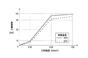
たとえば、太陽光に含まれる各波長の光の強度比は経時変化しないが、太陽光発電モジュール300に入射する太陽光の日射強度は、主に、太陽の高度及び日射角度で変化する。1日の時間帯では、通常、12:00〜14:00が最大となる。1日における日射強度に対する太陽光発電モジュール300の発電電力の関係はたとえば図9のようになる。日射強度は、図9では、日の出を含む夜明け時及び日の入りを含む夕暮れ時では0.20[kW/m2]未満であり、正午を含む真昼では0.60[kW/m2]よりも大きく、これらの間となる早朝及び夕方では、0.20[kW/m2]以上且つ0.60[kW/m2]以下である。このように、日射強度に対する発電電力の変化率は、早朝及び夕方で最も大きくなる。なお、この傾向は、太陽光発電モジュール300の周囲温度が変化しても変わらない。
For example, the intensity ratio of light of each wavelength contained in sunlight does not change with time, but the solar radiation intensity of sunlight incident on the photovoltaic
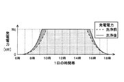
また、太陽光発電モジュール300の発電電力は、通常、発電電力のピーク時に近い時間帯で複数の太陽光発電所から売電される逆潮流電力が急減に増加しないようにするため、PCS(power control system)により上限閾値Wcを越えないように抑制制御される。そのため、図10に示すように、たとえば10時前〜15時過ぎを含む真昼に、上述の管理方法、特にステップS701及びS705を実施しても、太陽光発電モジュール300の発電電力の差を評価できないことがある。また、図10のたとえば6時以前の夜明け時及び17時以降の夕暮れ時では、洗浄前後での太陽光発電モジュール300の発電電力の増加量が非常に小さい。そのため、太陽光発電モジュール300の発電電力の差が解りづらい。一方、たとえば6時〜10前の早朝及びたとえば15時過ぎ〜17時の夕方では、PCSの出力抑制制御が実施されず、太陽光発電モジュール300の発電電力の増加量も比較的大きい。
Further, the generated power of the photovoltaic
従って、上述の管理方法、特にステップS701及びS705を早朝及び/又は夕方に行うことにより、受光面301の汚れ度合いの進行によって発電電力が低下する傾向をより正確に検出できる。よって、太陽光発電モジュール300の受光面301の洗浄時期をさらに正確に算出できる。
Therefore, by performing the above-mentioned management methods, particularly steps S701 and S705 in the early morning and / or in the evening, it is possible to more accurately detect the tendency that the generated power decreases as the degree of contamination of the
また、上述の管理方法では、汚れ検査装置1を用いて受光面301の汚れ度合いを検出した。但し、この例示に限定されず、受光面301の汚れ度合いは、汚れ検査装置1以外の装置を用いて検出されてもよい。たとえば、受光面301が汚れていると光の乱反射が起き易いことを利用し、測定対象物の表面の光沢度を測定する光沢計、又は、測定対象物の表面からの反射光の輝度を測定する輝度計などを用いてもよい。受光面301上の複数点の光沢度又は輝度をピンポイントで測定し、汚れた受光面301での各測定値と、清浄な受光面301での基準測定値とを比較することにより、汚れ度合いを評価することもできる。但し、光沢計及び輝度計の測定領域のサイズは、本実施形態の汚れ検査装置1の測定領域と比べて非常に狭い。そのため、本実施携帯の汚れ検査装置1よりも精度が低くなり易い。従って、受光面301の汚れ度合いを十分に正確に評価するためには、汚れ検査装置1を用いる場合と比べてより多くの測定点で測定を行う必要がある。
Further, in the above-mentioned management method, the degree of dirt on the
<2.第2実施形態>
上述の第1実施形態では、受光面301を覆う汚れの色相は考慮していない。しかしながら、実際には、汚れの色相は、太陽光発電モジュール300の発電電力の変動に大きく影響する。たとえば、色相を考慮しない汚れ度合いが同程度であっても、汚れの色が黒に近いほど、発電電力の低下はより大きくなる。一方、汚れの色が白に近いほど、発電電力の低下は軽減される。そこで、第2実施形態では、第1実施形態(図4参照)又はその変形例(図6参照)で算出した測定値を汚れの色相を考慮して補正した補正測定値を算出する。これ以外は、第1実施形態と同様である。以下では、第1実施形態と異なる構成を説明する。また、第1実施形態と同様の構成要素には同じ符号を付し、さらに、第1実施形態と同様の構成の説明を省略することがある。
<2. Second Embodiment>
In the first embodiment described above, the hue of the stain covering the
<2−1.汚れ検査装置>
第2実施形態において、汚れ検査装置1の画像処理部161は、測定画像の各々の画素の色座標(R、G、B)と、基準色座標(Ra、Ga、Ba)と、測定画像の各々の画素の色座標(R、G、B)に対応する色成分別の補正値Nr、Ng、Nbとに基づいて、受光面301の汚れ度合いの補正測定値を算出する。色成分別の補正値Nr、Ng、Nbはそれぞれ、測定画像の各々の画素Pbの色座標(R、G、B)に対応して設定されている。色成分別の補正値Nr、Ng、Nbの設定情報は、たとえばメモリ15に記憶されている。
<2-1. Dirt inspection device>
In the second embodiment, the
具体的には、色成分別の補正値Nr、Ng、Nbはそれぞれ、測定画像の色空間において基準球Sa内にある画素(つまり範囲内画素Pbn)の色座標(R、G、B)に対応する色成分別の補正値Nrn、Ngn、Nbnを含む。画像処理部161は、各々の範囲内画素Pbnのカウント値を色成分別の補正値Nrn、Ngn、Nbnによって補正し、補正後のカウント値を用いて汚れ度合いの補正測定値を算出する。なお、以下では、各々の範囲内画素Pbnの補正後のカウント値を補正カウント値naと呼ぶ。
Specifically, the correction values Nr, Ng, and Nb for each color component are set to the color coordinates (R, G, B) of the pixels (that is, the within-range pixels Pbn) in the reference sphere Sa in the color space of the measured image, respectively. Includes correction values Nrn, Ngn, and Nbn for each corresponding color component. The
たとえば、範囲内画素PbnのR成分値に対応する補正値Nrnは、R成分値が最大の階調値(たとえば15)に近いほどより小さく設定され、R成分値が最大の階調値の場合に最小値(たとえば1より小さい値)に設定される。一方、該補正値Nrnは、R成分値が最小の階調値(たとえば0)に近いほどより大きく設定され、R成分値が最小の階調値の場合に最大値(たとえば1より大きい値)に設定される。 For example, the correction value Nrn corresponding to the R component value of the within-range pixel Pbn is set smaller as the R component value approaches the maximum gradation value (for example, 15), and when the R component value is the maximum gradation value. Is set to the minimum value (for example, a value smaller than 1). On the other hand, the correction value Nrn is set larger as the R component value is closer to the minimum gradation value (for example, 0), and is the maximum value (for example, a value larger than 1) when the R component value is the minimum gradation value. Is set to.
範囲内画素Pbnの他の色成分別の補正値Ngn、Nbnも同様である。たとえば、範囲内画素PbnのG成分値に対応する補正値Ngnは、G成分値が最大の階調値(たとえば15)に近いほどより小さく設定され、G成分値が最大の階調値の場合に最小値(たとえば1より小さい値)に設定される。一方、該補正値Ngnは、G成分値が最小の階調値(たとえば0)に近いほどより大きく設定され、G成分値が最小の階調値の場合に最大値(たとえば1より大きい値)に設定される。 The same applies to the correction values Ngn and Nbn for each of the other color components of the within-range pixels Pbn. For example, the correction value Ngn corresponding to the G component value of the within-range pixel Pbn is set smaller as the G component value approaches the maximum gradation value (for example, 15), and when the G component value is the maximum gradation value. Is set to the minimum value (for example, a value smaller than 1). On the other hand, the correction value Ngn is set larger as the G component value is closer to the minimum gradation value (for example, 0), and is the maximum value (for example, a value larger than 1) when the G component value is the minimum gradation value. Is set to.
また、範囲内画素PbnのB成分値に対応する補正値Nbnは、B成分値が最大の階調値(たとえば15)に近いほどより小さく設定され、B成分値が最大の階調値の場合に最小値(たとえば1より小さい値)に設定される。一方、該補正値Nbnは、B成分値が最小の階調値(たとえば0)に近いほどより大きく設定され、B成分値が最小の階調値の場合に最大値(たとえば1より大きい値)に設定される。 Further, the correction value Nbn corresponding to the B component value of the within-range pixel Pbn is set smaller as the B component value is closer to the maximum gradation value (for example, 15), and when the B component value is the maximum gradation value. Is set to the minimum value (for example, a value smaller than 1). On the other hand, the correction value Nbn is set larger as the B component value is closer to the minimum gradation value (for example, 0), and is the maximum value (for example, a value larger than 1) when the B component value is the minimum gradation value. Is set to.
これらの色成分別の補正値Nrn、Ngn、Nbnは、たとえば、太陽電池セル330の材料のバンドギャップ、受光面301に入射する光の色相に応じた光反射率などに基づいて設定できる。
The correction values Nrn, Ngn, and Nbn for each of these color components can be set based on, for example, the band gap of the material of the
<2−2.汚れ度合いの数値化>
次に、第2実施形態における汚れ度合いの数値化の手法の実施例とその変形例とを説明する。
<2-2. Quantification of degree of dirt>
Next, an example of the method for quantifying the degree of dirt in the second embodiment and a modified example thereof will be described.
<2−2−1.実施例>
図11は、第2実施形態の実施例における汚れ度合いの数値化の手法を説明するためのフローチャートである。なお、図11のステップS901〜S915は、第1実施形態の実施例(図4)のステップS301〜S315と同様である。
<2-2-1. Example>
FIG. 11 is a flowchart for explaining a method for quantifying the degree of contamination in the embodiment of the second embodiment. Note that steps S901 to S915 in FIG. 11 are the same as steps S301 to S315 in the embodiment (FIG. 4) of the first embodiment.
ステップS915では、基準球Saに含まれるn個の範囲内画素Pbnが検出される。画像処理部161は、メモリ15に記憶された設定情報を参照して、各々の範囲内画素Pbnの色成分別の補正値Nrn、Ngn、Nbnをそれぞれ決定する(S916)。そして、画像処理部161は、S905で検出した基準画素数m、S915で検出した範囲内画素数n、及び、各々の範囲内画素Pbnの色成分別の補正値Nrn、Ngn、Nbnに基づいて測定画像に基づく汚れ度合いの補正測定値を算出する(S917)。
In step S915, n in-range pixels Pbn included in the reference sphere Sa are detected. The
つまり、S917において、画像処理部161は、測定画像の各々の画素Pbの色座標(R、G、B)と、基準色座標(Ra、Ga、Ba)と、測定画像の各々の画素Pbの色座標(R、G、B)に対応する色成分別の補正値Nr、Ng、Nbとに基づいて、受光面301の汚れ度合いの補正測定値を算出する。言い換えると、画像処理部161は、測定画像の各々の画素Pbの色座標(R、G、B)と、基準色座標(Ra、Ga、Ba)とに基づく受光面301の汚れ度合いの測定値を、さらに測定画像の各々の画素Pbの色座標(R、G、B)に対応する色成分別の補正値Nr、Ng、Nbに基づいて補正した補正測定値を算出する。
That is, in S917, the
たとえば本実施形態では、まず、画像処理部161は、各々の範囲内画素Pbnの補正カウント値na=(Nrn×Ngn×Nbn)を算出する。補正カウント値naは、前述のごとく、第2実施形態において汚れの色相を考慮して、各々の範囲内画素Pbnのカウント値を補正した値である。なお、第1実施形態のように、汚れの色相を考慮しない場合、各々の範囲内画素Pbnのカウント値は1である。
For example, in the present embodiment, first, the
さらに、画像処理部161は、n個の範囲内画素Pbnにおける補正カウント値naの総和Σna={(Nr1×Ng1×Nb1)+(Nr2×Ng2×Nb2)+・・・+(Nrn×Ngn×Nbn)}を算出する。
Further, the
そして、画像処理部161は、補正カウント値naの総和Σnaの基準画素数mに対する比率{(Σna)/m}により汚れ度合いを算出する。第2実施形態では、画像処理部161は、百分率{100×(Σna)/m}を測定画像に基づく汚れ度合いの測定値とする。なお、百分率が100を越える場合、測定画像に対する汚れ度合いの測定値は100とされる。
Then, the
画像処理部161は、カメラ14で測定画像を撮像する毎に、図11の処理を実施する。なお、測定開始ボタンを1回押したときに複数の測定画像が撮像される際には、測定値の平均値が、1回の測定における代表の測定値とされてもよい。
The
上述のように第2実施形態では、画像処理部161は、測定画像の各々の画素Pbの色座標(R、G、B)と、基準色座標(Ra、Ga、Ba)とに基づく受光面301の汚れ度合いの測定値を、さらに測定画像の各々の画素Pbの色座標(R、G、B)に対応する色成分別の補正値Nr、Ng、Nbに基づいて補正する。言い換えると、画像処理部161は、測定画像の各々の画素Pbの色座標(R、G、B)と、基準色座標(Ra、Ga、Ba)と、測定画像の各々の画素Pbの色座標(R、G、B)に対応する色成分別の補正値Nr、Ng、Nbとに基づいて、受光面301の汚れ度合いの補正測定値を算出する。上述のように、色相を考慮しない汚れ度合いの測定値を色成分別の補正値Nrn、Ngn、Nbnを用いて補正することにより、太陽光発電モジュール300の発電電力の変動に対する受光面301を覆う汚れの色相の影響を考慮できる。従って、汚れ検査装置1を用いて太陽光発電モジュール300の発電電力が低下する傾向をより正確に検出できる。
As described above, in the second embodiment, the
<2−2−2.変形例>
なお、ティーチングの際の演算負荷を軽減するため、図4(つまり第1実施形態の変形例)と同様の手法が採用されてもよい。図12は、第2実施形態の変形例における汚れ度合いの数値化の手法を説明するためのフローチャートである。図12のステップS1101〜S1115は、第1実施形態の変形例(図6)のステップS501〜S515と同様である。さらに、図12のステップS1116〜S1117は、第2実施形態の実施例(図11)のステップS916〜S917と同様である。画像処理部161は、カメラ14で測定画像を撮像する毎に、図12の処理を実施する。なお、測定開始ボタンを1回押したときに複数の測定画像が撮像される際には、測定値の平均値が、1回の測定における代表の測定値とされてもよい。
<2-2-2. Modification example>
In addition, in order to reduce the calculation load at the time of teaching, the same method as in FIG. 4 (that is, a modified example of the first embodiment) may be adopted. FIG. 12 is a flowchart for explaining a method for quantifying the degree of contamination in the modified example of the second embodiment. Steps S1101 to S1115 of FIG. 12 are the same as steps S501 to S515 of the modified example (FIG. 6) of the first embodiment. Further, steps S1116 to S1117 of FIG. 12 are the same as steps S916 to S917 of the second embodiment (FIG. 11). The
<2−3.汚れ検査方法を応用した太陽光発電モジュールの管理方法>
第2実施形態では、汚れ検査装置1を用いた汚れ検査方法を応用した太陽光発電モジュール300の管理方法(図8参照)において、上述の補正測定値を用いる。たとえば、図8のステップS701及びS705において、受光面301の汚れ度合いSb、Saの補正測定値が、たとえば、上述の汚れ検査装置1(図1参照)を用いて、上述の汚れ検査方法(図11、図12参照)により測定される。つまり、測定画像の各々の画素Pbの色空間における色座標(R、G、B)と、色空間における基準色座標(Ra、Ga、Ba)とに基づく汚れ度合いの測定値Sb、Saを、色座標(R、G、B)に対応する色成分別の補正値Nr、Ng、Nbに基づいて補正した汚れ度合いの補正測定値が算出される。そして、上述の汚れ度合いの各々の補正測定値と、図8のステップS701及びS705にて測定した各々の発電電力Wb、Waと、経過期間Tとに基づいて、受光面301の洗浄時期が決定される。色相を考慮した汚れ度合いの補正測定値を用いることにより、太陽光発電モジュール300の発電電力が低下する傾向をさらに正確に検出できる。従って、受光面301の洗浄時期をさらに精度良く算出できる。
<2-3. Management method of photovoltaic power generation module applying dirt inspection method>
In the second embodiment, the above-mentioned corrected measurement value is used in the management method (see FIG. 8) of the photovoltaic
<3.備考>
以上、本発明の実施形態について説明した。なお、上述の実施形態は例示であり、その各構成要素及び各処理の組み合わせに色々な変形が可能であり、本発明の範囲にあることは当業者に理解されるところである。
<3. Remarks>
The embodiment of the present invention has been described above. It should be noted that the above-described embodiment is an example, and various modifications can be made to the combination of each component and each process, and it is understood by those skilled in the art that it is within the scope of the present invention.
たとえば、上述の実施形態において、制御装置16の機能的な構成要素のうちの少なくとも一部又は全部は、物理的な構成要素(たとえば電気回路、素子、装置など)で実現されていてもよい。
For example, in the above-described embodiment, at least a part or all of the functional components of the
100 管理システム
1 汚れ検査装置
11 ハウジング
111 開口
12 照明装置
121 基体
122 LEDアレイ
13 照明駆動装置
14 カメラ
141 レンズ
142 撮像素子
15 メモリ
16 制御装置
161 画像処理部
17 表示装置
18 入力装置
19 通信装置
20 外部電源端子
21 内蔵電源
300 太陽光発電モジュール
301 受光面
310 透光性基板
320 封止樹脂層
330 太陽電池セル
340 バックフィルム
OT 外部端末
AC 外部電源
L0 基準領域
L1〜L5 測定領域
Pa、Pb 画素
Pam 基準画素
Pbn 範囲内画素
Sa 基準球
Sb 測定球
Ar 最多重領域
100
そして、基準画像の基準球Sa内に色座標(R、G、B)がある基準画素数mが最大となるように該基準球Saを決定するため、ステップS503〜S505を実施する。まず、画像処理部161は、基準画像の各々の画素Paの色座標(R、G、B)を中心とする球状の領域(以下、測定球Sbと呼ぶ。)を基準画像の色空間にそれぞれ描画する(S503)。なお、測定球Sbは、本発明の「基準色範囲」の一例である。また、測定球Sbの半径は、上述する実施例の基準球Saの半径rと同じである。画像処理部161は、色空間において、基準画像の各々の画素の色座標(R、G、B)を中心とする所定の大きさの測定球Sbの重なりが最も多い最多重領域Ar(図7の斜線で示す領域)を算出し、最多重領域Arに基づいて基準色座標(Rb、Bb、Gb)を決定する(S505)。なお、基準色座標(Ra、Ga、Ba)は、たとえば、最多重領域Arを含む基準球Saに対応する画素Paの色座標(R、G、B)を平均することで算出できる。また、基準色座標(Ra、Ga、Ba)を算出する際、最多重領域Arが複数ある場合、たとえば、そのうちのいずれかの最多重領域Arの基準色座標を基準球Saの中心として採用してもよい。或いは、複数の最多重領域Arの各基準色座標を平均した色座標を基準球Saの中心として採用してもよい。
Then, steps S503 to S505 are performed in order to determine the reference sphere Sa so that the number of reference pixels m having color coordinates (R, G, B) in the reference sphere Sa of the reference image is maximized. First, the
Claims (9)
前記一部領域に光を照射する照明装置と、
前記一部領域を撮像する撮像装置と、
前記撮像装置により撮像された測定画像の各々の画素の色空間における第1色座標と、前記色空間における基準色座標とに基づいて、前記受光面の汚れ度合いを算出する画像処理部と、
を備える、汚れ検査装置。 A housing that covers a part of the light receiving surface of the photovoltaic module,
A lighting device that irradiates a part of the area with light,
An image pickup device that images a part of the area and
An image processing unit that calculates the degree of contamination of the light receiving surface based on the first color coordinates in the color space of each pixel of the measurement image captured by the image pickup apparatus and the reference color coordinates in the color space.
A stain inspection device equipped with.
前記基準色範囲内に前記第1色座標がある前記測定画像の画素を検出し、
前記画素の検出結果に基づいて前記受光面の汚れ度合いを算出する、請求項1〜請求項3のいずれか1項に記載の汚れ検査装置。 The image processing unit is in the color space.
A pixel of the measurement image having the first color coordinates within the reference color range is detected.
The stain inspection apparatus according to any one of claims 1 to 3, wherein the degree of contamination of the light receiving surface is calculated based on the detection result of the pixels.
前記撮像装置により撮像された測定画像の各々の画素の色空間における色座標と、前記色空間における基準色座標とに基づいて、前記受光面の汚れ度合いを算出するステップと、
を備える、汚れ検査方法。 A step of imaging a part of the light receiving surface of the photovoltaic power generation module covered by the housing and irradiated with light by the illuminating device with the imaging device.
A step of calculating the degree of contamination of the light receiving surface based on the color coordinates in the color space of each pixel of the measurement image captured by the image pickup apparatus and the reference color coordinates in the color space.
A stain inspection method.
前記第1の測定ステップを実施した時点から所定の経過期間の後に、前記汚れ検査装置を用いて前記汚れ度合いを測定するとともに、前記発電電力を測定する第2の測定ステップと、
前記第1の測定ステップ及び前記第2の測定ステップでそれぞれ測定した前記汚れ度合い及び前記発電電力と、前記経過期間とに基づいて、前記受光面の洗浄時期を決定する決定ステップと、
を備える、太陽光発電モジュールの管理方法。 The first method of measuring the degree of contamination of the light receiving surface of the photovoltaic power generation module and measuring the generated power of the photovoltaic power generation module by using the stain inspection device according to any one of claims 1 to 5. Measurement steps and
After a predetermined elapsed period from the time when the first measurement step is performed, the stain inspection device is used to measure the degree of stain, and the second measurement step for measuring the generated power is
A determination step for determining the cleaning time of the light receiving surface based on the degree of contamination, the generated power, and the elapsed period measured in the first measurement step and the second measurement step, respectively.
How to manage a photovoltaic module, including.
前記補正測定値は、前記太陽光発電モジュールの前記受光面の一部領域が前記汚れ検査装置により撮像された測定画像の各々の画素の色空間における第1色座標と、前記色空間における基準色座標とに基づく前記汚れ度合いの測定値を、前記第1色座標に対応する色成分別の補正値に基づいて補正した値である、請求項7に記載の太陽光発電モジュールの管理方法。 In the first measurement step and the second measurement step, the correction measurement value of the degree of contamination is calculated.
The corrected measurement values are the first color coordinates in the color space of each pixel of the measurement image in which a part of the light receiving surface of the solar power generation module is captured by the stain inspection device, and the reference color in the color space. The method for managing a solar power generation module according to claim 7, wherein the measured value of the degree of stain based on the coordinates is corrected based on the correction value for each color component corresponding to the first color coordinate.
Priority Applications (1)
| Application Number | Priority Date | Filing Date | Title |
|---|---|---|---|
| PCT/JP2020/016568 WO2020218113A1 (en) | 2019-04-26 | 2020-04-15 | Contamination inspection device, contamination inspection method, and solar power generation module management method |
Applications Claiming Priority (2)
| Application Number | Priority Date | Filing Date | Title |
|---|---|---|---|
| JP2019086619 | 2019-04-26 | ||
| JP2019086619 | 2019-04-26 |
Related Child Applications (1)
| Application Number | Title | Priority Date | Filing Date |
|---|---|---|---|
| JP2020069269A Division JP6796848B2 (en) | 2019-04-26 | 2020-04-07 | Stain inspection device, stain inspection method |
Publications (2)
| Publication Number | Publication Date |
|---|---|
| JP6695581B1 JP6695581B1 (en) | 2020-05-20 |
| JP2020184871A true JP2020184871A (en) | 2020-11-12 |
Family
ID=70682364
Family Applications (2)
| Application Number | Title | Priority Date | Filing Date |
|---|---|---|---|
| JP2019171699A Expired - Fee Related JP6695581B1 (en) | 2019-04-26 | 2019-09-20 | Contamination inspection device, contamination inspection method, and photovoltaic module management method |
| JP2020069269A Expired - Fee Related JP6796848B2 (en) | 2019-04-26 | 2020-04-07 | Stain inspection device, stain inspection method |
Family Applications After (1)
| Application Number | Title | Priority Date | Filing Date |
|---|---|---|---|
| JP2020069269A Expired - Fee Related JP6796848B2 (en) | 2019-04-26 | 2020-04-07 | Stain inspection device, stain inspection method |
Country Status (2)
| Country | Link |
|---|---|
| JP (2) | JP6695581B1 (en) |
| WO (1) | WO2020218113A1 (en) |
Cited By (2)
| Publication number | Priority date | Publication date | Assignee | Title |
|---|---|---|---|---|
| JP7025676B1 (en) | 2021-02-08 | 2022-02-25 | 竹内マネージメント株式会社 | Stain measurement system and stain measurement method |
| JP2025536491A (en) * | 2023-09-19 | 2025-11-07 | 中国三峡新能源(集団)股▲ふん▼有限公司 | Photovoltaic assembly glass plate crack early warning method, device, electronic device and medium |
Families Citing this family (2)
| Publication number | Priority date | Publication date | Assignee | Title |
|---|---|---|---|---|
| JP7481949B2 (en) * | 2020-08-18 | 2024-05-13 | キヤノンメディカルシステムズ株式会社 | Medical imaging diagnostic equipment |
| CN116755361B (en) * | 2023-04-07 | 2026-04-21 | 宁夏百川电力股份有限公司 | An automatic cleaning control system for photovoltaic power generation |
Citations (5)
| Publication number | Priority date | Publication date | Assignee | Title |
|---|---|---|---|---|
| JPH11237342A (en) * | 1998-02-20 | 1999-08-31 | Ishikawajima Inspection & Instrumentation Co | Automatic detection device for contamination of drum inner surface using xy chromaticity diagram |
| JP2012190953A (en) * | 2011-03-10 | 2012-10-04 | Chugoku Electric Power Co Inc:The | Solar cell panel cleaning device and solar cell panel cleaning method |
| JP2014062763A (en) * | 2012-09-20 | 2014-04-10 | Sharp Corp | Solar cell substrate inspection method and solar cell manufacturing method including the same |
| JP2014082272A (en) * | 2012-10-15 | 2014-05-08 | Sharp Corp | Inspection device and inspection method for solar cell module |
| US20180254741A1 (en) * | 2015-06-04 | 2018-09-06 | Ryan Bower Jones | Photovoltaic Soil Monitoring System with Automated Clean Referencing System |
Family Cites Families (10)
| Publication number | Priority date | Publication date | Assignee | Title |
|---|---|---|---|---|
| JPH0424543A (en) * | 1990-05-18 | 1992-01-28 | Toyobo Co Ltd | Inspecting method |
| JPH0427851A (en) * | 1990-05-23 | 1992-01-30 | Toyobo Co Ltd | Method and apparatus for detecting defect |
| JP2003069851A (en) * | 2001-08-28 | 2003-03-07 | Ricoh Co Ltd | Background stain determination method, background stain determination apparatus, background removal method, background stain determination program, and background removal program |
| US8049789B2 (en) * | 2006-12-15 | 2011-11-01 | ON Semiconductor Trading, Ltd | White balance correction using illuminant estimation |
| JP5152913B2 (en) * | 2008-07-02 | 2013-02-27 | 独立行政法人産業技術総合研究所 | Offshore monitoring system and method |
| JP5104641B2 (en) * | 2008-08-12 | 2012-12-19 | コニカミノルタIj株式会社 | Color adjustment method |
| JP2011023412A (en) * | 2009-07-13 | 2011-02-03 | Mitsubishi Heavy Ind Ltd | Device and method for detecting foreign matter of terminal box for photoelectric conversion panel |
| JP2012199652A (en) * | 2011-03-18 | 2012-10-18 | Fujitsu Ltd | Image processing device, method, and program |
| JP6038965B2 (en) * | 2014-01-14 | 2016-12-07 | 有限会社パパラボ | Coloring inspection apparatus and coloring inspection method |
| JP2016194449A (en) * | 2015-03-31 | 2016-11-17 | 有限会社パパラボ | Coloring checkup device, and coloring checkup method |
-
2019
- 2019-09-20 JP JP2019171699A patent/JP6695581B1/en not_active Expired - Fee Related
-
2020
- 2020-04-07 JP JP2020069269A patent/JP6796848B2/en not_active Expired - Fee Related
- 2020-04-15 WO PCT/JP2020/016568 patent/WO2020218113A1/en not_active Ceased
Patent Citations (5)
| Publication number | Priority date | Publication date | Assignee | Title |
|---|---|---|---|---|
| JPH11237342A (en) * | 1998-02-20 | 1999-08-31 | Ishikawajima Inspection & Instrumentation Co | Automatic detection device for contamination of drum inner surface using xy chromaticity diagram |
| JP2012190953A (en) * | 2011-03-10 | 2012-10-04 | Chugoku Electric Power Co Inc:The | Solar cell panel cleaning device and solar cell panel cleaning method |
| JP2014062763A (en) * | 2012-09-20 | 2014-04-10 | Sharp Corp | Solar cell substrate inspection method and solar cell manufacturing method including the same |
| JP2014082272A (en) * | 2012-10-15 | 2014-05-08 | Sharp Corp | Inspection device and inspection method for solar cell module |
| US20180254741A1 (en) * | 2015-06-04 | 2018-09-06 | Ryan Bower Jones | Photovoltaic Soil Monitoring System with Automated Clean Referencing System |
Cited By (4)
| Publication number | Priority date | Publication date | Assignee | Title |
|---|---|---|---|---|
| JP7025676B1 (en) | 2021-02-08 | 2022-02-25 | 竹内マネージメント株式会社 | Stain measurement system and stain measurement method |
| JP2022121250A (en) * | 2021-02-08 | 2022-08-19 | 竹内マネージメント株式会社 | Stain measurement system and stain measurement method |
| JP2025536491A (en) * | 2023-09-19 | 2025-11-07 | 中国三峡新能源(集団)股▲ふん▼有限公司 | Photovoltaic assembly glass plate crack early warning method, device, electronic device and medium |
| JP7823946B2 (en) | 2023-09-19 | 2026-03-04 | 中国三峡新能源(集団)股▲ふん▼有限公司 | Photovoltaic assembly glass plate crack early warning method, device, electronic device and medium |
Also Published As
| Publication number | Publication date |
|---|---|
| WO2020218113A1 (en) | 2020-10-29 |
| JP2020183942A (en) | 2020-11-12 |
| JP6695581B1 (en) | 2020-05-20 |
| JP6796848B2 (en) | 2020-12-09 |
Similar Documents
| Publication | Publication Date | Title |
|---|---|---|
| JP6796848B2 (en) | Stain inspection device, stain inspection method | |
| Michail et al. | A comprehensive review of unmanned aerial vehicle-based approaches to support photovoltaic plant diagnosis | |
| Aghaei et al. | Innovative automated control system for PV fields inspection and remote control | |
| JP7025676B1 (en) | Stain measurement system and stain measurement method | |
| Yang et al. | A survey of photovoltaic panel overlay and fault detection methods | |
| CN107110754B (en) | Spray quality detection device, system, method, and sampling aid | |
| CN102567953A (en) | Light and shadow effect processing device for image | |
| CN107392906B (en) | Glass cleaning method based on multiple image acquisition and mechanical arm | |
| JP2018511793A (en) | Detector for optical detection of at least one object | |
| Yang et al. | Soiling quantification using an image-based method: Effects of imaging conditions | |
| CN102166571A (en) | Intelligent classification device for machine-picked fresh tea | |
| CN119107288A (en) | Photovoltaic detection optimization method, system and terminal based on deep learning | |
| TWI691780B (en) | Image pickup device and automatic cleaning assembly thereof | |
| JP2013113797A (en) | Solar radiation sunlight loss evaluation system in photovoltaic power generation system | |
| CN204258946U (en) | A kind of line scan camera using array image sensor | |
| CN211522692U (en) | High-speed railway track plate structure displacement monitoring devices that rectifies | |
| CN104123728A (en) | Hough transform based round pipe detection method | |
| JP6324564B1 (en) | Solar cell module cover glass abnormality detection method | |
| CN102176074A (en) | Sunshine duration measuring method and sunshine duration measuring device | |
| CN201740515U (en) | Detection device for anti-reflection layer of solar chip | |
| CN119562157A (en) | Underwater shooting method, device and electronic equipment | |
| TW201308167A (en) | Image sensor and optical touch panel system having the same | |
| CN115586196A (en) | Photovoltaic panel hot spot detection method, device, storage medium and electronic equipment | |
| CN109212400A (en) | The test method of photoproduction charge transfer effciency inside photodiode | |
| CN111052721B (en) | Sky monitoring system |
Legal Events
| Date | Code | Title | Description |
|---|---|---|---|
| A621 | Written request for application examination |
Free format text: JAPANESE INTERMEDIATE CODE: A621 Effective date: 20190920 |
|
| A871 | Explanation of circumstances concerning accelerated examination |
Free format text: JAPANESE INTERMEDIATE CODE: A871 Effective date: 20190920 |
|
| A521 | Request for written amendment filed |
Free format text: JAPANESE INTERMEDIATE CODE: A523 Effective date: 20191007 |
|
| A521 | Request for written amendment filed |
Free format text: JAPANESE INTERMEDIATE CODE: A523 Effective date: 20191111 |
|
| A975 | Report on accelerated examination |
Free format text: JAPANESE INTERMEDIATE CODE: A971005 Effective date: 20191220 |
|
| A131 | Notification of reasons for refusal |
Free format text: JAPANESE INTERMEDIATE CODE: A131 Effective date: 20200107 |
|
| A521 | Request for written amendment filed |
Free format text: JAPANESE INTERMEDIATE CODE: A523 Effective date: 20200225 |
|
| TRDD | Decision of grant or rejection written | ||
| A01 | Written decision to grant a patent or to grant a registration (utility model) |
Free format text: JAPANESE INTERMEDIATE CODE: A01 Effective date: 20200317 |
|
| A61 | First payment of annual fees (during grant procedure) |
Free format text: JAPANESE INTERMEDIATE CODE: A61 Effective date: 20200407 |
|
| R150 | Certificate of patent or registration of utility model |
Ref document number: 6695581 Country of ref document: JP Free format text: JAPANESE INTERMEDIATE CODE: R150 |
|
| R250 | Receipt of annual fees |
Free format text: JAPANESE INTERMEDIATE CODE: R250 |
|
| S533 | Written request for registration of change of name |
Free format text: JAPANESE INTERMEDIATE CODE: R313533 |
|
| R350 | Written notification of registration of transfer |
Free format text: JAPANESE INTERMEDIATE CODE: R350 |
|
| LAPS | Cancellation because of no payment of annual fees |