JP2020189618A - Experience apparatus for vehicle - Google Patents

Experience apparatus for vehicle Download PDF

Info

Publication number
JP2020189618A
JP2020189618A JP2019136136A JP2019136136A JP2020189618A JP 2020189618 A JP2020189618 A JP 2020189618A JP 2019136136 A JP2019136136 A JP 2019136136A JP 2019136136 A JP2019136136 A JP 2019136136A JP 2020189618 A JP2020189618 A JP 2020189618A
Authority
JP
Japan
Prior art keywords
vehicle
display
user
control unit
experience
Prior art date
Legal status (The legal status is an assumption and is not a legal conclusion. Google has not performed a legal analysis and makes no representation as to the accuracy of the status listed.)
Granted
Application number
JP2019136136A
Other languages
Japanese (ja)
Other versions
JP7251381B2 (en
Inventor
將隼 宇都宮
Masahaya Utsunomiya
將隼 宇都宮
晋海 崔
Jinhae Choi
晋海 崔
昌平 佐藤
Shohei Sato
昌平 佐藤
安田 一也
Kazuya Yasuda
一也 安田
神谷 玲朗
Reiro Kamiya
玲朗 神谷
田口 清貴
Seiki Taguchi
清貴 田口
田中 聡
Satoshi Tanaka
聡 田中
Current Assignee (The listed assignees may be inaccurate. Google has not performed a legal analysis and makes no representation or warranty as to the accuracy of the list.)
Denso Corp
Original Assignee
Denso Corp
Priority date (The priority date is an assumption and is not a legal conclusion. Google has not performed a legal analysis and makes no representation as to the accuracy of the date listed.)
Filing date
Publication date
Application filed by Denso Corp filed Critical Denso Corp
Publication of JP2020189618A publication Critical patent/JP2020189618A/en
Application granted granted Critical
Publication of JP7251381B2 publication Critical patent/JP7251381B2/en
Active legal-status Critical Current
Anticipated expiration legal-status Critical

Links

Images

Landscapes

  • Fittings On The Vehicle Exterior For Carrying Loads, And Devices For Holding Or Mounting Articles (AREA)

Abstract

【課題】ユーザが運転を行っていないときに、車内においてユーザが心地よいと感じる体験を提供可能とする車両用体験装置を提供する。【解決手段】車両10に搭載されて、ユーザへの体験提供を可能とする体験用機器110と、体験用機器の作動を制御する制御部130と、を備える車両用体験装置において、制御部は、ユーザが運転を行っていないとき、車両内において、所定のモードで体験用機器の作動を制御することで、ユーザが心地よいと感じる体験を提供するようにする。体験用機器の例としては、ルーフ部12に収納可能な表示部111をとすることができる。表示部は、ルーフ部から車両のフロントウインドウ13の領域内で、通常運転時の視界を妨げる領域にまで至るように展開される。【選択図】図2PROBLEM TO BE SOLVED: To provide a vehicle experience device capable of providing an experience in which a user feels comfortable in a vehicle when the user is not driving. SOLUTION: In a vehicle experience device, which is mounted on a vehicle 10 and includes an experience device 110 capable of providing an experience to a user and a control unit 130 for controlling the operation of the experience device, the control unit is provided. By controlling the operation of the experience device in a predetermined mode in the vehicle when the user is not driving, the experience that the user feels comfortable is provided. As an example of the experience-based device, a display unit 111 that can be stored in the roof unit 12 can be used. The display unit is developed so as to extend from the roof unit to an area that obstructs the view during normal driving within the area of the front window 13 of the vehicle. [Selection diagram] Fig. 2

Description

本発明は、電源部への充電中に、車内においてユーザに心地よいと感じる体験を提供可能とする車両用体験装置に関するものである。 The present invention relates to a vehicle experience device that enables a user to experience a comfortable experience in a vehicle while charging the power supply unit.

従来、電気自動車等の充電中の過ごし方として、例えば、非特許文献1にいくつかの例が記載されている。即ち、非特許文献1では、
・ディーラで飲み物やお菓子をいただく、
・雑誌を読む、
・車内で、スマートフォンを用いて、SNS、ゲーム、メール、インターネット閲覧等をする、
・テレビ、DVD、音楽等の鑑賞をする、
・近くのお店で買い物、食事をする、
・あるいは、車内で仮眠をとる、等の内容が記載されている。
Conventionally, some examples are described in Non-Patent Document 1 as a way of spending time while charging an electric vehicle or the like. That is, in Non-Patent Document 1,
・ Have drinks and sweets at the dealer
・ Read a magazine,
・ In the car, use your smartphone to browse SNS, games, emails, the Internet, etc.
・ Watch TV, DVD, music, etc.
・ Shopping and dining at nearby shops
-Alternatively, the contents such as taking a nap in the car are described.

「充電中の過ごし方! 日産リーフQ&A」2019年3月29日検索、インターネット<URL:https://ev1.nissan.co.jp/LEAF/RORA/QUESTIONS/DETAIL/1054>"How to spend while charging! Nissan Leaf Q & A" Searched on March 29, 2019, Internet <URL: https: // ev1. nissan. co. jp / LEAF / RORA / QUESTIONS / DETAIL / 1054>

しかしながら、上記内容は、ユーザ(あるいはディラーの店員)が自ら行うものであり、車両側から提供されるものにはなっていない。また、電気自動車の充電中に限らず、車両全般においてユーザが運転を行っていないときに、車両内において、心地よい体験が得られることが望ましい。 However, the above contents are performed by the user (or the dealer's clerk) by themselves, and are not provided by the vehicle side. In addition, it is desirable that a comfortable experience can be obtained in the vehicle when the user is not driving in the vehicle as a whole, not only while charging the electric vehicle.

本発明の目的は、上記問題に鑑み、ユーザが運転を行っていないときに、車内においてユーザが心地よいと感じる体験を提供可能とする車両用体験装置を提供することにある。 In view of the above problems, an object of the present invention is to provide a vehicle experience device capable of providing an experience that the user feels comfortable in the vehicle when the user is not driving.

本発明は上記目的を達成するために、以下の技術的手段を採用する。
本発明では、車両(10,MC)に搭載されて、ユーザへの体験提供を可能とする体験用機器(110,202)と、体験用機器の作動を制御する制御部(130,201)と、を備える車両用体験装置において、制御部は、ユーザが運転を行っていないとき、車両内において、所定のモードで体験用機器の作動を制御することで、ユーザが心地よいと感じる体験を提供することを特徴としている。
The present invention employs the following technical means in order to achieve the above object.
In the present invention, an experience device (110, 202) mounted on a vehicle (10, MC) and capable of providing an experience to a user, and a control unit (130, 201) for controlling the operation of the experience device. In the vehicle experience device including, the control unit provides an experience that the user feels comfortable by controlling the operation of the experience device in a predetermined mode in the vehicle when the user is not driving. It is characterized by that.

この本発明によれば、ユーザが運転を行っていないときに、体験用機器(110,202)が制御部(130,201)によって所定のモードで作動制御されるので、ユーザは、車両内において、体験用機器(110,202)によって、心地よいと感じる体験を得ることができる。 According to the present invention, when the user is not driving, the experience device (110, 202) is operated and controlled by the control unit (130, 201) in a predetermined mode, so that the user can operate in the vehicle. , Experience devices (110, 202) allow you to get a comfortable experience.

尚、上記各手段の括弧内の符号は、後述する実施形態記載の具体的手段との対応関係を示すものである。 The reference numerals in parentheses of the above means indicate the correspondence with the specific means described in the embodiment described later.

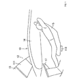
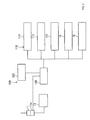
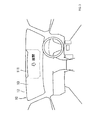
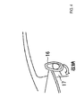
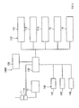
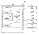
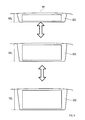
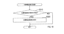
車両内における構成を示す説明面である。It is an explanatory surface which shows the structure in a vehicle. 第1実施形態における車両用体験装置の構成を示す説明図である。It is explanatory drawing which shows the structure of the experience device for a vehicle in 1st Embodiment. ディスプレイが展開される様子を示す説明図である。It is explanatory drawing which shows how the display is developed. インストルメントパネル内に収納されるハンドルを示す説明図である。It is explanatory drawing which shows the handle which is housed in an instrument panel. 第2実施形態における車両用体験装置の構成を示す説明図である。It is explanatory drawing which shows the structure of the experience device for a vehicle in 2nd Embodiment. 表示システムの構成を示すブロック図である。It is a block diagram which shows the structure of a display system. 車室内における有機ELディスプレイの配置を示す図である。It is a figure which shows the arrangement of the organic EL display in a vehicle interior. ディスプレイ展開処理を示すフローチャートである。It is a flowchart which shows the display expansion process. 通常展開長、二倍展開長および三倍展開長を示す図である。It is a figure which shows the normal expansion length, the double expansion length and the triple expansion length. 注意喚起表示処理を示すフローチャートである。It is a flowchart which shows the alert display process. 注意喚起表示の第1の具体例を示す図である。It is a figure which shows the 1st specific example of a warning display. 注意喚起表示の第2の具体例を示す図である。It is a figure which shows the 2nd specific example of a warning display.

以下に、図面を参照しながら本発明を実施するための複数の形態を説明する。各形態において先行する形態で説明した事項に対応する部分には同一の参照符号を付して重複する説明を省略する場合がある。各形態において構成の一部のみを説明している場合は、構成の他の部分については先行して説明した他の形態を適用することができる。各実施形態で具体的に組み合わせが可能であることを明示している部分同士の組み合わせばかりではなく、特に組み合わせに支障が生じなければ、明示していなくても実施形態同士を部分的に組み合せることも可能である。 A plurality of modes for carrying out the present invention will be described below with reference to the drawings. In each form, the same reference numerals may be attached to the parts corresponding to the items described in the preceding forms, and duplicate description may be omitted. When only a part of the configuration is described in each form, the other forms described above can be applied to the other parts of the configuration. Not only the combination of the parts that clearly indicate that the combination is possible in each embodiment, but also the combination of the embodiments is partially combined even if the combination is not specified if there is no particular problem in the combination. It is also possible.

(第1実施形態)
第1実施形態の車両用体験装置100を図1〜図4に示す。車両用体験装置100は、例えば、電気自動車(EV)やプラグインハイブリッド自動車(PHV)等のように、車両10のバッテリ11から供給される電力を受けて駆動する走行用の電動機(走行用モータ)を有する車両10に搭載されている。バッテリ11は、本発明の電源部に対応する。本実施形態では、ユーザが運転を行っていないとき、つまり、以下の充電ステーションに駐車してバッテリ11に充電を行う場合の例として説明する。
(First Embodiment)
The vehicle experience device 100 of the first embodiment is shown in FIGS. 1 to 4. The vehicle experience device 100 is a traveling electric motor (traveling motor) that is driven by receiving power supplied from the battery 11 of the vehicle 10, such as an electric vehicle (EV) or a plug-in hybrid vehicle (PHV). ) Is mounted on the vehicle 10. The battery 11 corresponds to the power supply unit of the present invention. In the present embodiment, an example will be described when the user is not driving, that is, when the battery 11 is charged by parking at the following charging station.

図1、図2に示すように、車両10には、駐車中にバッテリ11の充電を行う際に、例えば、全国の高速道路サービスエリア、ガソリンスタンド、自動車販売店、有料駐車場、あるいはショッピングセンター等に設置されている充電ステーションにおける充電器の充電コネクタ1を接続するための充電リッド11aが設けられている。充電コネクタ1は、充電器における電力をバッテリ11に供給する電力供給部である。充電リッド11aは、充電コネクタ1の受け部であり、車両側充電器を介してバッテリ11に接続されている。 As shown in FIGS. 1 and 2, when the battery 11 is charged while the vehicle is parked, for example, a highway service area, a gas station, a car dealer, a toll parking lot, or a shopping center nationwide. A charging lid 11a for connecting the charging connector 1 of the charger in the charging station installed in the above is provided. The charging connector 1 is a power supply unit that supplies electric power in the charger to the battery 11. The charging lid 11a is a receiving portion of the charging connector 1 and is connected to the battery 11 via a vehicle-side charger.

車両用体験装置100は、体験用機器110、入力部120、および制御部130等を備えている。
体験用機器110は、ユーザへの体験提供を可能とする機器であり、後述する制御部130によって、その作動が制御されるようになっている。体験用機器110は、例えば、ディスプレイ111、調光フィルム112、シート空調部113、低反発シート15、およびハンドル16等として設定することができる。
The vehicle experience device 100 includes an experience device 110, an input unit 120, a control unit 130, and the like.
The experience device 110 is a device that enables the experience to be provided to the user, and its operation is controlled by a control unit 130 described later. The experience device 110 can be set as, for example, a display 111, a light control film 112, a seat air conditioner 113, a memory foam sheet 15, a handle 16, and the like.

ディスプレイ111は、例えば、薄型の有機ELディスプレイ(OLED)が使用されており、ルーフ部12に収容可能となっている。ディスプレイ111は、本発明の画像を表示する表示部に対応する。通常運転時において、ディスプレイ111は、運転時のユーザの視界を妨げないように、下側となる一部が横長の帯状となってフロントウインドウ13の上側にせり出している。通常運転時においては、ディスプレイ111は、例えば、車両10の各種走行情報(走行速度、走行モード、走行距離、航続可能距離、バッテリ残量等)にかかる補助的な表示、あるいはカーナビゲーションシステムによる目的地案内情報の表示等を行うようになっている。 As the display 111, for example, a thin organic EL display (OLED) is used, and the display 111 can be accommodated in the roof portion 12. The display 111 corresponds to a display unit that displays the image of the present invention. During normal operation, the display 111 protrudes above the front window 13 in a horizontally long strip shape so as not to obstruct the user's field of view during operation. During normal driving, the display 111 is, for example, an auxiliary display related to various driving information (traveling speed, traveling mode, mileage, cruising range, remaining battery level, etc.) of the vehicle 10, or a purpose of the car navigation system. It is designed to display land guidance information.

また、バッテリ11の充電時においては、図3に示すように、ディスプレイ111は、ユーザの指示(指示信号)に基づき、全体がルーフ部12から更にせり出して、大画面を形成するようになっている。即ち、バッテリ11の充電時においては、ディスプレイ111は、通常運転時のユーザの視界を妨げる領域にまで至るように展開されるようになっている。ディスプレイ111は、上記の各種走行情報や、目的地案内情報の他にも、テレビ、DVD(映画)、ゲーム、チャット、パソコンソフト等の表示もできるようになっており、後述するように、主に充電時に利用可能となっている。 Further, when the battery 11 is being charged, as shown in FIG. 3, the entire display 111 protrudes further from the roof portion 12 based on a user's instruction (instruction signal) to form a large screen. There is. That is, when the battery 11 is being charged, the display 111 is expanded to reach an area that obstructs the user's field of vision during normal operation. In addition to the above-mentioned various driving information and destination guidance information, the display 111 can also display TV, DVD (movie), games, chat, personal computer software, etc., and as will be described later, the display 111 is mainly used. It is available when charging.

尚、上記のようにディスプレイ111を大画面展開したときに、例えば、ディスプレイ111にコントローラや、キーボード等を接続することで、ゲーム、チャット、パソコンソフトの実行等が可能となっている。 When the display 111 is expanded on a large screen as described above, for example, by connecting a controller, a keyboard, or the like to the display 111, it is possible to execute a game, chat, or personal computer software.

調光フィルム112は、例えば、車両10のフロントウインドウ13、サイドウインドウ14に設けられて、ユーザの指示(指示信号)に基づき、車室内への外光透過を制御(透過率可変による透過、遮光の制御)するようになっている。調光フィルム112を透過状態に設定することで、各ウインドウ13、14は、通常の透明なガラスのようになって、外部に対するユーザの視界が確保される。また、調光フィルム112を遮光状態に設定することで、各ウインドウ13、14には、あたかもブラインドが形成されたようになって、外部から車室内が視認できない(のぞかれない)ようになっている。 The dimming film 112 is provided on, for example, the front window 13 and the side window 14 of the vehicle 10 and controls the transmission of external light into the vehicle interior based on a user's instruction (instruction signal) (transmission by variable transmittance, shading). (Control of). By setting the light control film 112 in the transmissive state, the windows 13 and 14 become like ordinary transparent glass, and the user's field of view to the outside is secured. Further, by setting the light control film 112 to the light-shielding state, blinds are formed in each of the windows 13 and 14, so that the vehicle interior cannot be seen (looked out) from the outside. ing.

シート空調部113は、例えば、低反発シート15の座面の下側に、本体部となる送風機が設置されて、ユーザの指示(指示信号)に基づき、低反発シート15の座面や背もたれに複数設けられた空気通路を介して、車両用空調装置で空調された空気の一部を、シート15に座るユーザに対してスポット的に供給する空調部となっている。シート空調部113は、例えば、AI(人工知能)を備えており、車室内全体を空調するのではなく、ユーザを包み込むように空調する空調部となっている。 In the seat air-conditioning unit 113, for example, a blower serving as a main body is installed under the seat surface of the low-resilience seat 15, and based on a user's instruction (instruction signal), the seat air-conditioning unit 113 can be used on the seat surface or backrest of the low-resilience seat 15. It is an air conditioner that spot-supplies a part of the air conditioned by the vehicle air conditioner to the user sitting on the seat 15 through a plurality of air passages. The seat air-conditioning unit 113 is provided with, for example, AI (artificial intelligence), and is an air-conditioning unit that air-conditions the entire interior of the vehicle so as to wrap around the user.

低反発シート15は、背もたれに複数段階に調節可能なリクライニング機能が設けられて、座面や背もたれは、ユーザの体重を受けると沈み込んで、体重を分散して逃がすシートとなっている。低反発シート15は、ユーザの体重による反発が発生しにくくなっていることから、ユーザは自分の体重を感じにくく(無重力の感覚が得られるように)なっている。 The memory foam seat 15 is provided with a reclining function that can be adjusted in a plurality of stages on the backrest, and the seat surface and the backrest are seats that sink when the user's weight is received to disperse and release the weight. Since the low-resilience sheet 15 is less likely to cause repulsion due to the user's weight, the user is less likely to feel his / her weight (so that a feeling of weightlessness can be obtained).

ハンドル16は、図4に示すように、ユーザの指示(指示信号)に基づき、車両10のインストルメントパネル17側に収納可能となっており、収納された状態では、ユーザの膝元の空間が拡大されるようになっている。 As shown in FIG. 4, the steering wheel 16 can be stored on the instrument panel 17 side of the vehicle 10 based on the user's instruction (instruction signal), and in the stored state, the space around the user's knee is expanded. It is supposed to be done.

入力部120は、充電時にユーザが体験用機器110のうち、どの機器を作動させたいかを選択するためのスイッチ部となっている。入力部120は、例えば、タッチパネルスイッチ、メカスイッチ、あるいは音声入力スイッチ等として設けることができる。入力部120に入力されたユーザの指示信号は、後述する制御部130に出力されるようになっている。 The input unit 120 is a switch unit for the user to select which of the experience devices 110 he / she wants to operate at the time of charging. The input unit 120 can be provided as, for example, a touch panel switch, a mechanical switch, a voice input switch, or the like. The user's instruction signal input to the input unit 120 is output to the control unit 130, which will be described later.

制御部130は、入力部120からの指示信号に応じて、体験用機器110(111、112、113、15、16等)の作動を制御する制御手段となっている。また、制御部130は、充電リッド11aに充電コネクタ1が接続されている間は、バッテリ11に対する充電が実施されていると検出(認識)するようになっている。 The control unit 130 is a control means for controlling the operation of the experience device 110 (111, 112, 113, 15, 16, etc.) in response to the instruction signal from the input unit 120. Further, the control unit 130 detects (recognizes) that the battery 11 is being charged while the charging connector 1 is connected to the charging lid 11a.

尚、制御部130の一例は、少なくともプログラムを格納したメモリと、このプログラムを実行する少なくともひとつのプロセッサとを備えるコンピュータである。この場合、コンピュータは、CPU:Central Processing Unit、またはGPU:Graphics Processing Unitなどと呼ばれる少なくともひとつのプロセッサコアを備える。メモリは、記憶媒体とも呼ばれる。メモリは、プロセッサによって読み取り可能な「プログラムおよび/またはデータ」を非一時的に格納する非遷移的かつ実体的な記憶媒体である。記憶媒体は、半導体メモリ、磁気ディスク、または光学ディスクなどによって提供される。プログラムは、それ単体で、またはプログラムが格納された記憶媒体として流通する場合がある。 An example of the control unit 130 is a computer including at least a memory for storing a program and at least one processor for executing this program. In this case, the computer includes at least one processor core called a CPU: Central Processing Unit, a GPU: Graphics Processing Unit, or the like. Memory is also called a storage medium. Memory is a non-transitional and substantive storage medium that non-temporarily stores "programs and / or data" that can be read by a processor. The storage medium is provided by a semiconductor memory, a magnetic disk, an optical disk, or the like. The program may be distributed by itself or as a storage medium in which the program is stored.

車両用体験装置100の構成は、以上のようになっており、次に、車両用体験装置100の作動と作用効果について説明する。
まず、充電ステーションにおけるバッテリ11の充電時には、ユーザによって充電リッド11aに充電コネクタ1が接続される。制御部130は、充電コネクタ1が充電リッド11aに接続されることによって、充電が開始されたことを検出する。また、制御部130は、充電コネクタ1が充電リッド11aから外されることによって、充電が終了されたことを検出する。
The configuration of the vehicle experience device 100 is as described above. Next, the operation and operation / effect of the vehicle experience device 100 will be described.
First, when charging the battery 11 at the charging station, the user connects the charging connector 1 to the charging lid 11a. The control unit 130 detects that charging has started by connecting the charging connector 1 to the charging lid 11a. Further, the control unit 130 detects that charging has been completed by removing the charging connector 1 from the charging lid 11a.

そして、ユーザが、充電中に体験用機器110のいずれを作動させたいかを入力部120に入力すると、入力された指示信号は、制御部130に出力される。制御部130は、指示信号に基づいて、所定のモードで体験用機器110の作動を制御する。 Then, when the user inputs to the input unit 120 which of the experience devices 110 he / she wants to operate during charging, the input instruction signal is output to the control unit 130. The control unit 130 controls the operation of the experience device 110 in a predetermined mode based on the instruction signal.

例えば、ユーザからディスプレイ111を用いたテレビ放映、あるいはDVD(映画)の再生希望があると、制御部130は、ディスプレイ111をフロントウインドウ13の領域内に大きく展開させる(図3中の破線)。そして、制御部130は、希望のテレビ放映、あるいはDVD再生を行う。ユーザは、通常の車両10では見られない迫力ある大画面で、テレビやDVDを満喫(体験)することができる。尚、ユーザの指示がゲーム、チャット、パソコンソフト等であれば、制御部130は、ゲーム、チャット、パソコンソフト等の表示を行う。ユーザは、充電中にゲーム、チャット等を満喫する、あるいはパソコンソフトの実行により仕事(文章や説明資料等の作成)を行うこともできる。 For example, when the user requests TV broadcasting using the display 111 or playback of a DVD (movie), the control unit 130 expands the display 111 greatly within the area of the front window 13 (broken line in FIG. 3). Then, the control unit 130 broadcasts the desired television or reproduces the DVD. The user can enjoy (experience) a TV or a DVD on a powerful large screen that cannot be seen in a normal vehicle 10. If the user's instruction is a game, chat, personal computer software, or the like, the control unit 130 displays the game, chat, personal computer software, or the like. The user can enjoy games, chats, etc. while charging, or can perform work (creating sentences, explanatory materials, etc.) by executing the personal computer software.

また、ユーザから調光フィルム112を用いた各ウインドウ13、14の遮光の希望があると、制御部130は、調光フィルム112を遮光状態にする。これにより、車室内のプライベート感を高めることができる。更に、外部から車室内が容易にのぞかれないようにすることができる。例えば、充電ステーションが、駐車場の奥まった暗い場所にあって、不意に外部の人から車室内をのぞかれると、ユーザは極めて不安な気持ちを抱く。上記のように、調光フィルム112による各ウインドウ13、14を遮光することにより、ユーザは、不安無く充電中の時間を過ごすことが可能となる。 Further, when the user requests light shielding of the windows 13 and 14 using the light control film 112, the control unit 130 puts the light control film 112 in a light shielding state. As a result, the feeling of privacy in the passenger compartment can be enhanced. Further, it is possible to prevent the vehicle interior from being easily seen from the outside. For example, when a charging station is located in a dark place in the back of a parking lot and an outsider suddenly looks into the passenger compartment, the user feels extremely uneasy. As described above, by shading the windows 13 and 14 by the light control film 112, the user can spend the time during charging without anxiety.

また、ユーザからスポット空調の要求があると、制御部130は、シート空調部113を作動させる。シート空調部113は、ユーザを包み込むように空調して快適な温度調整を行う。尚、シート空調部113は、AI(人工知能)によって、現在使用しているユーザの特性(寒がり、暑がり、足部冷え症等)に合せて作動され、ユーザにとって快適な空調を実現できる。 Further, when the user requests spot air conditioning, the control unit 130 operates the seat air conditioning unit 113. The seat air-conditioning unit 113 air-conditions so as to wrap around the user and adjusts the temperature comfortably. The seat air-conditioning unit 113 is operated by AI (artificial intelligence) according to the characteristics of the user currently in use (cold, hot, cold feet, etc.), and can realize comfortable air-conditioning for the user.

また、ユーザから低反発シート15のリクライニング要求があると、制御部130は、ユーザの希望する角度に背もたれを倒す。これにより、ユーザがリラックスした姿勢を保つことができる。また、低反発シート15は、ユーザの体重による反発が発生しにくくなっていることから、ユーザは自分の体重を感じにくく(無重力の感覚が得られ)、まるで浮かんでいるかのようにくつろぎの時間を過ごすことができる。 Further, when the user requests the reclining of the low-resilience seat 15, the control unit 130 tilts the backrest at an angle desired by the user. This allows the user to maintain a relaxed posture. In addition, since the low-resilience sheet 15 is less likely to cause repulsion due to the user's weight, the user is less likely to feel his / her weight (a feeling of weightlessness is obtained), and a relaxing time as if he / she is floating. Can be spent.

また、ユーザからハンドル16の収納指示があると、制御部130は、ハンドル16をインストルメントパネル17内に収容する。これにより、ユーザの膝元の空間が拡大され、車室内におけるくつろぎの姿勢を邪魔されることがない。 Further, when the user gives an instruction to store the handle 16, the control unit 130 accommodates the handle 16 in the instrument panel 17. As a result, the space around the user's knee is expanded, and the relaxing posture in the vehicle interior is not disturbed.

以上のように、本実施形態によれば、充電時間中にユーザの指示に応じて、体験用機器110が制御部130によって所定のモードで作動制御されるので、ユーザは、車両内において、体験用機器110によって、充電待ちの時間に心地よいと感じる体験を得ることができる。 As described above, according to the present embodiment, the experience device 110 is operated and controlled by the control unit 130 in a predetermined mode according to the instruction of the user during the charging time, so that the user can experience in the vehicle. With the device 110, it is possible to obtain an experience that feels comfortable while waiting for charging.

(第2実施形態)
第2実施形態の車両用体験装置100Aを図5に示す。第2実施形態の車両用体験装置100Aは、上記第1実施形態の車両用体験装置100に対して、ユーザの状態を検出する状態検出部140を追加したものとしている。
(Second Embodiment)
The vehicle experience device 100A of the second embodiment is shown in FIG. The vehicle experience device 100A of the second embodiment adds a state detection unit 140 for detecting the user's state to the vehicle experience device 100 of the first embodiment.

状態検出部140は、例えば、ユーザの姿勢、あるいはユーザの体調等を検知する検知手段であり、カメラ141、シートセンサ142、生体センサ143等を用いることが可能である。 The state detection unit 140 is, for example, a detection means for detecting the posture of the user, the physical condition of the user, and the like, and a camera 141, a seat sensor 142, a biological sensor 143, and the like can be used.

カメラ141は、主にユーザを撮影することでユーザの姿勢(座り姿勢、リクライニング姿勢、あるいは顔の向き等)にかかるデータを取得して、取得したデータを制御部130に出力するようになっている。カメラ141は、例えば、車両10にDSM(ドライバーステータスモニター)システムが搭載されている場合であれば、DSMシステムのカメラを流用することができる。 The camera 141 acquires data related to the user's posture (sitting posture, reclining posture, face orientation, etc.) mainly by photographing the user, and outputs the acquired data to the control unit 130. There is. As the camera 141, for example, if the vehicle 10 is equipped with a DSM (driver status monitor) system, the camera of the DSM system can be diverted.

シートセンサ142は、低反発シート15の座面や背もたれに複数分布するように設けられて、ユーザの体重分布データを取得するセンサであり、取得したデータを制御部130に出力するようになっている。 The seat sensor 142 is provided so as to be distributed on the seat surface and the backrest of the low-resilience seat 15 so as to acquire a plurality of user weight distribution data, and the acquired data is output to the control unit 130. There is.

生体センサ143は、ユーザに接触可能なように、例えば、低反発シート15の座面等に設けられている。生体センサ143は、例えば、ユーザの体温、脈拍数(心拍数)等を計測し、計測結果を制御部130に出力する。尚、生体センサ143は、血圧、脳波、および発汗量等、他の生体情報を計測するものであってもよい。 The biosensor 143 is provided on, for example, the seating surface of the low-resilience seat 15 so that it can be contacted by the user. The biosensor 143 measures, for example, the user's body temperature, pulse rate (heart rate), and the like, and outputs the measurement result to the control unit 130. The biological sensor 143 may measure other biological information such as blood pressure, brain waves, and sweating amount.

そして、制御部130は、状態検出部140で検知されたユーザの状態から、ユーザの要望を予測して、体験用機器110の作動を制御する。
例えば、ディスプレイ111を展開した状態で、制御部130は、状態検出部140(カメラ141、あるいはシートセンサ142)から、ユーザの姿勢あるいは顔の向きを判定して、ディスプレイ111の表示面の向き(表示角度)をユーザが見やすい向きに調整する。
Then, the control unit 130 predicts the user's request from the user's state detected by the state detection unit 140, and controls the operation of the experience device 110.
For example, with the display 111 expanded, the control unit 130 determines the posture or face orientation of the user from the state detection unit 140 (camera 141 or seat sensor 142), and the orientation of the display surface of the display 111 ( Adjust the display angle) so that the user can easily see it.

あるいは、シート空調部113を作動させた状態で、制御部130は、状態検出部140(生体センサ143)から、ユーザの体温に基づいて、スポット空調の設定温度を調整する。あるいは、制御部130は、状態検出部140(生体センサ143)から、ユーザの脈拍数(心拍数)に基づいて(脈拍数が所定値より高いと)、調光フィルム112の遮光を行う。 Alternatively, with the seat air-conditioning unit 113 activated, the control unit 130 adjusts the set temperature of the spot air-conditioning from the state detection unit 140 (biological sensor 143) based on the user's body temperature. Alternatively, the control unit 130 shields the light control film 112 from the state detection unit 140 (biological sensor 143) based on the user's pulse rate (heart rate) (when the pulse rate is higher than a predetermined value).

以上のように、本実施形態では、ユーザの姿勢、あるいはユーザの体調から、ユーザの要望を予測して、制御部130は、体験用機器110の作動を制御するので、ユーザ体験における感動(体験サービスに対する満足度)をより高めることができる。 As described above, in the present embodiment, the control unit 130 controls the operation of the experience device 110 by predicting the user's request from the user's posture or the user's physical condition, so that the user experience is impressed (experience). Satisfaction with the service) can be further enhanced.

(第3実施形態)
以下に本開示の第3実施形態を図面とともに説明する。
第3実施形態の表示システム200は、自動運転および手動運転の両方が可能な自動運転車両に搭載され、図6に示すように、表示制御装置201と、有機ELディスプレイ202と、展開装置203と、再生装置204と、チューナ205と、ドライバーステータスモニター206(以下、DSM206)と、操作スイッチ207とを備える。DSMは、Driver Status Monitorの略である。以下、表示システム200を搭載している車両を自車両MCという。なお、自車両MCは、図6に示しておらず、図7に示している。
(Third Embodiment)
The third embodiment of the present disclosure will be described below together with the drawings.
The display system 200 of the third embodiment is mounted on an autonomous driving vehicle capable of both automatic driving and manual driving, and as shown in FIG. 6, the display control device 201, the organic EL display 202, and the deploying device 203 , Reproduction device 204, tuner 205, driver status monitor 206 (hereinafter, DSM206), and operation switch 207. DSM is an abbreviation for Driver Status Monitor. Hereinafter, the vehicle equipped with the display system 200 is referred to as the own vehicle MC. The own vehicle MC is not shown in FIG. 6, but is shown in FIG.

表示制御装置201は、制御部211と、表示制御装置201の外部と制御部211との間で信号の入出力を行わせるための外部入出力回路212とを備える。
表示制御装置201は、CPU221、ROM222およびRAM223等を備えたマイクロコンピュータを中心に構成された電子制御装置である。マイクロコンピュータの各種機能は、CPU221が非遷移的実体的記録媒体に格納されたプログラムを実行することにより実現される。この例では、ROM222が、プログラムを格納した非遷移的実体的記録媒体に該当する。また、このプログラムの実行により、プログラムに対応する方法が実行される。なお、CPU221が実行する機能の一部または全部を、一つあるいは複数のIC等によりハードウェア的に構成してもよい。また、表示制御装置201を構成するマイクロコンピュータの数は1つでも複数でもよい。
The display control device 201 includes a control unit 211 and an external input / output circuit 212 for causing signals to be input / output between the outside of the display control device 201 and the control unit 211.
The display control device 201 is an electronic control device mainly composed of a microcomputer provided with a CPU 221 and a ROM 222, a RAM 223, and the like. Various functions of the microcomputer are realized by the CPU 221 executing a program stored in a non-transitional substantive recording medium. In this example, ROM 222 corresponds to a non-transitional substantive recording medium in which a program is stored. In addition, by executing this program, the method corresponding to the program is executed. A part or all of the functions executed by the CPU 221 may be configured in hardware by one or a plurality of ICs or the like. Further, the number of microcomputers constituting the display control device 201 may be one or a plurality.

制御部211は、CPU221と、ROM222と、RAM223と、入出力ポート224と、CAN通信部225と、広域無線通信部226と、これらを相互に接続するバスライン227とを備える。CANは、Controller Area Networkの略である。CANは登録商標である。 The control unit 211 includes a CPU 221, a ROM 222, a RAM 223, an input / output port 224, a CAN communication unit 225, a wide area wireless communication unit 226, and a bus line 227 that connects them to each other. CAN is an abbreviation for Controller Area Network. CAN is a registered trademark.

CPU221は、ROM222に記憶されたプログラムに基づいて、表示制御装置201を制御するための各種処理を実行する。ROM222は、不揮発性メモリであり、CPU41が実行するプログラムと、プログラムの実行時に参照されるデータとを記憶する。RAM223は、揮発性メモリであり、CPU221の演算結果等を一時的に記憶する。 The CPU 221 executes various processes for controlling the display control device 201 based on the program stored in the ROM 222. The ROM 222 is a non-volatile memory, and stores a program executed by the CPU 41 and data referred to when the program is executed. The RAM 223 is a volatile memory and temporarily stores the calculation result of the CPU 221 and the like.

入出力ポート224は、制御部211の外部と制御部211との間で信号の入出力を行わせるための回路である。
CAN通信部225は、CAN通信プロトコルに従って、車両に搭載された複数の車載装置(例えば、電子制御装置およびセンサ等)との間でデータ通信を行う。
The input / output port 224 is a circuit for inputting / outputting signals between the outside of the control unit 211 and the control unit 211.
The CAN communication unit 225 performs data communication with a plurality of in-vehicle devices (for example, electronic control devices and sensors) mounted on the vehicle according to the CAN communication protocol.

広域無線通信部226は、広域無線通信網を介して、車両の外部に設置された通信装置との間でデータ通信を行う。
有機ELディスプレイ202は、複数の有機EL素子が行列状に配置されて、可撓性を有する薄い板状に形成された表示装置である。
The wide area wireless communication unit 226 performs data communication with a communication device installed outside the vehicle via the wide area wireless communication network.
The organic EL display 202 is a display device in which a plurality of organic EL elements are arranged in a matrix to form a flexible thin plate.

展開装置203は、駆動源となるモータと、モータの駆動力を有機ELディスプレイ202へ伝達するギア列とを備える。展開装置203は、図7に示す車両のルーフ部RFとフロントウインドウFWとの境界付近におけるルーフ部RF内に設置されている。 The deploying device 203 includes a motor as a drive source and a gear train that transmits the driving force of the motor to the organic EL display 202. The deploying device 203 is installed in the roof portion RF near the boundary between the roof portion RF of the vehicle and the front window FW shown in FIG. 7.

図7に示すように、展開装置203は、ルーフ部RF内に収納されている有機ELディスプレイ202を、ルーフ部RFとフロントウインドウFWとの境界付近におけるルーフ部RF側に形成された図示しない開口部から引き出されるように移動させる。これにより、展開装置203は、運転席DSに着座している運転者DRに対してフロントウインドウFWを隠すように有機ELディスプレイ202を展開する。 As shown in FIG. 7, the deploying device 203 opens an organic EL display 202 housed in the roof portion RF on the roof portion RF side near the boundary between the roof portion RF and the front window FW (not shown). Move it so that it is pulled out from the part. As a result, the deploying device 203 deploys the organic EL display 202 so as to hide the front window FW from the driver DR seated in the driver's seat DS.

また展開装置203は、フロントウインドウFWを覆い隠すように展開している有機ELディスプレイ202を、開口部を通ってルーフ部RF内に収納されるように移動させることができる。 Further, the deploying device 203 can move the organic EL display 202 deployed so as to cover the front window FW so as to be housed in the roof portion RF through the opening.

再生装置204は、映像記録媒体に記録されたデータを読み込んで、読み込んだデータに基づいて音声信号および映像信号を生成し、生成した音声信号および映像信号を出力する。 The playback device 204 reads the data recorded on the video recording medium, generates an audio signal and a video signal based on the read data, and outputs the generated audio signal and the video signal.

チューナ205は、AM放送、FM放送およびテレビ放送の放送信号を受信して、受信した放送信号に基づいて音声信号および映像信号を生成し、生成した音声信号および映像信号を出力する。 The tuner 205 receives broadcast signals of AM broadcast, FM broadcast, and television broadcast, generates audio signals and video signals based on the received broadcast signals, and outputs the generated audio signals and video signals.

DSM206は、運転者DRの顔を撮影した顔画像の画像解析により、運転者DRの状態を検出する。
操作スイッチ207は、例えばセンターコンソールに設置され、車両の乗員が操作スイッチ207を操作することにより、各種指示を表示制御装置201へ出力する。
The DSM 206 detects the state of the driver DR by image analysis of the face image of the driver DR's face.
The operation switch 207 is installed on the center console, for example, and the occupant of the vehicle operates the operation switch 207 to output various instructions to the display control device 201.

このように構成された表示システム200において、制御部211のCPU221は、ディスプレイ展開処理および注意喚起表示処理を実行する。
まず、制御部211のCPU221が実行するディスプレイ展開処理の手順を説明する。ディスプレイ展開処理は、制御部211の動作中において繰り返し実行される処理である。
In the display system 200 configured in this way, the CPU 221 of the control unit 211 executes the display expansion process and the alert display process.
First, the procedure of the display expansion process executed by the CPU 221 of the control unit 211 will be described. The display expansion process is a process that is repeatedly executed during the operation of the control unit 211.

ディスプレイ展開処理が実行されると、CPU221は、図8に示すように、まずS10にて、自車両MCが停車中であるか否かを判断する。具体的には、CPU221は、CAN通信部225を介して、車両に搭載された車載装置から、自車両MCの走行速度(以下、車速)を示す車速情報を取得し、車速情報が示す車速に基づいて、自車両MCが停車中であるか否かを判断する。 When the display expansion process is executed, the CPU 221 first determines in S10 whether or not the own vehicle MC is stopped, as shown in FIG. Specifically, the CPU 221 acquires vehicle speed information indicating the traveling speed (hereinafter referred to as vehicle speed) of the own vehicle MC from the in-vehicle device mounted on the vehicle via the CAN communication unit 225, and obtains the vehicle speed indicated by the vehicle speed information. Based on this, it is determined whether or not the own vehicle MC is stopped.

ここで、自車両MCが停車中でない場合には、CPU221は、S40に移行する。一方、自車両MCが停車中である場合には、CPU221は、S20にて、操作スイッチ207から低速指示が入力されているか否かを判断する。低速指示は、有機ELディスプレイ202を展開または収納するための有機ELディスプレイ202の移動を低速で行うことを指示する。 Here, when the own vehicle MC is not stopped, the CPU 221 shifts to S40. On the other hand, when the own vehicle MC is stopped, the CPU 221 determines in S20 whether or not a low speed instruction is input from the operation switch 207. The low-speed instruction indicates that the organic EL display 202 for deploying or storing the organic EL display 202 is moved at a low speed.

ここで、低速指示が入力されている場合には、CPU221は、S30にて、RAM223に設けられた高速移動フラグF1をクリアして、S50に移行する。以下の説明において、フラグをセットするとは、そのフラグの値を1にすることを示し、フラグをクリアするとは、そのフラグの値を0にすることを示す。 Here, when the low-speed instruction is input, the CPU 221 clears the high-speed movement flag F1 provided in the RAM 223 in S30 and shifts to S50. In the following description, setting a flag indicates that the value of the flag is set to 1, and clearing the flag indicates that the value of the flag is set to 0.

一方、低速指示が入力されていない場合には、CPU221は、操作スイッチ207から高速指示が入力されていると判断して、S40に移行する。高速指示は、有機ELディスプレイ202を展開または収納するための有機ELディスプレイ202の移動を高速で行うことを指示する。 On the other hand, when the low-speed instruction is not input, the CPU 221 determines that the high-speed instruction is input from the operation switch 207, and shifts to S40. The high-speed instruction indicates that the organic EL display 202 for deploying or storing the organic EL display 202 is moved at high speed.

S40に移行すると、CPU221は、高速移動フラグF1をセットして、S50に移行する。
S50に移行すると、CPU221は、自車両MCが手動運転中であるか否かを判断する。具体的には、CPU221は、CAN通信部225を介して、自車両MCに搭載された自動運転制御装置から、自車両MCの運転モードを示す運転モード情報を取得し、運転モード情報が示す運転モードに基づいて、自車両MCが手動運転中であるか否かを判断する。運転モード情報は、少なくとも、自車両MCが、手動運転中であるか、レベル2の自動運転中であるか、レベル3の自動運転中であるか、充電中であるかを示す。
When shifting to S40, the CPU 221 sets the high-speed movement flag F1 and shifts to S50.
After shifting to S50, the CPU 221 determines whether or not the own vehicle MC is in manual operation. Specifically, the CPU 221 acquires the operation mode information indicating the operation mode of the own vehicle MC from the automatic operation control device mounted on the own vehicle MC via the CAN communication unit 225, and the operation indicated by the operation mode information. Based on the mode, it is determined whether or not the own vehicle MC is in manual operation. The operation mode information indicates at least whether the own vehicle MC is in manual operation, in level 2 automatic operation, in level 3 automatic operation, or in charging.

ここで、自車両MCが手動運転中である場合には、CPU221は、S60にて、RAM223に設けられた展開レベルLEVELに1を格納して、S140に移行する。
一方、自車両MCが手動運転中でない場合には、CPU221は、S70にて、取得した運転モード情報に基づいて、自車両MCがレベル2の自動運転中であるか否かを判断する。ここで、レベル2の自動運転中である場合には、CPU221は、S80にて、展開レベルLEVELに2を格納して、S140に移行する。
Here, when the own vehicle MC is in manual operation, the CPU 221 stores 1 in the expansion level LEVEL provided in the RAM 223 in S60, and shifts to S140.
On the other hand, when the own vehicle MC is not in manual operation, the CPU 221 determines in S70 whether or not the own vehicle MC is in level 2 automatic operation based on the acquired operation mode information. Here, when the level 2 automatic operation is in progress, the CPU 221 stores 2 in the expansion level LEVEL in S80 and shifts to S140.

一方、自車両MCがレベル2の自動運転中でない場合には、CPU221は、S90にて、取得した運転モード情報に基づいて、自車両MCがレベル3の自動運転中であるか否かを判断する。ここで、レベル3の自動運転中である場合には、CPU221は、S100にて、展開レベルLEVELに3を格納して、S140に移行する。 On the other hand, when the own vehicle MC is not in the level 2 automatic driving, the CPU 221 determines in S90 whether or not the own vehicle MC is in the level 3 automatic driving based on the acquired driving mode information. To do. Here, when the level 3 automatic operation is in progress, the CPU 221 stores 3 in the expansion level LEVEL in S100 and shifts to S140.

一方、自車両MCがレベル3の自動運転中でない場合には、CPU221は、S110にて、取得した運転モード情報に基づいて、自車両MCが充電中であるか否かを判断する。ここで、充電中である場合には、CPU221は、S120にて、展開レベルLEVELに3を格納して、S140に移行する。 On the other hand, when the own vehicle MC is not in the level 3 automatic operation, the CPU 221 determines in S110 whether or not the own vehicle MC is charging based on the acquired operation mode information. Here, when charging is in progress, the CPU 221 stores 3 in the expansion level LEVEL in S120 and shifts to S140.

一方、自車両MCが充電中でない場合には、CPU221は、S130にて、展開レベルLEVELに1を格納して、S140に移行する。
そして、S140に移行すると、CPU221は、S140にて、展開レベルLEVELに格納されている値が3であるか否かを判断する。ここで、展開レベルLEVELに格納されている値が3である場合には、CPU221は、S150にて、DSM206から、運転席DSのリクライニング角度を示すリクライニング情報を取得する。DSM206は、運転者DRの顔を撮影した顔画像の画像解析により、運転者DRの視線方向を検出し、この視線方向に基づいてリクライニング角度を算出する。
On the other hand, when the own vehicle MC is not charging, the CPU 221 stores 1 in the expansion level LEVEL in S130 and shifts to S140.
Then, upon shifting to S140, the CPU 221 determines in S140 whether or not the value stored in the expansion level LEVEL is 3. Here, when the value stored in the expansion level LEVEL is 3, the CPU 221 acquires the reclining information indicating the reclining angle of the driver's seat DS from the DSM 206 in S150. The DSM 206 detects the line-of-sight direction of the driver DR by image analysis of the face image of the driver DR's face, and calculates the reclining angle based on the line-of-sight direction.

さらにCPU221は、S160にて、取得したリクライニング情報が示すリクライニング角度と、リクライニング角度と展開増減量との対応関係が予め設定された展開増減量マップとに基づいて、展開増減量を設定し、S180に移行する。展開増減量マップは、ROM222に記憶されている。 Further, the CPU 221 sets the expansion increase / decrease amount based on the reclining angle indicated by the reclining information acquired in S160 and the expansion increase / decrease amount map in which the correspondence between the reclining angle and the expansion increase / decrease amount is set in advance, and S180. Move to. The expansion increase / decrease amount map is stored in ROM 222.

またS140にて、展開レベルLEVELに格納されている値が3でない場合には、CPU221は、S170にて、展開増減量を0に設定し、S180に移行する。
S180に移行すると、CPU221は、高速移動フラグF1と、展開レベルLEVELと、展開増減量とに基づいて、有機ELディスプレイ202を展開し、ディスプレイ展開処理を終了する。
If the value stored in the expansion level LEVEL is not 3 in S140, the CPU 221 sets the expansion increase / decrease amount to 0 in S170 and shifts to S180.
After shifting to S180, the CPU 221 expands the organic EL display 202 based on the high-speed movement flag F1, the expansion level LEVEL, and the expansion increase / decrease amount, and ends the display expansion process.

具体的には、CPU221は、展開レベルLEVELが1である場合には、図9に示すように、有機ELディスプレイ202の下端とルーフ部RFとの間の距離が、通常展開長NELとなるように、有機ELディスプレイ202を展開する。通常展開長NELは、一般的なバックミラーの縦方向長さと略等しい長さである。 Specifically, when the expansion level LEVEL is 1, the CPU 221 has a normal expansion length NEL so that the distance between the lower end of the organic EL display 202 and the roof portion RF is the normal expansion length NEL, as shown in FIG. The organic EL display 202 is developed. The normal deployment length NEL is a length substantially equal to the vertical length of a general rearview mirror.

またCPU221は、展開レベルLEVELが2である場合には、有機ELディスプレイ202の下端とルーフ部RFとの間の距離が、二倍展開長DELとなるように、有機ELディスプレイ202を展開する。二倍展開長DELは、通常展開長NELの2倍の長さである。 Further, when the expansion level LEVEL is 2, the CPU 221 expands the organic EL display 202 so that the distance between the lower end of the organic EL display 202 and the roof portion RF is a double expansion length DEL. The double unfolded length DEL is twice as long as the normal unfolded length NEL.

またCPU221は、展開レベルLEVELが3である場合には、有機ELディスプレイ202の下端とルーフ部RFとの間の距離が、三倍展開長TELと展開増減量との加算値となるように、有機ELディスプレイ202を展開する。従って、有機ELディスプレイ202の下端とルーフ部RFとの間の距離は、展開増減量が正値である場合には三倍展開長TELより長くなり、展開増減量が負値である場合には三倍展開長TELより短くなる。三倍展開長TELは、通常展開長NELの3倍の長さである。 Further, when the expansion level LEVEL is 3, the CPU 221 is set so that the distance between the lower end of the organic EL display 202 and the roof portion RF is the sum of the triple expansion length TEL and the expansion increase / decrease amount. The organic EL display 202 is developed. Therefore, the distance between the lower end of the organic EL display 202 and the roof portion RF is longer than the triple expansion length TEL when the expansion increase / decrease amount is a positive value, and when the expansion increase / decrease amount is a negative value. It is shorter than the triple expansion length TEL. The triple unfolded length TEL is three times as long as the normal unfolded length NEL.

表示制御装置201は、自車両MCが手動運転中である場合には、自車両MCの後部に設置されて自車両MCの後方を撮影する後方カメラで撮影した画像を有機ELディスプレイ202に表示する。また表示制御装置201は、後方カメラで撮影した画像に車両が映っている場合には、車両の位置を強調表示するために検知マーカーを有機ELディスプレイ202に表示する。 When the own vehicle MC is in manual operation, the display control device 201 is installed at the rear of the own vehicle MC and displays an image taken by the rear camera that takes a picture of the rear of the own vehicle MC on the organic EL display 202. .. Further, when the vehicle is reflected in the image taken by the rear camera, the display control device 201 displays a detection marker on the organic EL display 202 in order to highlight the position of the vehicle.

表示制御装置201は、高速移動フラグF1がセットされている場合には、予め設定された高速移動速度で、有機ELディスプレイ202を展開または収納するように有機ELディスプレイ202を移動させる。 When the high-speed movement flag F1 is set, the display control device 201 moves the organic EL display 202 so as to deploy or store the organic EL display 202 at a preset high-speed movement speed.

表示制御装置201は、高速移動フラグF1がクリアされている場合には、高速移動速度より小さくなるように設定された低速移動速度で、有機ELディスプレイ202を展開または収納するように有機ELディスプレイ202を移動させる。 When the high-speed movement flag F1 is cleared, the display control device 201 deploys or stores the organic EL display 202 at a low-speed movement speed set to be smaller than the high-speed movement speed. To move.

表示制御装置201は、自車両MCが、レベル3の自動運転中、駐停車中または充電中である場合には、エンタメ映像(例えば、動画またはゲーム画像)、ウェブ会議映像、または、自動運転制御情報を有機ELディスプレイ202に表示する。エンタメ映像は、再生装置204またはチューナ205で生成された映像信号が表示制御装置201に入力されることにより有機ELディスプレイ202に表示される。ウェブ会議映像は、表示制御装置201が広域無線通信部226を介して映像情報を受信することにより有機ELディスプレイ202に表示される。自動運転制御情報は、表示制御装置201がCAN通信部225を介して自動運転制御装置から自動運転制御情報を受信することにより有機ELディスプレイ202に表示される。 When the own vehicle MC is in level 3 automatic driving, parked / stopped, or charging, the display control device 201 provides entertainment video (for example, video or game image), web conference video, or automatic driving control. The information is displayed on the organic EL display 202. The entertainment video is displayed on the organic EL display 202 when the video signal generated by the playback device 204 or the tuner 205 is input to the display control device 201. The web conference video is displayed on the organic EL display 202 when the display control device 201 receives the video information via the wide area wireless communication unit 226. The automatic operation control information is displayed on the organic EL display 202 when the display control device 201 receives the automatic operation control information from the automatic operation control device via the CAN communication unit 225.

なお、表示制御装置201は、自車両MCがレベル3の自動運転中である場合に、後方カメラで撮影した画像を有機ELディスプレイ202に表示するようにしてもよい。
有機ELディスプレイ202は、図7に示すように、フロントウインドウFWを覆い隠すように展開しているときには、表示画面が湾曲している。このため、有機ELディスプレイ202の表示画面が車室側へ向いている角度は、展開増減量に応じて変化する。
The display control device 201 may display the image taken by the rear camera on the organic EL display 202 when the own vehicle MC is in the level 3 automatic driving.
As shown in FIG. 7, the display screen of the organic EL display 202 is curved when it is deployed so as to cover the front window FW. Therefore, the angle at which the display screen of the organic EL display 202 faces the vehicle interior side changes according to the amount of expansion / decrease.

次に、制御部211のCPU221が実行する注意喚起表示処理の手順を説明する。注意喚起表示処理は、制御部211の動作中において繰り返し実行される処理である。
注意喚起表示処理が実行されると、CPU221は、図10に示すように、まずS310にて、予め設定された注意喚起表示条件が成立したか否かを判断する。注意喚起表示条件は、少なくとも、以下の第1表示条件および第2表示条件を含む。第1表示条件は、運転者DRの自宅に設置されている監視装置から、広域無線通信部226を介して、宅配物が到着した旨を示す宅配便到着通知を受信することである。第2表示条件は、自車両MCに搭載された自動運転制御装置から、CAN通信部225を介して、自動運転の終了を予告する終了予告通知を受信することである。
Next, the procedure of the warning display process executed by the CPU 221 of the control unit 211 will be described. The alert display process is a process that is repeatedly executed during the operation of the control unit 211.
When the alert display process is executed, the CPU 221 first determines in S310 whether or not the preset alert display condition is satisfied, as shown in FIG. The alert display condition includes at least the following first display condition and second display condition. The first display condition is to receive a courier arrival notification indicating that the courier has arrived from the monitoring device installed at the driver's DR's home via the wide area wireless communication unit 226. The second display condition is to receive the end notice notification for notifying the end of the automatic driving from the automatic driving control device mounted on the own vehicle MC via the CAN communication unit 225.

ここで、注意喚起表示条件が成立していない場合には、CPU221は、注意喚起表示処理を終了する。一方、注意喚起表示条件が成立した場合には、CPU221は、S320にて、成立した注意喚起表示条件の内容に応じて、予め設定された注意喚起画像を有機ELディスプレイ202に表示し、注意喚起表示処理を終了する。 Here, if the alert display condition is not satisfied, the CPU 221 ends the alert display process. On the other hand, when the alert display condition is satisfied, the CPU 221 displays a preset alert image on the organic EL display 202 according to the content of the established alert display condition in S320 to alert the user. End the display process.

例えば、第1表示条件が成立した場合には、CPU221は、自宅に設置されている監視装置から、自宅の玄関前にいる宅配人の顔を撮影した映像を示す映像情報と、宅配人が発話した音声を示す音声情報とを、広域無線通信部226を介して、受信する。そしてCPU221は、図11に示すように、受信した映像情報が示す映像を有機ELディスプレイ202に表示し、受信した音声情報が示す音声を車室内のスピーカから出力する。 For example, when the first display condition is satisfied, the CPU 221 uses a monitoring device installed at home to provide video information showing an image of the face of the delivery person in front of the front door of the house, and the delivery person speaks. The voice information indicating the voice is received via the wide area wireless communication unit 226. Then, as shown in FIG. 11, the CPU 221 displays the video indicated by the received video information on the organic EL display 202, and outputs the voice indicated by the received voice information from the speaker in the vehicle interior.

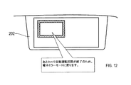
また、第2表示条件が成立した場合には、CPU221は、図12に示すように、終了予告通知の内容を示す画像を有機ELディスプレイ202に表示し、終了予告通知の内容を示す音声を車室内のスピーカから出力する。終了予告通知の内容は、例えば、あと2kmで自動運転区間が終了するために電子ミラーモードに戻ることである。電子ミラーモードは、有機ELディスプレイ202の縦方向長さを通常展開長NELにするモードである。 When the second display condition is satisfied, the CPU 221 displays an image showing the content of the end notice notification on the organic EL display 202 as shown in FIG. 12, and outputs a voice indicating the content of the end notice notification to the vehicle. Output from the speaker in the room. The content of the end notice is, for example, to return to the electronic mirror mode in order to end the automatic driving section in 2 km. The electronic mirror mode is a mode in which the vertical length of the organic EL display 202 is set to the normal unfolded length NEL.

このように構成された表示システム200の表示制御装置201は、自動走行機能を有する自車両MCの運転状態に応じて、有機ELディスプレイ202を展開させる展開量を変化させる。本実施形態における運転状態は、手動運転中、レベル2の自動運転中、レベル3の自動運転中および充電中を含む。これにより、表示システム200は、有機ELディスプレイ202の表示画面を、自車両MCの運転状態に応じた適切な大きさにすることができる。 The display control device 201 of the display system 200 configured in this way changes the deployment amount of the organic EL display 202 to be deployed according to the operating state of the own vehicle MC having the automatic traveling function. The operating state in the present embodiment includes manual operation, level 2 automatic operation, level 3 automatic operation, and charging. As a result, the display system 200 can make the display screen of the organic EL display 202 an appropriate size according to the operating state of the own vehicle MC.

また表示制御装置201は、自車両MCの車室内の状態に応じて、有機ELディスプレイ202の表示画面の角度を変化させる。本実施形態における車室内の状態は、運転席DSのリクライニング角度である。これにより、表示システム200は、車室内の状態に応じて、有機ELディスプレイ202の表示画面を自車両MCの乗員に見易くすることができる。 Further, the display control device 201 changes the angle of the display screen of the organic EL display 202 according to the state of the vehicle interior of the own vehicle MC. The state of the vehicle interior in this embodiment is the reclining angle of the driver's seat DS. As a result, the display system 200 can make the display screen of the organic EL display 202 easier for the occupants of the own vehicle MC to see according to the state of the vehicle interior.

また表示制御装置201は、予め設定された注意喚起表示条件が成立した場合に、注意喚起表示条件に応じて予め設定された注意喚起画像を有機ELディスプレイ202に表示する。これにより、表示システム200は、有機ELディスプレイ202を見ている自車両MCの乗員に対して、必要に応じて注意喚起を行うことができる。 Further, when the preset alert display condition is satisfied, the display control device 201 displays the alert image preset according to the alert display condition on the organic EL display 202. As a result, the display system 200 can alert the occupants of the own vehicle MC who are looking at the organic EL display 202, if necessary.

また表示制御装置201は、有機ELディスプレイ202をルーフ部RFから展開したりルーフ部RFに収納したりするために有機ELディスプレイ202を移動させる移動速度を、自車両MCの状態に応じて変化させる。本実施形態における自車両MCの状態は、走行中および停車中を含む。これにより、表示システム200は、自車両MCの状態に応じた適切な移動速度で有機ELディスプレイ202を展開したり収納したりすることができる。 Further, the display control device 201 changes the moving speed at which the organic EL display 202 is moved in order to expand the organic EL display 202 from the roof portion RF or store it in the roof portion RF according to the state of the own vehicle MC. .. The state of the own vehicle MC in the present embodiment includes running and stopped. As a result, the display system 200 can deploy and store the organic EL display 202 at an appropriate moving speed according to the state of the own vehicle MC.

以上説明した実施形態において、表示システム200は車両用体験装置に相当し、自車両MCは車両に相当し、表示制御装置201は制御部に相当し、有機ELディスプレイ202は体験用機器および表示部に相当する。
(その他の実施形態)
この明細書および図面等における開示は、例示された実施形態に制限されない。開示は、例示された実施形態と、それらに基づく当業者による変形態様を包含する。例えば、開示は、実施形態において示された部品および/または要素の組み合わせに限定されない。開示は、多様な組み合わせによって実施可能である。開示は、実施形態に追加可能な追加的な部分をもつことができる。開示は、実施形態の部品および/または要素が省略されたものを包含する。開示は、ひとつの実施形態と他の実施形態との間における部品および/または要素の置き換え、または組み合わせを包含する。開示される技術的範囲は、実施形態の記載に限定されない。開示されるいくつかの技術的範囲は、請求の範囲の記載によって示され、更に請求の範囲の記載と均等の意味および範囲内での全ての変更を含むものと解されるべきである。
In the embodiment described above, the display system 200 corresponds to the vehicle experience device, the own vehicle MC corresponds to the vehicle, the display control device 201 corresponds to the control unit, and the organic EL display 202 corresponds to the experience device and the display unit. Corresponds to.
(Other embodiments)
Disclosure in this specification, drawings and the like is not limited to the illustrated embodiments. The disclosure includes exemplary embodiments and modifications by those skilled in the art based on them. For example, disclosure is not limited to the parts and / or element combinations shown in the embodiments. Disclosure can be carried out in various combinations. The disclosure can have additional parts that can be added to the embodiment. The disclosure includes the parts and / or elements of the embodiment omitted. Disclosures include replacement or combination of parts and / or elements between one embodiment and another. The technical scope disclosed is not limited to the description of the embodiments. Some technical scopes disclosed are indicated by the claims description and should be understood to include all modifications within the meaning and scope equivalent to the claims description.

本開示に記載の制御部130およびその手法は、コンピュータプログラムにより具体化された一つないしは複数の機能を実行するようにプログラムされたプロセッサを構成する専用コンピュータにより、実現されてもよい。あるいは、本開示に記載の装置およびその手法は、専用ハードウエア論理回路により、実現されてもよい。もしくは、本開示に記載の装置およびその手法は、コンピュータプログラムを実行するプロセッサと一つ以上のハードウエア論理回路との組み合わせにより構成された一つ以上の専用コンピュータにより、実現されてもよい。また、コンピュータプログラムは、コンピュータにより実行されるインストラクションとして、コンピュータ読み取り可能な非遷移有形記録媒体に記憶されていてもよい。 The control unit 130 and its method described in the present disclosure may be realized by a dedicated computer constituting a processor programmed to perform one or more functions embodied by a computer program. Alternatively, the apparatus and method thereof described in the present disclosure may be realized by a dedicated hardware logic circuit. Alternatively, the apparatus and method thereof described in the present disclosure may be realized by one or more dedicated computers configured by a combination of a processor that executes a computer program and one or more hardware logic circuits. Further, the computer program may be stored in a computer-readable non-transitional tangible recording medium as an instruction executed by the computer.

上記第1実施形態では、制御部130は、ユーザの入力部120に入力された指示信号に応じて、体験用機器110の作動を制御するものとして説明した。しかしながら、これに限定されることなく、体験用機器110の充電時における作動の必要性の高いものについては、制御部130は、指示信号によらず、充電中であることを検知した段階で、作動させるようにしてもよい。例えば、制御部130は、充電中であることを検知したら、調光フィルム112を自動的に遮光状態にする、あるいは、ハンドル16を自動的に収納させる等の制御を行ってもよい。 In the first embodiment, the control unit 130 has been described as controlling the operation of the experience device 110 in response to an instruction signal input to the user input unit 120. However, the present invention is not limited to this, and for those having a high need for operation during charging of the experience device 110, the control unit 130 is at the stage of detecting that charging is in progress regardless of the instruction signal. It may be activated. For example, when the control unit 130 detects that charging is in progress, the control unit 130 may perform control such as automatically setting the light control film 112 in a light-shielding state or automatically retracting the handle 16.

また、上記第2実施形態では、制御部130は、ユーザが入力部120に入力した指示信号と、状態検出部140によって検出されたデータとに基づいて、体験用機器110の作動を制御するものとして説明した。これに限らず、状態検出部140によって検出されたデータに基づいて、体験用機器110の作動を制御するものとしてもよい。 Further, in the second embodiment, the control unit 130 controls the operation of the experience device 110 based on the instruction signal input by the user to the input unit 120 and the data detected by the state detection unit 140. It was explained as. Not limited to this, the operation of the experience device 110 may be controlled based on the data detected by the state detection unit 140.

また、上記各実施形態における調光フィルム112に代えて、サイドウインドウ14に設けられる透明ディスプレイとしてもよい。透明ディスプレイは、通常運転時においては、例えば、視界を確保しつつ外部に対する広告表示を行い、また、充電中は、外部に対して例えば「ただ今、充電中です」等の表示を行うものとしてもよい。 Further, instead of the light control film 112 in each of the above embodiments, a transparent display provided in the side window 14 may be used. The transparent display may display an advertisement to the outside while ensuring visibility during normal operation, and may display, for example, "charging now" to the outside during charging. Good.

また、上記各実施形態における体験用機器110の種類(ディスプレイ111、調光フィルム112、シート空調部113、低反発シート15、およびハンドル16)は、これに限定されるものではなく、他の機器でもよく、また、組合せも任意である。 Further, the types of experience-based devices 110 (display 111, dimming film 112, seat air-conditioning unit 113, low-resilience sheet 15, and handle 16) in each of the above embodiments are not limited to these, and are other devices. However, the combination is also arbitrary.

また、上記各実施形態では、車両用体験装置100、100Aは、電気自動車やプラグインハイブリッド自動車等の充電時に適用されるものとして説明したがこれに限定されるものではない。車両10の駆動源は限定されることなく(例えば、一般的な、ガソリンエンジン、ディーゼルエンジン、ハイブリッド駆動源、電動機等を有する車両全般で)、自動走行機能を備える車両において、自動走行中(ユーザが運転を行っていないとき)に適用されるものとしてもよい。自動走行中において、ユーザは、車両用体験装置100、100Aによって、心地よいと感じる体験を得ることができる。 Further, in each of the above embodiments, the vehicle experience devices 100 and 100A have been described as being applied when charging an electric vehicle, a plug-in hybrid vehicle, or the like, but the present invention is not limited thereto. The drive source of the vehicle 10 is not limited (for example, in general vehicles having a gasoline engine, a diesel engine, a hybrid drive source, an electric motor, etc.), and is in automatic driving (user) in a vehicle having an automatic driving function. May be applied when (when not driving). During automatic driving, the user can obtain a comfortable experience by using the vehicle experience devices 100 and 100A.

また、車両用体験装置100、100Aは、上記のような一般的な車両全般において、充電中や、自動運転中に限らず、パーキング等での駐車中(例えば、休憩中のためにユーザが運転を行っていないとき)に適用されるものとしてもよい。この場合も、駐車中において、ユーザは、車両用体験装置100、100Aによって、心地よいと感じる体験を得ることができる。 In addition, the vehicle experience devices 100 and 100A are not limited to charging and automatic driving in general vehicles as described above, but are also driven by the user during parking or the like (for example, during a break). It may be applied when (when) is not performed. In this case as well, the user can obtain a comfortable experience by using the vehicle experience devices 100 and 100A while parking.

尚、車両用体験装置100、100Aによるシート空調部113の作動にあたっては、他の機器と比べて消費電力が相対的に大きいため、上記のような充電中、あるいは自動走行中に採用することが望ましい。 Since the power consumption of the seat air-conditioning unit 113 by the vehicle experience devices 100 and 100A is relatively large as compared with other devices, it may be used during charging or automatic driving as described above. desirable.

本開示に記載の制御部211およびその手法は、コンピュータプログラムにより具体化された一つ乃至は複数の機能を実行するようにプログラムされたプロセッサおよびメモリを構成することによって提供された専用コンピュータにより、実現されてもよい。あるいは、本開示に記載の制御部211およびその手法は、一つ以上の専用ハードウェア論理回路によってプロセッサを構成することによって提供された専用コンピュータにより、実現されてもよい。もしくは、本開示に記載の制御部211およびその手法は、一つ乃至は複数の機能を実行するようにプログラムされたプロセッサおよびメモリと一つ以上のハードウェア論理回路によって構成されたプロセッサとの組み合わせにより構成された一つ以上の専用コンピュータにより、実現されてもよい。また、コンピュータプログラムは、コンピュータにより実行されるインストラクションとして、コンピュータ読み取り可能な非遷移有形記録媒体に記憶されてもよい。制御部211に含まれる各部の機能を実現する手法には、必ずしもソフトウェアが含まれている必要はなく、その全部の機能が、一つあるいは複数のハードウェアを用いて実現されてもよい。 The control unit 211 and its method described in the present disclosure are provided by a dedicated computer provided by configuring a processor and memory programmed to perform one or more functions embodied by a computer program. It may be realized. Alternatively, the control unit 211 and its method described in the present disclosure may be realized by a dedicated computer provided by configuring the processor with one or more dedicated hardware logic circuits. Alternatively, the control unit 211 and its method described in the present disclosure are a combination of a processor and memory programmed to perform one or more functions and a processor composed of one or more hardware logic circuits. It may be realized by one or more dedicated computers configured by. The computer program may also be stored on a computer-readable non-transitional tangible recording medium as an instruction executed by the computer. The method for realizing the functions of each unit included in the control unit 211 does not necessarily include software, and all the functions may be realized by using one or a plurality of hardware.

上記実施形態における1つの構成要素が有する複数の機能を、複数の構成要素によって実現したり、1つの構成要素が有する1つの機能を、複数の構成要素によって実現したりしてもよい。また、複数の構成要素が有する複数の機能を、1つの構成要素によって実現したり、複数の構成要素によって実現される1つの機能を、1つの構成要素によって実現したりしてもよい。また、上記実施形態の構成の一部を省略してもよい。また、上記実施形態の構成の少なくとも一部を、他の上記実施形態の構成に対して付加または置換してもよい。 A plurality of functions possessed by one component in the above embodiment may be realized by a plurality of components, or one function possessed by one component may be realized by a plurality of components. Further, a plurality of functions possessed by the plurality of components may be realized by one component, or one function realized by the plurality of components may be realized by one component. Further, a part of the configuration of the above embodiment may be omitted. In addition, at least a part of the configuration of the above embodiment may be added or replaced with the configuration of the other above embodiment.

上述した表示制御装置201の他、当該表示制御装置201を構成要素とするシステム、当該表示制御装置201としてコンピュータを機能させるためのプログラム、このプログラムを記録した半導体メモリ等の非遷移的実体的記録媒体、表示制御方法など、種々の形態で本開示を実現することもできる。 In addition to the above-mentioned display control device 201, a system having the display control device 201 as a component, a program for operating a computer as the display control device 201, a non-transitional substantive record of a semiconductor memory or the like in which this program is recorded, etc. The present disclosure can also be realized in various forms such as a medium and a display control method.

10…車両、11…バッテリ(電源部)12…ルーフ部、13…フロントウインドウ(ウインドウ)、14…サイドウインドウ(ウインドウ)、15…低反発シート(シート)、16…ハンドル、100,100A…車両用体験装置、110…体験用機器、111…ディスプレイ(表示部)、112…調光フィルム、113…シート空調部、130…制御部、200…表示システム、201…表示制御装置、202…有機ELディスプレイ、MC…自車両 10 ... Vehicle, 11 ... Battery (power supply) 12 ... Roof, 13 ... Front window (window), 14 ... Side window (window), 15 ... Memory foam seat (seat), 16 ... Handle, 100, 100A ... Vehicle Experience device, 110 ... Experience device, 111 ... Display (display unit), 112 ... Dimming film, 113 ... Sheet air conditioning unit, 130 ... Control unit, 200 ... Display system, 201 ... Display control device, 202 ... Organic EL Display, MC ... own vehicle

Claims (12)

車両(10,MC)に搭載されて、ユーザへの体験提供を可能とする体験用機器(110,202)と、
前記体験用機器の作動を制御する制御部(130,201)と、を備える車両用体験装置において、
前記制御部は、前記ユーザが運転を行っていないとき、前記車両内において、所定のモードで前記体験用機器の作動を制御することで、前記ユーザが心地よいと感じる体験を提供する車両用体験装置。
Experience devices (110, 202) that are mounted on vehicles (10, MC) and enable the experience to be provided to users.
In a vehicle experience device including a control unit (130,201) that controls the operation of the experience device.
The control unit controls the operation of the experience device in a predetermined mode in the vehicle when the user is not driving, thereby providing an experience that the user feels comfortable with. ..
前記ユーザが運転を行っていないときは、駐車中、あるいは、自動走行機能を有する前記車両における自動走行中を含む請求項1に記載の車両用体験装置。 The vehicle experience device according to claim 1, wherein when the user is not driving, the vehicle is parked or the vehicle has an automatic driving function during automatic driving. 前記車両は、電源部(11)から供給される電力を受けて駆動する走行用の電動機を有し、
前記駐車中は、前記電源部への充電を行う場合を含む請求項2に記載の車両用体験装置。
The vehicle has a traveling electric motor that receives and drives electric power supplied from the power supply unit (11).
The vehicle experience device according to claim 2, which includes a case where the power supply unit is charged during parking.
前記体験用機器は、画像を表示する表示部(111,202)を含み、前記車両のルーフ部(12,RF)に収納可能となっており、
前記制御部は、前記所定のモードとして、前記表示部を前記ルーフ部から前記車両のフロントウインドウ(13,FW)の領域内で、通常運転時の視界を妨げる領域にまで至るように展開させる請求項1〜請求項3のいずれか1つに記載の車両用体験装置。
The experience device includes a display unit (111, 202) for displaying an image, and can be stored in the roof unit (12, RF) of the vehicle.
A claim that the control unit deploys the display unit from the roof unit to an area that obstructs the view during normal driving within the area of the front window (13, FW) of the vehicle in the predetermined mode. The vehicle experience device according to any one of items 1 to 3.
前記体験用機器は、前記車両のウインドウ(13、14)に設けられた調光フィルム(112)を含み、
前記制御部は、前記所定のモードとして、前記調光フィルムによる前記ウインドウの遮光を行う請求項1〜請求項4のいずれか1つに記載の車両用体験装置。
The experience device includes a light control film (112) provided in the vehicle window (13, 14).
The vehicle experience device according to any one of claims 1 to 4, wherein the control unit performs light shielding of the window by the light control film in the predetermined mode.
前記体験用機器は、前記制御部によって前記所定のモードが行われるとき、シート上で前記ユーザを包み込むように空調するシート空調部(113)、リクライニングして前記ユーザの体重を分散して逃がす低反発シート(15)、および前記車両のインストルメントパネル(17)側に収納されるハンドル(16)の少なくとも1つを含む請求項1〜請求項5のいずれか1つの車両用体験装置。 The experience device includes a seat air-conditioning unit (113) that air-conditions the seat so as to wrap the user when the control unit performs the predetermined mode, and a low reclining unit that disperses and releases the weight of the user. An experience device for a vehicle according to any one of claims 1 to 5, which includes at least one of a rebound seat (15) and a handle (16) housed on the instrument panel (17) side of the vehicle. 前記制御部は、前記ユーザの指示に応じて、前記所定のモードを実行する請求項1〜請求項6のいずれか1に記載の車両用体験装置。 The vehicle experience device according to any one of claims 1 to 6, wherein the control unit executes the predetermined mode in response to an instruction from the user. 前記制御部は、前記ユーザの姿勢、あるいは前記ユーザの体調から、前記ユーザの要望を予測して、前記所定のモードを実行する請求項1〜請求項6のいずれか1つに記載の車両用体験装置。 The vehicle use according to any one of claims 1 to 6, wherein the control unit predicts the user's request from the posture of the user or the physical condition of the user and executes the predetermined mode. Experience device. 前記車両(MC)は、自動走行機能を有し、
前記制御部(201)は、前記車両の運転状態に応じて、前記表示部(202)を展開させる展開量を変化させる請求項4に記載の車両用体験装置。
The vehicle (MC) has an automatic driving function.
The vehicle experience device according to claim 4, wherein the control unit (201) changes the amount of deployment of the display unit (202) according to the driving state of the vehicle.
前記制御部(201)は、前記車両(MC)の車室内の状態に応じて、前記表示部(202)の表示画面の角度を変化させる請求項4または請求項9に記載の車両用体験装置。 The vehicle experience device according to claim 4 or 9, wherein the control unit (201) changes the angle of the display screen of the display unit (202) according to the state of the vehicle interior of the vehicle (MC). .. 前記制御部(201)は、予め設定された注意喚起表示条件が成立した場合に、前記注意喚起表示条件に応じて予め設定された注意喚起画像を前記表示部(202)に表示する請求項4、請求項9および請求項10のいずれか1つに記載の車両用体験装置。 4. The control unit (201) displays a warning image preset according to the warning display condition on the display unit (202) when the preset warning display condition is satisfied. , The vehicle experience device according to any one of claims 9 and 10. 前記制御部(201)は、前記表示部(202)を前記ルーフ部(RF)から展開したり前記ルーフ部に収納したりするために前記表示部を移動させる移動速度を、前記車両(MC)の状態に応じて変化させる請求項4、請求項9、請求項10および請求項11のいずれか1つに記載の車両用体験装置。 The control unit (201) determines the moving speed at which the display unit is moved in order to expand the display unit (202) from the roof unit (RF) or store the display unit (202) in the roof unit (MC). The vehicle experience device according to any one of claims 4, 9, 10, and 11. The vehicle is changed according to the state of the above.
JP2019136136A 2019-05-16 2019-07-24 Vehicle experience device Active JP7251381B2 (en)

Applications Claiming Priority (2)

Application Number Priority Date Filing Date Title
JP2019092990 2019-05-16

Publications (2)

Publication Number Publication Date
JP2020189618A true JP2020189618A (en) 2020-11-26
JP7251381B2 JP7251381B2 (en) 2023-04-04

Family

ID=73454905

Family Applications (1)

Application Number Title Priority Date Filing Date
JP2019136136A Active JP7251381B2 (en) 2019-05-16 2019-07-24 Vehicle experience device

Country Status (1)

Country Link
JP (1) JP7251381B2 (en)

Cited By (8)

* Cited by examiner, † Cited by third party
Publication number Priority date Publication date Assignee Title
WO2021172491A1 (en) * 2020-02-28 2021-09-02 ソニーグループ株式会社 Image processing device, display system, image processing method, and recording medium
CN114415413A (en) * 2021-12-09 2022-04-29 阿尔特汽车技术股份有限公司 Method and system for playing film for automobile
JP2022158818A (en) * 2021-04-02 2022-10-17 トヨタ自動車株式会社 Display device for vehicle
JP2022169030A (en) * 2021-04-27 2022-11-09 アルプスアルパイン株式会社 electronic device
JP2024009563A (en) * 2022-07-11 2024-01-23 トヨタ自動車株式会社 Server and power conditioning system
WO2024247023A1 (en) * 2023-05-29 2024-12-05 三菱電機モビリティ株式会社 Automatic dimming device and automatic dimming method
US12202337B2 (en) 2021-04-02 2025-01-21 Toyota Jidosha Kabushiki Kaisha Display device for vehicle
US12269393B2 (en) 2022-02-04 2025-04-08 Toyota Jidosha Kabushiki Kaisha Vehicle display device and vehicle including vehicle display device

Citations (8)

* Cited by examiner, † Cited by third party
Publication number Priority date Publication date Assignee Title
JP2005088644A (en) * 2003-09-12 2005-04-07 Kenwood Corp On-vehicle equipment
JP2014078330A (en) * 2012-10-09 2014-05-01 Sumitomo Electric Ind Ltd Power-supply device and vehicle
US20140168608A1 (en) * 2012-12-18 2014-06-19 Volvo Car Corporation Vehicle adaptation to automatic driver independent control mode
WO2016020808A1 (en) * 2014-08-07 2016-02-11 株式会社半導体エネルギー研究所 Display device and driving assistance system
DE102015206501A1 (en) * 2015-04-13 2016-10-13 Bayerische Motoren Werke Aktiengesellschaft Method for operating a vehicle and vehicle
JP2017206196A (en) * 2016-05-20 2017-11-24 本田技研工業株式会社 Vehicle control system, vehicle control method, and vehicle control program
JP2017206153A (en) * 2016-05-19 2017-11-24 本田技研工業株式会社 Vehicle control system, vehicle control method, and vehicle control program
JP2018079840A (en) * 2016-11-17 2018-05-24 テイ・エス テック株式会社 Vehicle seat

Patent Citations (8)

* Cited by examiner, † Cited by third party
Publication number Priority date Publication date Assignee Title
JP2005088644A (en) * 2003-09-12 2005-04-07 Kenwood Corp On-vehicle equipment
JP2014078330A (en) * 2012-10-09 2014-05-01 Sumitomo Electric Ind Ltd Power-supply device and vehicle
US20140168608A1 (en) * 2012-12-18 2014-06-19 Volvo Car Corporation Vehicle adaptation to automatic driver independent control mode
WO2016020808A1 (en) * 2014-08-07 2016-02-11 株式会社半導体エネルギー研究所 Display device and driving assistance system
DE102015206501A1 (en) * 2015-04-13 2016-10-13 Bayerische Motoren Werke Aktiengesellschaft Method for operating a vehicle and vehicle
JP2017206153A (en) * 2016-05-19 2017-11-24 本田技研工業株式会社 Vehicle control system, vehicle control method, and vehicle control program
JP2017206196A (en) * 2016-05-20 2017-11-24 本田技研工業株式会社 Vehicle control system, vehicle control method, and vehicle control program
JP2018079840A (en) * 2016-11-17 2018-05-24 テイ・エス テック株式会社 Vehicle seat

Cited By (12)

* Cited by examiner, † Cited by third party
Publication number Priority date Publication date Assignee Title
WO2021172491A1 (en) * 2020-02-28 2021-09-02 ソニーグループ株式会社 Image processing device, display system, image processing method, and recording medium
JP2022158818A (en) * 2021-04-02 2022-10-17 トヨタ自動車株式会社 Display device for vehicle
JP7614054B2 (en) 2021-04-02 2025-01-15 トヨタ自動車株式会社 Vehicle display device
US12202337B2 (en) 2021-04-02 2025-01-21 Toyota Jidosha Kabushiki Kaisha Display device for vehicle
JP2022169030A (en) * 2021-04-27 2022-11-09 アルプスアルパイン株式会社 electronic device
JP7628367B2 (en) 2021-04-27 2025-02-10 アルプスアルパイン株式会社 Electronics
CN114415413A (en) * 2021-12-09 2022-04-29 阿尔特汽车技术股份有限公司 Method and system for playing film for automobile
CN114415413B (en) * 2021-12-09 2024-05-14 阿尔特汽车技术股份有限公司 Method and system for playing movie by automobile
US12269393B2 (en) 2022-02-04 2025-04-08 Toyota Jidosha Kabushiki Kaisha Vehicle display device and vehicle including vehicle display device
JP2024009563A (en) * 2022-07-11 2024-01-23 トヨタ自動車株式会社 Server and power conditioning system
JP7655283B2 (en) 2022-07-11 2025-04-02 トヨタ自動車株式会社 Servers and power conditioning systems
WO2024247023A1 (en) * 2023-05-29 2024-12-05 三菱電機モビリティ株式会社 Automatic dimming device and automatic dimming method

Also Published As

Publication number Publication date
JP7251381B2 (en) 2023-04-04

Similar Documents

Publication Publication Date Title
JP7251381B2 (en) Vehicle experience device
CN103635346B (en) For providing the method and system of user interface in the vehicles
US20060155429A1 (en) Vehicle entertainment and accessory control system
US20050280524A1 (en) Vehicle entertainment and accessory control system
CN103581288B (en) Mobile device, mobile device control method, and immersion providing system
US11447010B2 (en) Passenger infotainment system
CN112455462B (en) Passenger cabin system
WO2019124158A1 (en) Information processing device, information processing method, program, display system, and moving body
WO2018100377A1 (en) Multi-dimensional display
CN113696844A (en) Vehicle cabin viewing method, device and computer readable storage medium
JP2019127138A (en) Vehicular display device and vehicle
JP2022174640A (en) vehicle display
JP2025125383A (en) Content output device and content output method
US20090119720A1 (en) Rear Seat Entertainment System
JP2008280037A (en) Mobile display device
JP6060829B2 (en) Vehicle information display device
JP2021146868A (en) Vehicular display device
US20240391360A1 (en) Vehicle seat repositioning
CN118991652A (en) Cabin control method, device and system
JP4647478B2 (en) Input/Output Control Unit
US20180357029A1 (en) Personal device control portal
JP2008279862A (en) On-vehicle equipment control system and program
JP2010023767A (en) Operating device
CA2359826A1 (en) Vehicle communication system
CN113147400A (en) Control method of display device comprising slidable screen and electronic device

Legal Events

Date Code Title Description
A621 Written request for application examination

Free format text: JAPANESE INTERMEDIATE CODE: A621

Effective date: 20211116

A977 Report on retrieval

Free format text: JAPANESE INTERMEDIATE CODE: A971007

Effective date: 20220817

A131 Notification of reasons for refusal

Free format text: JAPANESE INTERMEDIATE CODE: A131

Effective date: 20220906

A521 Request for written amendment filed

Free format text: JAPANESE INTERMEDIATE CODE: A523

Effective date: 20221024

TRDD Decision of grant or rejection written
A01 Written decision to grant a patent or to grant a registration (utility model)

Free format text: JAPANESE INTERMEDIATE CODE: A01

Effective date: 20230221

A61 First payment of annual fees (during grant procedure)

Free format text: JAPANESE INTERMEDIATE CODE: A61

Effective date: 20230306

R151 Written notification of patent or utility model registration

Ref document number: 7251381

Country of ref document: JP

Free format text: JAPANESE INTERMEDIATE CODE: R151

R250 Receipt of annual fees

Free format text: JAPANESE INTERMEDIATE CODE: R250