JP2020200036A - Handle switch of motor cycle - Google Patents
Handle switch of motor cycle Download PDFInfo
- Publication number
- JP2020200036A JP2020200036A JP2020159329A JP2020159329A JP2020200036A JP 2020200036 A JP2020200036 A JP 2020200036A JP 2020159329 A JP2020159329 A JP 2020159329A JP 2020159329 A JP2020159329 A JP 2020159329A JP 2020200036 A JP2020200036 A JP 2020200036A
- Authority
- JP
- Japan
- Prior art keywords
- switch
- motorcycle
- winker
- handle
- control unit
- Prior art date
- Legal status (The legal status is an assumption and is not a legal conclusion. Google has not performed a legal analysis and makes no representation as to the accuracy of the status listed.)
- Granted
Links
Images




Landscapes
- Lighting Device Outwards From Vehicle And Optical Signal (AREA)
Abstract
【課題】複数の操作スイッチを集約した場合でも、配線の取り出しを低減し、コンパクトな配線構造とすることができる自動二輪車のハンドルスイッチを提供する。【解決手段】操作スイッチは、少なくともヘッドライト(37)のハイビームを点灯するディマースイッチ(66)と、ウインカスイッチ(60)と、ウインカキャンセルスイッチ(64)と、ハザードスイッチ(65)と、メータ(39)の表示を操作するメータスイッチ(59)とを備え、電装部品が接続されるコントロールユニット(86)を備え、自動二輪車(1)は、操舵ハンドル(21)を回転可能に支持するヘッドパイプ(15)から車体後方に延出するメインフレーム(16)を備え、コントロールユニット(86)は、操舵ハンドル(21)の近傍でメインフレーム(16)よりも上方に位置する。【選択図】図9PROBLEM TO BE SOLVED: To provide a handle switch of a motorcycle capable of reducing wiring extraction and forming a compact wiring structure even when a plurality of operation switches are integrated. SOLUTION: The operation switches are at least a dimmer switch (66) for lighting a high beam of a headlight (37), a winker switch (60), a winker cancel switch (64), a hazard switch (65), and a meter ( The motorcycle (1) is equipped with a meter switch (59) for operating the display of 39), a control unit (86) to which electrical components are connected, and the motorcycle (1) is a head pipe that rotatably supports the steering handle (21). A main frame (16) extending from (15) to the rear of the vehicle body is provided, and the control unit (86) is located near the steering handle (21) and above the main frame (16). [Selection diagram] FIG. 9
Description
本発明は、自動二輪車のハンドルスイッチに関する。 The present invention relates to a steering wheel switch for a motorcycle.
従来から、例えば、自動二輪車のハンドルバー(12)に取り付けられるスイッチケース(200a)に対して、光軸切換スイッチ(204)やホーンスイッチ(205)等の車両操作用スイッチと、車両に搭載された機器(オーディオやナビ等)についての所定の操作メニューを選択可能な回転型スイッチ(250)とを備えた自動二輪車におけるハンドルスイッチにおいて、前記回転型スイッチ(250)のダイヤル部(252)は、前記ハンドルバー(12)とは別軸の回動軸(251)を前記スイッチケース(200a)に取り付け、当該回転型スイッチ(250)を前記スイッチケース(200a)内で回動可能に設けた技術が開示されている(例えば、特許文献1を参照)。 Conventionally, for example, a switch case (200a) attached to a handlebar (12) of a motorcycle has been mounted on a vehicle with a vehicle operation switch such as an optical axis changeover switch (204) or a horn switch (205). In a handle switch in a motorcycle equipped with a rotary switch (250) capable of selecting a predetermined operation menu for a device (audio, navigation, etc.), the dial portion (252) of the rotary switch (250) is A technique in which a rotating shaft (251) having a shaft different from that of the handlebar (12) is attached to the switch case (200a), and the rotary switch (250) is rotatably provided in the switch case (200a). Is disclosed (see, for example, Patent Document 1).
しかしながら、前記引用文献1のものでは、ハンドルスイッチに複数の操作スイッチを備えるものであるが、複数の操作スイッチを集約した場合に、各操作スイッチ毎に信号線およびグランド線が引き出されるため、引き出し配線が増加してしまうという問題がある。
However, in the
本発明は、前記した点に鑑みてなされたものであり、複数の操作スイッチを集約した場合でも、配線の取り出しを低減し、コンパクトな配線構造とすることができる自動二輪車のハンドルスイッチを提供することを目的とするものである。 The present invention has been made in view of the above points, and provides a handle switch for a motorcycle that can reduce wiring extraction and have a compact wiring structure even when a plurality of operation switches are integrated. The purpose is to do that.
前記目的を達成するため、自動二輪車のハンドルスイッチは、自動二輪車(1)の電装部品であるヘッドライト(37)、ウインカ(38)、メータ(39)を備え、これら電装部品を操作する操作スイッチを操舵ハンドル(21)に備えてなる自動二輪車(1)のハンドルスイッチ(50)において、前記操作スイッチは、少なくともヘッドライト(37)のハイビームを点灯するディマースイッチ(66)と、ウインカスイッチ(60)と、ウインカキャンセルスイッチ(64)と、ハザードスイッチ(65)と、メータ(39)の表示を操作するメータスイッチ(59)とを備え、前記電装部品が接続されるコントロールユニット(86)を備え、前記自動二輪車(1)は、前記操舵ハンドル(21)を回転可能に支持するヘッドパイプ(15)から車体後方に延出するメインフレーム(16)を備え、前記コントロールユニット(86)は、前記操舵ハンドル(21)の近傍で前記メインフレーム(16)よりも上方に位置することを特徴とする。 In order to achieve the above object, the steering wheel switch of the motorcycle is provided with headlights (37), blinkers (38), and meters (39), which are electrical components of the motorcycle (1), and is an operation switch for operating these electrical components. In the handle switch (50) of the motorcycle (1) provided with the steering handle (21), the operation switch is at least a dimmer switch (66) for lighting the high beam of the headlight (37) and a winker switch (60). ), A blinker cancel switch (64), a hazard switch (65), a meter switch (59) for operating the display of the meter (39), and a control unit (86) to which the electrical components are connected. The motorcycle (1) includes a main frame (16) that extends rearward from the head pipe (15) that rotatably supports the steering handle (21), and the control unit (86) is the control unit (86). It is characterized in that it is located near the steering wheel (21) and above the main frame (16).
前記発明において、前記メインフレーム(16)は、左右一対のフレームで構成され、前記左右一対のフレーム間に支持される車体構成部品を備え、前記コントロールユニット(86)は、前記車体構成部品に支持されることを特徴とする。 In the present invention, the main frame (16) is composed of a pair of left and right frames, includes a vehicle body component supported between the pair of left and right frames, and the control unit (86) is supported by the vehicle body component. It is characterized by being done.
前記発明において、前記メータスイッチ(59)は、上スイッチ(52)と、下スイッチ(53)と、右スイッチ(54)と、左スイッチ(55)とを備えていることを特徴とする。 In the present invention, the meter switch (59) includes an upper switch (52), a lower switch (53), a right switch (54), and a left switch (55).
前記発明において、前記ヘッドライト(37)のディマースイッチ(66)は、前記ヘッドライト(37)をパッシングするパッシングスイッチ(67)を兼ねることを特徴とする。 In the present invention, the dimmer switch (66) of the headlight (37) also serves as a passing switch (67) for passing the headlight (37).
前記発明において、前記自動二輪車(1)は、スロットル操作に応じてスロットルバルブの開度を調整するスロットルアクチュエータ(89)を備え、少なくともスロットル操作に応じた前記スロットルバルブの開度を変更することで出力を設定し自動二輪車(1)の走行モードを変更するモードスイッチ(57)を備え、前記モードスイッチ(57)をハンドルスイッチ(50)に一体に設けることを特徴とする。 In the present invention, the motorcycle (1) includes a throttle actuator (89) that adjusts the opening degree of the throttle valve according to the throttle operation, and at least by changing the opening degree of the throttle valve according to the throttle operation. A mode switch (57) for setting an output and changing a traveling mode of the motorcycle (1) is provided, and the mode switch (57) is integrally provided with a handle switch (50).
前記発明において、前記自動二輪車(1)は、電装部品であるホーン(88)を備え、前記操作スイッチは、ホーンスイッチ(58)を備えていることを特徴とする。 In the present invention, the motorcycle (1) includes a horn (88) which is an electrical component, and the operation switch includes a horn switch (58).
前記発明において、前記ウインカスイッチ(60)とウインカキャンセルスイッチ(64)は一体のウインカレバー(61)で操作可能とし、ハザードスイッチ(65)は別体のスイッチで独立して操作可能とし、前記ウインカスイッチ(60)とウインカキャンセルスイッチ(64)とハザードスイッチ(65)は、1つの回路基板(75)に搭載されていることを特徴とする。 In the above invention, the winker switch (60) and the winker cancel switch (64) can be operated by an integrated winker lever (61), and the hazard switch (65) can be operated independently by a separate switch. The switch (60), the blinker cancel switch (64), and the hazard switch (65) are mounted on one circuit board (75).
前記発明において、前記メータスイッチ(59)が備えた上スイッチ(52)、下スイッチ(53)、右スイッチ(54)と、左スイッチ(55)は、1つの回路で構成され、前記自動二輪車(1)が備えたモードスイッチ(57)とホーンスイッチ(58)は、1つの回路で構成され、これら2つの回路は、1つの回路基板(74)上に設けられることを特徴とする。 In the present invention, the upper switch (52), the lower switch (53), the right switch (54), and the left switch (55) included in the meter switch (59) are composed of one circuit, and the motorcycle (the motorcycle). The mode switch (57) and the horn switch (58) provided in 1) are composed of one circuit, and these two circuits are provided on one circuit board (74).
本発明によれば、配線を集約することができ、また、コントロールユニットを備えることで、電装部品を適切に操作することができる。
操舵ハンドルを回転可能に支持するヘッドパイプから車体後方に延出するメインフレームを備え、コントロールユニットは、メインフレームよりも上方に位置するようにしているので、各スイッチからの信号はアナログであるためコントロールユニットとの距離を近づけてノイズが入りにくいようにする必要があり、操舵ハンドルを支持するヘッドパイプ後方のフレーム上方にコントロールユニットを配置することで操舵ハンドル近傍にコントロールユニットを設けることができる。
According to the present invention, wiring can be integrated, and by providing a control unit, electrical components can be appropriately operated.
Since it has a main frame that extends to the rear of the vehicle body from the head pipe that rotatably supports the steering wheel, and the control unit is located above the main frame, the signal from each switch is analog. It is necessary to reduce the distance from the control unit to prevent noise from entering, and by arranging the control unit above the frame behind the head pipe that supports the steering handle, the control unit can be provided near the steering handle.
前記発明において、メインフレームは、左右一対のフレームで構成され、左右一対のフレーム間に支持される車体構成部品を備え、コントロールユニットは、車体構成部品に支持されるので、操舵ハンドル近傍での取り付け自由度が高く、メインフレームに別途加工を必要としないでコントロールユニットを支持することができる。 In the above invention, the main frame is composed of a pair of left and right frames, and includes a vehicle body component supported between the pair of left and right frames. It has a high degree of freedom and can support the control unit without the need for additional processing on the main frame.
前記発明において、メータスイッチは、上スイッチと、下スイッチと、右スイッチと、左スイッチとを備えているので、上スイッチと、下スイッチと、右スイッチと、左スイッチとからなるメータスイッチをハンドルスイッチに集約することができ、コンパクトにすることができる。 In the above invention, since the meter switch includes an upper switch, a lower switch, a right switch, and a left switch, the meter switch including the upper switch, the lower switch, the right switch, and the left switch is handled. It can be integrated into a switch and can be made compact.
前記発明において、ヘッドライトのディマースイッチは、ヘッドライトをパッシングするパッシングスイッチを兼ねるので、スイッチを集約することができ、コンパクトにすることができる。 In the above invention, since the dimmer switch of the headlight also serves as a passing switch for passing the headlight, the switches can be integrated and can be made compact.
前記発明において、自動二輪車は、スロットル操作に応じてスロットルバルブの開度を調整するスロットルアクチュエータを備え、少なくともスロットル操作に応じたスロットルバルブの開度を変更することで出力を設定し自動二輪車の走行モードを変更するモードスイッチを備え、モードスイッチをハンドルスイッチに一体に設けるので、モードスイッチを他の操作スイッチとともに集約することができ、操作性を向上することができる。 In the above invention, the motorcycle is provided with a throttle actuator that adjusts the opening degree of the throttle valve according to the throttle operation, and at least the output is set by changing the opening degree of the throttle valve according to the throttle operation to run the motorcycle. Since the mode switch for changing the mode is provided and the mode switch is integrally provided with the handle switch, the mode switch can be integrated with other operation switches, and the operability can be improved.
前記発明において、自動二輪車は、電装部品であるホーンを備え、操作スイッチは、ホーンスイッチを備えているので、ホーンスイッチをハンドルスイッチに集約することができ、コンパクトにすることができる。 In the above invention, since the motorcycle is provided with the horn which is an electrical component and the operation switch is provided with the horn switch, the horn switch can be integrated into the handle switch and can be made compact.
前記発明において、ウインカスイッチとウインカキャンセルスイッチは一体のウインカレバーで操作可能とし、ハザードスイッチは別体のスイッチで独立して操作可能とし、ウインカスイッチとウインカキャンセルスイッチとハザードスイッチは、1つの回路基板に搭載されているので、ウインカを操作するウインカスイッチとウインカキャンセルスイッチとを1つの回路基板に集約することができる。 In the above invention, the winker switch and the winker cancel switch can be operated by an integrated winker lever, the hazard switch can be operated independently by a separate switch, and the winker switch, the winker cancel switch, and the hazard switch are one circuit board. Since it is mounted on the circuit board, the blinker switch for operating the blinker and the blinker cancel switch can be integrated into one circuit board.
前記発明において、上スイッチ、下スイッチ、右スイッチと、左スイッチは、1つの回路で構成され、モードスイッチとホーンスイッチは、1つの回路で構成され、これら2つの回路は、1つの回路基板上に設けられるので、2つの回路を1つの回路基板とすることでスペースを有効に活用することができる。 In the above invention, the upper switch, the lower switch, the right switch, and the left switch are composed of one circuit, the mode switch and the horn switch are composed of one circuit, and these two circuits are on one circuit board. Since it is provided in, the space can be effectively utilized by using two circuits as one circuit board.
以下、本発明の実施形態について、図面を参照して説明する。
なお、説明中、前後左右および上下といった方向の記載は、特に記載がなければ車体に対する方向と同一とする。また、各図に示す符号FRは車体前方を示し、符号UPは車体上方を示し、符号LHは車体左方を示している。
Hereinafter, embodiments of the present invention will be described with reference to the drawings.
In the explanation, the directions such as front / rear / left / right and up / down are the same as the directions with respect to the vehicle body unless otherwise specified. Further, reference numerals FR shown in each figure indicate the front of the vehicle body, reference numeral UP indicates the upper part of the vehicle body, and reference numeral LH indicates the left side of the vehicle body.
図1は、本発明の実施の形態に係る自動二輪車1の左側面図である。
自動二輪車1は、車体フレーム10にパワーユニットとしてのエンジン11が支持され、前輪2を支持するフロントフォーク12が車体フレーム10の前端に操舵可能に支持され、後輪3を支持するスイングアーム13が車体フレーム10の後部に設けられる車両である。
自動二輪車1は、乗員がシート14に跨るようにして着座する鞍乗り型車両であり、シート14は、車体フレーム10の後部の上方に設けられる。
FIG. 1 is a left side view of the
In the
The
図2は、車体フレーム10、スイングアーム13、及び後輪3の左側面図である。
図1及び図2を参照し、車体フレーム10は、車体フレーム10の前端に設けられるヘッドパイプ15と、ヘッドパイプ15から後下方に延びる左右一対のメインフレーム16と、メインフレーム16の後端から下方に延出する左右一対のピボットフレーム17と、ピボットフレーム17の上部から後上方に延出する左右一対のシートフレーム18とを備える。
メインフレーム16は、メインフレーム16の前部から下方に延出してエンジン11を支持するエンジンハンガー部16aを備える。
FIG. 2 is a left side view of the
With reference to FIGS. 1 and 2, the
The
フロントフォーク12は、ヘッドパイプ15によって左右に操舵自在に軸支される。フロントフォーク12の上端部には、操舵ハンドル21が設けられる。前輪2は、フロントフォーク12の下端部に設けられる車軸2aに軸支される。
スイングアーム13は、左右のピボットフレーム17に支持されるピボット軸22に軸支される。ピボット軸22は、車幅方向に水平に延びる。スイングアーム13は、前端部をピボット軸22に軸支され、ピボット軸22を中心に上下に揺動する。
後輪3は、スイングアーム13の後端部に設けられる車軸3aに軸支される。
The
The
The rear wheel 3 is pivotally supported by an
車体とスイングアーム13との間には、リアサスペンション24が掛け渡される。リアサスペンション24の上端は、車体に連結される。リアサスペンション24の上端は、例えば、エンジン11の後端部から後方に延出するサスペンション連結部(不図示)を介し、車体としてのエンジン11に連結される。
リアサスペンション24の下端は、不図示のリンク機構を介し、スイングアーム13、及び、ピボットフレーム17の下端部に連結される。
A
The lower end of the
エンジン11は、メインフレーム16の下方でピボットフレーム17の前方に配置され、車体フレーム10に固定される。
エンジン11は、車幅方向(左右方向)に水平に延びるクランク軸27を支持するクランクケース28と、クランクケース28の前部から前上方に延びるシリンダー部29とを備える。シリンダー部29には、シリンダー部29内を往復運動するピストン(不図示)が収容される。シリンダー部29のシリンダー軸線29aは鉛直に対し前傾する。
The
The
クランクケース28の後部は、変速機(不図示)を収納する変速機ケース部28aである。エンジン11の出力は、上記変速機の出力軸と後輪3とを接続する駆動チェーン30を介し、後輪3に伝達される。
エアクリーナーボックス31は、シリンダー部29の後上方に配置される。エアクリーナーボックス31は、スロットルボディ(不図示)を介し、シリンダー部29の後面の吸気ポートに接続される。
エンジン11の排気管32は、シリンダー部29の前面の排気ポートから下方に引き出され、エンジン11の下方を通って後方に延びる。排気管32の後端は、後輪3の側方に配置されるマフラー33に接続される。
燃料タンク35は、メインフレーム16の上方で、シート14とエアクリーナーボックス31との間に配置される。
エンジン11のラジエーター36は、エンジン11の前方に配置される。
The rear portion of the crankcase 28 is a
The
The
The
The
自動二輪車1は、車体フレーム10及びエンジン11等の車体を覆う車体カバーとして、フロントフォーク12の上部及びヘッドパイプ15を前方から覆うフロントカウル40と、車体の前部を側方から覆うフロントサイドカバー41と、エンジン11を下方から覆うアンダーカバー42と、エアクリーナーボックス31及び燃料タンク35の一部を覆うタンクカバー43と、車体の後部を覆うリアカバー44とを備える。
The
前輪2を上方から覆うフロントフェンダー45は、フロントフォーク12に取り付けられる。
後輪3の前部を上方から覆うインナーフェンダー46は、スイングアーム13に取り付けられる。
後輪3の後部を上方から覆うリアフェンダー47は、シートフレーム18の後端部から後下方に延びる。
シート14の乗員が足を置くステップ48は、ピボットフレーム17に支持され、ピボットフレーム17の後方に配置される。
The
The
The
The
フロントカウル40の前方には、ヘッドライト37が設けられている。フロントカウル40の上方およびリアフェンダー47には、それぞれウインカ38が設けられている。ヘッドパイプ15の前側には、メータ39が設けられている。
A
次に、ハンドルスイッチの構造について詳細に説明する。
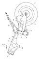
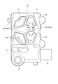
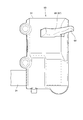
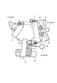
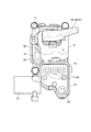
図3は、ハンドルスイッチの正面図である。図4は、ハンドルスイッチの背面図である。図5は、ハンドルスイッチの側面図である。図6は、ハンドルスイッチの内部構造を示す側面図である。図7は、ハンドルスイッチの内部構造を示す背面図である。図8は、自動二輪車の一部を示す斜視図である。
図3から図5に示すように、操舵ハンドル21には、ハンドルスイッチ50が取り付けられている。ハンドルスイッチ50は、操舵ハンドル21に取り付けられるスイッチケース51を備えている。
スイッチケース51の自動二輪車1の後方側の面には、操作スイッチとしてのメータ39の表示を操作するためのメータスイッチ59を備えており、メータスイッチ59は、それぞれ略十字状に配置された上スイッチ52、下スイッチ53、右スイッチ54、左スイッチ55をそれぞれ備えている。右スイッチ54および左スイッチ55は、1つのレバー状スイッチ56で構成されており、レバー状スイッチ56を右側に倒すと、右スイッチ54がONとなり、レバー状スイッチ56を左側に倒すと、左スイッチ55がONとなるように構成されている。
Next, the structure of the handle switch will be described in detail.
FIG. 3 is a front view of the handle switch. FIG. 4 is a rear view of the handle switch. FIG. 5 is a side view of the handle switch. FIG. 6 is a side view showing the internal structure of the handle switch. FIG. 7 is a rear view showing the internal structure of the handle switch. FIG. 8 is a perspective view showing a part of the motorcycle.
As shown in FIGS. 3 to 5, a
A meter switch 59 for operating the display of the
スイッチケース51の上方には、モードスイッチ57が配置されている。モードスイッチ57は、例えば、スタンダードモード、スポーツモードなどの走行モードの切り替えを行うことができるように構成されている。
スイッチケース51のモードスイッチ57の下方には、ホーンスイッチ58が配置されている。ホーンスイッチ58は、押動操作することにより、ホーン88(図9を参照)を鳴らすことができるように構成されている。
A
A
ホーンスイッチ58の下方には、ウインカスイッチ60のウインカレバー61が配置されている。ウインカレバー61を右側に倒すと、右ウインカスイッチ62がONとなり、右側のウインカ38が点滅する。ウインカレバー61を左側に倒すと、左ウインカスイッチ63がONとなり、左側のウインカ38が点滅するように構成されている。そして、ウインカレバー61が中央の位置でウインカキャンセルスイッチ64がONとなるように構成されている。
ウインカレバー61の下方には、ハザードスイッチ65が配置されている。ハザードスイッチ65は、押動操作することにより、両側のウインカ38が同時に点滅するように構成されている。
A
A
スイッチケース51の自動二輪車1の前方側の面には、ヘッドライト37のハイビームを点灯するディマースイッチ66およびヘッドライト37をパッシングするパッシングスイッチ67が配置されている。
本実施形態においては、ヘッドライト37のディマースイッチ66は、パッシングスイッチ67を兼ねており、ディマースイッチ66とパッシングスイッチ67とは、1つのレバースイッチ68で操作される。
On the front surface of the
In the present embodiment, the
図6および図7に示すように、スイッチケース51の内部には、スイッチ用基板保持部材が収容されている。スイッチ用基板保持部材は、本実施形態においては、第1スイッチ用基板保持部材71、第2スイッチ用基板保持部材72および第3スイッチ用基板保持部材73により構成されている。
第1スイッチ用基板保持部材71は、自動二輪車1の後方に指向するように配置されており、第1スイッチ用基板保持部材71には、第1スイッチ用基板74が取付けられている。第1スイッチ用基板74には、上スイッチ52、下スイッチ53、右スイッチ54、左スイッチ55、モードスイッチ57およびホーンスイッチ58の操作により、ONとされるスイッチ電極80がそれぞれ配置されている。
As shown in FIGS. 6 and 7, a switch substrate holding member is housed inside the
The
第2スイッチ用基板保持部材72は、第1スイッチ用基板保持部材71の下方に配置されており、第2スイッチ用基板保持部材72には、第2スイッチ用基板75が取付けられている。第2スイッチ用基板75には、ウインカスイッチ60、ウインカキャンセルスイッチ64およびハザードスイッチ65の操作により、ONとされるスイッチ電極80がそれぞれ配置されている。
第3スイッチ用基板保持部材73(図9を参照)は、自動二輪車1の前方に指向するように、第1スイッチ用基板保持部材71の反対側に配置されており、第3スイッチ用基板保持部材73には、第3スイッチ用基板76が取付けられている。第3スイッチ用基板76には、ヘッドライト37のハイとロートを切り替えるディマースイッチ66およびパッシングスイッチ67の操作により、ONとされるスイッチ電極80が配置されている。
The
The
図9は、本実施形態のハンドルスイッチ50の回路を示す回路図である。
図9に示すように、第1スイッチ用基板74、第2スイッチ用基板75および第3スイッチ用基板76には、それぞれスイッチ電極80が設けられており、これら各スイッチ電極80は、各基板74,75,76ごとに並列に接続されている。
各スイッチ電極80の一端には、信号線81が接続されており、スイッチ電極80の他端には、グランド線82が接続されている。信号線81とグランド線82との間には、それぞれ抵抗83およびコンデンサ84が接続されている。また、各スイッチ電極80の信号線81には、異なる抵抗値の抵抗85がそれぞれ接続されている。なお、1つの基板に2つのスイッチ電極80が配置されている場合には、一方のスイッチ電極80の信号線81にのみ抵抗85が接続されている。
このように本実施形態においては、スイッチ電極80は、抵抗分圧式のスイッチで構成されることになり、各操作スイッチを操作してスイッチ電極80をONにすることで、信号線81からは異なる電圧の電流が流れることになる。
FIG. 9 is a circuit diagram showing a circuit of the
As shown in FIG. 9,
A
As described above, in the present embodiment, the
また、第1スイッチ用基板74は、上スイッチ52、下スイッチ53、右スイッチ54、左スイッチ55が配置される回路と、モードスイッチ57およびホーンスイッチ58が配置される回路とにブロック分けされている。そのため、第1スイッチ用基板74からはブロック分けされた各回路からそれぞれ信号線81が引き出されることになる。
また、第2スイッチ用基板75および第3スイッチ用基板76からはそれぞれ1本ずつの信号線81が引き出される。
また、各基板のグランド線82は、それぞれ接続されて1本のグランド線82とされている。
このように構成することにより、第1スイッチ用基板74、第2スイッチ用基板75および第3スイッチ用基板76からは、4本の信号線81と1本のグランド線82がそれぞれ引き出されるように構成されている。
Further, the
Further, one
Further, the
With this configuration, four
各信号線81およびグランド線82は、それぞれコントロールユニット86に接続されるように構成されている。コントロールユニット86には、ヘッドライト37、ウインカ38、ホーン88などの電装部品がアナログ配線を介して接続されている。また、コントロールユニット86には、CAN通信線を介してメータ39およびECU87が接続されており、ECU87には、スロットルアクチュエータ89が接続されている。
コントロールユニット86は、各信号線81から出力されるアナログ信号をデジタル信号に変換するA/Dポート(図示せず)を備えている。
コントロールユニット86は、各信号線81から送られる信号の電圧値に基づいて、スイッチ電極80のうちいずれのスイッチ電極80がONにされたかを判定することができるように構成されている。そして、ONにされたスイッチ電極80に応じた電装部品の動作制御を行うように構成されている。
Each
The
The
図8に示すように、ヘッドパイプ15から後下方に延びる左右一対のメインフレーム16の間には、車体構成部品としてのエアクリーナーボックス31が配置されており、コントロールユニット86は、エアクリーナーボックス31の上方に支持されている。これにより、コントロールユニット86は、メインフレーム16よりも上方に位置するように構成されている。また、エアクリーナーボックス31の上方には、ECU87が支持されている。
各スイッチ電極80からの信号はアナログ信号であるため、コントロールユニット86との距離を近づけてノイズが入りにくいようにする必要があり、操舵ハンドル21を支持するヘッドパイプ15後方のメインフレーム16の上方にコントロールユニット86を配置することで、操舵ハンドル21の近傍にコントロールユニット86を配置することが可能となる。
エアクリーナーボックス31にコントロールユニット86を支持させるので、操舵ハンドル21近傍での取り付け自由度が高く、メインフレーム16に別途加工を必要としないでコントロールユニット86を支持することができる。
As shown in FIG. 8, an air
Since the signal from each
Since the
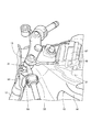
図10は、操舵ハンドル21に取付けられるブレーキレバー90を示す斜視図である。
図10に示すように、操舵ハンドル21に取付けられるレバー支持部材91を備えている。レバー支持部材91は、操舵ハンドル21を挟んで取り付けるため2分割構造とされており、レバー支持部材91の一端部には、操舵ハンドル21を挟む円形状の凹部92が設けられている。
レバー支持部材91の他端部には、ブレーキレバー90の端部が揺動自在に取り付けられている。レバー支持部材91のブレーキレバー90の近傍には、ブレーキスイッチ93が取り付けられている。
FIG. 10 is a perspective view showing a
As shown in FIG. 10, the
The end of the
ブレーキスイッチ93は、箱形のスイッチケース94と、スイッチケース94の側面に配置されたスイッチ95とを備えている。スイッチケース94は、レバー支持部材91の側面にスイッチ固定部材96により取り付けられる。スイッチ固定部材96は、略クランク状に形成されており、スイッチ固定部材96の一端部は、レバー支持部材91にねじ止めされている。
スイッチ固定部材96の他端部は、スイッチケース94の表面に当接し、このスイッチ固定部材96の他端部により、スイッチケース94をレバー支持部材91に固定するように構成されている。
ブレーキレバー90の端部には、スイッチ95を動作させるためのスイッチ動作部材97が取り付けられている。これにより、ブレーキレバー90を操作することにより、スイッチ動作部材97がスイッチ95をON・OFF動作させることができるように構成されている。
ブレーキスイッチ93には、配線ケーブル98が接続されており、スイッチ95のON・OFF動作による信号を出力するように構成されている。
The
The other end of the
A
A
次に、本実施形態の作用について説明する。
本実施形態において、例えば、ウインカレバー61を操作して、ウインカスイッチ60の左スイッチ55のスイッチ電極80をONにした場合に、コントロールユニット86は、信号線81から送られるアナログ信号をデジタル信号に変換し、信号線81の電圧値に基づいて、ウインカスイッチ60の左スイッチ55が操作されたことを判定し、左ウインカ38を動作させることができる。
同様に、メータ39の表示を操作するための上スイッチ52、下スイッチ53、右スイッチ54、左スイッチ55を操作することにより、コントロールユニット86を介してメータ39の表示を動作させることができる。
Next, the operation of this embodiment will be described.
In the present embodiment, for example, when the
Similarly, by operating the
また、ホーンスイッチ58を操作することにより、コントロールユニット86を介してホーン88を鳴らすことができる。ハザードスイッチ65を操作することにより、コントロールユニット86を介して両側のウインカ38が同時に点滅させることができる。ディマースイッチ66を操作することにより、コントロールユニット86を介してヘッドライト37のハイとローとを切り替えることができる。
また、モードスイッチ57を操作して、走行モードを切り替えることにより、コントロールユニット86を介して、スロットルアクチュエータ89の少なくとも燃料噴射量を変更することで、エンジン出力を走行モードに対応した出力に制御することができる。
Further, by operating the
Further, by operating the
以上述べたように、本実施形態においては、操作スイッチは、少なくともヘッドライト37のハイビームを点灯するディマースイッチ66と、ウインカスイッチ60と、ウインカキャンセルスイッチ64と、ハザードスイッチ65と、メータ39の表示を操作するメータスイッチ59とを備え、電装部品が接続されるコントロールユニット86を備え、自動二輪車1は、操舵ハンドル21を回転可能に支持するヘッドパイプ15から車体後方に延出するメインフレーム16を備え、コントロールユニット86は、操舵ハンドル21の近傍でメインフレーム16よりも上方に位置する。
これにより、配線を集約することができ、また、コントロールユニット86を備えることで、電装部品を適切に操作することができる。また、各スイッチからの信号はアナログであるため、各スイッチとコントロールユニット86との距離を近づけてノイズが入りにくいようにする必要があり、操舵ハンドル21を支持するヘッドパイプ後方のフレーム上方にコントロールユニット86を配置することで操舵ハンドル21近傍にコントロールユニット86を設けることができる。
As described above, in the present embodiment, the operation switches display at least the
As a result, the wiring can be integrated, and by providing the
また、本実施形態においては、メインフレーム16は、左右一対のフレームで構成され、左右一対のフレーム間に支持される車体構成部品を備え、コントロールユニット86は、エアクリーナーボックス31(車体構成部品)に支持される。
これにより、エアクリーナーボックス31(車体構成部品)に支持させるので、操舵ハンドル21近傍での取り付け自由度が高く、メインフレーム16に別途加工を必要としないでコントロールユニット86を支持することができる。
Further, in the present embodiment, the
As a result, since it is supported by the air cleaner box 31 (body component), the degree of freedom of mounting in the vicinity of the steering handle 21 is high, and the
また、本実施形態においては、メータスイッチ59は、上スイッチ52と、下スイッチ53と、右スイッチ54と、左スイッチ55とを備えている。
これにより、上スイッチ52と、下スイッチ53と、右スイッチ54と、左スイッチ55とからなるメータスイッチ59をハンドルスイッチ50に集約することができ、コンパクトにすることができる。
Further, in the present embodiment, the meter switch 59 includes an
As a result, the meter switch 59 including the
また、本実施形態においては、ヘッドライト37のディマースイッチ66は、ヘッドライト37をパッシングするパッシングスイッチ67を兼ねる。
これにより、ディマースイッチ66がパッシングスイッチ67を兼ねるので、スイッチを集約することができ、コンパクトにすることができる。
Further, in the present embodiment, the
As a result, since the
また、本実施形態においては、自動二輪車1は、スロットル操作に応じてスロットルバルブの開度を調整するスロットルアクチュエータ89を備え、少なくともスロットル操作に応じたスロットルバルブの開度を変更することで出力を設定し自動二輪車1の走行モードを変更するモードスイッチ57を備え、モードスイッチ57をハンドルスイッチ50に一体に設ける。
これにより、モードスイッチ57を他の操作スイッチとともに集約することができ、操作性を向上させることができる。
Further, in the present embodiment, the
As a result, the
また、本実施形態においては、自動二輪車1は、電装部品であるホーン88を備え、操作スイッチは、ホーンスイッチ58を備えている。
これにより、ホーンスイッチ58をハンドルスイッチ50に集約することができ、コンパクトにすることができる。
Further, in the present embodiment, the
As a result, the
また、本実施形態においては、ウインカスイッチ60とウインカキャンセルスイッチ64は一体のウインカレバー61で操作可能とし、ハザードスイッチ65は別体のスイッチで独立して操作可能とし、ウインカスイッチ60とウインカキャンセルスイッチ64とハザードスイッチ65は、1つの回路基板に搭載されている。
これにより、ウインカ38を操作するウインカスイッチ60とウインカキャンセルスイッチ64とを1つの回路基板に集約することができる。
Further, in the present embodiment, the winker switch 60 and the winker cancel
As a result, the winker switch 60 for operating the
また、本実施形態においては、上スイッチ52、下スイッチ53、右スイッチ54と、左スイッチ55は、1つの回路で構成され、モードスイッチ57とホーンスイッチ58は、1つの回路で構成され、これら2つの回路は、1つの回路基板74上に設けられる。
これにより、2つの回路を1つの回路基板74とすることでスペースを有効に活用することができる。
Further, in the present embodiment, the
As a result, the space can be effectively utilized by using the two circuits as one
なお、実施形態に基づいて本発明を説明したが、本発明は本実施形態に限定されるものではない。あくまでも本発明の一実施態様を例示するものであるから、本発明の趣旨を逸脱しない範囲で任意に変更、および応用が可能である。 Although the present invention has been described based on the embodiments, the present invention is not limited to the present embodiment. Since it merely illustrates one embodiment of the present invention, it can be arbitrarily modified and applied without departing from the spirit of the present invention.
1 自動二輪車
10 車体フレーム
15 ヘッドパイプ
16 メインフレーム
21 操舵ハンドル
31 エアクリーナーボックス
37 ヘッドライト
38 ウインカ
39 メータ
50 ハンドルスイッチ
51 スイッチケース
52 上スイッチ
53 下スイッチ
54 右スイッチ
55 左スイッチ
56 レバー状スイッチ
57 モードスイッチ
58 ホーンスイッチ
60 ウインカスイッチ
61 ウインカレバー
62 右ウインカスイッチ
63 左ウインカスイッチ
64 ウインカキャンセルスイッチ
65 ハザードスイッチ
66 ディマースイッチ
67 パッシングスイッチ
68 レバースイッチ
74 第1スイッチ用基板
75 第2スイッチ用基板
76 第3スイッチ用基板
80 スイッチ電極
81 信号線
82 グランド線
83 抵抗
84 コンデンサ
85 抵抗
86 コントロールユニット
89 スロットルアクチュエータ
1
Claims (8)
前記操作スイッチは、少なくともヘッドライト(37)のハイビームを点灯するディマースイッチ(66)と、ウインカスイッチ(60)と、ウインカキャンセルスイッチ(64)と、ハザードスイッチ(65)と、メータ(39)の表示を操作するメータスイッチ(59)とを備え、
前記電装部品が接続されるコントロールユニット(86)を備え、
前記自動二輪車(1)は、前記操舵ハンドル(21)を回転可能に支持するヘッドパイプ(15)から車体後方に延出するメインフレーム(16)を備え、前記コントロールユニット(86)は、前記操舵ハンドル(21)の近傍で前記メインフレーム(16)よりも上方に位置することを特徴とする自動二輪車のハンドルスイッチ。 A motorcycle (1) having a headlight (37), a winker (38), and a meter (39), which are electrical components of the motorcycle (1), and an operation switch for operating these electrical components on the steering handle 21. In the handle switch (50)
The operation switches are at least a dimmer switch (66) that lights a high beam of a headlight (37), a winker switch (60), a winker cancel switch (64), a hazard switch (65), and a meter (39). Equipped with a meter switch (59) to operate the display
A control unit (86) to which the electrical components are connected is provided.
The motorcycle (1) includes a main frame (16) extending rearward from a head pipe (15) that rotatably supports the steering handle (21), and the control unit (86) is the steering wheel. A motorcycle steering wheel switch characterized by being located near the steering wheel (21) and above the main frame (16).
Priority Applications (1)
| Application Number | Priority Date | Filing Date | Title |
|---|---|---|---|
| JP2020159329A JP7263299B2 (en) | 2020-09-24 | 2020-09-24 | motorcycle handlebar switch |
Applications Claiming Priority (1)
| Application Number | Priority Date | Filing Date | Title |
|---|---|---|---|
| JP2020159329A JP7263299B2 (en) | 2020-09-24 | 2020-09-24 | motorcycle handlebar switch |
Related Parent Applications (1)
| Application Number | Title | Priority Date | Filing Date |
|---|---|---|---|
| JP2018185684A Division JP2020055361A (en) | 2018-09-28 | 2018-09-28 | Motor cycle handlebar switch |
Publications (2)
| Publication Number | Publication Date |
|---|---|
| JP2020200036A true JP2020200036A (en) | 2020-12-17 |
| JP7263299B2 JP7263299B2 (en) | 2023-04-24 |
Family
ID=73744262
Family Applications (1)
| Application Number | Title | Priority Date | Filing Date |
|---|---|---|---|
| JP2020159329A Active JP7263299B2 (en) | 2020-09-24 | 2020-09-24 | motorcycle handlebar switch |
Country Status (1)
| Country | Link |
|---|---|
| JP (1) | JP7263299B2 (en) |
Citations (9)
| Publication number | Priority date | Publication date | Assignee | Title |
|---|---|---|---|---|
| JP2003331675A (en) * | 2002-05-16 | 2003-11-21 | Asahi Denso Co Ltd | Handle switch |
| JP2006096212A (en) * | 2004-09-30 | 2006-04-13 | Nippon Lock:Kk | Steering handle switch device for motorcycles |
| JP2007052989A (en) * | 2005-08-17 | 2007-03-01 | Asahi Denso Co Ltd | Dimmer switch |
| JP2010274899A (en) * | 2009-04-28 | 2010-12-09 | Honda Motor Co Ltd | Handle switch |
| JP2012046067A (en) * | 2010-08-26 | 2012-03-08 | Suzuki Motor Corp | Electric component mounting structure of motorcycle |
| WO2013001712A1 (en) * | 2011-06-30 | 2013-01-03 | 川崎重工業株式会社 | Saddle-type vehicle |
| JP2013028294A (en) * | 2011-07-29 | 2013-02-07 | Kawasaki Heavy Ind Ltd | Controller for vehicle, vehicle with controller, and control method thereof |
| JP2016130032A (en) * | 2015-01-13 | 2016-07-21 | ヤマハ発動機株式会社 | Headlamp device and saddle riding type vehicle |
| JP2018122831A (en) * | 2017-02-03 | 2018-08-09 | 朝日電装株式会社 | Handle switch |
-
2020
- 2020-09-24 JP JP2020159329A patent/JP7263299B2/en active Active
Patent Citations (9)
| Publication number | Priority date | Publication date | Assignee | Title |
|---|---|---|---|---|
| JP2003331675A (en) * | 2002-05-16 | 2003-11-21 | Asahi Denso Co Ltd | Handle switch |
| JP2006096212A (en) * | 2004-09-30 | 2006-04-13 | Nippon Lock:Kk | Steering handle switch device for motorcycles |
| JP2007052989A (en) * | 2005-08-17 | 2007-03-01 | Asahi Denso Co Ltd | Dimmer switch |
| JP2010274899A (en) * | 2009-04-28 | 2010-12-09 | Honda Motor Co Ltd | Handle switch |
| JP2012046067A (en) * | 2010-08-26 | 2012-03-08 | Suzuki Motor Corp | Electric component mounting structure of motorcycle |
| WO2013001712A1 (en) * | 2011-06-30 | 2013-01-03 | 川崎重工業株式会社 | Saddle-type vehicle |
| JP2013028294A (en) * | 2011-07-29 | 2013-02-07 | Kawasaki Heavy Ind Ltd | Controller for vehicle, vehicle with controller, and control method thereof |
| JP2016130032A (en) * | 2015-01-13 | 2016-07-21 | ヤマハ発動機株式会社 | Headlamp device and saddle riding type vehicle |
| JP2018122831A (en) * | 2017-02-03 | 2018-08-09 | 朝日電装株式会社 | Handle switch |
Also Published As
| Publication number | Publication date |
|---|---|
| JP7263299B2 (en) | 2023-04-24 |
Similar Documents
| Publication | Publication Date | Title |
|---|---|---|
| JP4083402B2 (en) | Motorcycle taillight structure | |
| CN102530138B (en) | Light apparatus for motorbike | |
| JP2016078497A (en) | Saddle riding type vehicle | |
| JP6333873B2 (en) | Air cleaner structure for saddle-ride type vehicles | |
| JP4151773B2 (en) | Front fork structure in saddle riding type vehicle | |
| JP4145562B2 (en) | One-lamp headlight device for motorcycles | |
| WO2020022377A1 (en) | Straddle-type vehicle | |
| CA2648828C (en) | Headlight support structure for saddle-riding type vehicle | |
| JP5748530B2 (en) | Position light, headlight structure and cowl structure for saddle riding type vehicles | |
| CN110979521B (en) | Handle switch of automatic two-wheeler | |
| JP7263299B2 (en) | motorcycle handlebar switch | |
| JPWO2003035456A1 (en) | Headlamp support structure for motorcycles | |
| CN106364603A (en) | Straddling type vehicle | |
| JP3562630B2 (en) | Vehicle turn signal light | |
| CN103707962B (en) | Illuminator device in Straddle-type vehicle | |
| JP2013035305A (en) | Motorcycle | |
| CN1042310C (en) | Small motorcycle front body structure | |
| JP2021084483A (en) | Saddle-riding type vehicle | |
| JP7212089B2 (en) | Straddle-type vehicle handle cover structure | |
| WO2019049467A1 (en) | Saddle-type-vehicle front structure | |
| JP2020066408A (en) | Saddle-riding type vehicle | |
| CN104554525B (en) | Saddle-riding type vehicle | |
| JP7610698B2 (en) | Saddle-type vehicle | |
| JP2021030798A (en) | Saddle-riding type vehicle | |
| JP3248110B2 (en) | Handle cover device for small vehicles |
Legal Events
| Date | Code | Title | Description |
|---|---|---|---|
| A621 | Written request for application examination |
Free format text: JAPANESE INTERMEDIATE CODE: A621 Effective date: 20210803 |
|
| A131 | Notification of reasons for refusal |
Free format text: JAPANESE INTERMEDIATE CODE: A131 Effective date: 20220405 |
|
| A521 | Request for written amendment filed |
Free format text: JAPANESE INTERMEDIATE CODE: A523 Effective date: 20220602 |
|
| A131 | Notification of reasons for refusal |
Free format text: JAPANESE INTERMEDIATE CODE: A131 Effective date: 20221018 |
|
| A521 | Request for written amendment filed |
Free format text: JAPANESE INTERMEDIATE CODE: A523 Effective date: 20221219 |
|
| TRDD | Decision of grant or rejection written | ||
| A01 | Written decision to grant a patent or to grant a registration (utility model) |
Free format text: JAPANESE INTERMEDIATE CODE: A01 Effective date: 20230328 |
|
| A61 | First payment of annual fees (during grant procedure) |
Free format text: JAPANESE INTERMEDIATE CODE: A61 Effective date: 20230412 |
|
| R150 | Certificate of patent or registration of utility model |
Ref document number: 7263299 Country of ref document: JP Free format text: JAPANESE INTERMEDIATE CODE: R150 |