JP2020200057A - Sheet storage container - Google Patents
Sheet storage container Download PDFInfo
- Publication number
- JP2020200057A JP2020200057A JP2019106864A JP2019106864A JP2020200057A JP 2020200057 A JP2020200057 A JP 2020200057A JP 2019106864 A JP2019106864 A JP 2019106864A JP 2019106864 A JP2019106864 A JP 2019106864A JP 2020200057 A JP2020200057 A JP 2020200057A
- Authority
- JP
- Japan
- Prior art keywords
- sheet
- container body
- roll
- container
- take
- Prior art date
- Legal status (The legal status is an assumption and is not a legal conclusion. Google has not performed a legal analysis and makes no representation as to the accuracy of the status listed.)
- Granted
Links
Images
Landscapes
- Containers And Packaging Bodies Having A Special Means To Remove Contents (AREA)
- Details Of Rigid Or Semi-Rigid Containers (AREA)
Abstract
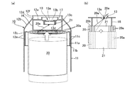
【課題】シートが引き出されて軽くなった場合でも、ロール状シートが容器本体の内部で動き易くなるのを抑制し、シートを容器の外にスムーズに取り出すことを可能にするシート収納容器を提供する。【解決手段】シート20aを巻回してなるロール状シート20が収納される容器本体11と、容器本体11の上端開口を覆って容器本体11に着脱可能に装着され、シート11aを取り出すための取出部13を有する蓋体12とを含んで構成されるシート収納容器10である。取出部13には、シート止めスリット13aが形成されており、蓋体12には、内側から容器本体11側に突出して、ロール状シート20の上端面20bを当接可能な環状当接リブ16が、取出部13の外周部分を囲んで設けられている。シート止めスリット13aが形成された取出部13は、その中心位置C1を、容器本体11の中心位置C2から偏心させた状態で設けられている。【選択図】図2PROBLEM TO BE SOLVED: To provide a sheet storage container which suppresses the roll-shaped sheet from becoming easy to move inside a container body and enables the sheet to be smoothly taken out of the container even when the sheet is pulled out and becomes lighter. do. SOLUTION: A container main body 11 in which a roll-shaped sheet 20 formed by winding a sheet 20a is housed, and a container main body 11 that covers the upper end opening of the container main body 11 and is detachably attached to the container main body 11 and taken out for taking out the sheet 11a. A sheet storage container 10 including a lid 12 having a portion 13. A sheet retaining slit 13a is formed in the take-out portion 13, and an annular contact rib 16 that projects from the inside toward the container body 11 and can abut the upper end surface 20b of the roll-shaped sheet 20 on the lid body 12. However, it is provided so as to surround the outer peripheral portion of the take-out portion 13. The take-out portion 13 in which the sheet stop slit 13a is formed is provided in a state where the center position C1 thereof is eccentric from the center position C2 of the container body 11. [Selection diagram] Fig. 2
Description
本発明は、シート収納容器に関し、特に、ロール状シートが収納される容器本体と、シートを取り出すための取出部を有する蓋体とを含んで構成されるシート収納容器に関する。 The present invention relates to a sheet storage container, and more particularly to a sheet storage container including a container body for storing a roll-shaped sheet and a lid having a take-out portion for taking out the sheet.
例えばウェットシート等のシートをロール状に巻回してなるロール状シートが収納されるシート収納容器として、有底円筒形状の容器本体と、容器本体の上端開口を覆って容器本体に着脱可能に装着される、蓋体とからなる容器が知られている(例えば、特許文献1参照)。このようなシート収納容器では、蓋体に、公知のシート止めスリットが形成された取出部が設けられている。シートは、帯状に連続して延設する当該シートを巻回して形成された、円柱形状のロール状シートの中央の中空芯部において、最内側層のシートから順次引き剥がされるようにして、蓋体側に連続して引き出されると共に、取出部に形成されたシート止めスリットを介して容器の外に取り出され、当該シートに設けられたミシン目等の部分で切り離されて、端部をシート止めスリットに保持させた状態で、一枚一枚の単位シートとして用いられることになる。 For example, as a sheet storage container for storing a roll-shaped sheet obtained by winding a sheet such as a wet sheet in a roll shape, the container body has a bottomed cylindrical shape and is detachably attached to the container body by covering the upper end opening of the container body. A container made of a lid is known (see, for example, Patent Document 1). In such a sheet storage container, the lid is provided with a take-out portion in which a known sheet retaining slit is formed. The sheet is a lid formed by winding the sheet that is continuously extended in a strip shape so as to be sequentially peeled off from the innermost layer sheet at the central hollow core portion of the cylindrical roll-shaped sheet. Along with being continuously pulled out to the body side, it is taken out of the container through a sheet fixing slit formed in the take-out part, separated at a part such as a perforation provided on the sheet, and the end portion is a sheet fixing slit. It will be used as a unit sheet one by one in the state of being held in the air.
従来のシート収納容器では、ロール状シートからシートを引き出し始めた初期の段階では、ロール状シートが相当の重量を保持しているので、中央の中空芯部において最内側層のシートから順次連続して引き剥がす際の抵抗力をロール状シートによって安定して支持して、スムーズに蓋体側に引き出すことが可能であるが、例えばある程度の量のシートが引き出されて、ロール状シートが軽くなったり中空芯部の内径が大きくなったりすると、最内側層のシートを引き剥がす際の抵抗力を安定して支持することが難しくなって、ロール状シートが容器本体の内部で動き易くなると共に、中空芯部から、例えば複数層に重ね合わされたままの状態で内側層のシートがまとめて引き出されることにより、シート止めスリットの部分で詰まり易くなって、シートを容器の外にスムーズに取り出すことが困難になる場合がある。 In the conventional sheet storage container, since the roll-shaped sheet holds a considerable weight at the initial stage when the sheet is pulled out from the roll-shaped sheet, the roll-shaped sheet is sequentially continuous from the innermost layer sheet in the central hollow core portion. It is possible to stably support the resistance force when peeling off with the roll-shaped sheet and pull it out smoothly to the lid side, but for example, a certain amount of sheet is pulled out and the roll-shaped sheet becomes lighter. If the inner diameter of the hollow core becomes large, it becomes difficult to stably support the resistance force when the innermost layer sheet is peeled off, and the roll-shaped sheet becomes easier to move inside the container body and is hollow. By pulling out the inner layer sheets together from the core, for example, in a state where they are stacked in multiple layers, it becomes easy for the sheets to be clogged at the sheet retaining slits, and it is difficult to smoothly remove the sheets from the container. May become.
本発明は、容器本体に収容されたロール状シートからある程度の量のシートが引き出されて、ロール状シートか軽くなった場合でも、ロール状シートが容器本体の内部で動き易くなるのを効果的に抑制すると共に、中空芯部から、内側層のシートが複数層に重ね合わされたままの状態でまとめて引き出されるのを回避して、シートを容器の外にスムーズに取り出すことのできるシート収納容器を提供することを目的とする。 The present invention is effective in making the roll-shaped sheet easier to move inside the container body even when a certain amount of the sheet is pulled out from the roll-shaped sheet housed in the container body and the roll-shaped sheet becomes lighter. A sheet storage container that allows the sheets to be smoothly taken out of the container by avoiding pulling out the inner layer sheets from the hollow core in a state where they are stacked in multiple layers. The purpose is to provide.
本発明は、シートをロール状に巻回してなるロール状シートが収納される有底筒形状の容器本体と、該容器本体の上端開口を覆って該容器本体に着脱可能に装着され、上面部にシートを取り出すための取出部を有する蓋体とを含んで構成されるシート収納容器であって、前記蓋体の前記取出部には、シート止めスリットが形成されており、前記蓋体には、内側から前記容器本体側に突出して、前記ロール状シートの上端面を当接させることが可能な環状当接リブが、前記取出部の外周部分を囲んで設けられており、前記シート止めスリットが形成された前記取出部は、その中心位置を、前記容器本体の中心位置から偏心させた状態で設けられているシート収納容器を提供することにより、上記目的を達成したものである。 INDUSTRIAL APPLICABILITY The present invention covers a bottomed tubular container body in which a roll-shaped sheet formed by winding a sheet in a roll shape is stored, and a container body that covers the upper end opening of the container body and is detachably attached to the container body. A sheet storage container including a lid having a take-out portion for taking out a sheet, wherein a sheet stop slit is formed in the take-out portion of the lid, and the lid has a take-out portion. An annular contact rib that protrudes from the inside toward the container body and is capable of contacting the upper end surface of the roll-shaped sheet is provided so as to surround the outer peripheral portion of the take-out portion, and the sheet stop slit. The take-out portion formed with the above-mentioned object has achieved the above object by providing a sheet storage container provided in a state where the center position thereof is eccentric from the center position of the container body.
本発明のシート収納容器によれば、容器本体に収容されたロール状シートからある程度の量のシートが引き出されて、ロール状シートか軽くなった場合でも、ロール状シートが容器本体の内部で動き易くなるのを効果的に抑制して、シートを容器の外にスムーズに取り出すことができる。 According to the sheet storage container of the present invention, even if a certain amount of sheet is pulled out from the roll-shaped sheet housed in the container body and the roll-shaped sheet becomes lighter, the roll-shaped sheet moves inside the container body. The sheet can be smoothly taken out of the container by effectively suppressing the tendency.
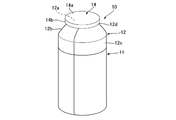
図1及び図2に示す本発明の好ましい一実施形態に係るシート収納容器10は、例えば不織布からなるシートが、洗浄液等の液体成分を含侵した状態でロール状に巻回されているロール状シート20を、容器本体11に収容している。シート収納容器10は、蓋体12に設けられた取出部13(図2参照)を介して、収容したロール状シート20からシート(ウェットシート20a)を容器の外に連続して取り出すことを可能にすると共に(図4(a)、(b)参照)、取り出したウェットシート20aを、例えば予め設けられているミシン目等で切り離して、一枚一枚の単位シートとして使用できるようにする容器として用いられる。洗浄液としては、水、抗菌成分、界面活性剤等が含まれている。本実施形態のシート収納容器10は、ある程度の量のウェットシート20aが使用されて、ロール状シート20が軽くなった場合でも(図5(a)、(b)参照)、ロール状シート20が容器本体11の内部で動き易くなるのを抑制すると共に、ロール状シート20の中央の中空芯部21から、内側層のウェットシート20aが複数層に重ね合わされたままの状態でまとめて引き出されるのを回避して、ウェットシート20aを収納容器10の外にスムーズに取り出すことができるようにする機能を備えている。
The
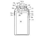
そして、本実施形態のシート収納容器10は、図1及び図2に示すように、シートとして、好ましくはウェットシート20aをロール状に巻回してなるロール状シート20が収納される有底筒形状の容器本体11と、容器本体11の上端開口を覆って容器本体11に着脱可能に装着され、上面部12aにウェットシート11aを取り出すための取出部13を有する蓋体12とを含んで構成される容器である。蓋体12の取出部13には、シート止めスリット13aが形成されており、蓋体12には、内側から容器本体11側に突出して、ロール状シート20の上端面20bを当接させることが可能な環状当接リブ16が、取出部13の外周部分を囲んで設けられている。シート止めスリット13aが形成された取出部13は、その中心位置C1を、容器本体11の中心位置C2から偏心させた状態で設けられている。
Then, as shown in FIGS. 1 and 2, the
また、本実施形態では、シート収納容器10は、好ましくは、容器本体11が有底円筒形状を備えており、環状当接リブ14は円環形状を備えている。
Further, in the present embodiment, in the
本実施形態では、ロール状シート20を形成するウェットシート20aは、延設方向と垂直な横幅が例えば100〜170mm程度(本実施形態では、135mm)の、帯状に連続して延設するシートとなっており、ロール状に巻回されることによってロール状シート20が形成される。ロール状シート20は、例えば直径が50〜100mm程度(本実施形態では、70mm)、高さが100〜170mm程度(本実施形態では、135mm)の、容器本体11に収容可能な大きさの円柱形状を有している。ロール状シート20の高さは、ウェットシート20aの横幅に相当する。円柱形状のロール状シート20は、これの中央部分に、両側の端面の間を貫通するようにして中空芯部21(図4(a)、図5(a)参照)を残置した状態で、ロール状に巻回されている。この中空芯部21を介して、ウェットシート20aを、最内側層のものから順次引き剥がして、蓋体12側に連続して引き出すことができるようになっている。帯状に連続して延設するウェットシート20aには、延設方向において例えば110〜180mm程度(本実施形態では、150mm)の所定の間隔毎に、ミシン目等による切り離し案内線(図示せず)が、横幅方向を横断して形成されている。ロール状シート20の中空芯部21から引き出されたウェットシート20aは、取出部13に形成されたシート止めスリット13aを介して収納容器10の外に取り出され、ミシン目等による切り離し案内線よりも容器本体11側の部分をシート止めスリット13aに保持させた状態で、ミシン目等による切り離し案内線の部分で切り離されて、例えば110〜180mm程度(本実施形態では、150mm)の長さを有する一枚一枚の単位シートとして用いられることになる。
In the present embodiment, the
ロール状シート20を収容する容器本体11は、例えばポリエチレン、ポリプロピレン等のポリオレフィンやポリエチレンテレフタレート等のポリエステル等を用いたブロー成形品となっている。容器本体11は、図1及び図2に示すように、好ましくは外径が60〜150mm程度(本実施形態では、97mm)の大きさの有底の円筒形状を備えており、また例えば110〜200mm程度(本実施形態では、160mm)の高さを有している。容器本体11は、上端部に、段部11bを介して僅かに縮径した装着筒部11aを備えており、この装着筒部11aの外周面には、後述する蓋体12を着脱可能に螺着させるための雄ネジ凸条11cが設けられている。装着筒部11aの上端開口は、容器本体11の内部にロール状シート20を収納させるための収納口となっている。シート収納容器10の流通、販売時や、使用前の状態では、容器本体11に収納されたロール状シート20から、ウェットシート20aに含侵した液体成分を揮散させないように、装着筒部11aの上端開口は、アルミ箔等(図示せず)で覆って閉塞しておくことができる。例えば消費者は、蓋体12を容器本体11から一旦取り外した後に、装着筒部11aの上端開口からアルミ箔等を除去し、ロール状シート20から引き出したウェットシート20aの端部を、取出部13のシート止めスリット13aを介して取出部13の外側に臨ませて、蓋体12を容器本体11に再び装着することにより、ウェットシート20aを容器の外に取り出して使用可能な状態とすることができる。
The
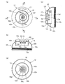
容器本体11に着脱可能に一体として装着される蓋体12は、例えばポリエチレン、ポリプロピレン等のポリオレフィンやポリエチレンテレフタレート等のポリエステル等を用いた射出成形品となっている。蓋体12は、図3(a)〜(d)にも示すように、容器本体11の装着筒部11aに装着される装着スリーブ部12cと、縮径部12bと、上面部12aとを含んで構成される。装着スリーブ部12cは、容器本体11の外径と同様の外径を有する円環帯状の部分であり、縮径部12bは、装着スリーブ部12cの上端部から上方の上面部12aに向けて滑らかに縮径する部分である。縮径部12bの上端部分の上面部12aとの接続部分には、上端を頂部とする三角形の断面形状を備える周壁部12dが、上面部12aの略全周に亘って連続して設けられている。本実施形態では、周壁部12dの上端部に、蓋体12の取出部13を覆う上蓋14が、着脱可能に装着される(図1、図2参照)。
The
装着スリーブ部12cは、容器本体11の装着筒部11aに螺着される部分であって、容器本体11の胴部の外径と同様の外径を有すると共に、装着筒部11aと同様の高さを有している。装着スリーブ部12cの内周面には、雌ネジ凸条12eが設けられている。この雌ネジ凸条12eを、容器本体11の装着筒部11aの雄ネジ凸条11cに螺合することによって、蓋体12を、容器本体11に着脱可能に一体として装着することができる。
The mounting
縮径部12bは、装着スリーブ部12cの上端部から上方の上面部12aに向けて滑らかに縮径する部分となっている。縮径部12bが設けられていることにより、シート収納容器10の全体の意匠性を向上させている。
The reduced
周壁部12dは、上面部12aの周囲を囲むようにして、円環形状に延設する部分となっており、縮径部12bの上端部に連なる斜辺部と、上面部12aの周縁部から立設する立設部とからなる、三角形の断面形状を有している(図3(c)参照)。周壁部12dの上端部には、上蓋14の係合リブ14c(図2参照)を係合させるための係合凸部12fが設けられている。
The
上蓋14は、図1及び図2に示すように、周壁部12dの上端部の外側に嵌め込むようにして装着可能な、周壁部12dの外径と同様の内径を備える円形状の部分となっている。上蓋14は、円形の天面部14aと天面部14aの周縁部から下方に突出して設けられた装着スカート部14bとからなる。装着スカート部14bの内側面から環状に突出して、係合リブ14cが設けられている。上蓋14は、装着スカート部14bを弾性変形させつつ周壁部12dの上端部に上方から押し込むようにして、係合リブ14cを周壁部12dの上端部の係合凸部12fに係合させることにより、蓋体12の取出部13を覆って着脱可能に取り付けることができる。
As shown in FIGS. 1 and 2, the
また、上蓋14には、下面側から突出して、同心状に2重に配置された、内側係止リング14d及び外側係止リング14eが設けられている。取出部13を覆って上蓋14が装着された際に、これらの内側係止リング14d及び外側係止リング14eが、蓋体12の上面部12aから外側に突出して取出部13の外周部分を囲んで環状に設けられた、封止リング17の上端部に、当該上端部を挟み込むようにして係止される。これによって、シート収納容器10の非使用時に、取出部13の上方空間を封止して、ウェットシート20aやロール状シート20に含侵した液体成分が揮散するのを、効果的に回避することが可能になる。
Further, the
そして、本実施形態では、図3(a)〜(d)に示すように、好ましくは周壁部12dによって周囲を囲まれる蓋体12の上面部12aには、ウェットシート11aを取り出すための、シート止めスリット13aが形成された取出部13が設けられている。また蓋体12の好ましくは上面部12aの内側から容器本体11側に突出して、ロール状シート20の上端面20bを当接させることが可能な環状当接リブ16が、取出部13の外周部分を囲んで設けられている。環状当接リブ16は、蓋体12の縮径部12bの内側から容器本体11側に突出して設けることもできる。
Then, in the present embodiment, as shown in FIGS. 3A to 3D, a sheet for taking out the
取出部13は、その中心位置C1を、容器本体11の中心位置C2から偏心させた状態で設けられた、取出開口13bを含んで構成されている。本実施形態では、取出部13の中心位置C1は、容器本体11の中心位置C2から偏心させた状態で設けられている。上面部12aの内側には、取出開口13bの周囲を囲うようにして当該取出開口13bと同心状に配置された、環状のスリット部材係止リブ13cが、容器本体11側に突出して設けられている。このスリット部材係止リブ13cに嵌め込むようにして、公知の例えばエラストマー材料からなるスリット形成部材13dが装着固定されることによって、シート止めスリット13aが取出部13に形成される。
The take-out
環状当接リブ16は、好ましくは円環形状を備えるリブとなっており、好ましくは容器本体11に収納される円柱形状のロール状シート20の直径よりも小さく、且つロール状シート20の直径の1/2よりも大きな外径を有するように形成される。これによって環状当接リブ16は、好ましくは容器本体11の中心位置から、ロール状シート20の半径の1/2以上、径方向に離れた領域に設けることが可能になる。環状当接リブ16が、容器本体11の中心位置から、ロール状シート20の半径の1/2以上、径方向に離れた領域に設けられることにより、未使用時の状態からロール状シート20が消費されることで中空芯部21が大きくなった場合でも、確実に環状当接リブ16の下端にロール状シート20の上端面20bを接触(当接)させることが可能になる。
The
また、環状当接リブ16は、容器本体11及び蓋体12と同心状に配置されて設けられていることが好ましい。環状当接リブ16が、容器本体11及び蓋体12と同心状に配置されて設けられていることにより、ロール状シート20の上端面20bを環状当接リブ16の下端に全周に亘って接触させ易くすることが可能になる。
Further, it is preferable that the
さらに、環状当接リブ16は、蓋体12が容器本体11に装着された状態で(図2参照)、容器本体11の装着筒部11aによる上端開口を超えない高さで、蓋体12の上面部12aの内側から容器本体11側に突出して設けられていることが好ましい。これによって、シート収納容器10の流通、販売時や、使用前に、ロール状シート20のウェットシート20aに含侵した液体成分の揮散を防止するために取り付けられた、装着筒部11aの上端開口を覆うアルミ箔等を傷付けることなく、蓋体12を容器本体11に装着することが可能になる。容器本体11の装着筒部11aによる上端開口と、環状当接リブ16の下端部との間の隙間は、2〜10mmに保持しておくことが好ましい。環状当接リブ16の厚さは、ロール状シート20を形成するウェットシート20aの厚さよりも大きくなっていることが好ましく、例えば1mm程度となっていることが好ましい。環状当接リブ16の下端の位置は、全周に亘って同じ高さ位置となっていることが好ましい。これによって、ロール状シート20の上端面20bを安定した状態で支持して、ロール状シート20が持ち上ろうとするのを押えることが可能になる。また、環状当接リブ16の下端が容器本体11の装着筒部11aによる上端開口まで届いていないことで、中空芯部21から引き出したウェットシート20aを、取出開口13bに至るまで、環状当接リブ16に接触し難くすることが可能になる。これによって、引き出し途中のウェットシート20aが、環状当接リブ16との接触抵抗によって、意図せずにミシン目等による切り離し案内線の部分で切り離されるのを、効果的に回避することが可能になる。
Further, the
そして、本実施形態では、蓋体12の上面部12aのシート止めスリット13aが形成された取出部13は、その中心位置C1を、容器本体11の中心位置C2から偏心させた状態で設けられている。取出部13が、その中心位置C1を、容器本体11中心位置C2から偏心させた状態で設けられていることにより、後述するように、中空芯部21において内層側のウェットシート20aに全面で張り付いているシートを、シートの上部に張り付いている端部から順次内側方向に引き剥がすようにしながら、斜めに引っ張り出すことが可能になって、ウェットシート20aをスムーズに取り出すことが可能になる。このような観点から、取出部13は、その中心位置C1を、容器本体11の中心位置C2から、環状当接リブ16の内径の3〜25%の偏心量で偏心させた状態で設けられていることが好ましく、環状当接リブ16の内径の3〜15%の偏心量で偏心させた状態で設けられていることがより好ましく、環状当接リブ16の内径の5〜10%の偏心量で偏心させた状態で設けられていることがさらに好ましい。
Then, in the present embodiment, the take-out
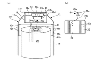
本実施形態のシート収納容器10では、上述のように、例えば消費者は、蓋体12を容器本体11から一旦取り外した後に、装着筒部11aの上端開口からアルミ箔等を除去し、ロール状シート20から引き出したウェットシート20aの端部を、取出部13のシート止めスリット13aを介して取出部13の外側に臨ませて、蓋体12を容器本体11に再び装着することにより、ウェットシート20aを容器の外に取り出して使用可能な状態とする。しかる後に、図4(a)、(b)に示すように、消費者は、取出部13の外側に臨むウェットシート20aの端部を手で持って、ウェットシート20aを引き出せば、ウェットシート20aは、容器本体11に収容されたロール状シート20の中央の中空芯部21から、最内層のシートが順次引き剥がされるようにして引き出されて、収納容器10の外に連続して取り出される。取り出されたウェットシート20aは、ミシン目等による切り離し案内線の部分で切り離されて、端部をシート止めスリット13aに保持させた状態で、一枚一枚の単位シートとして用いることができる。
In the
本実施形態のシート収納容器10では、ロール状シート20からウェットシート20aを引き出し始めた初期の段階では、ロール状シート20が相当の重量を保持しているので、中央の中空芯部21において最内側層のウェットシート20aから順次連続して引き剥がす際の抵抗力を、ロール状シート20によって安定して支持して、スムーズに蓋体12側に引き出すことが可能である。また、ウェットシート20aを引き出し始めた初期の段階でも、取出部13が、その中心位置C1を、容器本体11の中心位置C2から偏心させた状態で設けられているので、中央の中空芯部21において最内側層のウェットシート20aを、より引き剥がし易くして、内側層のウェットシート20aが複数層に重ね合わされたままの状態でまとめて引き出されるのを、効果的に回避することが可能になる。
In the
一方、図5(a)、(b)に示すように、例えばある程度の量のウェットシート20aが引き出されて、ロール状シート20が軽くなったり中空芯部21の内径が大きくなったりすると、最内側層のウェットシート20aを引き剥がす際の抵抗力を安定して支持することが難しくなって、ロール状シート20が容器本体11の内部で持ち上がったりするなど動き易くなると共に、中空芯部21から、例えば複数層に重ね合わされたままの状態で内側層のウェットシート20aがまとめて引き出されることにより、シート止めスリット13aの部分で詰まり易くなって、ウェットシート20aを収納容器10の外にスムーズに取り出すことが困難になる場合がある。
On the other hand, as shown in FIGS. 5A and 5B, for example, when a certain amount of the
本実施形態のシート収納容器10によれば、このように容器本体11に収容されたロール状シート20か軽くなった場合でも、ロール状シート20が容器本体11の内部で動き易くなるのを効果的に抑制すると共に、中空芯部21から、内側層のウェットシート20aが複数層に重ね合わされたままの状態でまとめて引き出されるのを回避して、ウェットシート20aを容器の外にスムーズに取り出すことが可能なる。
According to the
すなわち、本実施形態のシート収納容器10によれば、蓋体12には、上面部12aの内側から容器本体11側に突出して、ロール状シート20の上端面20bを当接させることが可能な環状当接リブ16が、取出部13の外周部分を囲んで設けられており、シート止めスリット13aが形成された蓋体12の取出部13は、その中心位置C1を、容器本体11の中心位置C2から偏心させた状態で設けられている。
That is, according to the
これらによって、本実施形態によれば、ロール状シート20が軽くなることで、中空芯部21で最内側層のウェットシート20aを引き剥がす際の引き出し力によって、例えばロール状シート20が引き上げられるようにして上方に移動しようとしても、環状当接リブ16の下端部が、例えばロール状シート20における、ウェットシート20aが取り出される中央の中空芯部21から離れた外周領域において、ロール状シート20の上端面に好ましくは環状に連続して当接することにより、ロール状シート20が容器本体11の内部で動き易くなるのを効果的に抑制することが可能になる。また、取出部13は、その中心位置C1を、容器本体11の中心位置C2から偏心させた状態で設けられているので、環状当接リブ16に当接させることによってロール状シート20の動きを抑制したこととの相乗効果により、中空芯部21において内層側のウェットシート20aに全面で張り付いているシートを、シートの上部に張り付いている端部から順次内側方向に引き剥がすようにしながら、斜めに引っ張り出すことが可能になって、ウェットシート20aをスムーズに取り出すことが可能になる。
As a result, according to the present embodiment, the roll-shaped
なお、本発明は、上記の実施形態に限定されることなく、種々の変更が可能である。例えば、容器本体は、有底円筒形状を備えている必要は必ずしもなく、楕円断面形状や、その他の断面形状を有する有底筒形状を備えていても良い。環状当接リブは、円環形状を備えている必要は必ずしもなく、楕円断面形状や矩形断面形状等、その他の断面形状を有する環形状を備えていても良い。ロール状シートが軽くなって上方に移動した際に、環状当接リブの下端部は、ロール状シートの上端面において環状に連続して当接する必要は必ずしも無く、上方への移動の仕方によっては、例えばロール状シートが斜めに傾きながら持ち上がることで、その一部のみが当接するようになっていても良い。環状当接リブは、容器本体及び蓋体と同心状に配置されている必要は必ずしも無く、偏心した状態で配置されていても良い。収納されるロール状シートは、液体成分を含侵させたウェットシートを巻回したものである必要は必ずしも無く、液体成分を含侵してないシートや、その他の種々のシート材料をロール状に巻回して形成することもできる。また、蓋体の取出部を覆う上蓋は、上述のようなかぶせ蓋によるものの他、蓋体にネジ嵌合される蓋や、蓋体に対して回転可能にヒンジ連結された蓋等の、公知の種々の蓋を用いることができる。 The present invention is not limited to the above embodiment, and various modifications can be made. For example, the container body does not necessarily have to have a bottomed cylindrical shape, and may have a bottomed cylindrical shape having an elliptical cross-sectional shape or another cross-sectional shape. The annular contact rib does not necessarily have to have an annular shape, and may have a ring shape having another cross-sectional shape such as an elliptical cross-sectional shape or a rectangular cross-sectional shape. When the roll-shaped sheet becomes lighter and moves upward, the lower end of the annular contact rib does not necessarily have to continuously contact the upper end surface of the roll-shaped sheet in an annular shape, and depending on how it is moved upward. For example, when the roll-shaped sheet is lifted while tilting diagonally, only a part of the roll-shaped sheet may come into contact with the sheet. The annular contact ribs do not necessarily have to be arranged concentrically with the container body and the lid, and may be arranged in an eccentric state. The rolled sheet to be stored does not necessarily have to be a wound wet sheet impregnated with a liquid component, and a sheet not impregnated with a liquid component or various other sheet materials are wound in a roll shape. It can also be formed by turning. Further, the upper lid that covers the take-out portion of the lid is known as a lid that is screw-fitted to the lid, a lid that is rotatably hinged to the lid, and the like, in addition to the lid as described above. Various lids can be used.
10 シート収納容器
11 容器本体
11a 装着筒部
11b 段部
12 蓋体
12a 上面部
12b 縮径部
12c 装着スリーブ部
12d 周壁部
13 取出部
13a シート止めスリット
13b 取出開口
13c スリット部材係止リブ
13d スリット形成部材
14 上蓋
16 環状当接リブ
17 封止リング
20 ロール状シート
20a ウェットシート(シート)
21 中空芯部
C1 取出部の中心位置
C2 容器本体の中心位置
10
21 Hollow core part C1 Center position of take-out part C2 Center position of container body
Claims (6)
前記蓋体の前記取出部には、シート止めスリットが形成されており、前記蓋体には、内側から前記容器本体側に突出して、前記ロール状シートの上端面を当接させることが可能な環状当接リブが、前記取出部の外周部分を囲んで設けられており、
前記シート止めスリットが形成された前記取出部は、その中心位置を、前記容器本体の中心位置から偏心させた状態で設けられているシート収納容器。 A bottomed cylinder-shaped container body in which a roll-shaped sheet formed by winding a sheet in a roll shape is stored, and a container body that is detachably attached to the container body by covering the upper end opening of the container body, and the sheet is taken out on the upper surface. A sheet storage container including a lid having a take-out portion for the purpose.
A sheet retaining slit is formed in the take-out portion of the lid body, and the lid body can be projected from the inside toward the container body side to bring the upper end surface of the roll-shaped sheet into contact with the lid body. An annular contact rib is provided so as to surround the outer peripheral portion of the take-out portion.
The take-out portion in which the sheet retaining slit is formed is a sheet storage container provided with its center position eccentric from the center position of the container body.
Priority Applications (1)
| Application Number | Priority Date | Filing Date | Title |
|---|---|---|---|
| JP2019106864A JP7316845B2 (en) | 2019-06-07 | 2019-06-07 | sheet storage container |
Applications Claiming Priority (1)
| Application Number | Priority Date | Filing Date | Title |
|---|---|---|---|
| JP2019106864A JP7316845B2 (en) | 2019-06-07 | 2019-06-07 | sheet storage container |
Publications (2)
| Publication Number | Publication Date |
|---|---|
| JP2020200057A true JP2020200057A (en) | 2020-12-17 |
| JP7316845B2 JP7316845B2 (en) | 2023-07-28 |
Family
ID=73744241
Family Applications (1)
| Application Number | Title | Priority Date | Filing Date |
|---|---|---|---|
| JP2019106864A Active JP7316845B2 (en) | 2019-06-07 | 2019-06-07 | sheet storage container |
Country Status (1)
| Country | Link |
|---|---|
| JP (1) | JP7316845B2 (en) |
Citations (4)
| Publication number | Priority date | Publication date | Assignee | Title |
|---|---|---|---|---|
| JPH07291371A (en) * | 1994-04-13 | 1995-11-07 | Sanford Corp | Wet cloth storage / removal container |
| JP2013227046A (en) * | 2012-04-26 | 2013-11-07 | Fumakilla Ltd | Sheet storage container and cap for sheet storage container |
| US20140367400A1 (en) * | 2011-11-21 | 2014-12-18 | Reckitt Benckiser Llc | Dispensing Containers for Wipe Articles |
| JP2016145060A (en) * | 2015-02-09 | 2016-08-12 | 大王製紙株式会社 | Wet seat storage container |
-
2019
- 2019-06-07 JP JP2019106864A patent/JP7316845B2/en active Active
Patent Citations (4)
| Publication number | Priority date | Publication date | Assignee | Title |
|---|---|---|---|---|
| JPH07291371A (en) * | 1994-04-13 | 1995-11-07 | Sanford Corp | Wet cloth storage / removal container |
| US20140367400A1 (en) * | 2011-11-21 | 2014-12-18 | Reckitt Benckiser Llc | Dispensing Containers for Wipe Articles |
| JP2013227046A (en) * | 2012-04-26 | 2013-11-07 | Fumakilla Ltd | Sheet storage container and cap for sheet storage container |
| JP2016145060A (en) * | 2015-02-09 | 2016-08-12 | 大王製紙株式会社 | Wet seat storage container |
Also Published As
| Publication number | Publication date |
|---|---|
| JP7316845B2 (en) | 2023-07-28 |
Similar Documents
| Publication | Publication Date | Title |
|---|---|---|
| US6786447B2 (en) | Dispensing lid | |
| US6364101B1 (en) | Easily opened wipes canister | |
| JP5079355B2 (en) | Taolet dispenser | |
| US11059657B2 (en) | Anti-evaporation cap cover for towelette dispenser container and assembly | |
| JP6642899B2 (en) | Double container | |
| EP0999990A1 (en) | Wet wipe dispenser with refill cartridge | |
| JP2007276878A5 (en) | ||
| JP2018076109A5 (en) | ||
| KR101627480B1 (en) | Refillable container | |
| US20040222264A1 (en) | Dispenser apparatus and method for a continuous roll of plastic bag material | |
| JP6850582B2 (en) | Wet wipe containers and wet wipe products | |
| JP7316845B2 (en) | sheet storage container | |
| JP6836932B2 (en) | Sanitary tissue paper storage container | |
| JP6502693B2 (en) | Wet sheet storage container | |
| JP4922695B2 (en) | Bucket type storage container for wiper | |
| JP7826153B2 (en) | Sanitary tissue paper storage container | |
| JP5090064B2 (en) | Corn container | |
| JP4953585B2 (en) | Overcap | |
| JP7864050B2 (en) | Storage container for sanitary tissue paper | |
| JP2009241939A (en) | Over-cap having pilfer-proof band | |
| JPS589875Y2 (en) | Cleaning paper cloth storage container | |
| JP2005271980A (en) | Container for wet tissue roll | |
| JP6584306B2 (en) | Container with lid | |
| JP2011068371A (en) | Liquid spouting apparatus | |
| AU2011203043A1 (en) | Towelette dispenser |
Legal Events
| Date | Code | Title | Description |
|---|---|---|---|
| A621 | Written request for application examination |
Free format text: JAPANESE INTERMEDIATE CODE: A621 Effective date: 20220310 |
|
| A977 | Report on retrieval |
Free format text: JAPANESE INTERMEDIATE CODE: A971007 Effective date: 20230116 |
|
| A131 | Notification of reasons for refusal |
Free format text: JAPANESE INTERMEDIATE CODE: A131 Effective date: 20230124 |
|
| A521 | Request for written amendment filed |
Free format text: JAPANESE INTERMEDIATE CODE: A523 Effective date: 20230314 |
|
| TRDD | Decision of grant or rejection written | ||
| A01 | Written decision to grant a patent or to grant a registration (utility model) |
Free format text: JAPANESE INTERMEDIATE CODE: A01 Effective date: 20230620 |
|
| A61 | First payment of annual fees (during grant procedure) |
Free format text: JAPANESE INTERMEDIATE CODE: A61 Effective date: 20230718 |
|
| R151 | Written notification of patent or utility model registration |
Ref document number: 7316845 Country of ref document: JP Free format text: JAPANESE INTERMEDIATE CODE: R151 |
|
| R250 | Receipt of annual fees |
Free format text: JAPANESE INTERMEDIATE CODE: R250 |