JP2020200068A - 漏洩検知装置を備えた埋設タンクの二重殻構造 - Google Patents
漏洩検知装置を備えた埋設タンクの二重殻構造 Download PDFInfo
- Publication number
- JP2020200068A JP2020200068A JP2019107527A JP2019107527A JP2020200068A JP 2020200068 A JP2020200068 A JP 2020200068A JP 2019107527 A JP2019107527 A JP 2019107527A JP 2019107527 A JP2019107527 A JP 2019107527A JP 2020200068 A JP2020200068 A JP 2020200068A
- Authority
- JP
- Japan
- Prior art keywords
- pressure
- shell
- buried tank
- pressure sensor
- minute space
- Prior art date
- Legal status (The legal status is an assumption and is not a legal conclusion. Google has not performed a legal analysis and makes no representation as to the accuracy of the status listed.)
- Pending
Links
- 238000001514 detection method Methods 0.000 title claims description 60
- 230000007797 corrosion Effects 0.000 claims abstract description 35
- 238000005260 corrosion Methods 0.000 claims abstract description 35
- 230000007547 defect Effects 0.000 claims abstract description 15
- 238000000034 method Methods 0.000 claims description 8
- 238000004891 communication Methods 0.000 claims description 2
- 238000010276 construction Methods 0.000 claims description 2
- 239000003960 organic solvent Substances 0.000 abstract description 8
- 239000002904 solvent Substances 0.000 description 10
- 238000005461 lubrication Methods 0.000 description 9
- 229910000831 Steel Inorganic materials 0.000 description 6
- 239000010959 steel Substances 0.000 description 6
- 238000007689 inspection Methods 0.000 description 5
- 238000011109 contamination Methods 0.000 description 4
- 239000003673 groundwater Substances 0.000 description 4
- 239000002689 soil Substances 0.000 description 4
- 238000009423 ventilation Methods 0.000 description 4
- YXFVVABEGXRONW-UHFFFAOYSA-N Toluene Chemical compound CC1=CC=CC=C1 YXFVVABEGXRONW-UHFFFAOYSA-N 0.000 description 3
- 230000005856 abnormality Effects 0.000 description 3
- 238000010586 diagram Methods 0.000 description 3
- 239000007788 liquid Substances 0.000 description 3
- 238000004519 manufacturing process Methods 0.000 description 2
- 238000012544 monitoring process Methods 0.000 description 2
- 238000003900 soil pollution Methods 0.000 description 2
- LFQSCWFLJHTTHZ-UHFFFAOYSA-N Ethanol Chemical compound CCO LFQSCWFLJHTTHZ-UHFFFAOYSA-N 0.000 description 1
- CTQNGGLPUBDAKN-UHFFFAOYSA-N O-Xylene Chemical compound CC1=CC=CC=C1C CTQNGGLPUBDAKN-UHFFFAOYSA-N 0.000 description 1
- 238000011949 advanced processing technology Methods 0.000 description 1
- 230000002411 adverse Effects 0.000 description 1
- 230000000694 effects Effects 0.000 description 1
- 239000003733 fiber-reinforced composite Substances 0.000 description 1
- 239000000446 fuel Substances 0.000 description 1
- JEIPFZHSYJVQDO-UHFFFAOYSA-N iron(III) oxide Inorganic materials O=[Fe]O[Fe]=O JEIPFZHSYJVQDO-UHFFFAOYSA-N 0.000 description 1
- 230000007774 longterm Effects 0.000 description 1
- 239000000463 material Substances 0.000 description 1
- 230000035515 penetration Effects 0.000 description 1
- 125000006850 spacer group Chemical group 0.000 description 1
- 238000003860 storage Methods 0.000 description 1
- 229920003002 synthetic resin Polymers 0.000 description 1
- 239000000057 synthetic resin Substances 0.000 description 1
- 239000008096 xylene Substances 0.000 description 1
Images

Landscapes
- Examining Or Testing Airtightness (AREA)
Abstract
Description
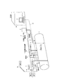
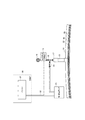
図1は本実施形態の圧力センサを備えた二重殻構造の埋設タンクの例を示す図である。同図において、埋設タンク1には、例えばガソリンを入れる注油管2、地下タンク1からガソリンを吸引する給油管3、埋設タンク1の通気を行う通気管4、及び埋設タンク1に貯蔵されたガソリンの液面高を計測する液面計5が設置されている。また、埋設タンク1は地表から所定の深さに埋設され、埋設タンク1上はコンクリートが施設されている。
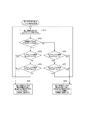
先ず、微少空間26の基準圧力の初期設定を行う。図4はこの処理を説明するフローチャートである。先ず、開閉弁18を開き、開閉弁20を閉じ、圧力変動検知装置16によって微少空間26(圧力検出筒15)の初期圧力を測定する(ステップ(以下、Sで示す)1)。尚、この作業は、例えば作業者が点検口22内に入り、開閉弁18、20を操作し、圧力表示メータ19を目視しながら行う。
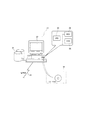
事務所30に設置されたパソコン31は常時圧力変動検知装置16からのデータを受信しており、前述のプログラムに従って圧力変動検知装置16からの圧力情報を監視している(ステップ(以下、STで示す)1)。ここで、例えば本例の初期設定の圧力範囲が大気圧以上に設定されている場合(ST2がYES)、圧力変動検知装置16からの検出データが初期設定のP1〜P2の範囲内であるか判断する。
2・・・注油管
3・・・給油管
4・・・通気管
5・・・液面計
7・・・注油口
8・・・機器類
9、10・・バルブ
12・・通気口
15・・圧力検出筒
16・・圧力変動検知装置
17・・圧力検査用ノズル
18、20・・開閉弁
19・・圧力表示メータ
21・・加減圧ポンプ
22・・点検口
23・・プライマー加工
24・・外殻
25・・内殻
26・・微少空間
30・・事務所
31・・パソコン
32・・信号線
33・・CPU
34・・ROM
35・・RAM
36・・記録装置
38・・記録媒体
Claims (5)
- 内殻と、外殻と、該内殻と外殻間の微少空間の圧力を検知する圧力センサと、を備えた二重殻構造の埋設タンクであって、
前記内殻や外郭に腐蝕や孔蝕を生じ、更に腐蝕穴や孔蝕穴によって前記微少空間の圧力が予め設定した値から外れた場合、前記圧力センサがこれを検知し、埋設タンクの不良を管理者に通知することを特徴とする圧力センサを備えた埋設タンクの二重殻構造。 - 前記圧力センサは、圧力変動検知装置であって、測定値が予め設定した所定値から外れた場合、埋設タンクの不良を管理者に通知することを特徴とする請求項1に記載の圧力センサを備えた埋設タンクの二重殻構造。
- 前記圧力センサ、又は前記圧力変動検知装置の情報は通信回線を介して外部のモニタに送信され、埋設タンクの欠陥表示を前記モニタに行うことを特徴とする請求項1、又は2に記載の圧力センサを備えた埋設タンクの二重殻構造。
- 内殻と、外殻と、該内殻と外殻間の微少空間の圧力を検知する圧力センサと、を備えた二重殻構造の埋設タンクに使用される制御装置に導入するプログラムであって、
前記内殻や外郭に腐蝕や孔蝕を生じ、前記微少空間の圧力が予め設定した値から外れた場合、前記制御装置は前記圧力センサ又は圧力変動検知装置が検知した情報を管理者のパソコンに送信し、パソコンのディスプレイに埋設タンクの欠陥表示を行うことを特徴とする欠陥検出プログラム。 - 内殻と、外殻と、該内殻と外殻間の微少空間の圧力を検知する圧力センサと、を備えた二重殻構造の埋設タンクに使用される制御装置の制御方法であって、
前記内殻や外郭に腐蝕や孔蝕を生じ、前記微少空間の圧力が予め設定した値から外れた場合、前記制御装置は前記圧力センサ又は圧力変動検知装置が検知した情報を管理者のパソコンに送信し、パソコンのディスプレイに埋設タンクの欠陥表示を行うことを特徴とする制御方法。
Priority Applications (1)
| Application Number | Priority Date | Filing Date | Title |
|---|---|---|---|
| JP2019107527A JP2020200068A (ja) | 2019-06-08 | 2019-06-08 | 漏洩検知装置を備えた埋設タンクの二重殻構造 |
Applications Claiming Priority (1)
| Application Number | Priority Date | Filing Date | Title |
|---|---|---|---|
| JP2019107527A JP2020200068A (ja) | 2019-06-08 | 2019-06-08 | 漏洩検知装置を備えた埋設タンクの二重殻構造 |
Publications (1)
| Publication Number | Publication Date |
|---|---|
| JP2020200068A true JP2020200068A (ja) | 2020-12-17 |
Family
ID=73742307
Family Applications (1)
| Application Number | Title | Priority Date | Filing Date |
|---|---|---|---|
| JP2019107527A Pending JP2020200068A (ja) | 2019-06-08 | 2019-06-08 | 漏洩検知装置を備えた埋設タンクの二重殻構造 |
Country Status (1)
| Country | Link |
|---|---|
| JP (1) | JP2020200068A (ja) |
Cited By (1)
| Publication number | Priority date | Publication date | Assignee | Title |
|---|---|---|---|---|
| WO2026048074A1 (ja) * | 2024-08-29 | 2026-03-05 | 株式会社サンフロイント | 漏洩検知装置 |
Citations (3)
| Publication number | Priority date | Publication date | Assignee | Title |
|---|---|---|---|---|
| JPS6323100A (ja) * | 1986-07-02 | 1988-01-30 | ソシエテ・フランセ−ズ・ド・ストッカ−ジュ・ゼオロジック(ゼオストック) | 貯蔵施設およびその耐漏洩性監視方法 |
| JPS63203582A (ja) * | 1987-02-10 | 1988-08-23 | 日本エンヂニヤ−・サ−ビス株式会社 | 漏洩検知機構を有する地下タンク |
| JP2009113859A (ja) * | 2007-11-09 | 2009-05-28 | Tokiko Techno Kk | 二重殻タンクシステム |
-
2019
- 2019-06-08 JP JP2019107527A patent/JP2020200068A/ja active Pending
Patent Citations (3)
| Publication number | Priority date | Publication date | Assignee | Title |
|---|---|---|---|---|
| JPS6323100A (ja) * | 1986-07-02 | 1988-01-30 | ソシエテ・フランセ−ズ・ド・ストッカ−ジュ・ゼオロジック(ゼオストック) | 貯蔵施設およびその耐漏洩性監視方法 |
| JPS63203582A (ja) * | 1987-02-10 | 1988-08-23 | 日本エンヂニヤ−・サ−ビス株式会社 | 漏洩検知機構を有する地下タンク |
| JP2009113859A (ja) * | 2007-11-09 | 2009-05-28 | Tokiko Techno Kk | 二重殻タンクシステム |
Cited By (1)
| Publication number | Priority date | Publication date | Assignee | Title |
|---|---|---|---|---|
| WO2026048074A1 (ja) * | 2024-08-29 | 2026-03-05 | 株式会社サンフロイント | 漏洩検知装置 |
Similar Documents
| Publication | Publication Date | Title |
|---|---|---|
| EP3274619B1 (en) | Apparatus and method for the detection and monitoring of the condition of pipeline components | |
| US20080098801A1 (en) | Method and Apparatus for Continuously Monitoring Interstitial Regions in Gasoline Storage Facilities and Pipelines | |
| US20230094439A1 (en) | Self drilling pressure simulation test device and method for formation containing natural gas hydrate | |
| EP4141402B1 (en) | Structural health monitoring method for fluid containers | |
| JP5044494B2 (ja) | 二重殻タンクの漏洩検査装置 | |
| CN108387346A (zh) | 一种液体火箭发动机推进剂供应管路气密检漏系统及方法 | |
| DE102005008308A1 (de) | Verfahren zur Lecksuche an Leckschutzauskleidungen von Tanks und Behältern o. dgl. | |
| JP2020524810A (ja) | 海底パイプラインで使用するパイプ継手の設計方法 | |
| KR200445590Y1 (ko) | 주유소의 이상 발생 모니터링 장치 | |
| JP2020200068A (ja) | 漏洩検知装置を備えた埋設タンクの二重殻構造 | |
| JP3222717U (ja) | 漏洩検知装置を備えた埋設タンクの二重殻構造 | |
| TWI668168B (zh) | Oil leakage notification method for underground double-layered shell pipe with leak detection and double-shell structure of underground oil tank | |
| US7216530B2 (en) | Fluid containment element leak detection apparatus and method | |
| JP5136299B2 (ja) | 二重殻タンクの漏洩検知装置 | |
| US5347850A (en) | Method for detecting and localizing leaks in above ground storage tanks | |
| KR101414041B1 (ko) | 토양, 지하수 오염방지 유류 저장탱크의 누유 모니터링 방법 | |
| JP2005075400A (ja) | 燃料供給システム | |
| KR101061938B1 (ko) | 연료탱크의 누유 검사 시스템 | |
| Sokolkin et al. | Prospects of applications of acoustic emission methods to testing bottoms of tanks for oil and oil derivatives | |
| US20090165535A1 (en) | Leak localization in a cavitated body | |
| KR20050023062A (ko) | 액체배관의 누설감지 시스템 | |
| CA3216724C (en) | Combustion gas leak detection strategy | |
| US11306647B1 (en) | Combustion gas leak detection strategy | |
| CN120467614B (zh) | 一种地下水污染源渗漏排查用地下管道渗漏性检测装置及方法 | |
| JP3209894U (ja) | 埋設配管の欠陥検出装置 |
Legal Events
| Date | Code | Title | Description |
|---|---|---|---|
| A621 | Written request for application examination |
Free format text: JAPANESE INTERMEDIATE CODE: A621 Effective date: 20220605 |
|
| A131 | Notification of reasons for refusal |
Free format text: JAPANESE INTERMEDIATE CODE: A131 Effective date: 20230724 |
|
| A601 | Written request for extension of time |
Free format text: JAPANESE INTERMEDIATE CODE: A601 Effective date: 20230918 |
|
| A521 | Request for written amendment filed |
Free format text: JAPANESE INTERMEDIATE CODE: A523 Effective date: 20231022 |
|
| A131 | Notification of reasons for refusal |
Free format text: JAPANESE INTERMEDIATE CODE: A131 Effective date: 20240118 |
|
| A02 | Decision of refusal |
Free format text: JAPANESE INTERMEDIATE CODE: A02 Effective date: 20240709 |