JP2020200079A - Hinge cap - Google Patents
Hinge cap Download PDFInfo
- Publication number
- JP2020200079A JP2020200079A JP2019108320A JP2019108320A JP2020200079A JP 2020200079 A JP2020200079 A JP 2020200079A JP 2019108320 A JP2019108320 A JP 2019108320A JP 2019108320 A JP2019108320 A JP 2019108320A JP 2020200079 A JP2020200079 A JP 2020200079A
- Authority
- JP
- Japan
- Prior art keywords
- fixed piece
- side wall
- pair
- elastic plate
- guide
- Prior art date
- Legal status (The legal status is an assumption and is not a legal conclusion. Google has not performed a legal analysis and makes no representation as to the accuracy of the status listed.)
- Granted
Links
Images




Landscapes
- Closures For Containers (AREA)
Abstract
【課題】ヒンジキャップにおいて、キャップ本体に対する開放力・閉鎖力を上蓋に与える弾性板が射出成形時に側壁とは分離している場合に、量産に適した構成にすること。【解決手段】本発明のヒンジキャップは、容器本体に装着するキャップ本体・上蓋・一対のヒンジ・一対のヒンジの間において上蓋から延びる弾性板・一対のヒンジの間において弾性板の先部を側壁に重ね合わせた状態で収容する弾性板用収容部・弾性板用収容部から弾性板の先部が離脱するのを阻止する阻止部を備える。弾性板の先部は側壁に対し重ね合わせた状態で固定されると共に射出成形時においては側壁とは分離した固定片部である。弾性板用収容部は、側壁と協働して固定片部を径方向から挟むようにして案内し且つ固定片部が差し込まれた案内部を備える。固定片部の差込方向は容器本体とは反対側から容器本体側に向かう方向、又は逆方向である。【選択図】 図1PROBLEM TO BE SOLVED: To provide a hinge cap having a configuration suitable for mass production when an elastic plate which gives an opening force / closing force to a cap body to an upper lid is separated from a side wall at the time of injection molding. SOLUTION: The hinge cap of the present invention has a cap body to be attached to a container body, an upper lid, a pair of hinges, an elastic plate extending from the upper lid between the pair of hinges, and a side wall of the tip of the elastic plate between the pair of hinges. The elastic plate accommodating portion and the elastic plate accommodating portion accommodating in a state of being overlapped with each other are provided with a blocking portion for preventing the tip portion of the elastic plate from being detached from the elastic plate accommodating portion. The tip of the elastic plate is fixed to the side wall in a state of being overlapped with each other, and is a fixed piece part separated from the side wall at the time of injection molding. The accommodating portion for the elastic plate includes a guide portion for guiding the fixed piece portion in a radial direction in cooperation with the side wall and into which the fixed piece portion is inserted. The insertion direction of the fixed piece is from the side opposite to the container body toward the container body, or in the opposite direction. [Selection diagram] Fig. 1
Description
本発明は、合成樹脂製のヒンジキャップに関するものである。より詳しくは、容器本体に装着すると共に内容物を排出可能なキャップ本体と、キャップ本体を覆う上蓋と、上蓋をキャップ本体に対して開閉自在に接合するヒンジと、キャップ本体に対する開放力及び閉鎖力を上蓋に付与する弾性板とを備えるヒンジキャップに関する。 The present invention relates to a hinge cap made of synthetic resin. More specifically, a cap body that can be attached to the container body and the contents can be discharged, an upper lid that covers the cap body, a hinge that joins the upper lid to the cap body in an openable and closable manner, and an opening force and a closing force to the cap body. The present invention relates to a hinge cap provided with an elastic plate that imparts the upper lid.
上記した種類の従来のヒンジキャップの一例として、キャップ本体に対して上蓋を弾性板の復元力を利用して大きく開いた状態に保持できるものが存在する(特許文献1参照)。 As an example of the above-mentioned type of conventional hinge cap, there is one that can hold the upper lid in a wide open state by utilizing the restoring force of the elastic plate with respect to the cap body (see Patent Document 1).
特許文献1に開示されたヒンジキャップにおいて弾性板は、上蓋から側壁に向かって延びるものであり、上蓋から側壁に向かって順に、折れ曲がり自在な第1の折れ曲がり部、板バネ部、折れ曲がり自在な第2の折れ曲がり部、側壁に対し重ね合わせた状態で固定された固定部を備えるものである。
In the hinge cap disclosed in
特許文献1の図と文章には、固定部は射出成形時において第2の折れ曲がり部と側壁とに架設するように延びていることが明示されている。より詳しく言えば、固定部は、第2の折れ曲がり部から延びると共に側壁に対し重ね合わせる重ね合わせ部と、側壁から重ね合わせ部とに架設するように延びる第3の折れ曲がり部とを備える。
The figures and texts of
また特許文献1の図には明示されていないが、文章には、固定部は射出成形時において側壁に達しているか否かを問わないことが記載されている。
Further, although not explicitly shown in the figure of
固定部が射出成形時において側壁に達していない場合、どのようにして側壁に固定するのかについては明示されていない。固定するという文言からは、固定する具体的な構成を特定しておらず、多様な構成が含まれる。しかしながら成形のし易さ、成形後の組立て易さが無ければ、量産には不向きとなる。 If the fixed portion does not reach the side wall during injection molding, it is not specified how to fix it to the side wall. The word "fix" does not specify a specific configuration to be fixed, and includes various configurations. However, if it is not easy to mold and assemble after molding, it is not suitable for mass production.
本発明は上記実情を考慮して創作されたものであり、その目的は、弾性板を備えるヒンジキャップにおいて、その弾性板が射出成形時においては側壁とは分離しているものに関して、量産に適した構成にすることである。 The present invention has been created in consideration of the above circumstances, and an object thereof is suitable for mass production of a hinge cap provided with an elastic plate, wherein the elastic plate is separated from the side wall at the time of injection molding. It is to make a structure.
本発明のヒンジキャップは合成樹脂製の一体成形品である。また本発明のヒンジキャップは、容器本体に装着する筒状の側壁、側壁の一方の開口端部を閉鎖する閉鎖板であって内容物の排出穴が形成された閉鎖板を含むキャップ本体と、閉鎖板を覆う上蓋と、キャップ本体と上蓋とを開閉自在に接合すると共にキャップ本体と上蓋の互いの周方向に間隔をあけて配置された一対のヒンジと、一対のヒンジの間においてキャップ本体に対する開放力及び閉鎖力を上蓋に付与する弾性板であってその表面が閉状態において上蓋の表面に沿う曲面である弾性板と、一対のヒンジの間において弾性板の先部を側壁に重ね合わせた状態で収容する弾性板用収容部と、弾性板用収容部から弾性板の先部が離脱するのを阻止する阻止部とを備える。
弾性板は、上蓋からキャップ本体の側壁に向かって延びるものである。また弾性板は上蓋から側壁に向かって順に、折れ曲がり自在な第1の折れ曲がり部、板バネ部、折れ曲がり自在な第2の折れ曲がり部、側壁に対し重ね合わせた状態で固定されると共に射出成形時においては側壁とは分離した固定片部とを備える。
上蓋はその縁部に閉状態における板バネ部を収容する収容穴を備える。
弾性板用収容部は、側壁と協働して固定片部を側壁における径方向から挟むようにして案内する案内部であって固定片部が差込まれた案内部を備える。そして固定片部の差込方向は容器本体とは反対側から容器本体側に向かう方向、又は容器本体側から容器本体とは反対側に向かう方向である。
The hinge cap of the present invention is an integrally molded product made of synthetic resin. Further, the hinge cap of the present invention includes a tubular side wall to be attached to the container body, a closing plate for closing one open end of the side wall, and a cap body including a closing plate in which a discharge hole for contents is formed. The upper lid that covers the closing plate, the cap body and the upper lid are joined openly and closably, and a pair of hinges that are arranged at intervals in the circumferential direction of the cap body and the upper lid, and between the pair of hinges with respect to the cap body. An elastic plate that applies an opening force and a closing force to the upper lid and whose surface is a curved surface along the surface of the upper lid in the closed state, and the tip of the elastic plate overlapped with the side wall between a pair of hinges. It is provided with an elastic plate accommodating portion for accommodating in a state and a blocking portion for preventing the tip of the elastic plate from detaching from the elastic plate accommodating portion.
The elastic plate extends from the upper lid toward the side wall of the cap body. Further, the elastic plate is fixed in order from the upper lid to the side wall in a state of being overlapped with the first bendable portion, the leaf spring portion, the second bendable portion that can be bent, and the side wall, and at the time of injection molding. Provided a fixed piece portion separated from the side wall.
The upper lid is provided with a housing hole at its edge for accommodating the leaf spring portion in the closed state.
The accommodating portion for the elastic plate is a guide portion that guides the fixed piece portion in cooperation with the side wall so as to sandwich the fixed piece portion from the radial direction in the side wall, and includes a guide portion into which the fixed piece portion is inserted. The insertion direction of the fixed piece is a direction from the side opposite to the container body toward the container body, or a direction from the container body side toward the side opposite to the container body.
またヒンジキャップは、上蓋の閉状態の場合、固定片部には容器本体とは反対側に向かって弾性板用収容部から離脱しようとする力が加わる。固定片部の差込方向が容器本体とは反対側から容器本体に向かう方向であると、弾性板用収容部と側壁との間に形成される内部空間は容器本体側に向かって開口することになり、この開口方向は固定片部が離脱しようとする力の加わる方向と一致する。ヒンジキャップの使用の仕方として、上蓋の閉状態の時間の方が開状態の時間よりも長い。従ってこの開口方向の場合は、開口方向が逆向きの場合に比べて、固定片部が弾性板用収容部から離脱し易くなり、量産に不向きである。そこでヒンジキャップを量産に適した構成にするには次のようにすることが望ましい。
すなわち固定片部の差込方向は容器本体側から容器本体とは反対側に向かう方向にすることである。
Further, when the upper lid of the hinge cap is closed, a force is applied to the fixed piece portion toward the side opposite to the container body so as to separate from the elastic plate accommodating portion. When the insertion direction of the fixed piece is from the side opposite to the container body toward the container body, the internal space formed between the elastic plate accommodating part and the side wall opens toward the container body side. This opening direction coincides with the direction in which the force applied to the fixed piece is about to separate. As for how to use the hinge cap, the time when the upper lid is closed is longer than the time when it is open. Therefore, in the case of this opening direction, the fixed piece portion is more likely to be separated from the elastic plate accommodating portion as compared with the case where the opening direction is opposite, which is not suitable for mass production. Therefore, it is desirable to make the hinge cap a configuration suitable for mass production as follows.
That is, the insertion direction of the fixed piece portion is from the container body side to the opposite side to the container body.
また側壁はその外周面を一対のヒンジの間において凹ませるのか突出させるのかを問わないが、ヒンジキャップの径方向の寸法をできるだけ短くし、且つ固定片部を弾性板用収容部に差し込み易くして量産し易くするには次のようにすることが望ましい。ちなみに一対のヒンジの間においては側壁・固定片部・外側案内片部が径方向に順番に重なり合うので、これらの厚みはヒンジキャップの径方向の寸法に影響を与える。
すなわち側壁はその外周面のうち一対のヒンジの間には径方向内側に向かって凹むと共に固定片部本体を重ね合わせる外周凹部を備えるものとする。そして外周凹部は一対のヒンジの間から一対のヒンジに対して容器本体側に向かって延びるものとする。
Further, although it does not matter whether the outer peripheral surface of the side wall is recessed or projected between the pair of hinges, the radial dimension of the hinge cap is made as short as possible, and the fixing piece portion is easily inserted into the accommodating portion for the elastic plate. It is desirable to do the following to facilitate mass production. Incidentally, since the side wall, the fixed piece, and the outer guide piece overlap in order in the radial direction between the pair of hinges, these thicknesses affect the radial dimensions of the hinge cap.
That is, the side wall is provided with an outer peripheral recess in which a pair of hinges on the outer peripheral surface are recessed inward in the radial direction and the main body of the fixed piece is overlapped. Then, the outer peripheral recess extends from between the pair of hinges toward the container body with respect to the pair of hinges.
また案内部はどのような構成であるのか問わないし、固定片部と第2の折れ曲がり部とがどのように接合しているかを問わないが、固定片部を弾性板用収容部に差し込む作業に、固定片部と第2の折れ曲がり部との接合位置が影響を与える。例えば、一対のヒンジに対して容器本体側において側壁に重ね合わせた上で、固定片部のうち容器とは反対側の端部を治具で押し込んで、弾性板用収容部に差し込む場面を想定する。仮に第2の折れ曲がり部が固定片部のうち容器本体側の端部に接合している場合は、第2の折れ曲がり部や板バネが案内部に衝突しないようにして、固定片部を案内部に差し込まなければならない。固定片部を案内部に差し込み易くして、量産し易くするには次のようにすることが望ましい。
すなわち案内部は、固定片部における前記周方向の両側部を別々に案内すると共に周方向に向かって対向する状態で開口する一対の案内溝部と、一対の案内溝部の間に形成されると共に第2の折れ曲がり部を通過させる窓部とを備える。そして上蓋の閉状態において固定片部は、側壁の筒状の貫通方向に延びる固定片本体部であって容器本体とは反対側において且つ周方向の中間部に第2の折れ曲がり部が接合した固定片本体部と、固定片本体部から容器本体とは反対側に延びると共に案内溝部に対し固定片本体部よりも先行して差し込まれる先行部とを備えることである。
In addition, it does not matter what kind of structure the guide part has, and it does not matter how the fixed piece part and the second bent part are joined, but for the work of inserting the fixed piece part into the elastic plate accommodating part. , The joint position between the fixed piece and the second bent part has an effect. For example, it is assumed that a pair of hinges are overlapped on the side wall on the container body side, and then the end of the fixed piece on the side opposite to the container is pushed in with a jig and inserted into the elastic plate accommodating portion. To do. If the second bent part is joined to the end of the fixed piece on the container body side, the fixed piece is guided by preventing the second bent part and the leaf spring from colliding with the guide part. Must be plugged into. In order to make it easier to insert the fixed piece into the guide and mass-produce it, it is desirable to do the following.
That is, the guide portion is formed between the pair of guide groove portions and the pair of guide groove portions that separately guide both side portions in the circumferential direction of the fixed piece portion and are opened in a state of facing each other in the circumferential direction. It is provided with a window portion through which the second bent portion is passed. When the upper lid is closed, the fixed piece portion is a fixed piece main body portion that extends in the tubular penetrating direction of the side wall, and is fixed by joining a second bent portion to the middle portion in the circumferential direction on the side opposite to the container main body. It is provided with a single main body portion and a leading portion extending from the fixed piece main body portion to the opposite side of the container main body and being inserted into the guide groove portion in advance of the fixed piece main body portion.
また阻止部は弾性板用収容部から弾性板の先部が離脱するのを阻止する構成であれば良く、差し込んだ弾性板を弾性板用収容部に溶着や接着等するものであってもよいが、作業の容易による量産のし易さを考慮すれば、次のようにすることが望ましい。
すなわち阻止部は、案内部の内部空間に対し容器本体とは反対側へ位置すると共に容器本体とは反対側への固定片部の移動を阻止する第1の阻止部と、固定片部と嵌合すると共に容器本体側への固定片部の移動を阻止する第2の阻止部とを備えることである。
Further, the blocking portion may have a configuration that prevents the tip of the elastic plate from coming off from the accommodating portion for the elastic plate, and the inserted elastic plate may be welded or adhered to the accommodating portion for the elastic plate. However, considering the ease of mass production due to the ease of work, it is desirable to do the following.
That is, the blocking portion is located on the side opposite to the container body with respect to the internal space of the guide portion, and is fitted with the first blocking portion that blocks the movement of the fixed piece portion to the side opposite to the container body, and the fixing piece portion. It is provided with a second blocking portion that fits and blocks the movement of the fixed piece portion toward the container body side.
また第1の阻止部は側壁と案内溝部に接合されたものであるか否かを問わないが、容器本体とは反対側への固定片部の移動を強固に阻止するには次のようにすることが望ましい。
すなわち第1の阻止部は、側壁と案内溝部との間に形成される内部空間を容器本体とは反対側で外部と仕切ると共に、側壁と案内溝部とに接合されるものにすることである。
Further, the first blocking portion may or may not be joined to the side wall and the guide groove portion, but in order to firmly prevent the movement of the fixed piece portion to the side opposite to the container body, it is as follows. It is desirable to do.
That is, the first blocking portion is to partition the internal space formed between the side wall and the guide groove portion from the outside on the side opposite to the container body, and to join the side wall and the guide groove portion.
また案内部は、固定片部に関して周方向の全長のうちどの部位を案内するのかを問わないし、一対のヒンジとは別に独立したものであるか否かを問わない。ちなみに弾性板は一対のヒンジの間に配置される。そして案内部がヒンジとは別に独立したものである場合、案内部を一対のヒンジに対して周方向に離して形成しなければならず、一対のヒンジキャップの間がより離れ、ヒンジキャップの外観が悪化する。そこでヒンジキャップの外観を良好なものにするには次のようにすることが望ましい。
すなわち、案内部は、固定片部における前記周方向の両側部を別々に案内すると共に周方向に向かって対向する状態で開口する一対の案内溝部を備えるものとする。そして一対の案内溝部は、側壁から周方向に離隔する状態で径方向外側に突出すると共に固定片部を周方向の両側から案内する一対の周側案内片部と、一対の周側案内片部における前記径方向外側から双方の間隔を狭める方向に突出すると共に固定片部を前記径方向外側から案内する一対の外側案内片部とを備えるものとする。そのうえで一対の周側案内片部は一対のヒンジの一部を用いることにする。
Further, the guide portion does not matter which part of the total length in the circumferential direction is guided with respect to the fixed piece portion, and does not matter whether the guide portion is independent of the pair of hinges. By the way, the elastic plate is arranged between the pair of hinges. When the guide portion is independent of the hinge, the guide portion must be formed so as to be separated from the pair of hinges in the circumferential direction, and the pair of hinge caps are further separated from each other, and the appearance of the hinge cap is increased. Get worse. Therefore, in order to improve the appearance of the hinge cap, it is desirable to do the following.
That is, the guide portion is provided with a pair of guide groove portions that separately guide both side portions of the fixed piece portion in the circumferential direction and open in a state of facing each other in the circumferential direction. The pair of guide groove portions protrude outward in the radial direction while being separated from the side wall in the circumferential direction, and the pair of peripheral guide pieces and the pair of peripheral guide pieces that guide the fixed piece from both sides in the circumferential direction. It is assumed that a pair of outer guide pieces are provided so as to project from the outer side in the radial direction in the above direction and guide the fixed piece portion from the outer side in the radial direction. Then, a part of the pair of hinges is used for the pair of peripheral guide pieces.
本発明のヒンジキャップは、上蓋から側壁に向かって延びる弾性板を射出成形時においては側壁とは分離し、弾性板の先部としての固定片部の差込方向を容器本体とは反対側から容器本体側に向かう方向、又は容器本体側から容器本体とは反対側に向かう方向にしてあるので、キャップ本体の側壁の貫通方向、つまり金型の型開き方向と同じであり、射出成形し易く、量産に適している。 In the hinge cap of the present invention, the elastic plate extending from the upper lid toward the side wall is separated from the side wall during injection molding, and the insertion direction of the fixed piece portion as the tip of the elastic plate is from the side opposite to the container body. Since the direction is toward the container body side or from the container body side to the side opposite to the container body, it is the same as the penetrating direction of the side wall of the cap body, that is, the mold opening direction, and is easy to injection mold. , Suitable for mass production.
また本発明のヒンジキャップは、固定片部の差込方向を容器本体側から容器本体とは反対側に向かう方向にしたものであれば、上蓋の閉状態において固定片部が弾性板用収容部から離脱し難くなり、量産に適している。 Further, in the hinge cap of the present invention, if the insertion direction of the fixed piece portion is directed from the container body side to the side opposite to the container body, the fixed piece portion is the accommodating portion for the elastic plate when the upper lid is closed. It is difficult to separate from and is suitable for mass production.
また本発明のヒンジキャップは、側壁の外周面のうち一対のヒンジの間を外周凹部としたものであれば、例えば側壁の外周面のうち一対のヒンジの間を径方向内側に凹ませることなく一対のヒンジに対して周方向の両隣りと同様に形成したヒンジキャップと比べれば、外周凹部の凹み量の分だけ、外側案内片部が径方向内側に位置することになり、ヒンジキャップの径方向の寸法が短くなる。しかも外周凹部を備えるヒンジキャップは、外周凹部が一対のヒンジの間から一対のヒンジに対して容器本体側に向かって延びているので、固定片部を容器本体側へ差し込むときに、例えば外周凹部が一対のヒンジの間にのみ形成されているヒンジキャップと比べれば、固定片部が径方向に移動せずに済むので、固定片部を弾性板用収容部に差し込み易くなり、量産に適している。 Further, if the hinge cap of the present invention has an outer peripheral recess between a pair of hinges on the outer peripheral surface of the side wall, for example, the space between the pair of hinges on the outer peripheral surface of the side wall is not recessed inward in the radial direction. Compared to the hinge caps formed on both sides of the pair of hinges in the circumferential direction, the outer guide piece is located inward in the radial direction by the amount of the recess in the outer peripheral recess, and the diameter of the hinge cap. The dimension in the direction becomes shorter. Moreover, in the hinge cap provided with the outer peripheral recess, the outer peripheral recess extends from between the pair of hinges toward the container body side with respect to the pair of hinges, so that when the fixing piece is inserted into the container body side, for example, the outer peripheral recess Compared to a hinge cap that is formed only between a pair of hinges, the fixed piece does not have to move in the radial direction, so it is easier to insert the fixed piece into the elastic plate accommodating part, which is suitable for mass production. There is.
また本発明のヒンジキャップは、固定片部が固定片本体部と先行部とを備えるものであれば、第2の折れ曲がり部よりも先行部が容器本体とは反対側に延びているので、固定片部を弾性板用収容部へ差し込むときに、先行部が一対の案内溝部に先に差し込まれ、しかも第2の折れ曲がり部が一対の案内溝部の間の窓部に位置して一対の案内溝部に衝突しないので、固定片部を弾性用収容部に差し込み易くなり、量産に適している。 Further, in the hinge cap of the present invention, if the fixed piece portion includes the fixed piece main body portion and the leading portion, the leading portion extends from the second bent portion to the side opposite to the container main body, so that the hinge cap is fixed. When one part is inserted into the elastic plate accommodating portion, the leading portion is inserted into the pair of guide groove portions first, and the second bent portion is located at the window portion between the pair of guide groove portions, and the pair of guide groove portions. Since it does not collide with the elastic housing, it is easy to insert the fixed piece into the elastic housing, which is suitable for mass production.
また本発明のヒンジキャップは、阻止部が第1・第2の阻止部を備えるものであれば、容器本体とは反対側への固定片部の移動が当該反対側に位置する第1の阻止部によって阻止され、容器本体側への固定片部の移動が第2の阻止部と固定片部との嵌合によって阻止されるので、固定片部を弾性板用収容部に差し込むだけで固定片部が弾性板用収容部から離脱するのを阻止できるので、例えば差し込み作業の他に弾性板を弾性板用収容部に溶着や接着等するものに比べて、作業が容易であり、量産に適している。 Further, in the hinge cap of the present invention, if the blocking portion includes the first and second blocking portions, the movement of the fixed piece portion to the opposite side of the container body is located on the opposite side of the first blocking portion. Since the fixing piece is blocked by the portion and the movement of the fixing piece to the container body side is blocked by the fitting of the second blocking portion and the fixing piece, the fixing piece is simply inserted into the elastic plate accommodating portion. Since the portion can be prevented from being separated from the elastic plate accommodating portion, the work is easier and more suitable for mass production than, for example, in addition to the insertion work, in which the elastic plate is welded or adhered to the elastic plate accommodating portion. ing.
また本発明のヒンジキャップは、第1の阻止部の構成に関して側壁と案内溝部との間に形成される内部空間を容器本体とは反対側で外部と仕切る構成のものにすれば、例えば第1の阻止部が側壁と案内壁部に接合されているので、第1の阻止部が側壁と案内壁部のうち一方にのみ接合されているものと比べれば、第1の阻止部が強固に接合されており、容器本体とは反対側への固定片部の移動を強固に阻止することができる。 Further, the hinge cap of the present invention has a configuration in which the internal space formed between the side wall and the guide groove portion is partitioned from the outside on the side opposite to the container body with respect to the configuration of the first blocking portion, for example, the first. Since the blocking portion of the above is joined to the side wall and the guide wall portion, the first blocking portion is firmly joined as compared with the case where the first blocking portion is joined to only one of the side wall and the guide wall portion. It is possible to firmly prevent the movement of the fixed piece portion to the side opposite to the container body.
また本発明のヒンジキャップは、案内部を一対の案内溝部を備えるものとし、一対の案内溝部のうち一対の周側案内片部に一対のヒンジの一部を用いるものであれば、例えば案内部がヒンジとは別に独立したものである場合に比べて、案内部とヒンジとが一体になっているので、外観が良好になる。 Further, in the hinge cap of the present invention, if the guide portion is provided with a pair of guide groove portions and a part of the pair of hinges is used for the pair of peripheral guide piece portions of the pair of guide groove portions, for example, the guide portion. Since the guide portion and the hinge are integrated as compared with the case where the hinge is independent from the hinge, the appearance is improved.
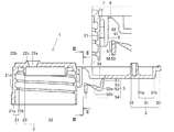
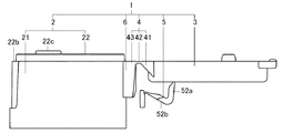
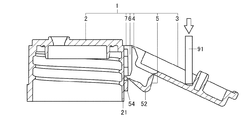
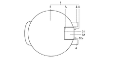
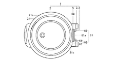
本発明の第一実施形態のヒンジキャップ1は合成樹脂製の一体成形品であって、図1,8,10に示すように、容器本体(図示略)に装着すると共に内容物を排出可能なキャップ本体2と、キャップ本体2を開閉する上蓋3と、キャップ本体2と上蓋3を開閉自在に接合する一対のヒンジ4と、キャップ本体2に対する開放力及び閉鎖力を上蓋3に付与する弾性板5と、一対のヒンジ4,4の間において弾性板5の先部をキャップ本体2の外周面に重ね合わせた状態で収容する弾性板用収容部6と、弾性板用収容部6から弾性板5の先部が離脱するのを阻止する阻止部7とを備えるものである。なお容器本体は、一例として底の有る筒状であり、その口部は筒状となっている。また以下では、図10〜14に示すように上蓋3が閉じている状態、つまり閉状態を基本的形態とする。そして特に断りがない場合には、閉状態について説明しているものとする。
The
図1〜5は射出成形用の金型内のヒンジキャップ1を示している。キャップ本体2は、容器本体の口部に装着する筒状の側壁21と、側壁21の貫通方向のうち一方向(容器本体とは反対方向)の開口端部の内周側を閉鎖する閉鎖板22と、閉鎖板22から側壁21の貫通方向のうち他方向(容器本体の方向)へ延長すると共に側壁21の内面に対し間隔をあけて配置された筒状の内周壁23とを備える。なお図示の例では、貫通方向のうち一方向を上方向、他方向を下方向としてある。また図示の例では、容器本体から容器本体とは反対側に向かう方向は上方向であり、容器本体とは反対側から容器本体側へ向かう方向は下方向である。また筒状をなす側壁21の径方向を以下では径方向と称する。
FIGS. 1 to 5 show a
側壁21は、円筒状の側壁本体21aと、側壁本体21aを容器本体の口部に連結する連結部21bとしての雌ネジ部21bを備えている。雌ネジ部21bは、側壁本体21aの内周面からその全周に亘って螺旋状に突出している。また側壁本体21aの上部の外周面にはその周方向における位置に関して弾性板5とは反対側において、径方向内側へ向かって窪む窪み部21dを備えている。
The
閉鎖板22は、その縁部(径方向外側、外周部とも言う。)が側壁本体21aの上端部に対しその全周に亘って接合(連続)している。また閉鎖板22には、板の厚み方向である上下方向に貫通する排出穴22aが形成されている。また閉鎖板22には容器本体とは反対側の面(上面)からノズル22cが突出しており、ノズル22cの内部空間は排出穴22aに通じている。なお閉鎖板22の上面の縁部22bは、それよりも径方向内側に比べて段差状に低くなっており、この低い面が上蓋3の縁部(外周部)の端面との接触面となる。
The edge portion (also referred to as radial outer side and outer peripheral portion) of the
内周壁23は側壁21の中心と同心状に形成されている。また内周壁23の下端は雌ネジ部21bの下端よりも上側の位置となっている。また内周壁23と側壁21との径方向の間隔は、容器本体の口部の上端部が収容される長さに設定してある。
The inner
上蓋3は、排出穴22aを含めて閉鎖板22を覆う上蓋本体31と、上蓋本体31からキャップ本体2側へ突出すると共に排出穴22aの内側に対し上蓋3の開閉に伴って出入りする突起32と、上蓋本体31の縁部から径方向外側(外周側)へ突出する鍔33とを備える。
The
上蓋本体31は図示の例では上板31aと、上板31aの外周縁の全周からキャップ本体2側へ向かって突出する上枠31bとを備える。
上板31aは閉鎖板22と同じ形状の板状である。
上枠31bは、上板31aの外周全周に沿う環状に形成されている。この環状の端面(下端面)が、キャップ本体2の閉鎖板22の外周縁部への接触面となる。
In the illustrated example, the upper lid
The
The
鍔33は、上枠31bの外周面のうち側壁21の窪み部21dに対応する位置から径方向外側へ向かって突出している。
また上板31aと上枠31bには、その周方向のうち鍔33とは反対側において互いの周方向に沿って順番にヒンジ4・弾性板5・ヒンジ4が配置されている。そして弾性板5を配置するために、上板31aと上枠31b(上蓋3の縁部)には、鍔33とは反対側において、上板31aの外周部から上枠31bの下端面に達するまで恰も切り欠いたかのように径方向内側に向かって凹む切欠凹部34が形成されている。この切欠凹部34の内側の空間には閉状態において弾性板5の一部(後述する第1の折れ曲がり部51、板バネ部52)が配置される。言い換えれば切欠凹部34は閉状態において板バネ部52を収容する収容穴34である。
The
Further, on the
ヒンジ4は、上蓋3から側壁21に向かって順に、上蓋3に対し径方向外側に突出する第1の片部41、第1の片部41に対し厚みの薄いヒンジ部本体42、側壁21に対し径方向外側に突出する第2の片部43を備える。なおヒンジ部本体42は、第1の片部41と第2の片部43とに接合しており、上蓋3が開閉するときの(回転運動をするときの)中心部となり、第2の片部43に対しても厚みを薄くしてある。
The
弾性板5は板状であって、いわゆる板バネとして機能する。また弾性板5は、上蓋3から側壁21に向かって延びており、その一端が上蓋3に対し接合されると共に、その他端が射出成形時において側壁21に対し分離した状態であり且つ射出成形後において側壁21に対し重ね合わせた状態で固定されている。また弾性板5は、上蓋3から側壁21に向かって順に、折れ曲がり自在な第1の折れ曲がり部51、板バネ部52、折れ曲がり自在な第2の折れ曲がり部53、射出成型後に側壁21の外周面の上部(容器本体とは反対側)に重ね合わせた状態で固定された固定片部54を備える。
The
なお上蓋3が開閉するときには弾性板5(板バネ部52)は弾性変形しながら回転運動するが、その回転運動するときの中心部となるのが第2の折れ曲がり部53である。そして上蓋3が開閉するときに弾性板5(板バネ部52)を弾性変形させるために、弾性板5の回転運動の中心部(第2の折れ曲がり部53)は上蓋3の回転運動の中心部(ヒンジ4のヒンジ部本体42)に対して偏心している。偏心状態は具体的には以下の通りである。
When the
第2の折れ曲がり部53は、筒状である側壁21の貫通方向に関しては、ヒンジ部本体42に対して貫通方向の他方向(下方向)の開口端部側に偏心して、より詳しく言えば、さらに閉鎖板22の下面よりも当該他方向の開口端部側に偏心して配置されている。また第2の折れ曲がり部53は、筒状である側壁21の径方向に関しては、ヒンジ部本体42に対して径方向内側に偏心して配置されている。
また第2の折れ曲がり部53に対して弾性板5の長手方向の一端には板バネ部52が接合され、他端には固定片部54が接合されている。
The second
A
固定片部54は、第2の折れ曲がり部53から延びると共に、第2の折れ曲がり部53よりも厚くしてある。固定片部54は、射出成形時には側壁21とは分離しているが、射出成形後には側壁21に重ね合わせて固定されている。なお固定片部54の詳細は後述の弾性板用収容部6と一緒に説明する。
The fixed
板バネ部52の表面(弾性板5の表面)は、閉状態において上蓋3の表面に沿う状態である。したがって弾性板5の表面と上蓋3の表面とは、段差のない状態、または段差が板バネ部52の厚みよりも短い寸法の範囲内の状態になっている。
また閉状態において、上蓋3の縁部の表面は曲面であり、弾性板5(特に板バネ部52)の表面も対応する曲面となる。図示の例では上蓋3の縁部の表面は屈曲面(上面と外周面とが屈曲して連続する面)、より詳しく言えばL字状の屈曲面であり、弾性板5(特に板バネ部52)の表面も屈曲面(L字状の屈曲面)となっている。
また板バネ部52は、図示の例ではL字状に屈曲する形の板状である。より詳しく言えば板バネ部52は図10に示すように、上蓋3の径方向の中央側から外側に向かって径方向に延びる第1の板バネ片部52aと、第1の板バネ片部52aの径方向の外側端部から側壁21の貫通方向の他方向に向かって延びる第2の板バネ片部52bとを備える形の板状である。また図12,13に示すように第1の折れ曲がり部51の幅(周方向の幅)と第1の板バネ片部52aの幅と第2の板バネ片部52bの上部の幅とは、収容穴34に接するようにしてある。第2の板バネ片部52bの下部の幅は、第2の板バネ片部52bの上部の幅よりも周方向の両側に短くなっており、収容穴34とは離れた状態になっている。
The surface of the leaf spring portion 52 (the surface of the elastic plate 5) is in a state of being along the surface of the
Further, in the closed state, the surface of the edge portion of the
Further, the
また図8に示すように開状態において第2の折れ曲がり部53を介して固定片部54と板バネ部52との間に形成される角度は、鋭角以下、図示の例では0度、いわゆる平行になっている。
Further, as shown in FIG. 8, the angle formed between the
第1、第2の折れ曲がり部51、53は、板バネ部52に対し厚みの薄いものである。このような弾性板5の先部としての固定片部54を収容するのが弾性板用収容部6である。
The first and second
弾性板用収容部6は、2つのヒンジ4,4における2つの第2の片部43,43の間に形成されている(図2参照)。また図12に示すように2つのヒンジ4,4は、上蓋3の外周面から平行に突出している。そして閉状態においてヒンジキャップ1を上側から視たときに、弾性板用収容部6の外周面は一対のヒンジ4,4の外周面よりも径方向の内側に配置されている。
The elastic plate
弾性板用収容部6は側壁21の外周面から突出すると共に、弾性板5の固定片部54を側壁21の外周面に重ね合わせた状態で収容する。弾性板用収容部6は、径方向に関しては射出成形後に側壁21(側壁本体21a)と協働して固定片部54を挟むようにして案内する案内部61であって、周方向に関しては案内部61自身のみで固定片部54を挟むようにして案内する案内部61を備える。
The elastic plate
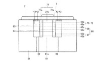
案内部61は図2,8,9に示すように上方に向かって(容器本体側から容器本体とは反対側に向かって)固定片部54が差込まれたものである。また案内部61は固定片部54における前記周方向の両側部を射出成形後に別々に案内する一対の案内溝部62,62と、一対の案内溝部62,62の間に形成されると共に第2の折れ曲がり部53を射出成形後に通過させる窓部61aとを備える。
As shown in FIGS. 2, 8 and 9, the
一対の案内溝部62,62は筒状をなす側壁21の貫通方向である上下方向に延び、周方向に向かって対向する状態で開口する。また一対の案内溝部62,62は固定片部54を周方向の両側および径方向外側から案内する。ちなみに固定片部54を径方向内側から案内するのは側壁21(側壁本体21a)である。また案内溝部62は、固定片部54を周方向の片側から案内する周側案内片部63と、固定片部54を前記径方向外側から案内する外側案内片部64とを備える。
The pair of
一対の周側案内片部63,63は側壁21(側壁本体21a)から周方向に離隔する状態で径方向外側に突出する。また本実施形態では一対の周側案内片部63,63は一対のヒンジ4,4の一部(一対の第2の片部43,43)でもある。
The pair of
一対の外側案内片部64,64は一対の周側案内片部63,63における前記径方向外側から双方の間隔を狭める方向に突出する。本実施形態では一対の外側案内片部64,64が周方向に離隔しており、この離隔している部分は前記した窓部61aである。なお一対の外側案内片部64,64と側壁21との径方向の間隔は、固定片部54の厚みよりも僅かに大きくしてある。
The pair of
また図14に示すように外側案内片部64が固定片部54を径方向外側から案内するものなので、外側案内片部64がないキャップ本体と比べると、キャップ本体2は径方向の寸法が大きくなる。そこでキャップ本体2の径方向の寸法をできるだけ小さくするために、側壁21(側壁本体21a)はその外周面のうち一対のヒンジ4,4(一対の第2の片部43,43)の間に径方向内側に向かって凹むと共に固定片部54を重ね合わせる外周凹部21cを備える。そして側壁21の厚みは、外周凹部21cの部分が外周凹部21cに対する周方向の両側の部分よりも薄くなっている。
Further, as shown in FIG. 14, since the outer
外周凹部21cは図2,9に示すように一対のヒンジ4,4の間だけでなく、ヒンジ4よりも下側にまで連続して形成されている。また外周凹部21cの上部は一対のヒンジ4,4の間に位置し、外周凹部21cの上部に対して周方向の両側には一対の外側案内片部64,64が配置されている。そして一対の外側案内片部64,64を含む一対の案内溝部62,62の下端側と側壁21とは協働して、固定片部54を差し込む入口用の開口を形成する。この開口から差し込まれた固定片部54が一対の案内溝部62,62(案内部61)から上下方向に離脱するのを阻止するのが阻止部7である。
As shown in FIGS. 2 and 9, the outer
阻止部7は図9に示すように、案内部61に収容された固定片部54の容器本体とは反対側(上方)への移動を阻止する第1の阻止部71と、案内部61に収容された固定片部54の容器本体側(下方)への移動を阻止する第2の阻止部72とを備える。
As shown in FIG. 9, the blocking
第1の阻止部71は、側壁21と案内溝部62との間に形成される内部空間を容器本体とは反対側(上方)で外部と仕切ると共に、側壁21と案内溝部62とに接合される。より詳しく言えば、第1の阻止部71は一対の案内溝部62,62の上端部と側壁21との間を別々に上下方向に仕切る一対の仕切板71a,71aである。
The
第2の阻止部72は図2,3,9に示すように、案内部61と固定片部54とを凹凸によって嵌合させる嵌合凹部73と嵌合凸部74である。嵌合凹部73は案内部61と固定片部54の一方に、嵌合凸部74は案内部61と固定片部54の他方に形成される。また本実施形態では嵌合凹部73と嵌合凸部74の凹凸の方向は周方向である。
As shown in FIGS. 2, 3 and 9, the second blocking portion 72 is a fitting recess 73 and a
嵌合凹部73は案内部61の上部に形成される。詳しく言えば嵌合凹部73は、一対の周側案内片部63,63における上部の一対の対向面63a,63aによって形成される。当該一対の対向面63a,63aは、双方の周方向の間隔が上方に向かうにつれて大きくなる状態に傾斜した傾斜面である。当該一対の対向面63a,63aは左右対称である。また当該一対の対向面63a,63aの傾斜角度は、上下方向に対して僅か(10度以内)に傾斜した角度で、図9では傾斜していることが判別できない程度である。
The fitting recess 73 is formed in the upper part of the
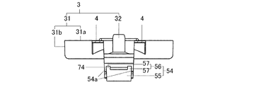
嵌合凸部74は図2,3,9に示すように固定片部54の周方向における一対の側面54a,54aである。当該一対の側面54a,54aは、一対の周側案内片部63,63における一対の対向面63a,63aに対応させて、双方の周方向の寸法が上方に向かうにつれて大きくなる状態に傾斜した傾斜面としてある。したがって嵌合凸部74の上端部における周方向の寸法が嵌合凹部73の下端部における周方向の間隔よりも大きくなっており、寸法的には固定片部54を案内部61の上部に差し込めない状態になっている。そこで固定片部54を案内部61に差し込むときには、固定片部54と案内部61との弾性変形を利用する。弾性変形は固定片部54と案内部61の合成樹脂の弾性によって得られる。
As shown in FIGS. 2, 3 and 9, the fitting
また嵌合凹部73は案内部61の上部に形成されている。また案内部61の下部には嵌合凹部73へ固定片部54を導入する導入部66が形成されている。つまり案内部61は、その上部に嵌合凹部73を備え、その下部に導入部66を備えるものである。
The fitting recess 73 is formed in the upper part of the
導入部66は、その下部には固定片部54を周方向に関して差込み易くする差込部67を備え、その上部には差込部67から嵌合凹部73へ固定片部54を導入する導入部本体68を備える。
The
導入部本体68は、一対の周側案内片部63,63の上下に関する中間部の一対の対向面63c,63cによって形成される。当該一対の対向面63c,63cは、双方の間隔が上方へ向かって徐々に小さくなるものである。言い換えれば導入部本体68の周方向の間隔は、差込部67から嵌合凹部73に向かって徐々に小さくなり、差込部67から嵌合凹部73の下端へ固定片部54を導入する。
The introduction portion
差込部67は、一対の周側案内片部63,63における下部の一対の対向面63b,63bによって形成される。また差込部67の周方向の間隔は、固定片部54の周方向における最大寸法よりも大きくしてあり、固定片部54を差し込み易くしてある。また差込部67は、嵌合凹部73の真下に対して周方向の両側に広がって形成されている。また差込部67へ差し込みやすくするための構成が固定片部54に設けられている。
The
上蓋3の閉状態において固定片部54は図3,9に示すように、上下方向に延びると共に容器本体とは反対側(上部)に第2の折れ曲がり部53が接合した固定片部本体55と、固定片部本体55から上方に突出すると共に案内部61に対し固定片部本体55よりも先行して差し込まれる先行部56とを備える。
固定片部本体55は図1に示すようにその上部における径方向外側に第2の折れ曲がり部53が接合している。
先行部56は、固定片部本体55における周方向の両側部の上面から上方に突出する一対の突出片部57,57である。
In the closed state of the
As shown in FIG. 1, the fixed piece
The leading
また以下では、キャップ本体2と上蓋3とで形成される角度を、開口角度θというものと定める。そして上蓋3の閉状態での開口角度θを0度と定める。また上蓋3の開状態での開口角度θを全開角度というものと定める。そうすると開口角度θが0度と全開角度(図示の例では180度よりも大きな角度)との間の角度の状態、いわゆるヒンジキャップ1の半開き状態においては、板バネ部52のL字状の屈曲角度が、全閉状態の場合の角度(約90度の角度)よりも広がる。この板バネ部52の広がった状態が、板バネ部52の復元力になる。そして半開き状態においては、所定の開口角度θ(90度よりも大きく且つ180度よりも小さい角度)を境にして、復元力は、上蓋3を開放しようとする力(開放力)や閉鎖しようとする力(閉鎖力)に変わるようになる。
Further, in the following, the angle formed by the
上記した説明でのヒンジキャップ1は、固定片部54を側壁21の外周面に対し重ね合わせた状態で固定されており、図8に示すように全開角度が180度よりも大きなものである。しかしヒンジキャップ1は射出成形時においては、図1に示すように開口角度θが180度の状態である。このとき弾性板5は、第1、第2の折れ曲がり部51,53において折れ曲がった状態、あたかもN字状に折れ曲がった状態となっている。より詳しく言えば、N字状は、板バネ部52のV字状と固定片部54のI字状とが第2の折れ曲がり部53で接合された状態である。そして金型設計において、弾性板5の先端が射出成形時においては側壁21とは分離していることから、例えば弾性板5が射出成形時において上蓋3と側壁31とに接合されたものと比べると、板バネ部52のV字状の内角(図での鋭角)を設計し易くなる。また板バネ部52のV字状の内角は、キャップの閉状態における上蓋3の閉鎖力に影響があるので、弾性板5の先端が射出成形時において側壁21とは分離していることは、上蓋3の閉鎖力を設計し易くなると言える。
The
また弾性板用収容部6と側壁21との間に形成される内部空間は下方に向かって通じる状態である。弾性板用収容部6と側壁21との間に形成される内部空間および弾性板5は、成形においていわゆるアンダーカットが無い状態である。そして弾性板5が射出成形時においては側壁21とは分離し、弾性板5の先部としての固定片部54の差込方向を上方(容器本体側から容器本体とは反対側に向かう方向)にしてあるので、キャップ本体2の側壁21の貫通方向、つまり金型の型開き方向と同じであり、射出成形し易く、量産に適している。したがって射出成形後に金型からヒンジキャップ1を取り出しやすい。
Further, the internal space formed between the elastic plate
射出成形後に固定片部54を弾性板用収容部6に固定して組み立てる。組立手順は以下の通りである。
1)まず金型からヒンジキャップ1を取り出す。そうすると、ヒンジ4を中心に上蓋3は開閉可能になる。
2)次に図6に示すように筒状をなす側壁21の貫通方向が上下方向を向く状態にヒンジキャップ1を保持したまま、上蓋3を下方へ治具91で押し込む。そうすると、ヒンジ4のヒンジ部本体42を中心にして上蓋3が開口角度を大きくするように回転し、固定片部54がヒンジ4よりも下側において側壁21の外周面(外周凹部21c)に衝突して重なり合う状態になる。
3)次に図7に示すように別の治具92で固定片部54をその下端面から上方へ押し込む。そうすると、固定片部54は外周凹部21cに重なり合ったまま移動して、弾性板用収容部6に差し込まれ、最終的に弾性板用収容部6の案内部61の嵌合凹部73と固定片部54の嵌合凸部74とが嵌合する。固定片部54が弾性板用収容部6に固定されると、上蓋3の開閉時における弾性板5の回転運動における中心部は、第2の折れ曲がり部53になる。
4)最後にヒンジキャップ1がまだ温かいうちに上蓋3を一旦閉じる。
5)充分に冷ました後に開くと、図8に示すように開口角度θは180度よりも大きくなる。ちなみに組み立てられた閉状態のヒンジキャップ1から固定片部54の形態を検証する場合には、固定片部54を図示しない治具で下方へ押し、弾性板用収容部6から離脱させる。そうすると、弾性板5は、射出成形時の状態に近似した形態となっている。つまり弾性板5は上蓋3に対して上方に配置され、しかも第1、第2の折れ曲がり部51,53において折れ曲がった状態、つまりN字状に折れ曲がった状態となっている。
After injection molding, the fixed
1) First, take out the
2) Next, as shown in FIG. 6, the
3) Next, as shown in FIG. 7, the fixing
4) Finally, close the
5) When opened after sufficiently cooling, the opening angle θ becomes larger than 180 degrees as shown in FIG. By the way, when verifying the form of the fixed
第一実施形態のヒンジキャップ1は、固定片部54の差込方向を上方向にし、容器本体側から容器本体とは反対側に向かう方向にしてあるので、上蓋3の閉状態において固定片部54が弾性板用収容部6から離脱し難くなり、量産に適している。
In the
また第一実施形態のヒンジキャップ1は、側壁21の外周面のうち一対のヒンジ4,4の間を外周凹部21cとしてあるので、例えば側壁21の外周面のうち一対のヒンジ4,4の間を径方向内側に凹ませることなく一対のヒンジ4,4に対して周方向の両隣りと同様に形成したヒンジキャップと比べれば、外周凹部21cの凹み量の分だけ、外側案内片部64が径方向内側に位置することになり、ヒンジキャップ1の径方向の寸法が短くなる。しかも第一実施形態のヒンジキャップ1は、外周凹部21cが一対のヒンジ4,4の間から一対のヒンジ4,4に対して容器本体側に向かって延びているので、固定片部54を容器本体側へ差し込むときに、例えば外周凹部21cが一対のヒンジ4,4の間にのみ形成されているヒンジキャップと比べれば、固定片部54が径方向に移動せずに済むので、固定片部54を弾性板用収容部6に差し込み易くなり、量産に適している。
Further, in the
また第一実施形態のヒンジキャップ1は、固定片部54が固定片部本体55と先行部56とを備え、第2の折れ曲がり部53よりも先行部56が上方(容器本体とは反対側)に延びているので、固定片部54を弾性板用収容部6へ上向きに差し込むときに、先行部56が一対の案内溝部62,62に先に差し込まれ、しかも第2の折れ曲がり部53が一対の案内溝部62,62の間の窓部61aに位置して一対の案内溝部62,62に衝突しないので、固定片部54を弾性板用収容部6に差し込み易くなり、量産に適している。
Further, in the
また第一実施形態のヒンジキャップ1は、第1の阻止部71が案内部61の内部空間に対し上方(容器本体とは反対側)へ位置するので、固定片部54の上方への移動が第1の阻止部71への衝突によって阻止され、第2の阻止部72が固定片部54と嵌合するので固定片部54の下方への移動が嵌合によって阻止されることになり、その結果、固定片部54を弾性板用収容部6に差し込むだけで固定片部54が弾性板用収容部6から離脱するのを阻止できるので、例えば差し込み作業の他に弾性板5を弾性板用収容部6に溶着や接着等するものに比べて、組立作業が容易であり、量産に適している。
Further, in the
また第一実施形態のヒンジキャップ1は、第1の阻止部71が側壁21と案内溝部62との間に形成される内部空間を案内溝部62の上側で外部と上下に仕切り、且つ第1の阻止部71が側壁21と案内溝部62に接合されているので、例えば第1の阻止部71が側壁21と案内溝部62のうち一方にのみ接合されているものと比べれば、第1の阻止部71が強固に接合されており、上側(容器本体とは反対側)への固定片部54の移動を強固に阻止することができる。
Further, in the
また上記した第一実施形態のヒンジキャップ1は、案内部61を一対の案内溝部62,62を備えるものとし、一対の案内溝部62,62のうち一対の周側案内片部63,63に一対のヒンジ4,4の一部を用いるので、例えば案内部61がヒンジ4とは別に独立したものである場合に比べて、案内部61とヒンジ4とが一体になっているので、外観が良好になる。
Further, in the
本発明は上記実施形態に限定されるものではなく、その趣旨を逸脱しない範囲において適宜変更可能である。例えば、第2の折れ曲がり部53は上記実施形態では固定片部本体55の上端部に接合されていたが、本発明ではこれに限らず、下端部或いは中間部に接合されたものであっても良い。また固定片部54は上記実施形態では固定片部本体55の他に先行部56を備えるものであったが、本発明ではこれに限らず、固定片部本体55だけを備えるものであっても良い。また周方向の寸法に関して外周凹部21cは、上記実施形態では図9に示すようにヒンジ4よりも下側を一対のヒンジ4,4の間の部分に対して周方向両側に長く、且つ図14に示すようにヒンジ4よりも下側を平面状としていたが、本実施形態ではこれに限らず、ヒンジ4よりも下側を一対のヒンジ4,4の間の部分における下端からそのまま下方に延長させ、且つヒンジ4よりも下側を一対のヒンジ4,4の間の部分と同様に凹んだ形状にしてものであっても良い。このようにすれば外周凹部21cのうちヒンジ4よりも下側は、固定片部54を周方向に移動し難くするガイドとして機能する。なお射出成形品は成形後に熱収縮が生ずるので、組立段階での寸法よりも冷却後の寸法が若干短くなる。そして熱収縮率はヒンジキャップ1のどの部位でも同じではなく、厚み・形状等の要素に左右される。したがって外周凹部21cのうちヒンジ4よりも下側の部分は、組立段階では周方向の寸法が固定片部54よりも若干長くて、固定片部54が容易に嵌合し、ガイドとして機能していた場合でも、冷却後には周方向の寸法が固定片部54よりも若干短くなり、固定片部54が嵌合し難くなることもあり得る。
The present invention is not limited to the above-described embodiment, and can be appropriately modified without departing from the spirit of the present invention. For example, in the above embodiment, the second
1 ヒンジキャップ
2 キャップ本体
21 側壁
21a 側壁本体
21b 連結部(雌ネジ部)
21c 外周凹部
21d 窪み部
22 閉鎖板
22a 排出穴
22b 縁部
22c ノズル
23 内周壁
3 上蓋
31 上蓋本体
31a 上板
31b 上枠
32 突起
33 鍔
34 切欠凹部(収容穴)
4 ヒンジ
41 第1の片部
42 ヒンジ部本体
43 第2の片部
5 弾性板
51 第1の折れ曲がり部
52 板バネ部
52a 第1の板バネ片部
52b 第2の板バネ片部
53 第2の折れ曲がり部
54 固定片部
54a 側面
55 固定片部本体
56 先行部
57 突出片部
6 弾性板用収容部
61 案内部
61a 窓部
62 案内溝部
63 周側案内片部
63a,63b,63c 対向面
64 外側案内片部
66 導入部
67 差込部
68 導入部本体
7 阻止部
71 第1の阻止部
71a 仕切板
72 第2の阻止部
73 嵌合凹部
74 嵌合凸部
91,92 治具
θ 開口角度
1
21c Outer
4 hinge 41
Claims (7)
閉鎖板を覆う上蓋と、
キャップ本体と上蓋とを開閉自在に接合すると共にキャップ本体と上蓋の互いの周方向に間隔をあけて配置された一対のヒンジと、
一対のヒンジの間においてキャップ本体に対する開放力及び閉鎖力を上蓋に付与する弾性板であってその表面が閉状態において上蓋の表面に沿う曲面である弾性板と、
一対のヒンジの間において弾性板の先部を側壁に重ね合わせた状態で収容する弾性板用収容部と、
弾性板用収容部から弾性板の先部が離脱するのを阻止する阻止部とを備える合成樹脂製の一体成形品であり、
弾性板は、上蓋からキャップ本体の側壁に向かって延びると共に、上蓋から側壁に向かって順に、折れ曲がり自在な第1の折れ曲がり部、板バネ部、折れ曲がり自在な第2の折れ曲がり部、側壁に対し重ね合わせた状態で固定されると共に射出成形時においては側壁とは分離した固定片部とを備え、
上蓋はその縁部に閉状態における板バネ部を収容する収容穴を備え、
弾性板用収容部は、側壁と協働して固定片部を側壁における径方向から挟むようにして案内する案内部であって固定片部が差込まれた案内部を備え、
固定片部の差込方向は容器本体とは反対側から容器本体側に向かう方向、又は容器本体側から容器本体とは反対側に向かう方向であることを特徴とするヒンジキャップ。 A tubular side wall to be attached to the container body, a cap body including a closing plate that closes one open end of the side wall and has a discharge hole for the contents, and a cap body.
The top lid that covers the closing plate and
A pair of hinges that are openable and closable to join the cap body and the top lid, and are arranged at intervals in the circumferential direction of the cap body and the top lid.
An elastic plate that applies an opening force and a closing force to the cap body between the pair of hinges and whose surface is a curved surface along the surface of the upper lid in the closed state.
An elastic plate accommodating portion that accommodates the tip of the elastic plate in a state of being overlapped with the side wall between the pair of hinges.
It is an integrally molded product made of synthetic resin provided with a blocking portion for preventing the tip of the elastic plate from detaching from the accommodating portion for the elastic plate.
The elastic plate extends from the upper lid toward the side wall of the cap body, and is stacked on the first bendable portion, the leaf spring portion, the second bendable portion that can be bent, and the side wall in this order from the upper lid to the side wall. It is fixed in a combined state and has a fixed piece part that is separated from the side wall during injection molding.
The upper lid has an accommodating hole at its edge for accommodating the leaf spring portion in the closed state.
The accommodating portion for the elastic plate is a guide portion that guides the fixed piece portion in cooperation with the side wall so as to sandwich the fixed piece portion from the radial direction in the side wall, and includes a guide portion into which the fixed piece portion is inserted.
A hinge cap characterized in that the insertion direction of the fixed piece portion is a direction from the side opposite to the container body toward the container body side, or a direction from the container body side toward the side opposite to the container body.
外周凹部は一対のヒンジの間から一対のヒンジに対して容器本体側に向かって延びることを特徴とする請求項2に記載のヒンジキャップ。 The side wall is provided with an outer peripheral recess between a pair of hinges on the outer peripheral surface, which is recessed inward in the radial direction and in which the fixed piece main body is overlapped.
The hinge cap according to claim 2, wherein the outer peripheral recess extends from between the pair of hinges toward the container body with respect to the pair of hinges.
上蓋の閉状態において固定片部は、側壁の筒状の貫通方向に延びる固定片本体部であって容器本体とは反対側において且つ周方向の中間部に第2の折れ曲がり部が接合した固定片本体部と、固定片本体部から容器本体とは反対側に延びると共に案内溝部に対し固定片本体部よりも先行して差し込まれる先行部とを備えることを特徴とする請求項2又は3に記載のヒンジキャップ。 The guide portion is formed between a pair of guide groove portions that separately guide both side portions in the circumferential direction of the fixed piece portion and are opened in a state of facing each other in the circumferential direction, and a second guide groove portion. It is equipped with a window part that allows the bent part to pass through.
In the closed state of the upper lid, the fixed piece is a fixed piece main body extending in the tubular penetrating direction of the side wall, and the second bent part is joined to the middle portion in the circumferential direction on the side opposite to the container main body. The second or third aspect of the present invention, wherein the main body portion is provided with a leading portion extending from the fixed piece main body portion to the side opposite to the container main body and being inserted into the guide groove portion in advance of the fixed piece main body portion. Hinge cap.
一対の案内溝部は、側壁から周方向に離隔する状態で径方向外側に突出すると共に固定片部を周方向の両側から案内する一対の周側案内片部と、一対の周側案内片部における前記径方向外側から双方の間隔を狭める方向に突出すると共に固定片部を前記径方向外側から案内する一対の外側案内片部とを備え、
一対の周側案内片部は一対のヒンジの一部でもあることを特徴とする請求項1,2又は3に記載のヒンジキャップ。 The guide portion includes a pair of guide groove portions that separately guide both side portions of the fixed piece portion in the circumferential direction and open in a state of facing each other in the circumferential direction.
The pair of guide groove portions are formed in a pair of peripheral guide pieces and a pair of peripheral guide pieces that project outward in the radial direction while being separated from the side wall in the circumferential direction and guide the fixed piece from both sides in the circumferential direction. It is provided with a pair of outer guide pieces that project from the radial outside in a direction that narrows the distance between them and guide the fixed piece from the radial outside.
The hinge cap according to claim 1, 2, or 3, wherein the pair of peripheral guide pieces is also a part of the pair of hinges.
Priority Applications (1)
| Application Number | Priority Date | Filing Date | Title |
|---|---|---|---|
| JP2019108320A JP7251783B2 (en) | 2019-06-11 | 2019-06-11 | hinge cap |
Applications Claiming Priority (1)
| Application Number | Priority Date | Filing Date | Title |
|---|---|---|---|
| JP2019108320A JP7251783B2 (en) | 2019-06-11 | 2019-06-11 | hinge cap |
Publications (2)
| Publication Number | Publication Date |
|---|---|
| JP2020200079A true JP2020200079A (en) | 2020-12-17 |
| JP7251783B2 JP7251783B2 (en) | 2023-04-04 |
Family
ID=73742366
Family Applications (1)
| Application Number | Title | Priority Date | Filing Date |
|---|---|---|---|
| JP2019108320A Active JP7251783B2 (en) | 2019-06-11 | 2019-06-11 | hinge cap |
Country Status (1)
| Country | Link |
|---|---|
| JP (1) | JP7251783B2 (en) |
Citations (6)
| Publication number | Priority date | Publication date | Assignee | Title |
|---|---|---|---|---|
| JPH02131956U (en) * | 1989-04-06 | 1990-11-01 | ||
| JPH0848352A (en) * | 1994-08-05 | 1996-02-20 | Nifco Inc | Container cap |
| JPH09142513A (en) * | 1995-11-20 | 1997-06-03 | Yoshida Kogyo Kk <Ykk> | One-touch hinge cap |
| JP2007099282A (en) * | 2005-09-30 | 2007-04-19 | Yoshino Kogyosho Co Ltd | Cap |
| US20100051636A1 (en) * | 2007-03-26 | 2010-03-04 | Airsec S.A.S. | Container |
| JP2019085145A (en) * | 2017-11-08 | 2019-06-06 | シロウマサイエンス株式会社 | Hinge cap |
-
2019
- 2019-06-11 JP JP2019108320A patent/JP7251783B2/en active Active
Patent Citations (6)
| Publication number | Priority date | Publication date | Assignee | Title |
|---|---|---|---|---|
| JPH02131956U (en) * | 1989-04-06 | 1990-11-01 | ||
| JPH0848352A (en) * | 1994-08-05 | 1996-02-20 | Nifco Inc | Container cap |
| JPH09142513A (en) * | 1995-11-20 | 1997-06-03 | Yoshida Kogyo Kk <Ykk> | One-touch hinge cap |
| JP2007099282A (en) * | 2005-09-30 | 2007-04-19 | Yoshino Kogyosho Co Ltd | Cap |
| US20100051636A1 (en) * | 2007-03-26 | 2010-03-04 | Airsec S.A.S. | Container |
| JP2019085145A (en) * | 2017-11-08 | 2019-06-06 | シロウマサイエンス株式会社 | Hinge cap |
Also Published As
| Publication number | Publication date |
|---|---|
| JP7251783B2 (en) | 2023-04-04 |
Similar Documents
| Publication | Publication Date | Title |
|---|---|---|
| US5947294A (en) | Flat tablet case with a hinged cap | |
| EP4340650B1 (en) | Snus container | |
| JP2654193B2 (en) | Paper container with plastic lid with fastener | |
| JP2003312699A (en) | Container | |
| JPS61115849A (en) | Elastic snap working closure | |
| US20100319724A1 (en) | Cosmetics container with plural pivoting trays | |
| KR102043107B1 (en) | Hinge device and hidden hinge container | |
| TWI648206B (en) | Storage container using lid opening and closing structure | |
| JP2532090Y2 (en) | Caps and containers with lids that flip elastically | |
| CN102325701A (en) | Cap and container with cap | |
| JP7251783B2 (en) | hinge cap | |
| JP6393819B1 (en) | Hinge cap | |
| JP2014504994A (en) | Hinge lid type pack | |
| JP2010058797A (en) | Hinged cap | |
| JP3161698B2 (en) | Container | |
| KR102206253B1 (en) | Food Container Having Flodable Cap of Sealing Function | |
| JP7287104B2 (en) | packaging container | |
| JP5781895B2 (en) | Container with lid | |
| RU2839645C2 (en) | Container for snus | |
| JP2016060502A (en) | Hinge cap and manufacturing method thereof | |
| JP2001072104A (en) | Structure of lid for container | |
| JP3636793B2 (en) | One-touch hinge cap | |
| CN223195651U (en) | A storage box | |
| US20040118426A1 (en) | Makeup brush | |
| JP2003146354A (en) | Pilfer-proof cap device |
Legal Events
| Date | Code | Title | Description |
|---|---|---|---|
| A621 | Written request for application examination |
Free format text: JAPANESE INTERMEDIATE CODE: A621 Effective date: 20220310 |
|
| A977 | Report on retrieval |
Free format text: JAPANESE INTERMEDIATE CODE: A971007 Effective date: 20230125 |
|
| A131 | Notification of reasons for refusal |
Free format text: JAPANESE INTERMEDIATE CODE: A131 Effective date: 20230131 |
|
| A521 | Request for written amendment filed |
Free format text: JAPANESE INTERMEDIATE CODE: A523 Effective date: 20230220 |
|
| TRDD | Decision of grant or rejection written | ||
| A01 | Written decision to grant a patent or to grant a registration (utility model) |
Free format text: JAPANESE INTERMEDIATE CODE: A01 Effective date: 20230307 |
|
| A61 | First payment of annual fees (during grant procedure) |
Free format text: JAPANESE INTERMEDIATE CODE: A61 Effective date: 20230315 |
|
| R150 | Certificate of patent or registration of utility model |
Ref document number: 7251783 Country of ref document: JP Free format text: JAPANESE INTERMEDIATE CODE: R150 |
|
| R250 | Receipt of annual fees |
Free format text: JAPANESE INTERMEDIATE CODE: R250 |