JP2020200080A - Transfer device and transfer method - Google Patents
Transfer device and transfer method Download PDFInfo
- Publication number
- JP2020200080A JP2020200080A JP2019108331A JP2019108331A JP2020200080A JP 2020200080 A JP2020200080 A JP 2020200080A JP 2019108331 A JP2019108331 A JP 2019108331A JP 2019108331 A JP2019108331 A JP 2019108331A JP 2020200080 A JP2020200080 A JP 2020200080A
- Authority
- JP
- Japan
- Prior art keywords
- bucket
- arm
- articles
- gripping
- insertion region
- Prior art date
- Legal status (The legal status is an assumption and is not a legal conclusion. Google has not performed a legal analysis and makes no representation as to the accuracy of the status listed.)
- Granted
Links
Images



Landscapes
- Manipulator (AREA)
Abstract
【課題】 軽量で薄型の複数の物品が結束されない状態で収容部に収められている場合であっても、これらの一括した取り出しを確実に行ない、次工程に移送することが可能な移送装置および移送方法を提供する。【解決手段】 移送装置10は、バケットBの一の収容部50に収容された複数の物品XA1からなる物品群XA2を一括して取り出し、下流の工程に移送するものであり、物品群XA2を一括して把持可能な把持手段12と、バケットBを支持可能なバケット支持手段11と、バケット支持手段11を3次元的に移動自在に支持する第1のアーム13と、把持手段12を3次元的に移動自在に支持する第2のアーム14と、第1のアーム13および第2のアーム14を制御可能な制御手段15と、を備え、制御手段15は、第1のアーム13によってバケットBの姿勢を変化させて収容部50内に把持手段12の挿入領域20を創出し、第2のアーム14によって挿入領域20に把持手段12の一部を挿入する。【選択図】図1PROBLEM TO BE SOLVED: To provide a transfer device capable of reliably taking out these articles collectively and transferring them to the next process even when a plurality of lightweight and thin articles are stored in a storage unit without being bound. Provide a transfer method. SOLUTION: A transfer device 10 collectively takes out an article group XA2 composed of a plurality of articles XA1 housed in one accommodating portion 50 of a bucket B and transfers the article group XA2 to a downstream process. The gripping means 12 that can be gripped collectively, the bucket supporting means 11 that can support the bucket B, the first arm 13 that supports the bucket supporting means 11 in a three-dimensional manner, and the gripping means 12 are three-dimensionally supported. A second arm 14 that movably supports the first arm 13 and a control means 15 that can control the first arm 13 and the second arm 14 are provided, and the control means 15 is a bucket B by the first arm 13. The insertion region 20 of the gripping means 12 is created in the accommodating portion 50 by changing the posture of, and a part of the gripping means 12 is inserted into the insertion region 20 by the second arm 14. [Selection diagram] Fig. 1
Description
本発明は、バケットから複数の物品を一括して取り出し、後工程に移送する移送装置および移送方法に関する。 The present invention relates to a transfer device and a transfer method for collectively taking out a plurality of articles from a bucket and transferring them to a subsequent process.
従来、箱詰め装置などにおいてロボットを使用することで作業の効率化が図られているが、特にパウチなど薄く外形上が安定しない物品を複数纏めて取り扱う必要がある場合には、把持や箱詰めなどの作業において、重ねた物品が崩れたり倒れたりする問題があり、その対応についても様々な検討がなされている。 Conventionally, work efficiency has been improved by using a robot in a boxing device, etc. However, especially when it is necessary to handle multiple thin and unstable items such as pouches together, gripping and boxing, etc. In the work, there is a problem that the stacked articles collapse or fall down, and various studies have been made on how to deal with them.
例えば、袋体を束状にした袋束を複数箱詰めする装置において、既に収められた袋束が倒れないような状態で新たな袋束を当該箱体内に詰めることができるような袋箱詰め装置が知られている(例えば、特許文献1参照。)。 For example, in a device for packing a plurality of bag bundles in which a bag body is bundled, a bag boxing device capable of packing a new bag bundle in the box body in a state where the already stored bag bundle does not fall down. It is known (see, for example, Patent Document 1).
ところで、物品の箱詰めや移送などの作業において、バケットの収容部内に結束等されない状態(個々に独立した状態)収容された複数の物品を纏めて取り出し、次工程に移送(搬送)したい場合がある。 By the way, in work such as boxing or transferring articles, there is a case where it is desired to collectively take out a plurality of articles stored in a state where they are not bound in a bucket storage portion (independent states) and transfer (transport) them to the next process. ..
図9に一例を示すと、複数の収容部50を有するバケットBにおいて、それぞれの収容部50に、例えば1箱分などの所定数の同一形状の物品XA1が、結束等されることなく個々に独立した状態で収容され、上流工程から搬送される。
As an example shown in FIG. 9, in a bucket B having a plurality of accommodating
物品XA1は、例えば、薄く軽量で柔軟性もあるシート状の、例えば個包装されたマスクなどであり、上面が開口された状態のある1つの収容部50には、複数の物品XA1がそれぞれのシート面(袋面)を収容部50の底面に対して起立するように厚み方向に並べた状態で収容されている。
The article XA1 is, for example, a thin, lightweight and flexible sheet-like, for example, an individually wrapped mask, and a plurality of articles XA1 are contained in one
所定の取り出し位置では、各収納部に収納されている複数の物品XA1を纏めて(物品群XA2として)、一括して取り出し、次工程に移送する。 At a predetermined take-out position, a plurality of articles XA1 stored in each storage unit are collectively taken out (as an article group XA2) and transferred to the next step.
しかしながら、図9(A)に示す収容部50から物品群XA2を取り出す作業は、人手に頼らざるを得ない現状があった。
However, the work of taking out the article group XA2 from the
すなわち、物品XA1が軽くて薄く滑りやすい上、収容部50には個別に(バラの状態で)収容されているため、複数の物品XA1の姿勢が不規則になりやすい。その状態で、例えば移送装置などの把持部200で一括して取り出すには、同図(B)に示すように物品XA1の重ね方向(図示では左右方向)の両側から挟持することが考えられるが、物品XA1の姿勢がそれぞれ不規則であると、確実な把持(挟持)が困難である。
That is, since the article XA1 is light, thin and slippery, and is individually (in a loose state) housed in the
具体的には、同図(B)に示すように、把持できない物品XA1が存在したり、把持部200を収容部50に挿入する際に、物品XA1に当接して押し込んでしまうなど、物品XA1を傷つける恐れがある。
Specifically, as shown in FIG. 3B, there is an article XA1 that cannot be gripped, or when the
また、同図(C)に示すように、複数の物品XA1の姿勢が不揃いのまま把持部200等で把持すると、両外側の物品XA1は把持できても、それらの物品XA1の間の物品XA1は把持できない、または把持できても移送中に脱落するなどの問題が生じる。特に、物品XA1が包装体であると、袋の内部で収容物が不規則に移動する場合もあり、そうなるとさらに確実な把持が困難となる。
Further, as shown in FIG. 3C, when the plurality of articles XA1 are gripped by the gripping
また、複数の異なる種類(例えば、化粧品とマスクなど)の物品XA1を扱うラインにおいては、バケットBを共用する場合がある。共用のバケットBでは、収容部50のサイズが汎用的に設定されている場合が多く、収容される物品XA1(物品群XA2)にとっては余剰のスペースが大きくならざるを得ず、収容部50内での物品XA1の姿勢もより乱れ易くなる(同図(A)、同図(B))。
In addition, a bucket B may be shared in a line that handles a plurality of different types of articles XA1 (for example, cosmetics and masks). In the common bucket B, the size of the
そうなると、装置の把持部200などによる一括把持(挟持)はより難易度が高くなるため、結局、柔軟に対応できる人手による作業が必要となり、作業員の確保が必要となったり、作業効率の向上が図れないといった問題になる。
In that case, batch gripping (pinching) by the gripping
本発明は、上記課題を鑑みてなされたものであり、軽量で薄型の複数の物品が結束されない状態で収容部に収められている場合であっても、これらの一括した取り出しを確実に行ない、次工程に移送することが可能な移送装置および移送方法を提供することを目的とする。 The present invention has been made in view of the above problems, and even when a plurality of lightweight and thin articles are housed in the accommodating portion in an untied state, they can be reliably taken out all at once. An object of the present invention is to provide a transfer device and a transfer method capable of transferring to the next process.
本発明は、バケットの一の収容部に収容された複数の物品からなる物品群を一括して取り出し、下流の工程に移送する移送装置であって、前記物品群を一括して把持可能な把持手段と、バケットを支持可能なバケット支持手段と、前記バケット支持手段を3次元的に移動自在に支持する第1のアームと、前記把持手段を3次元的に移動自在に支持する第2のアームと、前記第1のアームおよび前記第2のアームを制御可能な制御手段と、を備え、前記制御手段は、前記第1のアームによって前記バケットの姿勢を変化させて前記収容部内に前記把持手段の挿入領域を創出し、前記第2のアームによって前記挿入領域に前記把持手段の一部を挿入する、ことを特徴とする移送装置に係るものである。 The present invention is a transfer device that collectively takes out a group of articles composed of a plurality of articles housed in one storage portion of a bucket and transfers the group of articles to a downstream process, and grips the group of articles that can be collectively gripped. Means, a bucket supporting means capable of supporting the bucket, a first arm for three-dimensionally movably supporting the bucket supporting means, and a second arm for three-dimensionally movably supporting the gripping means. And a control means capable of controlling the first arm and the second arm, the control means changes the posture of the bucket by the first arm, and the gripping means in the accommodating portion. The present invention relates to a transfer device characterized in that an insertion region of the above is created and a part of the gripping means is inserted into the insertion region by the second arm.
本発明はまた、バケットの一の収容部に収容された複数の物品からなる物品群を一括して把持可能な把持手段と、バケットを支持可能なバケット支持手段と、前記バケット支持手段を支持する第1のアームと、前記把持手段を支持する第2のアームと、前記第1のアームおよび前記第2のアームを制御可能な制御手段と、を備え、前記バケットを複数の姿勢に変化させるとともに、前記収容部内に前記把持手段を挿入して前記物品群を一括して把持して取り出し、下流の工程に移送する、ことを特徴とする移送装置に係るものである。 The present invention also supports a gripping means capable of collectively gripping a group of articles composed of a plurality of articles housed in one storage portion of a bucket, a bucket supporting means capable of supporting the bucket, and the bucket supporting means. A first arm, a second arm that supports the gripping means, and a control means that can control the first arm and the second arm are provided, and the bucket is changed into a plurality of postures. The present invention relates to a transfer device, which comprises inserting the gripping means into the accommodating portion, gripping the article group collectively, taking it out, and transferring it to a downstream process.
本発明はまた、バケットの一の収容部に収容された複数の物品からなる物品群を把持手段により一括して取り出し、下流の工程に移送する移送方法であって、前記バケットを3次元的に移動自在に支持する第1のアームによって該バケットの姿勢を変化させて前記収容部内に前記把持手段の挿入領域を創出するステップと、前記把持手段を3次元的に移動自在に支持する第2のアームによって前記挿入領域に該把持手段の一部を挿入するステップと、を有する、ことを特徴とする移送方法に係るものである。 The present invention is also a transfer method in which a group of articles composed of a plurality of articles housed in one storage portion of a bucket is collectively taken out by a gripping means and transferred to a downstream process, and the bucket is three-dimensionally transferred. A step of changing the posture of the bucket by a first arm that movably supports the bucket to create an insertion region of the gripping means in the accommodating portion, and a second step of supporting the gripping means three-dimensionally movably. The present invention relates to a transfer method comprising a step of inserting a part of the gripping means into the insertion region by an arm.
本発明はまた、バケットの一の収容部に収容された複数の物品からなる物品群を一括して把持可能な把持手段と、バケットを支持可能なバケット支持手段と、前記バケット支持手段を支持する第1のアームと、前記把持手段を支持する第2のアームと、前記第1のアームおよび前記第2のアームを制御可能な制御手段と、を備える移送装置における移送方法であって、前記バケットを複数の姿勢を変化させるとともに、前記収容部内に前記把持手段を挿入して前記物品群を一括して把持して取り出し、下流の工程に移送する、ことを特徴とする移送方法に係るものである。 The present invention also supports a gripping means capable of collectively gripping a group of articles composed of a plurality of articles housed in one storage portion of a bucket, a bucket supporting means capable of supporting the bucket, and the bucket supporting means. A transfer method in a transfer device including a first arm, a second arm for supporting the gripping means, and a control means capable of controlling the first arm and the second arm, the bucket. The present invention relates to a transfer method characterized in that a plurality of postures are changed, the gripping means is inserted into the storage portion, the article group is collectively gripped and taken out, and the article group is transferred to a downstream process. is there.
本発明によれば、軽量で薄型の複数の物品が結束されない状態で収容部に収められている場合であっても、これらの一括した取り出しを確実に行ない、次工程に移送することが可能な移送装置および移送方法を提供することができる。 According to the present invention, even when a plurality of lightweight and thin articles are stored in the accommodating portion in an unbound state, they can be reliably taken out in a batch and transferred to the next step. A transfer device and transfer method can be provided.
以下、図面を参照して、本発明の実施形態に係る移送装置10について説明する。なお、各図において、一部の構成を適宜省略して、図面を簡略化する。また、各図において、部材の大きさ、形状、厚みなどを適宜誇張して表現する。
Hereinafter, the
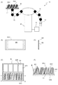
図1は、本実施形態に係る移送装置10の概要を示す図である。同図(A)は、移送装置10の概略図であり、同図(B)は物品XA1の平面図、同図(C)は物品XA1の側面図、同図(D)はバケットBの平面(上面)図、同図(E)は、同図(D)のX−X線の断面図である。
FIG. 1 is a diagram showing an outline of the
本発明の移送装置10は、図1(A)に示すように、バケット支持手段11と、把持手段12と、第1アーム13と、第2アーム14と、制御手段15などを備え、上流から搬送されるバケットBに収容される複数の物品XA1を一括して把持(保持)して取り出し、下流工程に移送する装置である。
As shown in FIG. 1A, the
バケット支持手段11は、上流工程から物品XA1を収容して搬送されるバケットBを所定の支持位置において支持(保持)するとともに、所定の解放位置において支持(保持)を解放する手段である。 The bucket support means 11 is a means for supporting (holding) the bucket B accommodating and transporting the article XA1 from the upstream process at a predetermined support position and releasing the support (holding) at a predetermined release position.
第1アーム13は、多軸ロボット(例えば、6軸ロボット)の一の多関節アームであり、バケット支持手段11を3次元的に移動自在に支持する。具体的には第1アーム13の一端にバケット支持手段11が同軸的に回転自在に支持され、第1アーム13の他端は、3次元的に回転自在となるように基台30に取り付けられている。つまり、第1アーム13は、バケット支持手段11を介して支持するバケットBを複数の姿勢に変化させることができる。
The
把持手段12は、バケットBの一の収容部50に収容された複数の物品XA1からなる物品群XA2を一括して把持(挟持)し、下流の工程に移送可能に構成されている。
The gripping means 12 is configured to collectively grip (hold) the article group XA2 composed of a plurality of articles XA1 accommodated in one accommodating
第2アーム14は、多軸ロボットの他の多関節アームであり、把持手段12を3次元的に移動自在に支持する。具体的には第2アーム14の一端に把持手段12が同軸的に回転自在に支持され、第2アーム14の他端は、3次元的に回転自在となるように基台30に取り付けられている。つまり、第2アーム14は、第1アーム13が支持するバケットBの収容部50内に把持手段12を挿入して物品群XA2を一括して把持して取り出すことができる。
The
制御手段15は、例えば、CPU、RAM、及びROMなどから構成され、第1アーム13および第2アーム14の動作を始めとして、移送装置10の各部の各種制御を統括的に制御する。CPUは、いわゆる中央演算処理装置であり、各種プログラムが実行されて各種機能を実現する。RAMは、CPUの作業領域として使用される。ROMは、CPUで実行される基本OSやプログラムを記憶する。
The control means 15 is composed of, for example, a CPU, a RAM, a ROM, and the like, and comprehensively controls various controls of each part of the
同図(B),同図(C)に示すように本実施形態の物品XA1は一例として、薄型、軽量で柔軟性も有するシート状であって個々に包装フィルムなどで包装された、例えば個包装のマスクである。 As shown in FIGS. (B) and (C), as an example, the article XA1 of the present embodiment is a thin, lightweight and flexible sheet, and is individually wrapped with a wrapping film or the like, for example, an individual. It is a mask for packaging.
また、同図(D),同図(E)に示すように、バケットBは例えば、升目状に区画された複数の収容部50を有する。そしてそれぞれの収容部50に、所定数(例えば、数枚〜数十枚など)の同一形状の物品XA1が、結束等されることなく個々に独立した状態で収容され、上流工程から搬送される。バケットB(各収容部50)は上面が開口された状態であり、各収容部50はそれぞれ、底面51と、底面51に略垂直な方向に立設された対向する2つの側面52A、52Bとを少なくとも有している。
Further, as shown in FIGS. (D) and (E), the bucket B has, for example, a plurality of
収容部50のそれぞれには、複数の物品XA1(物品群XA2)がそれぞれのシート面(袋面)SS(同図(B)、同図(C))を収容部50の底面51に対して起立するように厚み方向に並べた状態で収容されている。
In each of the
図2を参照してバケット支持手段11について説明する。同図はバケット支持手段11の一例を示す概要側面図である。同図(A)に示すように、バケット支持手段11は例えば、第1アーム13先端の軸AXに揺動可能に固定され、バケットBの底面を載置可能な載置部25と、バケットBと載置部25を固定(係合)可能な固定(係合)手段(不図示)を有する。
The bucket support means 11 will be described with reference to FIG. The figure is a schematic side view showing an example of the bucket support means 11. As shown in FIG. 3A, for example, the bucket support means 11 is swingably fixed to the shaft AX at the tip of the
バケット支持手段11は、上流から搬送されるバケットBを所定位置で載置部25に載置および固定する(同図(B))。第1アーム13は、バケット支持手段11を3次元的に移動自在に支持しており、これによりバケットBは複数の姿勢に変化可能となる。
The bucket support means 11 mounts and fixes the bucket B transported from the upstream on the mounting
本実施形態における「姿勢の変化」とは、バケットBが搬送されてバケット支持手段11にて支持された初期位置(例えば、同図(B)に示すように載置部25(バケットBの底面)を床面に水平な位置(以下、水平位置という。)で静止させた位置)から変化させることをいう。 The "change in posture" in the present embodiment means the initial position where the bucket B is conveyed and supported by the bucket supporting means 11 (for example, as shown in FIG. 3B), the mounting portion 25 (bottom surface of the bucket B). ) Is changed from a position horizontal to the floor (hereinafter referred to as a horizontal position).
具体的に例えば、同図(C)に示すように、載置部25(バケットBの底面)を水平位置から、バケットBの一辺(例えば図示の右辺)側が低く、他の一辺(例えば、図示の左辺)側が高くなるように傾斜させた姿勢に変化させることができる。 Specifically, for example, as shown in FIG. 6C, one side of the bucket B (for example, the right side in the drawing) is lower than the horizontal position of the mounting portion 25 (bottom surface of the bucket B), and the other side (for example, the drawing) is shown. It can be changed to an inclined posture so that the side (left side) is higher.
また、同図(D)に示すように、載置部25(バケットBの底面)を水平位置から、バケットBの一辺(例えば、図示の右辺)側が高く、他の一辺(例えば、図示の左辺)側が低くなるように傾斜させた姿勢に変化させることができる。 Further, as shown in FIG. 3D, the mounting portion 25 (bottom surface of the bucket B) is higher on one side (for example, the right side in the drawing) of the bucket B from the horizontal position, and the other side (for example, the left side in the drawing) is higher. ) Can be changed to an inclined posture so that the side is low.
つまり、バケットBを第1アーム13の軸AXを中心として揺動させることができる。
That is, the bucket B can be swung around the axis AX of the
また、第1アーム13の移動によって、同図(B)に示す水平位置において水平方向(図示左右方向)に往復移動等させることができ、この(バケットBが支持された初期位置から)往復移動した後の姿勢も姿勢の変化に含まれるものとする。
Further, by moving the
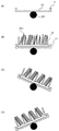
図3を参照して把持手段12について説明する。同図は、把持手段12の一例を示す概要図である。同図(A)、同図(C)〜同図(F)は、把持手段12をある一方から見た側面図であり、同図(B)は、把持手段12の下方の一部(第1把持部12A、第2把持部12Bの一部)を、同図(A)の左方向(右方向も同様)から見た側面図である。
The gripping means 12 will be described with reference to FIG. FIG. 6 is a schematic view showing an example of the gripping
把持手段12は、互いに近接・離間する第1把持部12Aと第2把持部12Bを有する。
The gripping means 12 has a
具体的に、同図(A)に示すように把持手段12は、第2アーム14の一端から続く連結部121を有し、連結部121の先端にブラケット122が設けられ、その一端に第1把持部12Aが固定されている。第1把持部12Aの形状は例えば、同図(A)、同図(B)に示すように、少なくとも一部が収容部50に挿入可能なサイズの板状体であり、一方の面(把持面12AS)に物品XA1のシート面(袋面)SSを当接させるようにして物品XA1を把持(保持)する。
Specifically, as shown in FIG. (A), the gripping
また、ブラケット122の他端には、サーボ制御などによって、ブラケット122に対して垂直方向(同図(C),矢印α参照)に移動可能なスライダー123と、ブラケット122に対して平行方向(同図(E),矢印β参照)に移動可能なスライダー124が設けられ、更にスライダー124には更にロータリアクチュエータ(例えば、空気圧ロータリアクチュエータ)125を介して第2把持部12Bが取り付けられている。ロータリーアクチュエータ125は、揺動軸126を中心として、第2把持部12Bの先端(下端)が第1把持部12Aに近接、離間するように揺動可能となっている(同図(F)、矢印γ参照)。第2把持部12Bの形状も、例えば第1把持部12Aと同様に収容部50に挿入可能なサイズの板状体であり(同図(A)、同図(B))、一方の面(把持面12BS)に物品XA1のシート面(袋面)SSを当接させるようにして物品XA1を把持(保持)する。
Further, at the other end of the
つまり把持手段12は、第1把持部12Aに対して、第2把持部12Bが相対的に移動可能に構成されている。具体的に、まず同図(A)、同図(C)に示すように、第1把持部12Aと第2把持部12Bが略平行且つ最大限に離間された状態で対向配置され、両者が収容部50の底面51に対して略垂直になっている状態を基準状態として説明する。
That is, the gripping
制御手段15は同図(D)に示すように、第2把持部12Bを、第2アーム14方向(図示上方)に近接するように把持面12BS方向にスライドさせて、基準状態に対して第1把持部12Aから離間させることができる。この場合の第2把持部12Bの状態を上方退避状態という。この上方退避状態にある第2把持部12Bは、第1把持部12Aの一部が収容部50に収容された場合、収容部50(バケットB)と干渉しない位置に退避している状態とする。
As shown in FIG. 3D, the control means 15 slides the
また制御手段15は、同図(E)に示すように、第1把持部12Aと対向させた状態で、対向する距離が小さくなるように、基準状態に対して第1把持部12Aに近接させることができる。この場合の第2把持部12Bの状態を近接状態という。
Further, as shown in FIG. 3E, the control means 15 is brought closer to the
次に、図4を参照して本実施形態の移送装置10の動作を説明する。同図は主に、移送装置10によって、バケットBから物品群XA2を把持して取り出す動作の部分を抜き出して示す概要図である。
Next, the operation of the
まず、同図(A)に示すように、制御手段15は、第1アーム13(図4において不図示、以下同様)が支持するバケット支持手段11を所定の支持位置で待機させ、上流工程から搬送されるバケットBを当該支持位置にて支持(保持、固定)する。バケットBの少なくとも1つの収容部50には、複数の物品XA1が結束等されない状態で収容されている。
First, as shown in FIG. 6A, the control means 15 makes the bucket support means 11 supported by the first arm 13 (not shown in FIG. 4, the same applies hereinafter) stand by at a predetermined support position, and starts from the upstream process. The conveyed bucket B is supported (held and fixed) at the support position. A plurality of articles XA1 are housed in at least one
次に、同図(B)に示すように制御手段15は、第1アーム13によってバケットBの姿勢を変化させて、収容部50内に第1把持部12Aの挿入領域20を創出する。より具体的には、第1アーム13によって、収容部50の底面51(バケットBの底部)が水平位置(同図(A)に示す位置)から傾斜する第1の姿勢となるようにバケットBを移動させる。この例では、同図(B)に示すように、収容部50の底面51の右端部が左端部より低くなるように底面51(バケットBの底部)を水平位置から傾斜させた第1の姿勢に変化させている。これにより、当該収容部50に収容されている複数の物品XA1はそれぞれに、収容部50の一方(同図右)側の側面52A側に偏り、当該収容部50の対向する他方(同図左)側の側面52Bと、物品XA1(物品群XA2)の間に、把持手段12の一部(物品XA1の把持に十分な第1把持部12Aの少なくとも一部)が挿入可能な空間(以下、「第1挿入領域20」という。)が創出される。
Next, as shown in FIG. 3B, the control means 15 changes the posture of the bucket B by the
なおこの場合の複数の物品XA1の偏りの程度は、搬送時(同図(A))の収容部50内の複数の物品XA1の状態(姿勢)や、姿勢を変化させるためのバケットBの移動の程度によって異なり、第1挿入領域20(空間)のサイズも異なる。
In this case, the degree of bias of the plurality of articles XA1 is the state (posture) of the plurality of articles XA1 in the
本実施形態では、第1アーム13は、例えば必要に応じて適宜バケットBを揺動するなどして、物品XA1の把持に十分な第1把持部12Aの少なくとも一部が挿入可能な第1挿入領域20が創出されるように、バケットBの姿勢を変化させる。
In the present embodiment, the
次に、同図(C)に示すように制御手段15は、第2アーム14(図4において不図示、以下同様)によって把持手段12をバケットBの上方に移動させ、第2把持部12Bを上方退避状態(図3(D))として、創出した第1挿入領域20に物品XA1の把持に十分な第1把持部12Aの少なくとも一部を挿入する。ここで、「物品XA1の把持に十分な第1把持部12Aの少なくとも一部」との記載は、バケットBの形状(深さ)によって、物品XA1を把持する状態においても第1把持部12Aの全てが収容部50に挿入されない場合があることを含む趣旨であり、第1把持部12Aは、物品XA1の種類や形状、バケットBの形状に応じて適宜、物品XA1が最も確実に把持できる位置に挿入されるものとする。従って、以下の説明において、「物品XA1の把持に十分な第1把持部12Aの少なくとも一部を挿入」を単に「第1挿入領域20に第1把持部12Aを挿入」と記載する場合もある。
Next, as shown in FIG. 4C, the control means 15 moves the gripping means 12 above the bucket B by the second arm 14 (not shown in FIG. 4, the same applies hereinafter) to move the second
同図(A)において各収容部50内の物品XA1の姿勢がばらついていた場合であっても、同図(B)または同図(C)のようにバケットBを第1の姿勢に変化させることで、側面52Aと重力によって物品XA1の少なくとも一部の姿勢が整えられる。
Even if the postures of the articles XA1 in each
なお、同図(C)において、第2アーム14によって把持手段12(第1把持部12A)を底面51と平行な方向に移動させ、物品XA1(物品群XA2)を側面52A側に寄せるようにしてもよい。これにより物品XA1の少なくとも一部の姿勢を整えることができる。
In FIG. 3C, the gripping means 12 (first gripping
その後、同図(D)に示すように、第1把持部12Aを収容部50に挿入した状態で、第1アーム13によってバケットBを、第1の姿勢とは異なる第2の姿勢に変化させる。具体的には、第1アーム13によって、収容部50の底面51(バケットBの底部)が水平位置となる方向に移動させ、例えば、収容部50の底面51の右端部が左端部より高くなるように底面51(バケットBの底部)を水平位置から傾斜させる。
After that, as shown in FIG. 3D, with the
これにより、収容部50に収容されている複数の物品XA1はそれぞれに、収容部50の他方(同図左)側の側面52B側に偏り、また、第1把持部12Aの一部の上方に物品群XA2の一部が重なって配置される。そして、当該収容部50の対向する一方(同図右)側の側面52Aと、物品群XA2の間に、物品XA1の把持に十分な第2把持部12Bの少なくとも一部が挿入可能な空間(以下、「第2挿入領域21」という。)が創出される。また複数の物品XA1は更にその姿勢が整えられる。
As a result, the plurality of articles XA1 accommodated in the
このように、本実施形態では複数の物品XA1(物品群XA2)を、その両側に位置する収容部50の側面52A,52Bに当接させるように、バケットBを異なる方向に傾斜させる(第1アーム13の軸AXを中心に揺動させる)ことにより、重力と側面52A,52Bによって複数の物品XA1の姿勢を整えることができる。
As described above, in the present embodiment, the bucket B is tilted in different directions so that the plurality of articles XA1 (article group XA2) are brought into contact with the side surfaces 52A and 52B of the
なおこの場合も複数の物品XA1の偏りの程度は、直前の収容部50内の複数の物品XA1の状態(姿勢)や、姿勢を変化させるためのバケットBの移動の程度によって異なり、第2挿入領域21(空間)のサイズも異なる。
In this case as well, the degree of bias of the plurality of articles XA1 differs depending on the state (posture) of the plurality of articles XA1 in the immediately preceding
第1アーム13は、物品XA1の把持に十分な第2把持部12Bの少なくとも一部が挿入可能な第2挿入領域21が創出されるように、バケットBの姿勢を変化させるものとする。従って例えば、バケットBを水平位置まで移動させた場合に第2挿入領域21が形成できればそれ以上は傾斜をさせなくてもよい。
The
次に、同図(E)に示すように制御手段15は、把持手段12の第2把持部12Bを基準状態(図3(A)、図3(C)))に移動させ、創出した第2挿入領域21に物品XA1の把持に十分な第2把持部12Bの少なくとも一部を挿入する。ここで、「物品XA1の把持に十分な第2把持部12Bの少なくとも一部」との記載も、バケットBの形状(深さ)によって、物品XA1を把持する状態においても第2把持部12Bの全てが収容部50に挿入されない場合があることを含む趣旨である。つまり、第2把持部12Bは、物品XA1の種類や形状、バケットBの形状に応じて適宜、物品XA1が最も確実に把持できる位置に挿入されるものとし、「第2挿入領域21に物品XA1の把持に十分な第2把持部12Bの少なくとも一部を挿入」を単に「第2挿入領域21に第2把持部12Bを挿入」と記載する場合もある。
Next, as shown in FIG. 3E, the control means 15 creates a
そして同図(F)に示すように、制御手段15は、第2把持部12Bを近接状態(図3(E))に移動する。これにより、複数の物品XA1は第1把持部12Aと第2把持部12Bに挟まれ、両者に倣って更にその姿勢が整えられる。
Then, as shown in FIG. 3F, the control means 15 moves the
そして同図(G)に示すように、制御手段15は、バケットBを水平位置に戻し、第2把持部12Bを先端近接状態(図3(F))に移動する。これにより、複数の物品XA1(物品群XA2)が確実に第1把持部12Aと第2把持部12Bに把持(挟持)される。
Then, as shown in FIG. 3G, the control means 15 returns the bucket B to the horizontal position and moves the
その後同図(H)に示すように、制御手段15は、第2アーム14によって把持手段12を収容部50から抜き出し、物品群XA2を一括して次工程に移送する。なお、同図(F)に示す近接状態とした後、バケットBを傾斜させたまま、第2把持部12Bを先端近接状態(図3(F))に移動して1把持部12Aと第2把持部12Bによって物品群XA2を挟持してもよいし、更にその挟持した状態で、斜め左上方に把持手段12を抜き出してもよい。
After that, as shown in FIG. (H), the control means 15 pulls out the gripping means 12 from the
このように本実施形態の移送装置10は、バケットBを3次元的に移動自在に支持する第1アーム13によってバケットのB姿勢を変化させて収容部50内に把持手段12(第1把持部12A)の第1挿入領域20を創出するステップと、把持手段12を3次元的に移動自在に支持する第2アーム14によって第1挿入領域20に該把持手段12の一部(第1把持部12A)を挿入するステップと、を実行する。
As described above, in the
より詳細には、移送装置10は、複数の物品XA1を、収容部50の対向する2つの側面52A52Bのうち一方の側面52B側に偏らせて他方の側面52Aと物品群XA2の間に第1挿入領域20を創出するステップと、第1挿入領域20に第1把持部12Aの少なくとも一部を挿入するステップと、第1把持部12Aの少なくとも一部に複数の物品XA1の少なくとも一部が重なるように複数の物品XA1を他方の側面52A側に偏らせて一方の側面52Bと物品群XA2の間に第2挿入領域21を創出するステップと、第2挿入領域21に第2把持部12Bの少なくとも一部を挿入し、第2把持部12Bと第1把持部12Aによって物品群XA2を把持するステップを実行する。これにより、バケットBの一の収容部50に収容された複数の物品XA1からなる物品群XA2を把持手段12により一括して取り出し、下流の工程に移送する。
More specifically, the
なお、本実施形態の物品群XA2の把持の態様は、上記の例に限らない。本実施形態では、第1アーム13によってバケットBの姿勢を変化(例えば、バケットBを揺動)させて第1挿入領域20を創出し、第2アーム14によって当該第1挿入領域20に第1把持部12Aを挿入した後、再び第1アーム13によってバケットBの姿勢を変化(例えば、バケットBを揺動)させて第2挿入領域21を創出し、当該第2挿入領域21に第2把持部12Bを挿入して物品群XA2を把持する構成であればよい。
The mode of gripping the article group XA2 of the present embodiment is not limited to the above example. In the present embodiment, the posture of the bucket B is changed by the first arm 13 (for example, the bucket B is swung) to create the
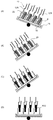
つまり、図5(A)、図4(D)に示すように、第2把持部12Bを上方退避状態から、図5(B)、図4(E)に示す基準状態に移動した後は、図5(C)に示すように先端近接状態とした後、図5(D)に示すように近接状態に移動して物品群XA2を把持してもよい。
That is, as shown in FIGS. 5 (A) and 4 (D), after the
また、図5(C)に示す先端近接状態で物品群XA2の把持が可能であれば、同図(D)に示す近接状態を経なくてもよい。 Further, if the article group XA2 can be gripped in the state of proximity to the tip shown in FIG. 5C, it is not necessary to go through the state of proximity shown in FIG. 5D.
さらに、把持手段12は、図5(E)および同図(F)に示すように、スライダー123、124を設けず、垂直方向および水平方向のスライドを行なわない構成であってもよい。この場合、第2把持部12Bは、ロータリーアクチュエータ125で揺動のみ(基準状態と先端近接状態の移動のみ)となり同図(F)に示す先端近接状態で物品群XA2を把持する。また、図示は省略するが、図5(E)同図(F)において、スライダー123、124のいずれか一方を設け、第2把持部12Bは、垂直方向および水平方向のスライドの何れか一方と、ロータリーアクチュエータ125による揺動を行なうように構成してもよい。
Further, as shown in FIGS. 5 (E) and 5 (F), the gripping
図6および図7は本実施形態のバケットBの姿勢の変化の他の例であり、上述の実施形態に適宜追加または入れ替えをしてもよい。 6 and 7 are other examples of changes in the posture of the bucket B of the present embodiment, and may be added or replaced as appropriate to the above-described embodiment.
図6(A)に示すように、第1アーム13は、例えば、上流工程から搬送されるバケットBを支持した直後、および/または第1把持部12Aと第2把持部12Bによる把持以前の適宜のタイミングで、同図(B)の矢印aで示すようにバケットBの底部の水平状態を維持したまま左右に移動させる工程、あるいは、矢印bで示すように、バケットBを軸AXを中心に揺動させる工程を行なってもよい。これにより、把持の動作に入る前に、物品XA1の姿勢をより整えることができ、さらに確実な把持が可能となる。
As shown in FIG. 6A, the
また、図7(A)に示すように、第2挿入領域21に第2把持部12Bを挿入した後に、収容部50の底面51(バケットの底部)が床面に対して略垂直となるように、バケットBを移動させてもよい。この場合第1把持部12Aと第2把持部12Bの間において複数の物品XA1はシート面(袋面)SSが略水平状態で積層されるため、同図(B)に示すように、その後の第1把持部12Aと第2把持部12Bによる把持を確実にできる場合がある。また、例えば、次工程において、物品XA1のシート面(袋面)SSを略水平状態で積層して受け入れるような場合にも好適である。
Further, as shown in FIG. 7A, after inserting the
なお、以上説明した実施形態では、バケットBの複数の収容部50に対して、順次、把持手段12を挿入して物品群XA2を把持する。つまり、図4に示す一連の動作を1回の取り出し動作とした場合、1つのバケットBが8個の収容部50を有していれば、8回の取り出し動作を行うと1つのバケットBの全ての物品XA1の取り出しが行なわれる。
In the embodiment described above, the gripping
この場合例えば、取り出し対象の1つめの収容部50内の物品XA1に比べて、2つめ以降の収容部50内の物品XA1は、取り出し動作が繰り返されるほど、姿勢が整えられる。つまり、2つめ以降の収容部50の取り出し動作は、図4に示す一連の動作を適宜簡略化してもよい。
In this case, for example, as compared with the article XA1 in the first
図8は、他の実施形態の一例を示す図である。移送装置10は、第2アーム14に複数の(例えば、4個)の把持手段12設けられる構成であってもよい。この場合の取り出し動作の一例を説明すると、バケットBを揺動させて第1挿入領域20を創出し、4個の第1把持部12Aを同時に挿入する(同図(A))。
FIG. 8 is a diagram showing an example of another embodiment. The
またバケットBの姿勢を変化(揺動)させて第2挿入領域21を創出し4個の第2把持部12Bを挿入し、第2把持部12Bを第1把持部12Aに近接させて(同図(C))、それぞれに物品群XA2を把持し、取り出す(同図(D))。
Further, the posture of the bucket B is changed (swinged) to create a
バケットBの姿勢の変化(揺動)によって、全ての収容部50内の物品XA1は同じように姿勢が整えられるため、例えば1列分(4個)の収容部50に対応した把持手段12を設けることで、これらを一括して取り出しすることができる。但し、この場合は第2アーム14の先端における重量が増加したり、また、バケットBの形状によって複数(4個)の把持手段12同士の位置の調整等が必要になる。
Since the postures of the articles XA1 in all the
以上、本実施形態によれば、薄く軽量で柔軟性もあるシート状物品が結束等されない状態で収容部に収容されている場合であっても、複数の物品XA1を纏めた状態で一括して確実に取り出し、次工程に移送することができる。 As described above, according to the present embodiment, even when thin, lightweight, and flexible sheet-shaped articles are housed in the storage section without being bound, a plurality of articles XA1 are collectively stored. It can be reliably taken out and transferred to the next process.
また複数種類の物品XA1(例えば、化粧品とマスクなど)に共用なバケットBを使用しているラインでは、収容部50は汎用的に設定されている場合がある。このような場合、物品群XA2に対して収容部50が大きく、物品XA1の姿勢がばらつき易い問題があるが、本実施形態によれば、当該収容部50の空間を利用して、バケットBの姿勢を変化させながら物品XA1の姿勢を整える。そして、第1挿入領域20を創出させて第1把持部12Aを挿入し、再びバケットBの姿勢を変化させて第2挿入領域21を創出させて第2把持部12Bを挿入し、物品群XA2を把持する。
Further, in a line in which a bucket B shared by a plurality of types of articles XA1 (for example, cosmetics and masks) is used, the
従って、バケットBが共用される場合であっても、確実な物品XA1の保持が可能となり、従来人手によっていた作業を自動化することができる。つまり人員の削減、および作業効率を向上させることができる。 Therefore, even when the bucket B is shared, the article XA1 can be reliably held, and the conventional manual work can be automated. That is, the number of personnel can be reduced and the work efficiency can be improved.
なお、バケット支持手段11は、バケットBを上述のとおり、複数の姿勢に変化可能に支持(保持)可能な手段であれば上述の例に限らず、例えば、バケットBの縁部(側面)などを把持あるいは吸着などすることにより支持する構成であってもよい。 The bucket supporting means 11 is not limited to the above example as long as it is a means capable of supporting (holding) the bucket B in a plurality of postures as described above, and for example, the edge portion (side surface) of the bucket B or the like. It may be supported by gripping or sucking.
また、制御手段15は、基準状態から第1把持部12Aとの対向する距離が大きくなるように、第2把持部12Bを第1把持部12Aから離間させたり、基準状態から第2把持部12Bの先端が第1把持部12Aの先端から離れるように後方に揺動させるように第2把持部12Bを移動可能としてもよい。
Further, the control means 15 separates the
以上、本発明に係る移送装置10は、上述の実施の形態に限らず、本発明の趣旨及び技術思想を逸脱しない範囲で種々の変形が可能である。
As described above, the
すなわち、上記実施形態において、各構成の位置、大きさ、長さ、形状、材質、向きなどは適宜変更できる。 That is, in the above embodiment, the position, size, length, shape, material, orientation, etc. of each configuration can be appropriately changed.
10 移送装置
11 バケット支持手段
12 把持手段
12A 第1把持部
12B 第2把持部
13 第1アーム
14 第2アーム
15 制御手段
20 第1挿入領域
21 第2挿入領域
50 収容部
51 底面
52A,52B 側面
10
Claims (11)
前記物品群を一括して把持可能な把持手段と、
バケットを支持可能なバケット支持手段と、
前記バケット支持手段を3次元的に移動自在に支持する第1のアームと、
前記把持手段を3次元的に移動自在に支持する第2のアームと、
前記第1のアームおよび前記第2のアームを制御可能な制御手段と、を備え、
前記制御手段は、前記第1のアームによって前記バケットの姿勢を変化させて前記収容部内に前記把持手段の挿入領域を創出し、前記第2のアームによって前記挿入領域に前記把持手段の一部を挿入する、
ことを特徴とする移送装置。 A transfer device that collectively takes out a group of articles composed of a plurality of articles housed in one storage part of a bucket and transfers them to a downstream process.
A gripping means capable of collectively gripping the article group and
Bucket support means that can support the bucket,
A first arm that supports the bucket support means three-dimensionally so as to be movable, and
A second arm that supports the gripping means in a three-dimensional manner and
A control means capable of controlling the first arm and the second arm is provided.
The control means changes the posture of the bucket by the first arm to create an insertion region of the gripping means in the accommodating portion, and a part of the gripping means is inserted into the insertion region by the second arm. insert,
A transfer device characterized by that.
前記把持手段は、第1の把持部と第2の把持部を有し、
前記制御手段は、
前記複数の物品を一方の前記側面側に偏らせて他方の前記側面と前記物品群の間に前記挿入領域を創出するように前記第1のアームによって前記バケットを第1の姿勢に変化させ、
前記第2のアームによって前記挿入領域に前記第1の把持部の少なくとも一部を挿入する、
ことを特徴とする請求項1に記載の移送装置。 The accommodating portion is a box-shaped body having two opposite sides.
The gripping means has a first gripping portion and a second gripping portion.
The control means
The bucket is changed to the first posture by the first arm so as to bias the plurality of articles toward one side surface and create the insertion region between the other side surface and the article group.
At least a part of the first grip is inserted into the insertion region by the second arm.
The transfer device according to claim 1.
前記複数の物品を他方の前記側面側に偏らせて一方の前記側面と前記物品群の間に他の挿入領域を創出するように前記第1のアームによって前記バケットを第2の姿勢に変化させ、
前記第2のアームによって前記他の挿入領域に前記第2の把持部の少なくとも一部を挿入し、該第2の把持部と前記第1の把持部によって前記物品群を把持する、
ことを特徴とする請求項2に記載の移送装置。 The control means
The bucket is changed to a second posture by the first arm so as to bias the plurality of articles toward the other side surface side and create another insertion region between the one side surface and the article group. ,
At least a part of the second grip portion is inserted into the other insertion region by the second arm, and the article group is gripped by the second grip portion and the first grip portion.
2. The transfer device according to claim 2.
前記第1の把持部の少なくとも一部に前記複数の物品の少なくとも一部が重なるように前記姿勢を変化させる、
ことを特徴とする請求項3に記載の移送装置。 The control means
The posture is changed so that at least a part of the plurality of articles overlaps at least a part of the first grip portion.
The transfer device according to claim 3, wherein the transfer device is characterized by the above.
ことを特徴とする請求項1乃至請求項4のいずれかに記載の移送装置。 The article is a lightweight object having a thin outer shape.
The transfer device according to any one of claims 1 to 4, wherein the transfer device is characterized in that.
バケットを支持可能なバケット支持手段と、
前記バケット支持手段を支持する第1のアームと、
前記把持手段を支持する第2のアームと、
前記第1のアームおよび前記第2のアームを制御可能な制御手段と、を備え、
前記バケットを複数の姿勢に変化させるとともに、前記収容部内に前記把持手段を挿入して前記物品群を一括して把持して取り出し、下流の工程に移送する、
ことを特徴とする移送装置。 A gripping means capable of collectively gripping a group of articles composed of a plurality of articles housed in one storage portion of a bucket.
Bucket support means that can support the bucket,
A first arm that supports the bucket support means,
A second arm that supports the gripping means and
A control means capable of controlling the first arm and the second arm is provided.
While changing the bucket into a plurality of postures, the gripping means is inserted into the accommodating portion to collectively grip and take out the article group, and the bucket is transferred to a downstream process.
A transfer device characterized by that.
前記バケットを3次元的に移動自在に支持する第1のアームによって該バケットの姿勢を変化させて前記収容部内に前記把持手段の挿入領域を創出するステップと、
前記把持手段を3次元的に移動自在に支持する第2のアームによって前記挿入領域に該把持手段の一部を挿入するステップと、を有する、
ことを特徴とする移送方法。 A transfer method in which a group of articles composed of a plurality of articles housed in one storage portion of a bucket is collectively taken out by a gripping means and transferred to a downstream process.
A step of changing the posture of the bucket by a first arm that movably supports the bucket in three dimensions to create an insertion region of the gripping means in the accommodating portion.
It has a step of inserting a part of the gripping means into the insertion region by a second arm that movably supports the gripping means in three dimensions.
A transfer method characterized by that.
前記前記挿入領域に前記把持手段の一方の把持部の少なくとも一部を挿入するステップと、を有する、
ことを特徴とする請求項7に記載の移送方法。 A step of biasing the plurality of articles toward one of the two opposing sides of the accommodating portion to the side of the side to create the insertion region between the other side and the group of articles.
It has a step of inserting at least a part of one grip portion of the grip means into the insertion region.
7. The transfer method according to claim 7.
前記他の挿入領域に前記把持手段の他方の把持部の少なくとも一部を挿入し、該他の把持部と前記把持部によって前記物品群を把持する、
ことを特徴とする請求項8に記載の移送方法。 A step of biasing the plurality of articles toward the other side surface side to create another insertion region between the one side surface and the article group.
At least a part of the other grip portion of the grip means is inserted into the other insertion region, and the article group is gripped by the other grip portion and the grip portion.
8. The transfer method according to claim 8.
ことを特徴とする請求項9に記載の移送方法。 The posture is changed so that at least a part of the plurality of articles overlaps at least a part of the grip portion to create the other insertion region.
9. The transfer method according to claim 9.
バケットを支持可能なバケット支持手段と、
前記バケット支持手段を支持する第1のアームと、
前記把持手段を支持する第2のアームと、
前記第1のアームおよび前記第2のアームを制御可能な制御手段と、を備える移送装置における移送方法であって、
前記バケットを複数の姿勢を変化させるとともに、前記収容部内に前記把持手段を挿入して前記物品群を一括して把持して取り出し、下流の工程に移送する、
ことを特徴とする移送方法。 A gripping means capable of collectively gripping a group of articles composed of a plurality of articles housed in one storage portion of a bucket.
Bucket support means that can support the bucket,
A first arm that supports the bucket support means,
A second arm that supports the gripping means and
A transfer method in a transfer device including a control means capable of controlling the first arm and the second arm.
While changing a plurality of postures of the bucket, the gripping means is inserted into the accommodating portion to collectively grip and take out the article group, and the bucket is transferred to a downstream process.
A transfer method characterized by that.
Priority Applications (1)
| Application Number | Priority Date | Filing Date | Title |
|---|---|---|---|
| JP2019108331A JP7349700B2 (en) | 2019-06-11 | 2019-06-11 | Transfer device and method |
Applications Claiming Priority (1)
| Application Number | Priority Date | Filing Date | Title |
|---|---|---|---|
| JP2019108331A JP7349700B2 (en) | 2019-06-11 | 2019-06-11 | Transfer device and method |
Publications (2)
| Publication Number | Publication Date |
|---|---|
| JP2020200080A true JP2020200080A (en) | 2020-12-17 |
| JP7349700B2 JP7349700B2 (en) | 2023-09-25 |
Family
ID=73742365
Family Applications (1)
| Application Number | Title | Priority Date | Filing Date |
|---|---|---|---|
| JP2019108331A Active JP7349700B2 (en) | 2019-06-11 | 2019-06-11 | Transfer device and method |
Country Status (1)
| Country | Link |
|---|---|
| JP (1) | JP7349700B2 (en) |
Cited By (1)
| Publication number | Priority date | Publication date | Assignee | Title |
|---|---|---|---|---|
| JP2022160713A (en) * | 2021-04-07 | 2022-10-20 | 株式会社日清製粉グループ本社 | Pickup device and pickup method |
Citations (5)
| Publication number | Priority date | Publication date | Assignee | Title |
|---|---|---|---|---|
| EP0528772A1 (en) * | 1991-07-26 | 1993-02-24 | MARCHESINI GROUP S.p.A. | Process and apparatus for automatically feeding a conveyor with carton blanks taken directly from bowl containers |
| JP2002308238A (en) * | 2001-04-11 | 2002-10-23 | Aruemu:Kk | Article take-out device |
| US20030120387A1 (en) * | 2001-12-20 | 2003-06-26 | Abb Automation Inc. | End effector for transferring articles |
| DE202012000940U1 (en) * | 2012-01-28 | 2012-03-23 | Thomas Goldfuß | Swivel unit: Synchronous swiveling with gripping unit |
| JP2019064592A (en) * | 2017-09-28 | 2019-04-25 | 大森機械工業株式会社 | Box filling device and box filling method |
-
2019
- 2019-06-11 JP JP2019108331A patent/JP7349700B2/en active Active
Patent Citations (5)
| Publication number | Priority date | Publication date | Assignee | Title |
|---|---|---|---|---|
| EP0528772A1 (en) * | 1991-07-26 | 1993-02-24 | MARCHESINI GROUP S.p.A. | Process and apparatus for automatically feeding a conveyor with carton blanks taken directly from bowl containers |
| JP2002308238A (en) * | 2001-04-11 | 2002-10-23 | Aruemu:Kk | Article take-out device |
| US20030120387A1 (en) * | 2001-12-20 | 2003-06-26 | Abb Automation Inc. | End effector for transferring articles |
| DE202012000940U1 (en) * | 2012-01-28 | 2012-03-23 | Thomas Goldfuß | Swivel unit: Synchronous swiveling with gripping unit |
| JP2019064592A (en) * | 2017-09-28 | 2019-04-25 | 大森機械工業株式会社 | Box filling device and box filling method |
Cited By (2)
| Publication number | Priority date | Publication date | Assignee | Title |
|---|---|---|---|---|
| JP2022160713A (en) * | 2021-04-07 | 2022-10-20 | 株式会社日清製粉グループ本社 | Pickup device and pickup method |
| JP7591456B2 (en) | 2021-04-07 | 2024-11-28 | 株式会社日清製粉グループ本社 | Pick-up device and pick-up method |
Also Published As
| Publication number | Publication date |
|---|---|
| JP7349700B2 (en) | 2023-09-25 |
Similar Documents
| Publication | Publication Date | Title |
|---|---|---|
| CN104302549B (en) | Method and apparatus for placing packages into cartons | |
| CN205675479U (en) | For carrying the structure of article, part goods or bundle | |
| TWI672250B (en) | Food holding device and operating method thereof | |
| US7717255B2 (en) | End of arm tool, apparatus, and method of engaging an article | |
| TWI651243B (en) | Transport system and its operation method | |
| JP7050742B2 (en) | Gripping devices, road stations, and methods for gripping stacks | |
| US20160039550A1 (en) | Apparatus and method for grouping and positioning items | |
| CN103764352A (en) | Robot, handling system and method for creating article-containing container | |
| JP2017218268A (en) | Food stuffing equipment | |
| JP2014094775A (en) | Sandwich packing apparatus | |
| CN110799435A (en) | Method and device for handling piece goods, goods and/or multi-piece goods | |
| CN1918054B (en) | Method and device for handling rod-shaped objects | |
| JP6496791B2 (en) | Food transport equipment | |
| JP6041310B2 (en) | Food gripping device and container packing device | |
| JP2018122906A (en) | Assembly apparatus and assembly method | |
| JP7349700B2 (en) | Transfer device and method | |
| JP6379012B2 (en) | Goods transfer device | |
| JP5756393B2 (en) | Article conveying method and article conveying apparatus | |
| JPWO2019054252A1 (en) | Transfer device | |
| JP4907572B2 (en) | Article storing method and article storing device in container | |
| JP5859482B2 (en) | Horizontal bag making and filling machine | |
| WO2019049773A1 (en) | Transfer device | |
| JP6796121B2 (en) | Food transport mechanism and robot | |
| JP6980274B2 (en) | Goods supply device in packaging machine | |
| US11981023B2 (en) | Tote handling system with integrated hand and method of using same |
Legal Events
| Date | Code | Title | Description |
|---|---|---|---|
| A621 | Written request for application examination |
Free format text: JAPANESE INTERMEDIATE CODE: A621 Effective date: 20220609 |
|
| A131 | Notification of reasons for refusal |
Free format text: JAPANESE INTERMEDIATE CODE: A131 Effective date: 20230322 |
|
| A521 | Request for written amendment filed |
Free format text: JAPANESE INTERMEDIATE CODE: A523 Effective date: 20230519 |
|
| A131 | Notification of reasons for refusal |
Free format text: JAPANESE INTERMEDIATE CODE: A131 Effective date: 20230606 |
|
| A521 | Request for written amendment filed |
Free format text: JAPANESE INTERMEDIATE CODE: A523 Effective date: 20230727 |
|
| TRDD | Decision of grant or rejection written | ||
| A01 | Written decision to grant a patent or to grant a registration (utility model) |
Free format text: JAPANESE INTERMEDIATE CODE: A01 Effective date: 20230829 |
|
| A61 | First payment of annual fees (during grant procedure) |
Free format text: JAPANESE INTERMEDIATE CODE: A61 Effective date: 20230905 |
|
| R150 | Certificate of patent or registration of utility model |
Ref document number: 7349700 Country of ref document: JP Free format text: JAPANESE INTERMEDIATE CODE: R150 |