JP2020200091A - Packaging container - Google Patents

Packaging container Download PDF

Info

Publication number
JP2020200091A
JP2020200091A JP2019109434A JP2019109434A JP2020200091A JP 2020200091 A JP2020200091 A JP 2020200091A JP 2019109434 A JP2019109434 A JP 2019109434A JP 2019109434 A JP2019109434 A JP 2019109434A JP 2020200091 A JP2020200091 A JP 2020200091A
Authority
JP
Japan
Prior art keywords
packaging container
main body
connection side
lid
side portion
Prior art date
Legal status (The legal status is an assumption and is not a legal conclusion. Google has not performed a legal analysis and makes no representation as to the accuracy of the status listed.)
Granted
Application number
JP2019109434A
Other languages
Japanese (ja)
Other versions
JP7250328B2 (en
Inventor
和馬 込山
Kazuma Komiyama
和馬 込山
泰爾 小林
Yasuji Kobayashi
泰爾 小林
Current Assignee (The listed assignees may be inaccurate. Google has not performed a legal analysis and makes no representation or warranty as to the accuracy of the list.)
CP Chemicals Inc
Original Assignee
CP Chemicals Inc
Priority date (The priority date is an assumption and is not a legal conclusion. Google has not performed a legal analysis and makes no representation as to the accuracy of the date listed.)
Filing date
Publication date
Application filed by CP Chemicals Inc filed Critical CP Chemicals Inc
Priority to JP2019109434A priority Critical patent/JP7250328B2/en
Publication of JP2020200091A publication Critical patent/JP2020200091A/en
Application granted granted Critical
Publication of JP7250328B2 publication Critical patent/JP7250328B2/en
Active legal-status Critical Current
Anticipated expiration legal-status Critical

Links

Images

Landscapes

  • Containers Having Bodies Formed In One Piece (AREA)
  • Closures For Containers (AREA)

Abstract

【課題】被収容物を収容した状態での見栄えが良好であるとともに陳列効率にも優れた包装用容器を実現する。【解決手段】容器本体2は、底面部21と、底面部21から上方に延びる本体周壁部23と、本体周壁部23から外側に延びる本体フランジ部24と、を有し、本体フランジ部24は、容器本体2が接地している状態で傾斜するように形成されているとともに、周方向に離間して配置された最高高さ部位24Uおよび最低高さ部位24Lと、最高高さ部位24Uと最低高さ部位24Lとを周方向の一方側で接続する第一接続辺部241と、最高高さ部位24Uと最低高さ部位24Uとを周方向の他方側で接続する第二接続辺部242と、を有し、第一接続辺部241と第二接続辺部242とが、最低高さ部位24Lから互いに非対称態様で斜め上方に向けて傾斜している。【選択図】図5PROBLEM TO BE SOLVED: To realize a packaging container having a good appearance in a state of accommodating an object to be contained and also having excellent display efficiency. SOLUTION: A container main body 2 has a bottom surface portion 21, a main body peripheral wall portion 23 extending upward from the bottom surface portion 21, and a main body flange portion 24 extending outward from the main body peripheral wall portion 23, and the main body flange portion 24 has. , The maximum height portion 24U and the minimum height portion 24L, and the maximum height portion 24U and the minimum are arranged so as to be inclined while the container body 2 is in contact with the ground. A first connection side portion 241 that connects the height portion 24L on one side in the circumferential direction, and a second connection side portion 242 that connects the maximum height portion 24U and the minimum height portion 24U on the other side in the circumferential direction. , And the first connection side portion 241 and the second connection side portion 242 are inclined obliquely upward from the minimum height portion 24L in an asymmetric manner with respect to each other. [Selection diagram] Fig. 5

Description

本発明は、包装用容器に関する。 The present invention relates to a packaging container.

例えばスーパーやコンビニエンスストア等の各種店舗において、包装用容器に収容された状態で弁当や惣菜等の食品が販売されている。包装用容器に収容されて販売される食品において、その彩りやボリューム感等の見栄えは、価格と共に、消費者の購買意欲に結び付き得る非常に重要な要素となっている。この点、中に収容された食品の視認性を良好なものとすることを意図した包装用容器が、例えば特開2004−244116号公報(特許文献1)に開示されている。 For example, in various stores such as supermarkets and convenience stores, foods such as bento boxes and prepared foods are sold in a packaging container. In foods sold in packaging containers, the appearance such as color and volume is a very important factor that can be linked to consumers' purchasing motivation as well as price. In this regard, a packaging container intended to improve the visibility of the food contained therein is disclosed in, for example, Japanese Patent Application Laid-Open No. 2004-244116 (Patent Document 1).

この特許文献1の包装用容器は、蓋体20が、フラットな上面21と、この上面21の1/4程度の幅に形成された傾斜面22とを備えている。ラベルLを貼付する傾斜面22を上面21の1/4程度の幅とすることで、購買者は、蓋体20の大部分を占めてフラットな上面21の中央から中の食品を視認しやすくなっている。 The packaging container of Patent Document 1 includes a lid 20 having a flat upper surface 21 and an inclined surface 22 formed to have a width of about 1/4 of the upper surface 21. By making the inclined surface 22 to which the label L is affixed about 1/4 of the width of the upper surface 21, the purchaser can easily see the food inside from the center of the flat upper surface 21 which occupies most of the lid 20. It has become.

しかし、特許文献1の包装用容器は、全体が扁平な形状であり、縦横に並べて陳列する際に多くのスペースを必要とするという欠点があった。特に近年は、限りあるスペースにできるだけ多くの商品を陳列したいという要望が強いことも多く、そのような要望に応えられるものとはなっていなかった。 However, the packaging container of Patent Document 1 has a drawback that it has a flat shape as a whole and requires a lot of space when it is displayed vertically and horizontally. Especially in recent years, there have been many requests to display as many products as possible in a limited space, and such requests have not been met.

特開2004−244116号公報Japanese Unexamined Patent Publication No. 2004-244116

被収容物を収容した状態での見栄えが良好であるとともに陳列効率にも優れた包装用容器の実現が望まれる。 It is desired to realize a packaging container that looks good in a state where the contents to be contained are contained and has excellent display efficiency.

本発明に係る包装用容器は、
容器本体を備えた包装用容器であって、
前記容器本体は、底面部と、前記底面部から上方に延びる本体周壁部と、前記本体周壁部から外側に延びる本体フランジ部と、を有し、
前記本体フランジ部は、前記容器本体が接地している状態で傾斜するように形成されているとともに、周方向に離間して配置された最高高さ部位および最低高さ部位と、前記最高高さ部位と前記最低高さ部位とを周方向の一方側で接続する第一接続辺部と、前記最高高さ部位と前記最低高さ部位とを周方向の他方側で接続する第二接続辺部と、を有し、
前記第一接続辺部と前記第二接続辺部とが、前記最低高さ部位から互いに非対称態様で斜め上方に向けて傾斜している。
The packaging container according to the present invention
A packaging container with a container body
The container main body has a bottom surface portion, a main body peripheral wall portion extending upward from the bottom surface portion, and a main body flange portion extending outward from the main body peripheral wall portion.
The main body flange portion is formed so as to be inclined while the container main body is in contact with the ground, and the maximum height portion and the minimum height portion arranged apart from each other in the circumferential direction, and the maximum height portion. A first connection side portion that connects the portion and the minimum height portion on one side in the circumferential direction, and a second connection side portion that connects the maximum height portion and the minimum height portion on the other side in the circumferential direction. And have
The first connection side portion and the second connection side portion are inclined obliquely upward from the minimum height portion in an asymmetrical manner.

この構成によれば、本体フランジ部の第一接続辺部および第二接続辺部が、斜め上方に向けて傾斜しているため、本体フランジ部の最高高さ部位側に向かうに従い、本体周壁部の高さが高くなって収容能力を高く見せることができる。そのため、被収容物を収容した状態でのボリューム感を高めることができる。さらに、このような第一接続辺部および第二接続辺部が互いに非対称態様であることから、対称である場合に比べて独特の美観を創出することができる。従って、このような包装用容器によれば、見栄えを向上させることが可能となる。また、本構成の包装用容器を複数陳列する場合には、本体フランジ部における周方向の各部分に対して、その上方または下方に、他の包装用容器の本体フランジ部を配置することができる。従って、複数の包装用容器を部分的に重ねて陳列することができ、陳列効率を向上させることが可能となる。 According to this configuration, since the first connection side portion and the second connection side portion of the main body flange portion are inclined diagonally upward, the main body peripheral wall portion portion is directed toward the maximum height portion side of the main body flange portion. The height of the can be increased to make the capacity look higher. Therefore, it is possible to enhance the voluminous feeling in the state where the contained object is accommodated. Further, since the first connection side portion and the second connection side portion are asymmetrical with each other, it is possible to create a unique aesthetic appearance as compared with the case where the first connection side portion and the second connection side portion are symmetrical with each other. Therefore, according to such a packaging container, it is possible to improve the appearance. Further, when a plurality of packaging containers having this configuration are displayed, the main body flange portions of other packaging containers can be arranged above or below each portion of the main body flange portion in the circumferential direction. .. Therefore, a plurality of packaging containers can be partially stacked and displayed, and the display efficiency can be improved.

以下、本発明の好適な態様について説明する。但し、以下に記載する好適な態様例によって、本発明の範囲が限定される訳ではない。 Hereinafter, preferred embodiments of the present invention will be described. However, the scope of the present invention is not limited by the preferred embodiments described below.

一態様として、
前記第一接続辺部および前記第二接続辺部のそれぞれが、前記最低高さ部位から前記最高高さ部位に向けて漸次傾斜していることが好ましい。
As one aspect
It is preferable that each of the first connection side portion and the second connection side portion is gradually inclined from the minimum height portion toward the maximum height portion.

この構成によれば、複数の包装容器を部分的に重ねて陳列する場合に、規則的に並べて配置し易い。 According to this configuration, when a plurality of packaging containers are partially stacked and displayed, it is easy to arrange them regularly.

一態様として、
前記第一接続辺部と前記第二接続辺部とが、前記最低高さ部位からのそれぞれに沿った離間長さが等しい位置どうしを比較した場合に互いに異なる高さとなるように傾斜していることが好ましい。
As one aspect
The first connection side portion and the second connection side portion are inclined so as to have different heights when comparing positions having the same separation length along the minimum height portion. Is preferable.

この構成によれば、複数の包装用容器を部分的に重ねて陳列する場合に、基準となる包装用容器(基準包装用容器)を他の包装用容器の第一接続辺部に重ね合せる場合と他の包装用容器の第二接続辺部に重ね合せる場合とで、基準包装用容器における他の包装用容器に重ね合せる重ね合せ部分を、当該基準包装用容器における異なる箇所に設定することができる。従って、陳列態様の自由度が増し、陳列効率をさらに向上させることが可能となる。 According to this configuration, when a plurality of packaging containers are partially overlapped and displayed, a reference packaging container (standard packaging container) is overlapped with the first connection side portion of another packaging container. And when overlapping with the second connection side of another packaging container, the overlapping portion to be overlapped with the other packaging container in the standard packaging container can be set at different locations in the standard packaging container. it can. Therefore, the degree of freedom in the display mode is increased, and the display efficiency can be further improved.

一態様として、
前記最高高さ部位と前記最低高さ部位とが、前記本体フランジ部における周方向の最も離れた位置に離間して配置されていることが好ましい。
As one aspect
It is preferable that the maximum height portion and the minimum height portion are arranged apart from each other at the farthest positions in the circumferential direction of the main body flange portion.

この構成によれば、最高高さ部位と最低高さ部位とをそれぞれ周方向において接続する第一接続辺部と第二接続辺部とを、同程度の周方向領域を有するように設定することができる。従って、第一接続辺部および第二接続辺部のそれぞれに対して他の包装用容器を重ね合せるようにして複数の包装用容器を陳列する場合に、当該複数の包装用容器を規則的に並べて配置し易い。 According to this configuration, the first connection side portion and the second connection side portion that connect the maximum height portion and the minimum height portion in the circumferential direction are set so as to have the same degree of circumferential region. Can be done. Therefore, when displaying a plurality of packaging containers by superimposing another packaging container on each of the first connection side portion and the second connection side portion, the plurality of packaging containers are regularly displayed. Easy to place side by side.

一態様として、
前記本体フランジ部の全体が略平坦状に形成されていることが好ましい。
As one aspect
It is preferable that the entire main body flange portion is formed in a substantially flat shape.

この構成によれば、本体フランジ部を傾斜構造としつつも、その構成を簡略化することができる。また例えば、包装用容器が、容器本体の本体フランジ部に嵌合する蓋体を備える場合には、本体フランジ部と蓋体との嵌合部分の構成を簡略化し易い。 According to this configuration, the main body flange portion has an inclined structure, but the configuration can be simplified. Further, for example, when the packaging container includes a lid that fits into the main body flange of the container body, it is easy to simplify the configuration of the fitting portion between the main body flange and the lid.

一態様として、
基準包装用容器の前記第一接続辺部が、第1の方向において前記基準包装用容器に隣接する他の包装用容器である第1隣接包装用容器の前記第二接続辺部の上方に位置し、かつ、第2の方向において前記基準包装用容器に隣接する他の包装用容器である第2隣接包装用容器の前記第二接続辺部の下方に位置するように陳列可能であることが好ましい。
As one aspect
The first connecting side portion of the standard packaging container is located above the second connecting side portion of the first adjacent packaging container which is another packaging container adjacent to the standard packaging container in the first direction. However, it can be displayed so as to be located below the second connecting side portion of the second adjacent packaging container, which is another packaging container adjacent to the standard packaging container in the second direction. preferable.

この構成によれば、基準包装用容器と第1隣接包装用容器とを第1の方向において重ね合せることができると共に、基準包装用容器と第2隣接包装用容器とを第2の方向において重ね合せることができる。従って、複数の包装用容器を第1の方向と第2の方向とに並べて陳列する際、第1の方向及び第2の方向における陳列効率を向上させることができる。 According to this configuration, the standard packaging container and the first adjacent packaging container can be overlapped in the first direction, and the standard packaging container and the second adjacent packaging container can be overlapped in the second direction. Can be combined. Therefore, when a plurality of packaging containers are displayed side by side in the first direction and the second direction, the display efficiency in the first direction and the second direction can be improved.

一態様として、
前記容器本体に嵌合される蓋体をさらに備え、
前記蓋体は、天面部と、前記天面部から下方に延びる蓋体周壁部と、前記蓋体周壁部から外側に延びて前記本体フランジ部に重ね合される蓋体フランジ部と、を有し、
前記蓋体フランジ部は、前記本体フランジ部に対応して傾斜するように形成され、
基準包装用容器の前記第一接続辺部を、第1の方向において前記基準包装用容器に隣接する他の包装用容器である第1隣接包装用容器の前記蓋体周壁部に対して水平方向に当接させる際、前記第1隣接包装用容器の前記第二接続辺部が、前記基準包装用容器の前記本体周壁部には当接することなく前記基準包装用容器の前記第一接続辺部の下方に位置するように配置されることが好ましい。
As one aspect
Further provided with a lid to be fitted to the container body,
The lid has a top surface portion, a lid peripheral wall portion extending downward from the top surface portion, and a lid flange portion extending outward from the lid peripheral wall portion and superposed on the main body flange portion. ,
The lid flange portion is formed so as to be inclined corresponding to the main body flange portion.
The first connection side portion of the reference packaging container is oriented horizontally with respect to the lid peripheral wall portion of the first adjacent packaging container which is another packaging container adjacent to the reference packaging container in the first direction. The second connection side portion of the first adjacent packaging container does not abut on the peripheral wall portion of the main body of the reference packaging container, and the first connection side portion of the reference packaging container does not abut. It is preferably arranged so as to be located below.

この構成によれば、容器本体と蓋体とを備える包装用容器を第1の方向に並べて複数陳列する場合に、第1の方向に並ぶ複数の包装用容器を互いに位置決めしつつ、第1の方向における陳列効率を向上させることができる。 According to this configuration, when a plurality of packaging containers having a container body and a lid are arranged side by side in the first direction and a plurality of packaging containers are displayed, the first method is performed while positioning the plurality of packaging containers arranged in the first direction with each other. The display efficiency in the direction can be improved.

一態様として、
第2の方向において前記基準包装用容器に隣接する他の包装用容器である第2隣接包装用容器の前記第二接続辺部を、前記基準包装用容器の前記蓋体周壁部に対して水平方向に当接させる際、前記基準包装用容器の前記第一接続辺部が、前記第2隣接包装用容器の前記本体周壁部には当接することなく前記第2隣接包装用容器の前記第二接続辺部の下方に位置するようにことが好ましい。
As one aspect
The second connecting side portion of the second adjacent packaging container, which is another packaging container adjacent to the reference packaging container in the second direction, is horizontal to the lid peripheral wall portion of the standard packaging container. When abutting in the direction, the first connecting side portion of the reference packaging container does not abut on the peripheral wall portion of the main body of the second adjacent packaging container, and the second of the second adjacent packaging container. It is preferably located below the connecting side.

この構成によれば、容器本体と蓋体とを備える包装用容器を、第1の方向に加えて第2の方向にも並べて複数陳列する場合に、第2の方向に並ぶ複数の包装用容器を互いに位置決めしつつ、第2の方向における陳列効率を向上させることができる。 According to this configuration, when a plurality of packaging containers including a container body and a lid are arranged side by side in the second direction in addition to the first direction, a plurality of packaging containers arranged in the second direction are arranged. Can be positioned with each other while improving display efficiency in the second direction.

本発明のさらなる特徴と利点は、図面を参照して記述する以下の例示的かつ非限定的な実施形態の説明によってより明確になるであろう。 Further features and advantages of the present invention will be further clarified by the following illustration of exemplary and non-limiting embodiments described with reference to the drawings.

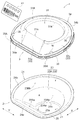
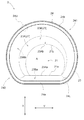
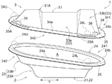
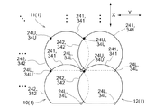
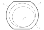
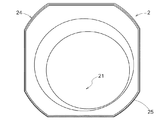
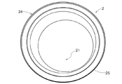
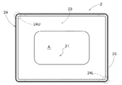
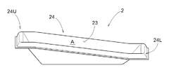
包装用容器の分解斜視図An exploded perspective view of the packaging container 容器本体の平面図Top view of the container body 蓋体の平面図Top view of the lid 包装用容器の分解側面図Disassembled side view of the packaging container 包装用容器の分解正面図Disassembled front view of the packaging container 複数の包装用容器が第1の方向および第2の方向に陳列された様子を示す図The figure which shows the appearance that a plurality of packaging containers were displayed in the 1st direction and the 2nd direction. 複数の包装用容器が第1の方向および第2の方向に陳列された様子を模式的に示す平面図Top view schematically showing how a plurality of packaging containers are displayed in the first direction and the second direction. 第1の方向に陳列された複数の包装用容器の断面図Sectional view of a plurality of packaging containers displayed in the first direction 第2の方向に陳列された複数の包装用容器の断面図Sectional view of a plurality of packaging containers displayed in the second direction その他の実施形態に係る容器本体の平面図Top view of the container body according to other embodiments その他の実施形態に係る容器本体の平面図Top view of the container body according to other embodiments その他の実施形態に係る容器本体の平面図Top view of the container body according to other embodiments その他の実施形態において、底面部が矩形状である場合の平面図In another embodiment, a plan view when the bottom surface is rectangular. その他の実施形態において、底面部が矩形状である場合の側面図In other embodiments, a side view when the bottom surface is rectangular.

包装用容器の実施形態について、図面を参照して説明する。本実施形態では、弁当や惣菜等の食品を被収容物としてその内部に収容する包装用容器(食品包装用容器)1を例として説明する。 An embodiment of a packaging container will be described with reference to the drawings. In the present embodiment, a packaging container (food packaging container) 1 for accommodating foods such as bento boxes and prepared foods as objects to be contained therein will be described as an example.

以下では、図中において「X」で示される方向を第1の方向Xとし、「Y」で示される方向を第2の方向Yとする。第1の方向Xと第2の方向Yとは、同一平面内において互いに交差する方向である。本実施形態では、第1の方向Xは包装用容器1の前後方向に等しく、第2の方向Yは包装用容器1の左右方向に等しい。従って、本実施形態においては、第1の方向Xと第2の方向Yとは、同一平面内(水平面内)において互いに直交する方向である。 In the following, the direction indicated by "X" in the figure is referred to as the first direction X, and the direction indicated by "Y" is referred to as the second direction Y. The first direction X and the second direction Y are directions that intersect each other in the same plane. In the present embodiment, the first direction X is equal to the front-rear direction of the packaging container 1, and the second direction Y is equal to the left-right direction of the packaging container 1. Therefore, in the present embodiment, the first direction X and the second direction Y are directions orthogonal to each other in the same plane (in the horizontal plane).

図1に示すように、包装用容器1は、容器本体2と、容器本体2に嵌合される蓋体3とを備えている。包装用容器1は、シート成形によって形成されている。包装用容器1を構成する容器本体2及び蓋体3が、それぞれ、シート成形によって形成されている。容器本体2及び蓋体3は、例えば厚みが0.1mm〜3mm(好ましくは0.2mm〜1.5mm)の合成樹脂シートを熱成形(例えば真空成形、圧空成形、真空圧空成形、及び熱板成形等)して形成することができる。容器本体2と蓋体3とで、シート厚が異なっても良い。 As shown in FIG. 1, the packaging container 1 includes a container body 2 and a lid 3 fitted to the container body 2. The packaging container 1 is formed by sheet molding. The container body 2 and the lid 3 constituting the packaging container 1 are each formed by sheet molding. The container body 2 and the lid 3 are thermoformed (for example, vacuum formed, compressed air formed, vacuum pressurized air formed, and hot plate) of a synthetic resin sheet having a thickness of, for example, 0.1 mm to 3 mm (preferably 0.2 mm to 1.5 mm). It can be formed by molding, etc.). The sheet thickness may be different between the container body 2 and the lid 3.

容器本体2及び蓋体3を構成する合成樹脂シートとしては、例えばポリオレフィン系樹脂シート、ポリスチレン系樹脂シート、及びポリエステル系樹脂シート等の熱可塑性樹脂シートを用いることができる。これらは、発泡シートであっても良いし、非発泡シートであっても良い。また、積層シートを用いることもでき、積層シートとしては、例えば発泡シートにフィルムをラミネートしたフィルムラミネート発泡シート、共押出ラミネートシート、及び押出ラミネートシート等を用いることができる。 As the synthetic resin sheet constituting the container body 2 and the lid 3, for example, a thermoplastic resin sheet such as a polyolefin resin sheet, a polystyrene resin sheet, or a polyester resin sheet can be used. These may be foamed sheets or non-foamed sheets. Further, a laminated sheet can also be used, and as the laminated sheet, for example, a film-laminated foamed sheet in which a film is laminated on a foamed sheet, a co-extruded laminated sheet, an extruded laminated sheet or the like can be used.

容器本体2は、例えば黒色や白色等の有色であっても良いし、無色透明であっても良い。また、蓋体3についても、例えば黒色や白色等の有色であっても良いし、無色透明であっても良い。本実施形態の蓋体3は、無色透明に形成されている。蓋体3を無色透明とすることで、被収容物たる食品を外から視認しやすくできる。なお、容器本体2及び蓋体3の少なくとも一方には、模様等のデザインが付されていても良い。 The container body 2 may be colored, for example, black or white, or may be colorless and transparent. Further, the lid 3 may also be colored, for example, black or white, or may be colorless and transparent. The lid 3 of the present embodiment is formed to be colorless and transparent. By making the lid 3 colorless and transparent, the food to be contained can be easily seen from the outside. At least one of the container body 2 and the lid 3 may be provided with a design such as a pattern.

容器本体2は、食品を収容する深皿状の器である。図1,図2,図4,図5,図8,図9に示すように、容器本体2は、底面部21と、底面部21から上方に延びる本体周壁部23と、本体周壁部23から外側に延びる本体フランジ部24と、を有している。底面部21は、容器本体2の底部を形成している。図2に示すように、底面部21は、平面視で半月状に形成されている。本実施形態では、底面部21は、直線状に形成された直線状縁部21aと、当該直線状縁部21aの両端部を繋ぐ円弧状の円弧状縁部21bと、を有している。直線状縁部21aは、円弧状縁部21bよりも正面側に配置されている。円弧状縁部21bは、直線状縁部21aよりも背面側に配置され、背面側に膨出するように形成されている。また、図示の例では、底面部21は、平面視で容器本体2の中心部から偏心して配置されている。このように底面部21が容器本体2の中心部から偏心して配置されることで、複数の包装用容器1が部分的に上下方向に重なり合って、水平方向に陳列された場合(詳細は後述する)であっても、他の包装用容器1と重なり合う部分から離して底面部21を配置できる。そのため、当該重なり合う部分が、底面部21に載置された被収容物の視認性に影響しにくく、被収容物の視認性を良好に維持できる。 The container body 2 is a deep dish-shaped container for storing food. As shown in FIGS. 1, 2, 4, 4, 5, 8, and 9, the container body 2 is formed from the bottom surface portion 21, the main body peripheral wall portion 23 extending upward from the bottom surface portion 21, and the main body peripheral wall portion 23. It has a main body flange portion 24 extending outward. The bottom surface portion 21 forms the bottom portion of the container body 2. As shown in FIG. 2, the bottom surface portion 21 is formed in a crescent shape in a plan view. In the present embodiment, the bottom surface portion 21 has a linear edge portion 21a formed in a straight line and an arc-shaped arc-shaped edge portion 21b connecting both ends of the linear edge portion 21a. The linear edge portion 21a is arranged on the front side of the arc-shaped edge portion 21b. The arc-shaped edge portion 21b is arranged on the back surface side of the linear edge portion 21a and is formed so as to bulge toward the back surface side. Further, in the illustrated example, the bottom surface portion 21 is arranged eccentrically from the central portion of the container body 2 in a plan view. When the bottom surface portion 21 is arranged eccentrically from the central portion of the container body 2 in this way, a plurality of packaging containers 1 are partially overlapped in the vertical direction and displayed in the horizontal direction (details will be described later). ), The bottom surface portion 21 can be arranged away from the portion that overlaps with the other packaging container 1. Therefore, the overlapping portions do not easily affect the visibility of the contained object placed on the bottom surface portion 21, and the visibility of the contained object can be maintained satisfactorily.

図8及び図9に示すように、容器本体2の外面(裏面)側には、当該容器本体2を接地させるための接地部22が設けられている。本実施形態のように、容器本体2が合成樹脂シートの熱成形によって形成される場合には、接地部22と底面部21とは表裏一体の関係であり、接地部22は、底面部21の形状に応じた半月状に形成されている。なお、「接地」とは、作業台や陳列台T等の上に載置することを意味する。 As shown in FIGS. 8 and 9, a grounding portion 22 for grounding the container body 2 is provided on the outer surface (back surface) side of the container body 2. When the container body 2 is formed by thermoforming a synthetic resin sheet as in the present embodiment, the ground contact portion 22 and the bottom surface portion 21 are in an integral relationship with each other, and the ground contact portion 22 is the bottom surface portion 21. It is formed in a crescent shape according to its shape. In addition, "grounding" means that it is placed on a workbench, a display stand T, or the like.

本体周壁部23は、底面部21の周縁から上方に延びている。本体周壁部23は、上方に向かうに従って外側に向かって広がるように拡開している。本体周壁部23は、底面部21から上方に延びる第一傾斜部23Aと、第一傾斜部23Aから連続して上方に延びる第二傾斜部23Bとを有する。第二傾斜部23Bは、底面部21に対する傾斜角度が第一傾斜部23Aに比べて緩くなっている。 The main body peripheral wall portion 23 extends upward from the peripheral edge of the bottom surface portion 21. The peripheral wall portion 23 of the main body is widened so as to expand outward as it goes upward. The main body peripheral wall portion 23 has a first inclined portion 23A extending upward from the bottom surface portion 21 and a second inclined portion 23B extending continuously upward from the first inclined portion 23A. The inclination angle of the second inclined portion 23B with respect to the bottom surface portion 21 is gentler than that of the first inclined portion 23A.

本実施形態では、第一傾斜部23Aは、略台形状に形成された第一台形状面部23Aaと、略円弧状に形成された第一円弧状面部23Abと、を有している。第一台形状面部23Aa及び第一円弧状面部23Abは、上方に向かうに従って外側に向かって広がるように拡開している。第一台形状面部23Aaは、底面部21の直線状縁部21aから上方に延びるように形成されている。第一円弧状面部23Abは、底面部21の円弧状縁部21bから上方に延びるように形成されている。 In the present embodiment, the first inclined portion 23A has a first trapezoidal surface portion 23Aa formed in a substantially trapezoidal shape and a first arcuate surface portion 23Ab formed in a substantially arcuate shape. The first trapezoidal surface portion 23Aa and the first arcuate surface portion 23Ab are widened so as to expand outward as they go upward. The first trapezoidal surface portion 23Aa is formed so as to extend upward from the linear edge portion 21a of the bottom surface portion 21. The first arc-shaped surface portion 23Ab is formed so as to extend upward from the arc-shaped edge portion 21b of the bottom surface portion 21.

本実施形態では、第二傾斜部23Bは、略台形状に形成された第二台形状面部23Baと、略円弧状に形成された第二円弧状面部23Bbと、を有している。第二台形状面部23Ba及び第二円弧状面部23Bbは、上方に向かうに従って外側に向かって広がるように拡開している。第二台形状面部23Baは、第一台形状面部23Aaの上端部から上方に延びるように形成されている。第二円弧状面部23Bbは、第一円弧状面部23Abの上端部から上方に延びるように形成されている。 In the present embodiment, the second inclined portion 23B has a second trapezoidal surface portion 23Ba formed in a substantially trapezoidal shape and a second arcuate surface portion 23Bb formed in a substantially arcuate shape. The second trapezoidal surface portion 23Ba and the second arcuate surface portion 23Bb are widened so as to expand outward as they go upward. The second trapezoidal surface portion 23Ba is formed so as to extend upward from the upper end portion of the first trapezoidal surface portion 23Aa. The second arcuate surface portion 23Bb is formed so as to extend upward from the upper end portion of the first arcuate surface portion 23Ab.

本体フランジ部24は、本体周壁部23の上端部から外側に延びている。本体フランジ部24は、その外縁に、下方に延びる垂下部24Aを有している。本体フランジ部24は、容器本体2が接地している状態で傾斜するように形成されている。言い換えれば、本体フランジ部24は、接地面に対して傾斜している。図4及び図5によく示すように、本体フランジ部24の全体は、第1の方向X及び第2の方向Yの双方に対して傾斜するように形成されている。本実施形態では、本体フランジ部24の全体が略平坦状に形成されている。すなわち、本体フランジ部24の全体は、第1の方向X及び第2の方向Yの双方に対して傾斜する略平坦状の仮想面に沿って形成されている。なお、「接地面」とは、容器本体2が接地される際に、作業台や陳列台Tにおいて容器本体2が載置される面(上面)を意味する。 The main body flange portion 24 extends outward from the upper end portion of the main body peripheral wall portion 23. The main body flange portion 24 has a hanging portion 24A extending downward at its outer edge. The main body flange portion 24 is formed so as to be inclined while the container main body 2 is in contact with the ground. In other words, the main body flange portion 24 is inclined with respect to the ground plane. As is well shown in FIGS. 4 and 5, the entire main body flange portion 24 is formed so as to be inclined with respect to both the first direction X and the second direction Y. In the present embodiment, the entire main body flange portion 24 is formed in a substantially flat shape. That is, the entire body flange portion 24 is formed along a substantially flat virtual surface that is inclined with respect to both the first direction X and the second direction Y. The "grounding surface" means a surface (upper surface) on which the container body 2 is placed on the workbench or the display table T when the container body 2 is grounded.

図2,図4,図5に示すように、本体フランジ部24は、容器本体2の周方向に沿って形成されている。本体フランジ部24は、周方向に離間して配置された頂部24U(最高高さ部位に相当)および麓部24L(最低高さ部位に相当)と、頂部24Uと麓部24Lとを周方向の一方側で接続する第一接続辺部241と、頂部24Uと麓部24Lとを周方向の他方側で接続する第二接続辺部242と、を有している。本体フランジ部24の頂部24Uは、本体フランジ部24において最も高い位置に配置される部分である。本体フランジ部24の麓部24Lは、本体フランジ部24において最も低い位置に配置される部分である。ここでの「高さ」とは、底面部21が接地している状態での高さを意味し、接地面からの離間距離と言い換えることもできる。例えば、包装用容器1が載置される作業台や陳列台Tが水平方向に対して傾斜している場合、すなわち、接地面が水平方向に対して傾斜している場合には、鉛直方向に関係なく、接地面からの離間距離が上記「高さ」となる。 As shown in FIGS. 2, 4, and 5, the main body flange portion 24 is formed along the circumferential direction of the container main body 2. The main body flange portion 24 has a top portion 24U (corresponding to the maximum height portion) and a base portion 24L (corresponding to the minimum height portion) arranged apart from each other in the circumferential direction, and the top portion 24U and the base portion 24L in the circumferential direction. It has a first connection side portion 241 that connects on one side, and a second connection side portion 242 that connects the top portion 24U and the base portion 24L on the other side in the circumferential direction. The top portion 24U of the main body flange portion 24 is a portion arranged at the highest position in the main body flange portion 24. The foot portion 24L of the main body flange portion 24 is a portion arranged at the lowest position in the main body flange portion 24. The "height" here means the height when the bottom surface portion 21 is in contact with the ground, and can be rephrased as the distance from the ground contact surface. For example, when the work table or display table T on which the packaging container 1 is placed is inclined with respect to the horizontal direction, that is, when the ground contact surface is inclined with respect to the horizontal direction, the work table or the display table T is inclined in the vertical direction. Regardless, the distance from the ground plane is the above "height".

上述のように、本体フランジ部24は、容器本体2が接地している状態で傾斜するように形成されている。そして、それぞれ本体フランジ部24の一部を構成する第一接続辺部241と第二接続辺部242とは、麓部24Lから互いに非対称態様で斜め上方に向けて傾斜している。本実施形態では、本体フランジ部24の第一接続辺部241と第二接続辺部242とは、麓部24Lからのそれぞれに沿った離間長さが等しい位置どうしを比較した場合に互いに異なる高さとなるように傾斜している。言い換えれば、第一接続辺部241と第二接続辺部242とのそれぞれにおける、麓部24Lから周方向に沿って同じ距離離れた部分の高さが、互いに異なっている。 As described above, the main body flange portion 24 is formed so as to be inclined while the container main body 2 is in contact with the ground. The first connection side portion 241 and the second connection side portion 242, which form a part of the main body flange portion 24, respectively, are inclined diagonally upward from the foot portion 24L in an asymmetrical manner. In the present embodiment, the first connection side portion 241 and the second connection side portion 242 of the main body flange portion 24 have different heights when comparing positions having the same separation length along the foot portion 24L. It is tilted so that it becomes. In other words, the heights of the portions of the first connection side portion 241 and the second connection side portion 242 that are separated by the same distance along the circumferential direction from the foot portion 24L are different from each other.

本実施形態では、第一接続辺部241および第二接続辺部242のそれぞれが、麓部24Lから頂部24Uに向けて漸次傾斜している。これには、第一接続辺部241の全体または第二接続辺部242の全体が傾斜している場合を含む他、第一接続辺部241及び第二接続辺部242のそれぞれが、局所的に微小な水平部分を有している場合も含む。すなわち、第一接続辺部241及び第二接続辺部242のそれぞれは、全体的に見て漸次傾斜していると判断できる程度に傾斜していれば良い。 In the present embodiment, each of the first connection side portion 241 and the second connection side portion 242 is gradually inclined from the base portion 24L toward the top portion 24U. This includes the case where the entire first connection side portion 241 or the entire second connection side portion 242 is inclined, and each of the first connection side portion 241 and the second connection side portion 242 is locally localized. Including the case where the surface has a minute horizontal portion. That is, each of the first connection side portion 241 and the second connection side portion 242 may be inclined to such an extent that it can be determined that they are gradually inclined as a whole.

本実施形態の本体フランジ部24では、頂部24Uと麓部24Lとが、本体フランジ部24における周方向の最も離れた位置に離間して配置されている。また、本実施形態の本体フランジ部24は、直線に沿って延びる直線状延在部24aと、当該直線状延在部24aの両端部を繋ぐとともに円弧に沿って延びる円弧状延在部24bとを有する。すなわち本実施形態では、本体フランジ部24は、平面視で半月状に形成されている。直線状延在部24aは、円弧状延在部24bよりも正面側に配置されている。円弧状延在部24bは、直線状延在部24aよりも背面側に配置され、背面側に膨出するように形成されている。本実施形態では、上述の麓部24Lは、直線状延在部24aと円弧状延在部24bとの連結部分に配置されている。頂部24Uは、円弧状延在部24bにおける、麓部24Lから周方向に最も離れた位置に配置されている。本実施形態では、第一接続辺部241は、直線状延在部24aの全部と円弧状延在部24bの一部とを含んで構成されている。第二接続辺部242は、円弧状延在部24bの一部により構成されている。但し、これら第一接続辺部241及び第二接続辺部242の構成は、麓部24Lと頂部24Uとの配置位置に応じて定まる。すなわち、第一接続辺部241及び第二接続辺部242は、麓部24Lと頂部24Uとの配置位置に応じた本体フランジ部24における任意の領域部分である。 In the main body flange portion 24 of the present embodiment, the top portion 24U and the foot portion 24L are arranged apart from each other at the farthest positions in the circumferential direction of the main body flange portion 24. Further, the main body flange portion 24 of the present embodiment includes a linear extending portion 24a extending along a straight line and an arc-shaped extending portion 24b connecting both ends of the linear extending portion 24a and extending along an arc. Have. That is, in the present embodiment, the main body flange portion 24 is formed in a crescent shape in a plan view. The linear extending portion 24a is arranged on the front side of the arc-shaped extending portion 24b. The arc-shaped extending portion 24b is arranged on the back surface side of the linear extending portion 24a and is formed so as to bulge toward the back surface side. In the present embodiment, the above-mentioned foot portion 24L is arranged at the connecting portion between the linear extending portion 24a and the arc-shaped extending portion 24b. The top portion 24U is arranged at a position farthest in the circumferential direction from the base portion 24L in the arc-shaped extending portion 24b. In the present embodiment, the first connection side portion 241 is configured to include the entire linear extending portion 24a and a part of the arc-shaped extending portion 24b. The second connection side portion 242 is composed of a part of the arc-shaped extending portion 24b. However, the configuration of the first connection side portion 241 and the second connection side portion 242 is determined according to the arrangement position of the base portion 24L and the top portion 24U. That is, the first connection side portion 241 and the second connection side portion 242 are arbitrary region portions in the main body flange portion 24 according to the arrangement positions of the base portion 24L and the top portion 24U.

詳細な図示は省略するが、水平面(接地面)に対する本体フランジ部24の第1の方向Xにおける傾斜角度は、特に限定されないが、例えば7°以上14°以下であることが好ましい。傾斜角度が7°未満であると、手前側と奥側とで本体周壁部23の高さにあまり差異が生じず、収容部Aにおける奥側の収容能力を十分には高めにくい。傾斜角度が14°を超えて大きくなると、本体周壁部23における奥側が過度に急傾斜となり、被収容物の安定性が悪くなる可能性がある。水平面(接地面)に対する本体フランジ部24の第1の方向Xにおけるより好ましい傾斜角度は、8°以上11°以下であり、さらに好ましくは9°である。本体フランジ部24の第2の方向Yにおける傾斜角度についても、上記と同様である。なお、本体フランジ部24の第1の方向Xにおける傾斜角度と第2の方向Yにおける傾斜角度とは、上述の角度範囲内であれば、同じであっても良いし異なっていても良い。 Although detailed illustration is omitted, the inclination angle of the main body flange portion 24 with respect to the horizontal plane (ground plane) in the first direction X is not particularly limited, but is preferably 7 ° or more and 14 ° or less, for example. When the inclination angle is less than 7 °, there is not much difference in the height of the main body peripheral wall portion 23 between the front side and the back side, and it is difficult to sufficiently increase the accommodation capacity of the back side in the accommodation portion A. If the inclination angle exceeds 14 °, the inner side of the main body peripheral wall portion 23 becomes excessively steep, and the stability of the contained object may deteriorate. A more preferable inclination angle of the main body flange portion 24 with respect to the horizontal plane (ground plane) in the first direction X is 8 ° or more and 11 ° or less, and further preferably 9 °. The inclination angle of the main body flange portion 24 in the second direction Y is the same as described above. The inclination angle of the main body flange portion 24 in the first direction X and the inclination angle in the second direction Y may be the same or different as long as they are within the above-mentioned angle range.

図1,図3,図4,図5,図8,図9に示すように、蓋体3は、天面部31と、天面部31から下方に延びる蓋体周壁部33と、蓋体周壁部33から外側に延びて容器本体2の本体フランジ部24に重ね合される蓋体フランジ部34と、を有している。天面部31は、蓋体3の天井部を形成している。図3に示すように、天面部31は、平面視で半月状に形成されている。本実施形態では、天面部31は、直線状に形成された直線状縁部31aと、当該直線状縁部31aの両端部を繋ぐ円弧状の円弧状縁部31bと、を有している。直線状縁部31aは、円弧状縁部31bよりも正面側に配置されている。円弧状縁部31bは、直線状縁部31aよりも背面側に配置され、背面側に膨出するように形成されている。本実施形態では、天面部31は、円弧状縁部31bから上方に隆起する円弧状隆起部31Aをさらに有している。これにより、蓋体3の剛性を高めることができる。また、図示の例では、天面部31は、平面視で蓋体3の中心部から偏心して配置されている。 As shown in FIGS. 1, 3, 4, 4, 5, 8, and 9, the lid 3 includes a top surface portion 31, a lid body peripheral wall portion 33 extending downward from the top surface portion 31, and a lid body peripheral wall portion. It has a lid flange portion 34 extending outward from 33 and being overlapped with the main body flange portion 24 of the container main body 2. The top surface portion 31 forms the ceiling portion of the lid body 3. As shown in FIG. 3, the top surface portion 31 is formed in a crescent shape in a plan view. In the present embodiment, the top surface portion 31 has a linear edge portion 31a formed in a straight line and an arc-shaped arc-shaped edge portion 31b connecting both ends of the linear edge portion 31a. The linear edge portion 31a is arranged on the front side of the arc-shaped edge portion 31b. The arc-shaped edge portion 31b is arranged on the back surface side of the linear edge portion 31a and is formed so as to bulge toward the back surface side. In the present embodiment, the top surface portion 31 further has an arc-shaped raised portion 31A that rises upward from the arc-shaped edge portion 31b. As a result, the rigidity of the lid 3 can be increased. Further, in the illustrated example, the top surface portion 31 is arranged eccentrically from the central portion of the lid 3 in a plan view.

蓋体周壁部33は、天面部31の周縁から下方に延びている。蓋体周壁部33は、下方に向かうに従って外側に向かって広がるように拡開している。本実施形態では、蓋体周壁部33は、矩形状平坦面部33aと、円弧状面部33bと、を有する。 The lid peripheral wall portion 33 extends downward from the peripheral edge of the top surface portion 31. The lid peripheral wall portion 33 is widened so as to expand outward as it goes downward. In the present embodiment, the lid peripheral wall portion 33 has a rectangular flat surface portion 33a and an arc-shaped surface portion 33b.

矩形状平坦面部33aは、天面部31の直線状縁部31aに対応する位置に形成されている。すなわち本実施形態では、矩形状平坦面部33aは、蓋体3の正面側に形成されている。この矩形状平坦面部33aには、商品名や価格、原材料等を表示したラベル41が貼付される(図1を参照)。ラベル41は、矩形状平坦面部33aに直接貼付されても良いし、包装用容器1の全体をラップで包んだ状態で、矩形状平坦面部33aを土台としてラップを介して貼付されても良い。矩形状平坦面部33aは、蓋体3の全体に対して1/5〜1/3(図示の例では1/4程度)の範囲の幅を有するように形成されている。 The rectangular flat surface portion 33a is formed at a position corresponding to the linear edge portion 31a of the top surface portion 31. That is, in the present embodiment, the rectangular flat surface portion 33a is formed on the front side of the lid 3. A label 41 displaying a product name, price, raw materials, etc. is affixed to the rectangular flat surface portion 33a (see FIG. 1). The label 41 may be directly attached to the rectangular flat surface portion 33a, or may be attached via the wrap with the rectangular flat surface portion 33a as a base in a state where the entire packaging container 1 is wrapped with a wrap. The rectangular flat surface portion 33a is formed so as to have a width in the range of 1/5 to 1/3 (about 1/4 in the illustrated example) with respect to the entire lid 3.

円弧状面部33bは、天面部31の円弧状縁部31bに対応する位置に形成されている。すなわち本実施形態では、円弧状面部33bは、直線状縁部31aに対応して配置される矩形状平坦面部33aよりも、背面側に配置されている。図示の例では、円弧状面部33bは、矩形状平坦面部33aよりも外側に膨出している。言い換えれば、矩形状平坦面部33aは、円弧状面部33bよりも内側に凹むように形成されている。 The arc-shaped surface portion 33b is formed at a position corresponding to the arc-shaped edge portion 31b of the top surface portion 31. That is, in the present embodiment, the arcuate surface portion 33b is arranged on the back surface side of the rectangular flat surface portion 33a arranged corresponding to the linear edge portion 31a. In the illustrated example, the arcuate surface portion 33b bulges outward from the rectangular flat surface portion 33a. In other words, the rectangular flat surface portion 33a is formed so as to be recessed inward from the arc-shaped surface portion 33b.

蓋体周壁部33の下端部には、多数の蓋体3を重ねる際に互いに密着してしまうのを回避するための凸部36(ブロッキング防止用凸部)が、複数箇所に分散して形成されている。 At the lower end of the lid peripheral wall portion 33, convex portions 36 (convex portions for preventing blocking) are formed in a plurality of locations in order to prevent the lids 3 from coming into close contact with each other when they are stacked. Has been done.

蓋体フランジ部34は、蓋体周壁部33の下端部から外側に延びている。蓋体フランジ部34は、本体フランジ部24に対応して傾斜するように形成されている。図4及び図5によく示すように、蓋体フランジ部34の全体は、第1の方向X及び第2の方向Yの双方に対して傾斜するように形成されている。本実施形態では、蓋体フランジ部34の全体が略平坦状に形成されている。すなわち、蓋体フランジ部34の全体は、第1の方向X及び第2の方向Yの双方に対して傾斜する略平坦状の仮想面に沿って形成されている。 The lid flange portion 34 extends outward from the lower end portion of the lid peripheral wall portion 33. The lid flange portion 34 is formed so as to be inclined corresponding to the main body flange portion 24. As is well shown in FIGS. 4 and 5, the entire lid flange portion 34 is formed so as to be inclined with respect to both the first direction X and the second direction Y. In the present embodiment, the entire lid flange portion 34 is formed in a substantially flat shape. That is, the entire lid flange portion 34 is formed along a substantially flat virtual surface that is inclined with respect to both the first direction X and the second direction Y.

図3,図4,図5に示すように、蓋体フランジ部34は、蓋体3の周方向に沿って形成されている。蓋体フランジ部34は、周方向に離間して配置された頂部34Uおよび麓部34Lと、頂部34Uと麓部34Lとを周方向の一方側で接続する第一接続辺部341と、頂部34Uと麓部34Lとを周方向の他方側で接続する第二接続辺部342と、を有している。蓋体フランジ部34の頂部34Uは、蓋体フランジ部34において最も高い位置に配置される部分である。蓋体フランジ部34の麓部34Lは、蓋体フランジ部34において最も低い位置に配置される部分である。 As shown in FIGS. 3, 4, and 5, the lid flange portion 34 is formed along the circumferential direction of the lid 3. The lid flange portion 34 includes a top portion 34U and a base portion 34L arranged apart from each other in the circumferential direction, a first connection side portion 341 connecting the top portion 34U and the base portion 34L on one side in the circumferential direction, and a top portion 34U. It has a second connection side portion 342 that connects the foot portion 34L and the foot portion 34L on the other side in the circumferential direction. The top 34U of the lid flange portion 34 is a portion arranged at the highest position in the lid flange portion 34. The foot portion 34L of the lid flange portion 34 is a portion arranged at the lowest position in the lid flange portion 34.

上述のように、蓋体フランジ部34は、容器本体2が接地している状態で傾斜するように形成されている。そして、それぞれ蓋体フランジ部34の一部を構成する第一接続辺部341と第二接続辺部342とは、麓部34Lから互いに非対称態様で斜め上方に向けて傾斜している。本実施形態では、蓋体フランジ部34の第一接続辺部341と第二接続辺部342とは、麓部34Lからのそれぞれに沿った離間長さが等しい位置どうしを比較した場合に互いに異なる高さとなるように傾斜している。言い換えれば、第一接続辺部341と第二接続辺部342のそれぞれにおける、麓部34Lから周方向に沿って同じ距離離れた部分の高さが、互いに異なっている。 As described above, the lid flange portion 34 is formed so as to be inclined while the container body 2 is in contact with the ground. The first connection side portion 341 and the second connection side portion 342, which form a part of the lid flange portion 34, respectively, are inclined obliquely upward from the foot portion 34L in an asymmetrical manner. In the present embodiment, the first connection side portion 341 and the second connection side portion 342 of the lid flange portion 34 are different from each other when the positions having the same separation length along the foot portion 34L are compared. It is tilted to the height. In other words, the heights of the portions of the first connecting side portion 341 and the second connecting side portion 342 that are separated by the same distance along the circumferential direction from the foot portion 34L are different from each other.

本実施形態では、第一接続辺部341および第二接続辺部342のそれぞれが、麓部34Lから頂部34Uに向けて漸次傾斜している。これには、第一接続辺部341の全体または第二接続辺部342の全体が傾斜している場合を含む他、第一接続辺部341及び第二接続辺部342のそれぞれが、局所的に微小な水平部分を有している場合も含む。すなわち、第一接続辺部341及び第二接続辺部342とのそれぞれが、全体的に見て漸次傾斜していると判断できる程度に傾斜していれば良い。 In the present embodiment, each of the first connection side portion 341 and the second connection side portion 342 is gradually inclined from the base portion 34L toward the top portion 34U. This includes the case where the entire first connection side portion 341 or the entire second connection side portion 342 is inclined, and each of the first connection side portion 341 and the second connection side portion 342 is locally localized. Including the case where the surface has a minute horizontal portion. That is, each of the first connection side portion 341 and the second connection side portion 342 may be inclined to such an extent that it can be determined that they are gradually inclined as a whole.

本実施形態の蓋体フランジ部34では、頂部34Uと麓部34Lとが、蓋体フランジ部34における周方向の最も離れた位置に離間して配置されている。また、本実施形態の蓋体フランジ部34は、直線に沿って延びる直線状延在部34aと、当該直線状延在部34aの両端部を繋ぐとともに円弧に沿って延びる円弧状延在部34bとを有する。すなわち本実施形態では、蓋体フランジ部34は、平面視で半月状に形成されている。直線状延在部34aは、円弧状延在部34bよりも正面側に配置されている。円弧状延在部34bは、直線状延在部34aよりも背面側に配置され、背面側に膨出するように形成されている。本実施形態では、蓋体フランジ部34の麓部34Lは、直線状延在部34aと円弧状延在部34bとの連結部分に配置されている。蓋体フランジ部34の頂部34Uは、円弧状延在部34bにおける、麓部34Lから周方向に最も離れた位置に配置されている。本実施形態では、蓋体フランジ部34の第一接続辺部341は、直線状延在部34aの全部と円弧状延在部34bの一部とを含んで構成されている。蓋体フランジ部34の第二接続辺部342は、円弧状延在部34bの一部により構成されている。但し、これら第一接続辺部341及び第二接続辺部342の構成は、麓部34Lと頂部34Uとの配置位置に応じて定まる。すなわち、第一接続辺部341及び第二接続辺部342は、麓部34Lと頂部34Uとの配置位置に応じた蓋体フランジ部34における任意の領域部分である。 In the lid flange portion 34 of the present embodiment, the top portion 34U and the foot portion 34L are arranged apart from each other at the farthest positions in the circumferential direction of the lid flange portion 34. Further, the lid flange portion 34 of the present embodiment connects the linear extending portion 34a extending along a straight line and both ends of the linear extending portion 34a, and the arc-shaped extending portion 34b extending along an arc. And have. That is, in the present embodiment, the lid flange portion 34 is formed in a crescent shape in a plan view. The linear extending portion 34a is arranged on the front side of the arc-shaped extending portion 34b. The arc-shaped extending portion 34b is arranged on the back side of the linear extending portion 34a and is formed so as to bulge toward the back side. In the present embodiment, the foot portion 34L of the lid flange portion 34 is arranged at the connecting portion between the linear extending portion 34a and the arc-shaped extending portion 34b. The top portion 34U of the lid flange portion 34 is arranged at the position farthest from the foot portion 34L in the circumferential direction in the arc-shaped extending portion 34b. In the present embodiment, the first connection side portion 341 of the lid flange portion 34 is configured to include the entire linear extending portion 34a and a part of the arc-shaped extending portion 34b. The second connection side portion 342 of the lid flange portion 34 is composed of a part of the arc-shaped extending portion 34b. However, the configurations of the first connection side portion 341 and the second connection side portion 342 are determined according to the arrangement positions of the base portion 34L and the top portion 34U. That is, the first connection side portion 341 and the second connection side portion 342 are arbitrary region portions in the lid flange portion 34 according to the arrangement positions of the base portion 34L and the top portion 34U.

詳細な図示は省略するが、水平面(接地面)に対する蓋体フランジ部34の第1の方向Xにおける傾斜角度は、特に限定されないが、例えば7°以上14°以下であることが好ましい。水平面(接地面)に対する蓋体フランジ部34の第1の方向Xにおけるより好ましい傾斜角度は、8°以上11°以下であり、さらに好ましくは9°である。蓋体フランジ部34の第2の方向Yにおける傾斜角度についても、上記と同様である。なお、蓋体フランジ部34の第1の方向Xにおける傾斜角度と第2の方向Yにおける傾斜角度とは、上述の角度範囲内であれば、同じであっても良いし異なっていても良い。本実施形態では、蓋体フランジ部34の傾斜角度は、上述の本体フランジ部24の傾斜角度と等しい。 Although detailed illustration is omitted, the inclination angle of the lid flange portion 34 with respect to the horizontal plane (ground plane) in the first direction X is not particularly limited, but is preferably 7 ° or more and 14 ° or less, for example. A more preferable inclination angle of the lid flange portion 34 with respect to the horizontal plane (ground plane) in the first direction X is 8 ° or more and 11 ° or less, and more preferably 9 °. The inclination angle of the lid flange portion 34 in the second direction Y is the same as described above. The inclination angle of the lid flange portion 34 in the first direction X and the inclination angle in the second direction Y may be the same or different as long as they are within the above-mentioned angle range. In the present embodiment, the inclination angle of the lid flange portion 34 is equal to the inclination angle of the main body flange portion 24 described above.

蓋体フランジ部34は、その外縁に、下方に延びる垂下部34Aを有している。垂下部34Aは、全周に亘って連続的に設けられている。この垂下部34Aの上下長さは、容器本体2の垂下部24Aの上下長さよりも長い。そして、垂下部34Aの下部領域には、内方に突出する係合突条35Aが、周方向に沿って形成されている。本実施形態では、複数の係合突条35Aが、周方向に分散して設けられている。係合突条35Aは、容器本体2に蓋体3が取り付けられた状態で、容器本体2の垂下部24Aの下端縁に下方から係合する。すなわち、本実施形態の包装用容器1は、外嵌合タイプの包装用容器として構成されている。 The lid flange portion 34 has a hanging portion 34A extending downward at its outer edge. The hanging portion 34A is continuously provided over the entire circumference. The vertical length of the hanging portion 34A is longer than the vertical length of the hanging portion 24A of the container body 2. Then, in the lower region of the hanging portion 34A, an engaging ridge 35A protruding inward is formed along the circumferential direction. In this embodiment, a plurality of engaging ridges 35A are provided so as to be dispersed in the circumferential direction. The engaging ridge 35A engages with the lower end edge of the hanging portion 24A of the container body 2 from below with the lid 3 attached to the container body 2. That is, the packaging container 1 of the present embodiment is configured as an outer fitting type packaging container.

図6に示すように、本実施形態の包装用容器1は、複数の包装用容器1を水平方向に沿って並べる陳列方法(例えば、「ライン陳列」と称される。)を適用するのに適している。図6は、複数の包装用容器1が第1の方向X(ここでは前後方向)および第2の方向Y(ここでは左右方向)に陳列された様子を示している。 As shown in FIG. 6, the packaging container 1 of the present embodiment applies a display method (for example, referred to as “line display”) in which a plurality of packaging containers 1 are arranged in a horizontal direction. Are suitable. FIG. 6 shows how a plurality of packaging containers 1 are displayed in the first direction X (here, the front-back direction) and the second direction Y (here, the left-right direction).

包装用容器1は、第1の方向Xに複数並べられた状態で、当該第1の方向Xにおいて他の包装用容器1と部分的に重複して配置されることが可能に構成されている。このような構成により、第1の方向Xにおける陳列スペースを有効的に活用することができる。また、包装用容器1は、第2の方向Yに複数並べられた状態で、当該第2の方向Yにおいて他の包装用容器1と部分的に重複して配置されることが可能に構成されている。このような構成により、第2の方向Yにおける陳列スペースを有効的に活用することができる。すなわち、本開示に係る包装用容器1によれば、複数の包装用容器1を第1の方向Xと第2の方向Yとに並べて陳列する際、第1の方向X及び第2の方向Yにおける陳列効率を向上させることができる。 A plurality of packaging containers 1 are arranged in the first direction X, and can be arranged so as to partially overlap with other packaging containers 1 in the first direction X. .. With such a configuration, the display space in the first direction X can be effectively utilized. Further, the packaging containers 1 are configured so that they can be arranged in a state where a plurality of the packaging containers 1 are arranged in the second direction Y and partially overlap with the other packaging containers 1 in the second direction Y. ing. With such a configuration, the display space in the second direction Y can be effectively utilized. That is, according to the packaging container 1 according to the present disclosure, when a plurality of packaging containers 1 are displayed side by side in the first direction X and the second direction Y, the first direction X and the second direction Y It is possible to improve the display efficiency in.

以下、複数の包装用容器1が第1の方向Xおよび第2の方向Yに陳列された状態における複数の包装用容器1どうしの重複態様について、図7〜図9を参照して説明する。なお、容器本体2と蓋体3とが嵌合した状態で、本体フランジ部24と蓋体フランジ部34とは対応関係にある。従って、本体フランジ部24の第一接続辺部241,第二接続辺部242,麓部24L,及び頂部24Uと、蓋体3の第一接続辺部341,第二接続辺部342,麓部34L,及び頂部34Uとは、それぞれ、容器本体2と蓋体3とが嵌合した状態で同じ位置(或いは略同じ位置)に配置される。以下では、これらの各対応部分をまとめて、包装用容器1の第一接続辺部(241,341)、第二接続辺部(242,342)、麓部(24L,34L)、及び頂部(24U,34U)と称することがある。 Hereinafter, an overlapping mode of the plurality of packaging containers 1 in a state where the plurality of packaging containers 1 are displayed in the first direction X and the second direction Y will be described with reference to FIGS. 7 to 9. In the state where the container body 2 and the lid 3 are fitted, the main body flange portion 24 and the lid flange portion 34 have a corresponding relationship. Therefore, the first connection side portion 241, the second connection side portion 242, the foot portion 24L, and the top portion 24U of the main body flange portion 24, and the first connection side portion 341, the second connection side portion 342, and the foot portion of the lid 3 The 34L and the top 34U are respectively arranged at the same position (or substantially the same position) in a state where the container body 2 and the lid 3 are fitted. In the following, each of these corresponding parts is collectively referred to as a first connection side portion (241, 341), a second connection side portion (242, 342), a base portion (24L, 34L), and a top portion (24L, 34L) of the packaging container 1. It may be referred to as 24U, 34U).

図7は、複数の包装用容器1が第1の方向Xおよび第2の方向Yに陳列された様子を模式的に示す平面図である。ここでは、複数の包装用容器1のうち1つを基準包装用容器10とする。そして、第1の方向Xにおいて基準包装用容器10に隣接する他の包装用容器1を、「第1隣接包装用容器11」と称する。また、第2の方向Yにおいて基準包装用容器10に隣接する他の包装用容器1を、「第2隣接包装用容器12」と称する。 FIG. 7 is a plan view schematically showing how the plurality of packaging containers 1 are displayed in the first direction X and the second direction Y. Here, one of the plurality of packaging containers 1 is referred to as the standard packaging container 10. The other packaging container 1 adjacent to the reference packaging container 10 in the first direction X is referred to as a "first adjacent packaging container 11". Further, another packaging container 1 adjacent to the standard packaging container 10 in the second direction Y is referred to as a "second adjacent packaging container 12".

図7〜図9に示すように、複数の包装用容器1は、基準包装用容器10の第一接続辺部(241,341)が、第1隣接包装用容器11の第二接続辺部(242,342)の上方に位置し、かつ、第2隣接包装用容器12の第二接続辺部(242,342)の下方に位置するように陳列可能である。 As shown in FIGS. 7 to 9, in the plurality of packaging containers 1, the first connecting side portion (241, 341) of the standard packaging container 10 is the second connecting side portion (241, 341) of the first adjacent packaging container 11. It can be displayed so as to be located above 242,342) and below the second connecting side portion (242,342) of the second adjacent packaging container 12.

図7及び図8に示す例では、基準包装用容器10が、第1の方向Xにおいて、第1隣接包装用容器11よりも正面側(第1の方向Xにおける一方側)に配置されている。そして、基準包装用容器10の第一接続辺部(241,341)の一部が、第1隣接包装用容器11の第二接続辺部(242,342)の一部よりも後側(第1の方向Xにおける他方側)に配置されている。第1隣接包装用容器11の第二接続辺部(242,342)は、基準包装用容器10の第一接続辺部(241,341)に対して、上下方向の隙間である第1上下隙間Gv1を隔てて配置される。 In the examples shown in FIGS. 7 and 8, the reference packaging container 10 is arranged on the front side (one side in the first direction X) of the first adjacent packaging container 11 in the first direction X. .. Then, a part of the first connection side portion (241, 341) of the standard packaging container 10 is behind (the first) part of the second connection side portion (242, 342) of the first adjacent packaging container 11. It is arranged on the other side in the direction X of 1. The second connection side portion (242, 342) of the first adjacent packaging container 11 is a first vertical gap which is a vertical gap with respect to the first connection side portion (241, 341) of the standard packaging container 10. They are arranged across Gv1.

本実施形態では、基準包装用容器10の第一接続辺部341を、第1隣接包装用容器11の蓋体周壁部33に対して水平方向に当接させる際、第1隣接包装用容器11の第二接続辺部(242,342)が、基準包装用容器10の本体周壁部23には当接することなく基準包装用容器10の第一接続辺部(241,341)の下方に位置するように配置される。言い換えれば、第1隣接包装用容器11の第二接続辺部(242,342)は、基準包装用容器10の本体周壁部23に対して、水平方向の隙間である第1水平隙間Gh1を隔てて配置されている。本実施形態では、複数の包装用容器1が第1の方向Xに陳列された状態で、第1水平隙間Gh1は、第1上下隙間Gv1よりも小さくなるように設定されている。これにより、基準包装用容器10と第1隣接包装用容器11とを、第1の方向Xにおいてなるべく重複させて配置することができ、陳列効率の向上を図ることができる。 In the present embodiment, when the first connection side portion 341 of the standard packaging container 10 is brought into horizontal contact with the lid peripheral wall portion 33 of the first adjacent packaging container 11, the first adjacent packaging container 11 The second connection side portion (242, 342) of the standard packaging container 10 is located below the first connection side portion (241, 341) of the standard packaging container 10 without contacting the main body peripheral wall portion 23 of the standard packaging container 10. Arranged like this. In other words, the second connection side portion (242, 342) of the first adjacent packaging container 11 is separated from the main body peripheral wall portion 23 of the standard packaging container 10 by a first horizontal gap Gh1 which is a horizontal gap. Is arranged. In the present embodiment, the first horizontal gap Gh1 is set to be smaller than the first vertical gap Gv1 in a state where the plurality of packaging containers 1 are displayed in the first direction X. As a result, the standard packaging container 10 and the first adjacent packaging container 11 can be arranged so as to overlap each other as much as possible in the first direction X, and the display efficiency can be improved.

図7及び図9に示す例では、基準包装用容器10が、第2の方向Yにおいて、第2隣接包装用容器12よりも左側(紙面左側:第2の方向Yにおける一方側)に配置されている。そして、基準包装用容器10の第一接続辺部(241,341)の一部が、第2隣接包装用容器12の第二接続辺部(242,342)の一部よりも右側(紙面右側:第2の方向Yにおける他方側)に配置されている。第2隣接包装用容器12の第二接続辺部(242,342)は、基準包装用容器10の第一接続辺部(241,341)に対して、上下方向の隙間である第2上下隙間Gv2を隔てて配置されている。 In the examples shown in FIGS. 7 and 9, the reference packaging container 10 is arranged on the left side (paper surface left side: one side in the second direction Y) of the second adjacent packaging container 12 in the second direction Y. ing. Then, a part of the first connection side portion (241, 341) of the standard packaging container 10 is on the right side (right side of the paper) of a part of the second connection side portion (242, 342) of the second adjacent packaging container 12. : Arranged on the other side in the second direction Y). The second connection side portion (242, 342) of the second adjacent packaging container 12 is a second vertical gap which is a vertical gap with respect to the first connection side portion (241, 341) of the standard packaging container 10. They are arranged across Gv2.

本実施形態では、第2隣接包装用容器12の第二接続辺部342を、基準包装用容器10の蓋体周壁部33に対して水平方向に当接させる際、基準包装用容器10の第一接続辺部(241,341)が、第2隣接包装用容器12の本体周壁部23には当接することなく第2隣接包装用容器12の第二接続辺部(242,342)の下方に位置するように配置される。言い換えれば、基準包装用容器10の第一接続辺部(241,341)は、第2隣接包装用容器12の本体周壁部23に対して、水平方向の隙間である第2水平隙間Gh2を隔てて配置される。本実施形態では、複数の包装用容器1が第2の方向Yに陳列された状態で、第2水平隙間Gh2は、第2上下隙間Gv2よりも小さくなるように設定されている。これにより、基準包装用容器10と第2隣接包装用容器12とを、第2の方向Yにおいてなるべく重複させて配置することができ、陳列効率の向上を図ることができる。 In the present embodiment, when the second connection side portion 342 of the second adjacent packaging container 12 is brought into horizontal contact with the lid peripheral wall portion 33 of the standard packaging container 10, the standard packaging container 10 is the first. One connection side portion (241, 341) is below the second connection side portion (242, 342) of the second adjacent packaging container 12 without contacting the main body peripheral wall portion 23 of the second adjacent packaging container 12. Arranged to be located. In other words, the first connection side portion (241, 341) of the standard packaging container 10 is separated from the main body peripheral wall portion 23 of the second adjacent packaging container 12 by a second horizontal gap Gh2 which is a horizontal gap. Is placed. In the present embodiment, the second horizontal gap Gh2 is set to be smaller than the second vertical gap Gv2 in a state where the plurality of packaging containers 1 are displayed in the second direction Y. As a result, the standard packaging container 10 and the second adjacent packaging container 12 can be arranged so as to overlap each other as much as possible in the second direction Y, and the display efficiency can be improved.

〔その他の実施形態〕
(1)上記の実施形態では、容器本体2の底面部21が、平面視で半月状に形成されている構成を例として説明した。しかし、そのような構成に限定されることなく、例えば図10〜図12に示すように、底面部21は、平面視で円形状に形成されていても良い。また、図13及び図14に示すように、底面部21は矩形状に形成されていても良い。最高高さ部位24Uに対応する付近の本体周壁部23の高さと最低高さ部位24Lに対応する付近の本体周壁部23の高さとを異ならせることで、収容部Aの収容能力を部分的に異ならせても良い。なお、図示は省略するが、底面部21は、上記のような各実施形態に限定されることなく、直線状または弧状の縁部を複数有する多角形状に形成されていても良い。
[Other Embodiments]
(1) In the above embodiment, the configuration in which the bottom surface portion 21 of the container body 2 is formed in a crescent shape in a plan view has been described as an example. However, the bottom surface portion 21 may be formed in a circular shape in a plan view without being limited to such a configuration, for example, as shown in FIGS. 10 to 12. Further, as shown in FIGS. 13 and 14, the bottom surface portion 21 may be formed in a rectangular shape. By making the height of the main body peripheral wall portion 23 in the vicinity corresponding to the maximum height portion 24U different from the height of the main body peripheral wall portion 23 in the vicinity corresponding to the minimum height portion 24L, the accommodating capacity of the accommodating portion A is partially increased. You may make it different. Although not shown, the bottom surface portion 21 is not limited to the above-described embodiments, and may be formed in a polygonal shape having a plurality of linear or arc-shaped edge portions.

(2)上記の実施形態では、本体フランジ部24が、直線状延在部24aと円弧状延在部24bとを有する半月状に形成されている構成を例として説明した。しかし、そのような構成に限定されることなく、本体フランジ部24は、例えば、図10,図11に示すように、複数の直線状延在部と複数の円弧状延在部とを有する多角形状に形成されていても良いし、図12に示すように、円弧状延在部のみを有する円形状(或いは楕円形状)に形成されていても良い。また、図示は省略するが、本体フランジ部24は、上記のような円弧状延在部を有さない、複数の直線状延在部を有する矩形状(或いは多角形状)に形成されていても良い。 (2) In the above embodiment, a configuration in which the main body flange portion 24 is formed in a crescent shape having a linear extending portion 24a and an arc-shaped extending portion 24b has been described as an example. However, without being limited to such a configuration, the main body flange portion 24 is a polygon having a plurality of linear extending portions and a plurality of arc-shaped extending portions, as shown in FIGS. 10 and 11, for example. It may be formed in a shape, or as shown in FIG. 12, it may be formed in a circular shape (or an elliptical shape) having only an arcuate extending portion. Further, although not shown, the main body flange portion 24 may be formed in a rectangular shape (or polygonal shape) having a plurality of linear extending portions without having the arc-shaped extending portion as described above. good.

(3)上記の実施形態では、容器本体2に関して、第一接続辺部241と第二接続辺部242とが、最低高さ部位である麓部24Lからのそれぞれに沿った離間長さが等しい位置どうしを比較した場合に互いに異なる高さとなるように傾斜している構成を例として説明したが、これらは、部分的に同じ高さとなるように傾斜していても良い。蓋体3についても同様である。 (3) In the above embodiment, with respect to the container body 2, the first connection side portion 241 and the second connection side portion 242 have the same separation length along the foot portion 24L, which is the lowest height portion. Although the configuration in which the positions are inclined so as to be different from each other when the positions are compared has been described as an example, these may be inclined so as to be partially the same height. The same applies to the lid body 3.

(4)上記の実施形態では、容器本体2に関して、最高高さ部位である麓部24Lと最低高さ部位である頂部24Uとが、本体フランジ部24における周方向の最も離れた位置に離間して配置されている構成を例として説明した。しかし、そのような構成に限定されることなく、麓部24Lと頂部24Uとは、本体フランジ部24における周方向の任意の位置に配置されていても良い。蓋体3についても同様である。 (4) In the above embodiment, with respect to the container body 2, the foot portion 24L, which is the highest height portion, and the top portion 24U, which is the lowest height portion, are separated from each other at the farthest positions in the circumferential direction of the main body flange portion 24. The configuration in which they are arranged is described as an example. However, without being limited to such a configuration, the foot portion 24L and the top portion 24U may be arranged at arbitrary positions in the circumferential direction on the main body flange portion 24. The same applies to the lid body 3.

(5)上記の実施形態では、第1の方向Xを前後方向とし、第2の方向Yを左右方向として説明したが、第1の方向Xが左右方向であり、第2の方向Yが前後方向であっても良い。また、上記の実施形態では、第1の方向Xと第2の方向Yとが平面視で直交している例について説明したが、これらの方向は、平面視で鋭角的または鈍角的に交差する態様であっても良い。 (5) In the above embodiment, the first direction X is the front-rear direction and the second direction Y is the left-right direction. However, the first direction X is the left-right direction and the second direction Y is the front-back direction. It may be in the direction. Further, in the above embodiment, an example in which the first direction X and the second direction Y are orthogonal to each other in a plan view has been described, but these directions intersect at an acute angle or an obtuse angle in a plan view. It may be an embodiment.

(6)上記の実施形態では、包装用容器1が容器本体2と蓋体3とを備えている構成を例として説明した。しかし、そのような構成に限定されることなく、包装用容器1は、容器本体2のみによって構成され、蓋体3を備えていなくても良い。 (6) In the above embodiment, the configuration in which the packaging container 1 includes the container body 2 and the lid 3 has been described as an example. However, the packaging container 1 is not limited to such a configuration, and the packaging container 1 may be composed of only the container body 2 and may not include the lid 3.

(7)上記の実施形態では、被収容物として食品を収容する包装用容器1(食品包装用容器)を例として説明した。しかし、そのような構成に限定されることなく、食品以外の他の物品を収容するのに、上述した包装用容器1を用いても良い。 (7) In the above embodiment, the packaging container 1 (food packaging container) for accommodating food as an object to be contained has been described as an example. However, without being limited to such a configuration, the above-mentioned packaging container 1 may be used for accommodating articles other than food.

(8)上述した各実施形態(上記の実施形態及びその他の実施形態を含む;以下同様)で開示される構成は、矛盾が生じない限り、他の実施形態で開示される構成と組み合わせて適用することも可能である。その他の構成に関しても、本明細書において開示された実施形態は全ての点で例示であって、本開示の趣旨を逸脱しない範囲内で適宜改変することが可能である。 (8) The configurations disclosed in each of the above-described embodiments (including the above-described embodiment and other embodiments; the same shall apply hereinafter) are applied in combination with the configurations disclosed in the other embodiments as long as there is no contradiction. It is also possible to do. As for other configurations, the embodiments disclosed in the present specification are examples in all respects, and can be appropriately modified without departing from the spirit of the present disclosure.

1 :包装用容器
2 :容器本体
3 :蓋体
10 :基準包装用容器
11 :第1隣接包装用容器
12 :第2隣接包装用容器
21 :底面部
23 :本体周壁部
24 :本体フランジ部
24L :麓部(最低高さ部位)
24U :頂部(最高高さ部位)
24a :直線状延在部
24b :円弧状延在部
31 :天面部
32 :本体フランジ部
33 :蓋体周壁部
34 :蓋体フランジ部
34a :直線状延在部
34b :円弧状延在部
241 :容器本体の第一接続辺部
242 :容器本体の第二接続辺部
341 :蓋体の第一接続辺部
342 :蓋体の第二接続辺部
X :第1の方向
Y :第2の方向
1: Packaging container 2: Container body 3: Lid body 10: Standard packaging container 11: 1st adjacent packaging container 12: 2nd adjacent packaging container 21: Bottom surface 23: Main body peripheral wall 24: Main body flange 24L : Foot (minimum height part)
24U: Top (highest height part)
24a: Linear extending portion 24b: Arc-shaped extending portion 31: Top surface portion 32: Main body flange portion 33: Lid peripheral wall portion 34: Lid body flange portion 34a: Linear extending portion 34b: Arc-shaped extending portion 241 : First connection side of the container body 242: Second connection side of the container body 341: First connection side of the lid 342: Second connection side of the lid X: First direction Y: Second direction

Claims (8)

容器本体を備えた包装用容器であって、
前記容器本体は、底面部と、前記底面部から上方に延びる本体周壁部と、前記本体周壁部から外側に延びる本体フランジ部と、を有し、
前記本体フランジ部は、前記容器本体が接地している状態で傾斜するように形成されているとともに、周方向に離間して配置された最高高さ部位および最低高さ部位と、前記最高高さ部位と前記最低高さ部位とを周方向の一方側で接続する第一接続辺部と、前記最高高さ部位と前記最低高さ部位とを周方向の他方側で接続する第二接続辺部と、を有し、
前記第一接続辺部と前記第二接続辺部とが、前記最低高さ部位から互いに非対称態様で斜め上方に向けて傾斜している包装用容器。
A packaging container with a container body
The container main body has a bottom surface portion, a main body peripheral wall portion extending upward from the bottom surface portion, and a main body flange portion extending outward from the main body peripheral wall portion.
The main body flange portion is formed so as to be inclined while the container main body is in contact with the ground, and the maximum height portion and the minimum height portion arranged apart from each other in the circumferential direction, and the maximum height portion. A first connection side portion that connects the portion and the minimum height portion on one side in the circumferential direction, and a second connection side portion that connects the maximum height portion and the minimum height portion on the other side in the circumferential direction. And have
A packaging container in which the first connection side portion and the second connection side portion are inclined obliquely upward from the minimum height portion in an asymmetrical manner.
前記第一接続辺部および前記第二接続辺部のそれぞれが、前記最低高さ部位から前記最高高さ部位に向けて漸次傾斜している請求項1に記載の包装用容器。 The packaging container according to claim 1, wherein each of the first connection side portion and the second connection side portion is gradually inclined from the minimum height portion toward the maximum height portion. 前記第一接続辺部と前記第二接続辺部とが、前記最低高さ部位からのそれぞれに沿った離間長さが等しい位置どうしを比較した場合に互いに異なる高さとなるように傾斜している請求項1又は2に記載の包装用容器。 The first connection side portion and the second connection side portion are inclined so as to have different heights when comparing positions having the same separation length along the minimum height portion. The packaging container according to claim 1 or 2. 前記最高高さ部位と前記最低高さ部位とが、前記本体フランジ部における周方向の最も離れた位置に離間して配置されている請求項1から3のいずれか一項に記載の包装用容器。 The packaging container according to any one of claims 1 to 3, wherein the maximum height portion and the minimum height portion are arranged apart from each other at the farthest positions in the circumferential direction of the main body flange portion. .. 前記本体フランジ部の全体が略平坦状に形成されている請求項1から4のいずれか一項に記載の包装用容器。 The packaging container according to any one of claims 1 to 4, wherein the entire main body flange portion is formed substantially flat. 基準包装用容器の前記第一接続辺部が、第1の方向において前記基準包装用容器に隣接する他の包装用容器である第1隣接包装用容器の前記第二接続辺部の上方に位置し、かつ、第2の方向において前記基準包装用容器に隣接する他の包装用容器である第2隣接包装用容器の前記第二接続辺部の下方に位置するように陳列可能である請求項1から5のいずれか一項に記載の包装用容器。 The first connection side portion of the reference packaging container is located above the second connection side portion of the first adjacent packaging container which is another packaging container adjacent to the reference packaging container in the first direction. A claim that the packaging can be displayed so as to be located below the second connecting side of the second adjacent packaging container, which is another packaging container adjacent to the standard packaging container in the second direction. The packaging container according to any one of 1 to 5. 前記容器本体に嵌合される蓋体をさらに備え、
前記蓋体は、天面部と、前記天面部から下方に延びる蓋体周壁部と、前記蓋体周壁部から外側に延びて前記本体フランジ部に重ね合される蓋体フランジ部と、を有し、
前記蓋体フランジ部は、前記本体フランジ部に対応して傾斜するように形成され、
基準包装用容器の前記第一接続辺部を、第1の方向において前記基準包装用容器に隣接する他の包装用容器である第1隣接包装用容器の前記蓋体周壁部に対して水平方向に当接させる際、前記第1隣接包装用容器の前記第二接続辺部が、前記基準包装用容器の前記本体周壁部には当接することなく前記基準包装用容器の前記第一接続辺部の下方に位置するように配置される請求項1から6のいずれか一項に記載の包装用容器。
Further provided with a lid to be fitted to the container body,
The lid has a top surface portion, a lid peripheral wall portion extending downward from the top surface portion, and a lid flange portion extending outward from the lid peripheral wall portion and superposed on the main body flange portion. ,
The lid flange portion is formed so as to be inclined corresponding to the main body flange portion.
The first connection side portion of the reference packaging container is oriented horizontally with respect to the lid peripheral wall portion of the first adjacent packaging container which is another packaging container adjacent to the reference packaging container in the first direction. The second connection side portion of the first adjacent packaging container does not abut on the peripheral wall portion of the main body of the reference packaging container, and the first connection side portion of the reference packaging container does not abut. The packaging container according to any one of claims 1 to 6, which is arranged so as to be located below.
第2の方向において前記基準包装用容器に隣接する他の包装用容器である第2隣接包装用容器の前記第二接続辺部を、前記基準包装用容器の前記蓋体周壁部に対して水平方向に当接させる際、前記基準包装用容器の前記第一接続辺部が、前記第2隣接包装用容器の前記本体周壁部には当接することなく前記第2隣接包装用容器の前記第二接続辺部の下方に位置するように配置される請求項7に記載の包装用容器。 The second connecting side portion of the second adjacent packaging container, which is another packaging container adjacent to the reference packaging container in the second direction, is horizontal to the lid peripheral wall portion of the standard packaging container. When abutting in the direction, the first connecting side portion of the reference packaging container does not abut on the peripheral wall portion of the main body of the second adjacent packaging container, and the second of the second adjacent packaging container. The packaging container according to claim 7, which is arranged so as to be located below the connecting side portion.
JP2019109434A 2019-06-12 2019-06-12 packaging container Active JP7250328B2 (en)

Priority Applications (1)

Application Number Priority Date Filing Date Title
JP2019109434A JP7250328B2 (en) 2019-06-12 2019-06-12 packaging container

Applications Claiming Priority (1)

Application Number Priority Date Filing Date Title
JP2019109434A JP7250328B2 (en) 2019-06-12 2019-06-12 packaging container

Publications (2)

Publication Number Publication Date
JP2020200091A true JP2020200091A (en) 2020-12-17
JP7250328B2 JP7250328B2 (en) 2023-04-03

Family

ID=73743720

Family Applications (1)

Application Number Title Priority Date Filing Date
JP2019109434A Active JP7250328B2 (en) 2019-06-12 2019-06-12 packaging container

Country Status (1)

Country Link
JP (1) JP7250328B2 (en)

Citations (4)

* Cited by examiner, † Cited by third party
Publication number Priority date Publication date Assignee Title
JPS6245208U (en) * 1985-09-05 1987-03-19
JP3174032U (en) * 2011-12-21 2012-03-01 ベスパック株式会社 Connecting container
JP2016182988A (en) * 2015-03-27 2016-10-20 デンカ株式会社 Food packaging container
JP2017109788A (en) * 2015-12-18 2017-06-22 中央化学株式会社 Packaging container

Patent Citations (4)

* Cited by examiner, † Cited by third party
Publication number Priority date Publication date Assignee Title
JPS6245208U (en) * 1985-09-05 1987-03-19
JP3174032U (en) * 2011-12-21 2012-03-01 ベスパック株式会社 Connecting container
JP2016182988A (en) * 2015-03-27 2016-10-20 デンカ株式会社 Food packaging container
JP2017109788A (en) * 2015-12-18 2017-06-22 中央化学株式会社 Packaging container

Also Published As

Publication number Publication date
JP7250328B2 (en) 2023-04-03

Similar Documents

Publication Publication Date Title
JP5876101B2 (en) Container with lid
JP5698275B2 (en) Lid and packaging container provided with the lid
JP2020111386A (en) Bowl-shaped food packaging container
JP7657481B2 (en) Packaging containers
JP2013014370A (en) Lid for packaging container, and packaging container using the same
JP2967865B2 (en) Food container with transparent lid
JP7250328B2 (en) packaging container
JP2016182988A (en) Food packaging container
JP7202086B2 (en) packaging container
JP7313093B2 (en) packaging container
JP6211045B2 (en) Packaging container and packaging container lid
JP7097592B2 (en) Packaging container
JP7153906B2 (en) packaging container
JP2020132241A (en) Packaging container
JP2018083631A (en) Reinforcement structure of the packaging container body or lid
JP7475681B2 (en) Packaging containers
JP3180455U (en) Lid with egg pocket
JP5209673B2 (en) Packaging container
JPH04253638A (en) Cigarette box displaying container
JP2022110964A (en) packaging container
JP7138393B1 (en) packaging container
JP7153905B2 (en) packaging container
JP5946266B2 (en) Package
KR200495568Y1 (en) Packing Box
JP7218890B2 (en) packaging container

Legal Events

Date Code Title Description
A621 Written request for application examination

Free format text: JAPANESE INTERMEDIATE CODE: A621

Effective date: 20220518

A977 Report on retrieval

Free format text: JAPANESE INTERMEDIATE CODE: A971007

Effective date: 20230217

TRDD Decision of grant or rejection written
A01 Written decision to grant a patent or to grant a registration (utility model)

Free format text: JAPANESE INTERMEDIATE CODE: A01

Effective date: 20230228

A61 First payment of annual fees (during grant procedure)

Free format text: JAPANESE INTERMEDIATE CODE: A61

Effective date: 20230314

R150 Certificate of patent or registration of utility model

Ref document number: 7250328

Country of ref document: JP

Free format text: JAPANESE INTERMEDIATE CODE: R150

R250 Receipt of annual fees

Free format text: JAPANESE INTERMEDIATE CODE: R250