JP2020200096A5 - - Google Patents

Download PDF

Info

Publication number
JP2020200096A5
JP2020200096A5 JP2019109882A JP2019109882A JP2020200096A5 JP 2020200096 A5 JP2020200096 A5 JP 2020200096A5 JP 2019109882 A JP2019109882 A JP 2019109882A JP 2019109882 A JP2019109882 A JP 2019109882A JP 2020200096 A5 JP2020200096 A5 JP 2020200096A5
Authority
JP
Japan
Prior art keywords
tilted position
container
side plate
state
rack
Prior art date
Legal status (The legal status is an assumption and is not a legal conclusion. Google has not performed a legal analysis and makes no representation as to the accuracy of the status listed.)
Granted
Application number
JP2019109882A
Other languages
Japanese (ja)
Other versions
JP7336096B2 (en
JP2020200096A (en
Filing date
Publication date
Application filed filed Critical
Priority to JP2019109882A priority Critical patent/JP7336096B2/en
Priority claimed from JP2019109882A external-priority patent/JP7336096B2/en
Priority to PCT/JP2020/023076 priority patent/WO2020250990A1/en
Publication of JP2020200096A publication Critical patent/JP2020200096A/en
Publication of JP2020200096A5 publication Critical patent/JP2020200096A5/ja
Application granted granted Critical
Publication of JP7336096B2 publication Critical patent/JP7336096B2/en
Active legal-status Critical Current
Anticipated expiration legal-status Critical

Links

Images

Description

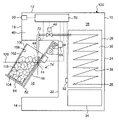
ブラケット58の上方に位置する側板部分の背面には、側板56を前方から後方に向かって見たとき、側板56の略中央部に、前後方向に伸びる垂直面に沿って配置された一つのガイドプレート60が固定されている。ガイドプレート60には、上下方向に伸びる長孔62が形成されている。これに対応して、ハウジング前壁22には傾斜手段のリニアヘッド64が固定されている。リニアヘッド64は、筐体の内部に収容されたモータ、減速機及びピニオンと、筐体の前後壁を貫通して前後方向に伸びるラック(駆動シャフト)66を備えており、モータの回転を減速機で減速してピニオンに伝達し、ピニオンの回転をラック66の前後運動に変換するように構成されており、ラック66の先端に取り付けた係合ピン68がガイドプレート60の長孔62に係合させてある。したがって、リニアヘッド64を駆動する(モータを正逆回転する)ことにより、容器載置台52を図1に示す非傾斜位置と図2に示す傾斜位置との間を移動することができる。図示するように、非傾斜位置は、容器載置台52の底板54が水平又はほぼ水平に設けられ、側板56が垂直又はほぼ垂直に向けられた状態である。ただし、実施形態において、非傾斜位置は、容器102を垂直に支持する位置又は状態に限るものでなく、傾斜位置における容器102の傾斜角度よりも小さな傾斜角度で容器102を支持する位置又は状態をも含む。一方、傾斜位置は、容器載置台52が非傾斜位置から約30度前方(図1におおいて時計回り方向)に揺動した状態である。
On the back surface of the side plate portion located above the bracket 58, one guide arranged along a vertical plane extending in the front-rear direction at a substantially central portion of the side plate 56 when the side plate 56 is viewed from the front to the rear. The plate 60 is fixed. The guide plate 60 is formed with an elongated hole 62 extending in the vertical direction. Correspondingly, the linear head 64 of the tilting means is fixed to the front wall 22 of the housing. The linear head 64 includes a motor, a speed reducer, and a pinion housed inside the housing, and a rack (drive shaft) 66 extending in the front-rear direction through the front and rear walls of the housing to reduce the rotation of the motor. It is configured to decelerate with a machine and transmit it to the pinion, converting the rotation of the pinion into the back-and-forth movement of the rack 66, and the engaging pin 68 attached to the tip of the rack 66 engages with the elongated hole 62 of the guide plate 60. It is matched. Therefore, by driving the linear head 64 (rotating the motor in the forward and reverse directions), the container mounting table 52 can be moved between the non-tilted position shown in FIG. 1 and the tilted position shown in FIG. As shown in the figure, the non-tilted position is a state in which the bottom plate 54 of the container mounting table 52 is provided horizontally or substantially horizontally, and the side plate 56 is oriented vertically or substantially vertically. However, in the embodiment, the non-tilted position is not limited to the position or state of vertically supporting the container 102, but the position or state of supporting the container 102 at an inclination angle smaller than the inclination angle of the container 102 in the inclined position. Also includes. On the other hand, the tilted position is a state in which the container mounting table 52 swings forward about 30 degrees (clockwise in FIG. 1) from the non-tilted position.

JP2019109882A 2019-06-12 2019-06-12 beverage dispenser Active JP7336096B2 (en)

Priority Applications (2)

Application Number Priority Date Filing Date Title
JP2019109882A JP7336096B2 (en) 2019-06-12 2019-06-12 beverage dispenser
PCT/JP2020/023076 WO2020250990A1 (en) 2019-06-12 2020-06-11 Automatic beverage pouring device

Applications Claiming Priority (1)

Application Number Priority Date Filing Date Title
JP2019109882A JP7336096B2 (en) 2019-06-12 2019-06-12 beverage dispenser

Publications (3)

Publication Number Publication Date
JP2020200096A JP2020200096A (en) 2020-12-17
JP2020200096A5 true JP2020200096A5 (en) 2022-04-25
JP7336096B2 JP7336096B2 (en) 2023-08-31

Family

ID=73743663

Family Applications (1)

Application Number Title Priority Date Filing Date
JP2019109882A Active JP7336096B2 (en) 2019-06-12 2019-06-12 beverage dispenser

Country Status (2)

Country Link
JP (1) JP7336096B2 (en)
WO (1) WO2020250990A1 (en)

Families Citing this family (1)

* Cited by examiner, † Cited by third party
Publication number Priority date Publication date Assignee Title
JP7629169B2 (en) * 2021-02-15 2025-02-13 株式会社デジアイズ Carbonated water maker

Family Cites Families (6)

* Cited by examiner, † Cited by third party
Publication number Priority date Publication date Assignee Title
US4559979A (en) * 1983-12-08 1985-12-24 The Coca-Cola Company Ultrasound level detector
JP2616126B2 (en) * 1990-04-09 1997-06-04 富士電機株式会社 Beer dispenser
JP2933369B2 (en) * 1990-09-27 1999-08-09 東芝機械株式会社 Automatic dispensing device for sparkling beverages
JP4497356B2 (en) 2004-07-22 2010-07-07 ホシザキ電機株式会社 Beverage dispenser
CA2750000C (en) 2009-01-19 2016-08-02 Nicevend Ltd. Apparatus for dispensing made-to-order frozen beverage
JP6966834B2 (en) 2015-06-02 2021-11-17 ホシザキ株式会社 Beverage automatic dispensing device

Similar Documents

Publication Publication Date Title
JP6215101B2 (en) Portable cutting machine
JP5886941B2 (en) Welding trolley
JP2017127770A5 (en)
CN101505640A (en) Cooker movement method and device
CN102080760A (en) Self-balance space scanning support
JPWO2012042991A1 (en) Shot processing device
CN104416225A (en) Reciprocating saw
CN209022083U (en) A kind of multifunction manipulator fixture
JP5490571B2 (en) Vehicle seat
JP2019005847A5 (en)
JP2015178226A (en) Portable cutting machine
JP7332366B2 (en) Tracking device for bending machines
CN106955931B (en) Oblique all-in-one machine is made in the flattening of evaporator aluminum comb
CN218768269U (en) Hopper assembly of retail cabinet
JP2013022168A (en) Movable performance device of game machine
CN207577564U (en) A kind of cutter lifting structure of reciprocating saw
CN103447614A (en) Electric reciprocating saw
JP5507983B2 (en) Circular saw
JP2013095166A (en) Vehicle seat
JP2012170990A (en) Swing drive mechanism
JP3155852U (en) Turntable
JP2018035881A (en) Rotating linear drive device
JP2009214266A (en) Feeding device of barrel polishing machine
TWI337857B (en)
CN110486312B (en) Oscillating mechanism and fan