JP2020200945A - トルクダンパ装置 - Google Patents
トルクダンパ装置 Download PDFInfo
- Publication number
- JP2020200945A JP2020200945A JP2020095914A JP2020095914A JP2020200945A JP 2020200945 A JP2020200945 A JP 2020200945A JP 2020095914 A JP2020095914 A JP 2020095914A JP 2020095914 A JP2020095914 A JP 2020095914A JP 2020200945 A JP2020200945 A JP 2020200945A
- Authority
- JP
- Japan
- Prior art keywords
- plate
- torque
- damper device
- spring member
- torque damper
- Prior art date
- Legal status (The legal status is an assumption and is not a legal conclusion. Google has not performed a legal analysis and makes no representation as to the accuracy of the status listed.)
- Granted
Links
Images



Classifications
-
- F—MECHANICAL ENGINEERING; LIGHTING; HEATING; WEAPONS; BLASTING
- F16—ENGINEERING ELEMENTS AND UNITS; GENERAL MEASURES FOR PRODUCING AND MAINTAINING EFFECTIVE FUNCTIONING OF MACHINES OR INSTALLATIONS; THERMAL INSULATION IN GENERAL
- F16H—GEARING
- F16H45/00—Combinations of fluid gearings for conveying rotary motion with couplings or clutches
- F16H45/02—Combinations of fluid gearings for conveying rotary motion with couplings or clutches with mechanical clutches for bridging a fluid gearing of the hydrokinetic type
-
- F—MECHANICAL ENGINEERING; LIGHTING; HEATING; WEAPONS; BLASTING
- F16—ENGINEERING ELEMENTS AND UNITS; GENERAL MEASURES FOR PRODUCING AND MAINTAINING EFFECTIVE FUNCTIONING OF MACHINES OR INSTALLATIONS; THERMAL INSULATION IN GENERAL
- F16F—SPRINGS; SHOCK-ABSORBERS; MEANS FOR DAMPING VIBRATION
- F16F15/00—Suppression of vibrations in systems; Means or arrangements for avoiding or reducing out-of-balance forces, e.g. due to motion
- F16F15/10—Suppression of vibrations in rotating systems by making use of members moving with the system
- F16F15/12—Suppression of vibrations in rotating systems by making use of members moving with the system using elastic members or friction-damping members, e.g. between a rotating shaft and a gyratory mass mounted thereon
- F16F15/121—Suppression of vibrations in rotating systems by making use of members moving with the system using elastic members or friction-damping members, e.g. between a rotating shaft and a gyratory mass mounted thereon using springs as elastic members, e.g. metallic springs
- F16F15/123—Wound springs
- F16F15/1232—Wound springs characterised by the spring mounting
-
- F—MECHANICAL ENGINEERING; LIGHTING; HEATING; WEAPONS; BLASTING
- F16—ENGINEERING ELEMENTS AND UNITS; GENERAL MEASURES FOR PRODUCING AND MAINTAINING EFFECTIVE FUNCTIONING OF MACHINES OR INSTALLATIONS; THERMAL INSULATION IN GENERAL
- F16H—GEARING
- F16H45/00—Combinations of fluid gearings for conveying rotary motion with couplings or clutches
-
- F—MECHANICAL ENGINEERING; LIGHTING; HEATING; WEAPONS; BLASTING
- F16—ENGINEERING ELEMENTS AND UNITS; GENERAL MEASURES FOR PRODUCING AND MAINTAINING EFFECTIVE FUNCTIONING OF MACHINES OR INSTALLATIONS; THERMAL INSULATION IN GENERAL
- F16D—COUPLINGS FOR TRANSMITTING ROTATION; CLUTCHES; BRAKES
- F16D3/00—Yielding couplings, i.e. with means permitting movement between the connected parts during the drive
- F16D3/02—Yielding couplings, i.e. with means permitting movement between the connected parts during the drive adapted to specific functions
- F16D3/12—Yielding couplings, i.e. with means permitting movement between the connected parts during the drive adapted to specific functions specially adapted for accumulation of energy to absorb shocks or vibration
-
- F—MECHANICAL ENGINEERING; LIGHTING; HEATING; WEAPONS; BLASTING
- F16—ENGINEERING ELEMENTS AND UNITS; GENERAL MEASURES FOR PRODUCING AND MAINTAINING EFFECTIVE FUNCTIONING OF MACHINES OR INSTALLATIONS; THERMAL INSULATION IN GENERAL
- F16F—SPRINGS; SHOCK-ABSORBERS; MEANS FOR DAMPING VIBRATION
- F16F15/00—Suppression of vibrations in systems; Means or arrangements for avoiding or reducing out-of-balance forces, e.g. due to motion
- F16F15/10—Suppression of vibrations in rotating systems by making use of members moving with the system
- F16F15/12—Suppression of vibrations in rotating systems by making use of members moving with the system using elastic members or friction-damping members, e.g. between a rotating shaft and a gyratory mass mounted thereon
- F16F15/121—Suppression of vibrations in rotating systems by making use of members moving with the system using elastic members or friction-damping members, e.g. between a rotating shaft and a gyratory mass mounted thereon using springs as elastic members, e.g. metallic springs
- F16F15/123—Wound springs
-
- F—MECHANICAL ENGINEERING; LIGHTING; HEATING; WEAPONS; BLASTING
- F16—ENGINEERING ELEMENTS AND UNITS; GENERAL MEASURES FOR PRODUCING AND MAINTAINING EFFECTIVE FUNCTIONING OF MACHINES OR INSTALLATIONS; THERMAL INSULATION IN GENERAL
- F16F—SPRINGS; SHOCK-ABSORBERS; MEANS FOR DAMPING VIBRATION
- F16F15/00—Suppression of vibrations in systems; Means or arrangements for avoiding or reducing out-of-balance forces, e.g. due to motion
- F16F15/10—Suppression of vibrations in rotating systems by making use of members moving with the system
- F16F15/12—Suppression of vibrations in rotating systems by making use of members moving with the system using elastic members or friction-damping members, e.g. between a rotating shaft and a gyratory mass mounted thereon
- F16F15/121—Suppression of vibrations in rotating systems by making use of members moving with the system using elastic members or friction-damping members, e.g. between a rotating shaft and a gyratory mass mounted thereon using springs as elastic members, e.g. metallic springs
- F16F15/123—Wound springs
- F16F15/12353—Combinations of dampers, e.g. with multiple plates, multiple spring sets, i.e. complex configurations
- F16F15/1236—Combinations of dampers, e.g. with multiple plates, multiple spring sets, i.e. complex configurations resulting in a staged spring characteristic, e.g. with multiple intermediate plates
- F16F15/12366—Combinations of dampers, e.g. with multiple plates, multiple spring sets, i.e. complex configurations resulting in a staged spring characteristic, e.g. with multiple intermediate plates acting on multiple sets of springs
-
- F—MECHANICAL ENGINEERING; LIGHTING; HEATING; WEAPONS; BLASTING
- F16—ENGINEERING ELEMENTS AND UNITS; GENERAL MEASURES FOR PRODUCING AND MAINTAINING EFFECTIVE FUNCTIONING OF MACHINES OR INSTALLATIONS; THERMAL INSULATION IN GENERAL
- F16D—COUPLINGS FOR TRANSMITTING ROTATION; CLUTCHES; BRAKES
- F16D25/00—Fluid-actuated clutches
- F16D25/06—Fluid-actuated clutches in which the fluid actuates a piston incorporated in, i.e. rotating with the clutch
- F16D25/062—Fluid-actuated clutches in which the fluid actuates a piston incorporated in, i.e. rotating with the clutch the clutch having friction surfaces
- F16D25/063—Fluid-actuated clutches in which the fluid actuates a piston incorporated in, i.e. rotating with the clutch the clutch having friction surfaces with clutch members exclusively moving axially
- F16D25/0635—Fluid-actuated clutches in which the fluid actuates a piston incorporated in, i.e. rotating with the clutch the clutch having friction surfaces with clutch members exclusively moving axially with flat friction surfaces, e.g. discs
- F16D25/0638—Fluid-actuated clutches in which the fluid actuates a piston incorporated in, i.e. rotating with the clutch the clutch having friction surfaces with clutch members exclusively moving axially with flat friction surfaces, e.g. discs with more than two discs, e.g. multiple lamellae
-
- F—MECHANICAL ENGINEERING; LIGHTING; HEATING; WEAPONS; BLASTING
- F16—ENGINEERING ELEMENTS AND UNITS; GENERAL MEASURES FOR PRODUCING AND MAINTAINING EFFECTIVE FUNCTIONING OF MACHINES OR INSTALLATIONS; THERMAL INSULATION IN GENERAL
- F16D—COUPLINGS FOR TRANSMITTING ROTATION; CLUTCHES; BRAKES
- F16D33/00—Rotary fluid couplings or clutches of the hydrokinetic type
-
- F—MECHANICAL ENGINEERING; LIGHTING; HEATING; WEAPONS; BLASTING
- F16—ENGINEERING ELEMENTS AND UNITS; GENERAL MEASURES FOR PRODUCING AND MAINTAINING EFFECTIVE FUNCTIONING OF MACHINES OR INSTALLATIONS; THERMAL INSULATION IN GENERAL
- F16F—SPRINGS; SHOCK-ABSORBERS; MEANS FOR DAMPING VIBRATION
- F16F2238/00—Type of springs or dampers
- F16F2238/02—Springs
- F16F2238/026—Springs wound- or coil-like
-
- F—MECHANICAL ENGINEERING; LIGHTING; HEATING; WEAPONS; BLASTING
- F16—ENGINEERING ELEMENTS AND UNITS; GENERAL MEASURES FOR PRODUCING AND MAINTAINING EFFECTIVE FUNCTIONING OF MACHINES OR INSTALLATIONS; THERMAL INSULATION IN GENERAL
- F16H—GEARING
- F16H45/00—Combinations of fluid gearings for conveying rotary motion with couplings or clutches
- F16H2045/007—Combinations of fluid gearings for conveying rotary motion with couplings or clutches comprising a damper between turbine of the fluid gearing and the mechanical gearing unit
-
- F—MECHANICAL ENGINEERING; LIGHTING; HEATING; WEAPONS; BLASTING
- F16—ENGINEERING ELEMENTS AND UNITS; GENERAL MEASURES FOR PRODUCING AND MAINTAINING EFFECTIVE FUNCTIONING OF MACHINES OR INSTALLATIONS; THERMAL INSULATION IN GENERAL
- F16H—GEARING
- F16H45/00—Combinations of fluid gearings for conveying rotary motion with couplings or clutches
- F16H45/02—Combinations of fluid gearings for conveying rotary motion with couplings or clutches with mechanical clutches for bridging a fluid gearing of the hydrokinetic type
- F16H2045/0205—Combinations of fluid gearings for conveying rotary motion with couplings or clutches with mechanical clutches for bridging a fluid gearing of the hydrokinetic type two chamber system, i.e. without a separated, closed chamber specially adapted for actuating a lock-up clutch
-
- F—MECHANICAL ENGINEERING; LIGHTING; HEATING; WEAPONS; BLASTING
- F16—ENGINEERING ELEMENTS AND UNITS; GENERAL MEASURES FOR PRODUCING AND MAINTAINING EFFECTIVE FUNCTIONING OF MACHINES OR INSTALLATIONS; THERMAL INSULATION IN GENERAL
- F16H—GEARING
- F16H45/00—Combinations of fluid gearings for conveying rotary motion with couplings or clutches
- F16H45/02—Combinations of fluid gearings for conveying rotary motion with couplings or clutches with mechanical clutches for bridging a fluid gearing of the hydrokinetic type
- F16H2045/0221—Combinations of fluid gearings for conveying rotary motion with couplings or clutches with mechanical clutches for bridging a fluid gearing of the hydrokinetic type with damping means
- F16H2045/0226—Combinations of fluid gearings for conveying rotary motion with couplings or clutches with mechanical clutches for bridging a fluid gearing of the hydrokinetic type with damping means comprising two or more vibration dampers
-
- F—MECHANICAL ENGINEERING; LIGHTING; HEATING; WEAPONS; BLASTING
- F16—ENGINEERING ELEMENTS AND UNITS; GENERAL MEASURES FOR PRODUCING AND MAINTAINING EFFECTIVE FUNCTIONING OF MACHINES OR INSTALLATIONS; THERMAL INSULATION IN GENERAL
- F16H—GEARING
- F16H45/00—Combinations of fluid gearings for conveying rotary motion with couplings or clutches
- F16H45/02—Combinations of fluid gearings for conveying rotary motion with couplings or clutches with mechanical clutches for bridging a fluid gearing of the hydrokinetic type
- F16H2045/0221—Combinations of fluid gearings for conveying rotary motion with couplings or clutches with mechanical clutches for bridging a fluid gearing of the hydrokinetic type with damping means
- F16H2045/0226—Combinations of fluid gearings for conveying rotary motion with couplings or clutches with mechanical clutches for bridging a fluid gearing of the hydrokinetic type with damping means comprising two or more vibration dampers
- F16H2045/0231—Combinations of fluid gearings for conveying rotary motion with couplings or clutches with mechanical clutches for bridging a fluid gearing of the hydrokinetic type with damping means comprising two or more vibration dampers arranged in series
-
- F—MECHANICAL ENGINEERING; LIGHTING; HEATING; WEAPONS; BLASTING
- F16—ENGINEERING ELEMENTS AND UNITS; GENERAL MEASURES FOR PRODUCING AND MAINTAINING EFFECTIVE FUNCTIONING OF MACHINES OR INSTALLATIONS; THERMAL INSULATION IN GENERAL
- F16H—GEARING
- F16H45/00—Combinations of fluid gearings for conveying rotary motion with couplings or clutches
- F16H45/02—Combinations of fluid gearings for conveying rotary motion with couplings or clutches with mechanical clutches for bridging a fluid gearing of the hydrokinetic type
- F16H2045/0273—Combinations of fluid gearings for conveying rotary motion with couplings or clutches with mechanical clutches for bridging a fluid gearing of the hydrokinetic type characterised by the type of the friction surface of the lock-up clutch
- F16H2045/0284—Multiple disk type lock-up clutch
Landscapes
- Engineering & Computer Science (AREA)
- General Engineering & Computer Science (AREA)
- Mechanical Engineering (AREA)
- Physics & Mathematics (AREA)
- Acoustics & Sound (AREA)
- Aviation & Aerospace Engineering (AREA)
- Mechanical Operated Clutches (AREA)
Abstract
Description
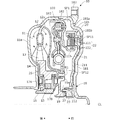
ロックアップ機構の作動時において、カバー18とタービンハブ19とが直接連結されると、エンジンの回転変動によって生じるトルク振動が変速機に直接伝達される。これを避けるため、ロックアップクラッチ20とタービンハブ19との間に、振動減衰機能を有するトルクダンパ装置100が配置される。トルクダンパ装置100は、ロックアップクラッチ20からタービンハブ19(出力軸)までのトルク伝達経路に介装され、軸線CLを中心として回転可能に設けられる。
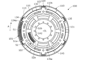
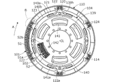
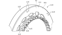
(1)トルクダンパ装置100は、エンジンから出力されたトルクが入力されるロックアップクラッチ20からタービンハブ19までのトルク伝達経路に介装され、軸線CLを中心に回転可能に設けられる(図1)。このトルクダンパ装置100は、ロックアップクラッチ20からトルクが入力されるドライブプレート110(入力プレート)と、ドライブプレート110に締結されたホルダプレート120(中間プレート)と、ホルダプレート120からトルクが伝達されるトルク伝達プレート130(出力プレート)と、ホルダプレート120からトルク伝達プレート130に伝達されるトルクが減衰されるようにホルダプレート120とトルク伝達プレート130との間に介装された一次ダンパスプリングS1(ばね部材)と、を備える(図2〜4)。トルク伝達プレート130は、軸方向に離間して配置された第1プレート部材131および第2プレート部材132(一対のプレート部材)と、一対のプレート部材131,132を一体に締結するリベットR3(締結部)と、を有する(図2)。一次ダンパスプリングS1は、軸線CLを中心とする周方向に伸縮可能に配置されたコイルばねとして構成される(図3,4)。ホルダプレート120は、一次ダンパスプリングS1の径方向内側の端部を保持するばね保持部123と、一対のプレート部材131,132の間をばね保持部123から径方向内側に向けて延設され、リベットR3に対し相対回転可能に支持された板部121と、を有する(図2)。
Claims (12)
- エンジンから出力されたトルクが入力されるクラッチ装置から出力軸までのトルク伝達経路に介装され、軸線を中心に回転可能に設けられたトルクダンパ装置であって、
前記クラッチ装置からトルクが入力される入力プレートと、
前記入力プレートに締結された中間プレートと、
前記中間プレートからトルクが伝達される出力プレートと、
前記中間プレートから前記出力プレートに伝達されるトルクが減衰されるように前記中間プレートと前記出力プレートとの間に介装されたばね部材と、を備え、
前記出力プレートは、軸方向に離間して配置された一対のプレート部材と、前記一対のプレート部材を一体に締結する締結部と、を有し、
前記ばね部材は、前記軸線を中心とする周方向に伸縮可能に配置されたコイルばねであり、
前記中間プレートは、前記ばね部材の径方向内側の端部を保持するばね保持部と、前記一対のプレート部材の間を前記ばね保持部から径方向内側に向けて延設され、前記締結部に対し相対回転可能に支持されたプレート部と、を有することを特徴とするトルクダンパ装置。 - 請求項1に記載のトルクダンパ装置において、
前記プレート部は、前記ばね部材の径方向内側における前記ばね部材の軸方向一端部から他端部までの間の空間に配置されることを特徴とするトルクダンパ装置。 - 請求項1または2に記載のトルクダンパ装置において、
前記入力プレートは、前記ばね部材の径方向外側の端部を保持するばね保持部を有することを特徴とするトルクダンパ装置。 - 請求項1から3のいずれか1項に記載のトルクダンパ装置において、
前記入力プレートは、径方向に延在するプレート部と、前記プレート部の外径側端部から軸方向に延在する外径側プレート部と、を有し、
前記一対のプレート部材は、第1プレート部材と、前記第1プレート部材と前記入力プレートの前記プレート部との間に配置された第2プレート部材であり、
前記ばね部材は、前記第1プレート部材と前記入力プレートの前記プレート部との間に配置されるとともに、前記入力プレートの前記外径側プレート部に面して周方向に互いに所定間隔を空けてそれぞれ配置された第1ばね部材と第2ばね部材とを含むことを特徴とするトルクダンパ装置。 - 請求項4に記載のトルクダンパ装置において、
前記出力プレートは、互いに対向する前記第1ばね部材の周方向端面と前記第2ばね部材の周方向端面との間に配置され、前記ばね部材により減衰されたトルクが入力される断面略L字状のトルク入力部を有することを特徴とするトルクダンパ装置。 - 請求項4または5に記載のトルクダンパ装置において、
前記中間プレートは、互いに対向する前記第1ばね部材の周方向端面と前記第2ばね部材の周方向端面との間に配置され、前記ばね部材にトルクを伝達する断面略C字状のトルク伝達部をさらに有することを特徴とするトルクダンパ装置。 - 請求項1から5のいずれか1項に記載のトルクダンパ装置において、
前記出力プレートは、第1出力プレートであり、
前記ばね部材は、一次ばね部材であり、
前記第1出力プレートから出力されたトルクが伝達される第2出力プレートと、
前記第1出力プレートから前記第2出力プレートに伝達されるトルクが減衰されるように前記第1出力プレートと前記第2出力プレートとの間に介装された二次ばね部材と、をさらに備えることを特徴とするトルクダンパ装置。 - 請求項7に記載のトルクダンパ装置において、
前記二次ばね部材は、前記締結部の径方向内側に配置されることを特徴とするトルクダンパ装置。 - 請求項7または8に記載のトルクダンパ装置において、
前記一次ばね部材と前記二次ばね部材とは、軸方向略同一位置に配置されることを特徴とするトルクダンパ装置。 - 請求項1から9のいずれか1項に記載のトルクダンパ装置において、
前記入力プレートは、前記クラッチ装置のクラッチ板を軸方向に移動可能に係合する係合部を有することを特徴とするトルクダンパ装置。 - 請求項10に記載のトルクダンパ装置において、
前記入力プレートは、径方向に延在するプレート部と、前記プレート部の内径側端部から軸方向に突設された前記軸線を中心とした略円筒形状のハブ部と、を有し、
前記係合部は、前記ハブ部の周面に形成されることを特徴とするトルクダンパ装置。 - 請求項1から11のいずれか1項に記載のトルクダンパ装置において、
前記軸線は、前記出力軸の中心軸であることを特徴とするトルクダンパ装置。
Applications Claiming Priority (2)
| Application Number | Priority Date | Filing Date | Title |
|---|---|---|---|
| JP2019106663 | 2019-06-07 | ||
| JP2019106663 | 2019-06-07 |
Publications (2)
| Publication Number | Publication Date |
|---|---|
| JP2020200945A true JP2020200945A (ja) | 2020-12-17 |
| JP7038757B2 JP7038757B2 (ja) | 2022-03-18 |
Family
ID=73609416
Family Applications (1)
| Application Number | Title | Priority Date | Filing Date |
|---|---|---|---|
| JP2020095914A Active JP7038757B2 (ja) | 2019-06-07 | 2020-06-02 | トルクダンパ装置 |
Country Status (3)
| Country | Link |
|---|---|
| US (1) | US20200386274A1 (ja) |
| JP (1) | JP7038757B2 (ja) |
| CN (1) | CN112049914B (ja) |
Families Citing this family (1)
| Publication number | Priority date | Publication date | Assignee | Title |
|---|---|---|---|---|
| US11560941B1 (en) * | 2022-01-11 | 2023-01-24 | Schaeffler Technologies AG & Co. KG | Reaction plate with an uneven number of tabs in drive and coast |
Citations (4)
| Publication number | Priority date | Publication date | Assignee | Title |
|---|---|---|---|---|
| JP2011169419A (ja) * | 2010-02-19 | 2011-09-01 | Honda Motor Co Ltd | ねじりダンパ装置 |
| JP2012077827A (ja) * | 2010-09-30 | 2012-04-19 | Aisin Aw Co Ltd | 流体伝動装置 |
| JP2013117283A (ja) * | 2011-12-05 | 2013-06-13 | Exedy Corp | トルクコンバータのロックアップ装置 |
| JP2017075661A (ja) * | 2015-10-16 | 2017-04-20 | 株式会社ユタカ技研 | 流体式動力伝達装置 |
Family Cites Families (4)
| Publication number | Priority date | Publication date | Assignee | Title |
|---|---|---|---|---|
| US4693348A (en) * | 1985-04-30 | 1987-09-15 | Aisin Warner Kabushiki Kaisha | Direct coupling clutch with an integral damper device for a fluid coupling |
| JP2001227617A (ja) * | 2000-02-17 | 2001-08-24 | Exedy Corp | 流体式トルク伝達装置 |
| JP6386487B2 (ja) * | 2016-03-01 | 2018-09-05 | 本田技研工業株式会社 | トルク伝達装置 |
| JP6505035B2 (ja) * | 2016-03-01 | 2019-04-24 | 本田技研工業株式会社 | トルク伝達装置 |
-
2020
- 2020-05-28 US US16/885,473 patent/US20200386274A1/en not_active Abandoned
- 2020-06-01 CN CN202010485828.6A patent/CN112049914B/zh active Active
- 2020-06-02 JP JP2020095914A patent/JP7038757B2/ja active Active
Patent Citations (4)
| Publication number | Priority date | Publication date | Assignee | Title |
|---|---|---|---|---|
| JP2011169419A (ja) * | 2010-02-19 | 2011-09-01 | Honda Motor Co Ltd | ねじりダンパ装置 |
| JP2012077827A (ja) * | 2010-09-30 | 2012-04-19 | Aisin Aw Co Ltd | 流体伝動装置 |
| JP2013117283A (ja) * | 2011-12-05 | 2013-06-13 | Exedy Corp | トルクコンバータのロックアップ装置 |
| JP2017075661A (ja) * | 2015-10-16 | 2017-04-20 | 株式会社ユタカ技研 | 流体式動力伝達装置 |
Also Published As
| Publication number | Publication date |
|---|---|
| CN112049914A (zh) | 2020-12-08 |
| CN112049914B (zh) | 2024-06-25 |
| JP7038757B2 (ja) | 2022-03-18 |
| US20200386274A1 (en) | 2020-12-10 |
Similar Documents
| Publication | Publication Date | Title |
|---|---|---|
| RU2640938C2 (ru) | Гидродинамическая муфта | |
| CN103958936A (zh) | 扭矩变换器的锁定装置 | |
| JP6277053B2 (ja) | トルクコンバータ | |
| JP4073749B2 (ja) | 流体式トルク伝達装置のロックアップ装置 | |
| JP7038757B2 (ja) | トルクダンパ装置 | |
| JP2002089658A (ja) | 弾性連結機構及びトルクコンバータのロックアップ装置 | |
| JP2007113661A (ja) | 流体式トルク伝達装置およびそれに用いられるロックアップ装置 | |
| JP2012077810A (ja) | 流体伝動装置およびその製造方法 | |
| JP2002310262A (ja) | 流体式トルク伝達装置のロックアップ装置 | |
| JP7208820B2 (ja) | ロックアップ装置 | |
| JP2007113659A (ja) | 流体式トルク伝達装置およびそれに用いられるロックアップ装置 | |
| JP7451308B2 (ja) | ロックアップ装置 | |
| JP2006183776A (ja) | 流体式トルク伝達装置のロックアップ装置 | |
| US10082190B2 (en) | Lock-up device for torque converter | |
| JP2007113660A (ja) | 流体式トルク伝達装置およびそれに用いられるロックアップ装置 | |
| JP2004156692A (ja) | 流体式トルク伝達装置のロックアップ装置 | |
| JP3475703B2 (ja) | ロックアップクラッチ構造 | |
| JP7451307B2 (ja) | ロックアップ装置 | |
| JPH10213204A (ja) | トルクコンバータのロックアップダンパー | |
| JP7477370B2 (ja) | ロックアップ装置 | |
| JP7577225B2 (ja) | 発進装置 | |
| JP2004003678A (ja) | 動力伝達装置 | |
| JP2006162054A (ja) | ダンパーディスク組立体 | |
| JPS60260765A (ja) | 吸振ダンパ装置付直結クラツチを備えた流体継手 | |
| JP2015206453A (ja) | トルクコンバータ |
Legal Events
| Date | Code | Title | Description |
|---|---|---|---|
| A621 | Written request for application examination |
Free format text: JAPANESE INTERMEDIATE CODE: A621 Effective date: 20200602 |
|
| AA64 | Notification of invalidation of claim of internal priority (with term) |
Free format text: JAPANESE INTERMEDIATE CODE: A241764 Effective date: 20200707 |
|
| A521 | Request for written amendment filed |
Free format text: JAPANESE INTERMEDIATE CODE: A523 Effective date: 20200730 |
|
| A977 | Report on retrieval |
Free format text: JAPANESE INTERMEDIATE CODE: A971007 Effective date: 20210730 |
|
| A131 | Notification of reasons for refusal |
Free format text: JAPANESE INTERMEDIATE CODE: A131 Effective date: 20210803 |
|
| A521 | Request for written amendment filed |
Free format text: JAPANESE INTERMEDIATE CODE: A523 Effective date: 20210928 |
|
| TRDD | Decision of grant or rejection written | ||
| A01 | Written decision to grant a patent or to grant a registration (utility model) |
Free format text: JAPANESE INTERMEDIATE CODE: A01 Effective date: 20220215 |
|
| A61 | First payment of annual fees (during grant procedure) |
Free format text: JAPANESE INTERMEDIATE CODE: A61 Effective date: 20220308 |
|
| R150 | Certificate of patent or registration of utility model |
Ref document number: 7038757 Country of ref document: JP Free format text: JAPANESE INTERMEDIATE CODE: R150 |
|
| R250 | Receipt of annual fees |
Free format text: JAPANESE INTERMEDIATE CODE: R250 |
|
| R250 | Receipt of annual fees |
Free format text: JAPANESE INTERMEDIATE CODE: R250 |