JP2020502402A - Track inspection vehicle and method of detecting track shape - Google Patents
Track inspection vehicle and method of detecting track shape Download PDFInfo
- Publication number
- JP2020502402A JP2020502402A JP2019532995A JP2019532995A JP2020502402A JP 2020502402 A JP2020502402 A JP 2020502402A JP 2019532995 A JP2019532995 A JP 2019532995A JP 2019532995 A JP2019532995 A JP 2019532995A JP 2020502402 A JP2020502402 A JP 2020502402A
- Authority
- JP
- Japan
- Prior art keywords
- measurement
- track
- inspection vehicle
- measuring
- base
- Prior art date
- Legal status (The legal status is an assumption and is not a legal conclusion. Google has not performed a legal analysis and makes no representation as to the accuracy of the status listed.)
- Granted
Links
Images


Classifications
-
- B—PERFORMING OPERATIONS; TRANSPORTING
- B61—RAILWAYS
- B61K—AUXILIARY EQUIPMENT SPECIALLY ADAPTED FOR RAILWAYS, NOT OTHERWISE PROVIDED FOR
- B61K9/00—Railway vehicle profile gauges; Detecting or indicating overheating of components; Apparatus on locomotives or cars to indicate bad track sections; General design of track recording vehicles
- B61K9/08—Measuring installations for surveying permanent way
-
- B—PERFORMING OPERATIONS; TRANSPORTING
- B61—RAILWAYS
- B61L—GUIDING RAILWAY TRAFFIC; ENSURING THE SAFETY OF RAILWAY TRAFFIC
- B61L23/00—Control, warning or like safety means along the route or between vehicles or trains
- B61L23/04—Control, warning or like safety means along the route or between vehicles or trains for monitoring the mechanical state of the route
- B61L23/042—Track changes detection
-
- E—FIXED CONSTRUCTIONS
- E01—CONSTRUCTION OF ROADS, RAILWAYS, OR BRIDGES
- E01B—PERMANENT WAY; PERMANENT-WAY TOOLS; MACHINES FOR MAKING RAILWAYS OF ALL KINDS
- E01B35/00—Applications of measuring apparatus or devices for track-building purposes
-
- G—PHYSICS
- G01—MEASURING; TESTING
- G01B—MEASURING LENGTH, THICKNESS OR SIMILAR LINEAR DIMENSIONS; MEASURING ANGLES; MEASURING AREAS; MEASURING IRREGULARITIES OF SURFACES OR CONTOURS
- G01B11/00—Measuring arrangements characterised by the use of optical techniques
- G01B11/26—Measuring arrangements characterised by the use of optical techniques for measuring angles or tapers; for testing the alignment of axes
-
- E—FIXED CONSTRUCTIONS
- E01—CONSTRUCTION OF ROADS, RAILWAYS, OR BRIDGES
- E01B—PERMANENT WAY; PERMANENT-WAY TOOLS; MACHINES FOR MAKING RAILWAYS OF ALL KINDS
- E01B2203/00—Devices for working the railway-superstructure
- E01B2203/06—Placing ballast
-
- E—FIXED CONSTRUCTIONS
- E01—CONSTRUCTION OF ROADS, RAILWAYS, OR BRIDGES
- E01B—PERMANENT WAY; PERMANENT-WAY TOOLS; MACHINES FOR MAKING RAILWAYS OF ALL KINDS
- E01B2203/00—Devices for working the railway-superstructure
- E01B2203/16—Guiding or measuring means, e.g. for alignment, canting, stepwise propagation
Landscapes
- Engineering & Computer Science (AREA)
- Mechanical Engineering (AREA)
- Architecture (AREA)
- Civil Engineering (AREA)
- Structural Engineering (AREA)
- Physics & Mathematics (AREA)
- General Physics & Mathematics (AREA)
- Machines For Laying And Maintaining Railways (AREA)
- Length Measuring Devices With Unspecified Measuring Means (AREA)
Abstract
本発明は、軌道(2)の軌道形状を検出するための軌道検測車(1)であって、軌道の2本のレール(3)上を走行可能でありかつレール走行装置(4)を有する車両フレーム(5)と、慣性測定ユニット(8)および各レール(3)に対する位置測定用の少なくとも1つの無接触式の位置測定装置(9)が配置された第1の測定基部(7)とを備えた軌道検測車(1)に関する。降下可能な第2の測定基部(11)が配置されていることが想定されており、第2の測定基部(11)は、レール(3)上に載置可能な測定従輪(12)を有しており、かつ補償測定装置(20,22)を介して第1の測定基部(7)に結合されている。The present invention relates to a track inspection vehicle (1) for detecting the track shape of a track (2), which is capable of running on two rails (3) of the track and using a rail travel device (4). A first measuring base (7) on which a vehicle frame (5) having at least one contactless position measuring device (9) for position measurement with respect to the inertial measuring unit (8) and each rail (3) is arranged; And a track inspection vehicle (1) comprising: It is assumed that a second measurement base (11) that can be lowered is arranged, and the second measurement base (11) has a measurement follower (12) that can be mounted on the rail (3). And is connected to the first measurement base (7) via compensation measuring devices (20, 22).
Description
本発明は、軌道の2本のレール上を走行可能でありかつレール走行装置を有する車両フレームと、慣性測定ユニットおよび各レールに対する位置測定用の少なくとも1つの無接触式の位置測定装置が配置された第1の測定基部とを備えた、軌道の軌道形状(Gleisgeometrie)を検出するための軌道検測車に関する。さらに本発明は、このような軌道検測車の作動方法に関する。 The invention comprises a vehicle frame which can run on two rails of a track and has a rail running device, an inertial measuring unit and at least one non-contact position measuring device for position measurement on each rail. And a first measurement base for detecting a track shape (Gleisgeometrie) of the track. Further, the present invention relates to a method of operating such a track inspection vehicle.
軌道の保守作業には、定期的な点検が必要である。このために、定期的な間隔で、軌道検測車の形態の軌道測定装置でもって軌道を走行し、軌道検測車が軌道形状を検出し、次いで軌道形状を評価する。軌道形状は、レール上を走行する車両の走行動力学に直接に影響を及ぼすので、軌道安全性を評価するためには精密な測定が重要である。したがって、軌道検測車は既にかなり以前から知られている。 Track maintenance requires periodic inspections. For this purpose, the vehicle travels on a track at regular intervals with a track measuring device in the form of a track test vehicle, which detects the track shape and then evaluates the track shape. Since the track shape directly affects the running dynamics of a vehicle running on a rail, precise measurement is important for evaluating track safety. Therefore, track inspection vehicles have been known for quite some time.
可動のポイントセンサでもって軌道と常時接触している機械的なセンサを備えた測定システムを使用することが多い。センサの動きから、次いで軌道形状を導出することができる。このような装置は、例えば独国特許出願公開第3914830号明細書から公知である。 Measuring systems with mechanical sensors that are always in contact with the track with movable point sensors are often used. From the movement of the sensor, the trajectory shape can then be derived. Such a device is known, for example, from DE 3914830 A1.
比較的新しい光学測定システムおよび慣性測定システムでは、所望の軌道形状測定データを導出するために、無接触式のレーザセンサが用いられる。鉛直方向の軌道位置は、座標系に関連付けられる2つの距離測定値の差から算出される。これにより、機械的な測定システムの速度制限も克服される。 In newer optical and inertial measurement systems, non-contact laser sensors are used to derive desired track shape measurement data. The vertical trajectory position is calculated from the difference between the two distance measurements associated with the coordinate system. This also overcomes the speed limitation of mechanical measurement systems.
しかしながら、軌道上に雪または砂の吹きだまりがある場合、光学測定システムはその限界に突き当たり、したがって軌道形状を正しく検出することも、もはや不可能である。独国特許出願公開第4136904号明細書からは、例えば軌道のレール間隔を無接触式に測定する装置が公知である。慣性測定システムは、専門雑誌“Eisenbahningenieur (52) 9/2001”の第6〜9頁に記載されている。
However, if there is snow or sand drips on the track, the optical measurement system will hit its limits and therefore it will no longer be possible to correctly detect the track shape. German Patent Application DE 41 36 904 A1 discloses, for example, a device for measuring the rail spacing of a track in a contactless manner. The inertial measurement system is described on
本発明の根底を成す課題は、冒頭で述べた形式の軌道検測車に関して、従来技術と比較した改良点を示すことにある。別の課題は、改良された軌道検測車の作動方法を説明することにある。 The problem underlying the present invention is to show an improvement over a track inspection vehicle of the type mentioned at the beginning compared to the prior art. Another object is to describe an improved method of operating a track inspection vehicle.
これらの課題は、本発明に基づき、請求項1記載の軌道検測車および請求項14記載の方法によって解決される。各従属請求項には本発明の有利な構成が記載されている。
These objects are achieved according to the invention by a track inspection vehicle according to claim 1 and a method according to
本発明は、降下可能な第2の測定基部が配置されていることを想定しており、第2の測定基部は、レール上に載置可能な測定従輪を有しておりかつ補償測定装置を介して第1の測定基部に結合されている。よって、無接触式の位置測定装置が、例えば強い雨、雪または砂の吹きだまりによりその限界に突き当たると直ちに、降下可能な機械的な第2の測定基部による軌道測定を、間を置かずに継続することができる。この場合、補償測定装置は、慣性測定ユニットに対する第2の測定基部の位置変化を連続的に検出する。これにより、慣性測定ユニットの測定データから軌道形状を簡単に導出することができる。 The invention assumes that a second measuring base which can be lowered is arranged, wherein the second measuring base has a measuring follower which can be mounted on a rail and comprises a compensating measuring device. The first measurement base is connected to the first measurement base via the first measurement base. Thus, as soon as the contactless position-measuring device hits its limit, for example by heavy rain, snow or sand drips, the trajectory measurement by means of the descendable mechanical second measuring base is continued without pause. can do. In this case, the compensation measuring device continuously detects a change in the position of the second measuring base with respect to the inertial measuring unit. Thus, the track shape can be easily derived from the measurement data of the inertial measurement unit.
本発明の有利な実施形態では、各レールに対する位置測定用の第1の測定基部に、互いに離された2つの位置測定装置が配置されている、ということが想定されている。これにより、レール毎の一点測定の場合のような、軌道検測車の最低速度は一切必要とされない。車両の停止時または始動時にも、各レールの上り勾配または下り勾配ひいては長手方向高さを測定することができる。 In an advantageous embodiment of the invention, it is provided that two position-measuring devices which are spaced apart from one another are arranged on a first measuring base for position-measuring with respect to each rail. As a result, no minimum speed of the track inspection vehicle is required as in the case of single point measurement for each rail. When the vehicle is stopped or started, the uphill or downhill of each rail and thus the height in the longitudinal direction can be measured.
好適な改良では、位置測定装置は、レーザラインスキャナとして形成されている。この場合は、レーザラインスキャナの反応時間が極めて短くなり、測定周波数が極めて低くなるという利点がある。 In a preferred refinement, the position measuring device is formed as a laser line scanner. In this case, there is an advantage that the reaction time of the laser line scanner becomes extremely short and the measurement frequency becomes extremely low.
別の有利な構成では、補償測定装置は、距離測定装置および/または角度測定装置として形成されている。これにより、第1の測定基部と第2の測定基部との間の相対移動を正確に検出することができる。 In another advantageous embodiment, the compensation measuring device is designed as a distance measuring device and / or an angle measuring device. Thereby, the relative movement between the first measurement base and the second measurement base can be accurately detected.
本発明による装置の別の改良は、第1の測定基部が、レール走行装置の走行装置フレームとして形成されていることを想定している。これにより、追加的な測定フレームの必要性がなくなる。 A further refinement of the device according to the invention provides that the first measuring base is formed as a traveling device frame of the rail traveling device. This eliminates the need for additional measurement frames.
有利な改良では、第2の測定基部は、2つの測定従輪を備えた第1のテレスコープ軸を有しており、第1のテレスコープ軸は、走行装置フレームに降下可能に支承されている。第2の測定基部は、必要に応じて軌道上に降下され、このときテレスコープ軸でもって、軌道の軌間に対する適合が行われる。 In an advantageous refinement, the second measuring base has a first telescopic shaft with two measuring followers, the first telescopic shaft being mounted on the traveling device frame so as to be able to descend. . The second measuring base is lowered onto the track as required, with the telescope axis adapting to the track gauge.
本発明の有利な実施形態では、第2の測定基部が、2つの測定従輪を備えた第2のテレスコープ軸を有していることが想定されており、第2のテレスコープ軸は、第1のテレスコープ軸に対し、軌道車両長手方向軸線を中心として回動可能に支承されている。これにより、例えば軌道こう上時に生じるような、第1のテレスコープ軸に対する相対移動を測定することができる。この場合もやはり、このために軌道検測車の最低速度は一切不要である、という別の利点がある。 In an advantageous embodiment of the invention, it is envisaged that the second measuring base has a second telescope axis with two measuring followers, the second telescopic axis being the second telescope axis. One of the telescope shafts is supported so as to be rotatable about a track vehicle longitudinal axis. Thereby, it is possible to measure the relative movement with respect to the first telescope axis, such as occurs during orbit. Again, this has the further advantage that no minimum speed of the track inspection vehicle is required for this.
さらに、各テレスコープ軸に、レールに対して測定従輪を側方に圧着させるための空圧駆動装置が割り当てられていると有意である。これにより、レール延在部の精密な追跡および完璧な測定結果が得られる。 Furthermore, it is significant that each telescope shaft is assigned a pneumatic drive for crimping the measuring follower laterally against the rail. This provides precise tracking of the rail extension and perfect measurement results.
本発明の簡単な実施形態は、第2の測定基部が、空圧駆動装置を介して走行装置フレームに結合されていることを想定している。各空圧駆動装置は、一定の力において無出力の保持を可能にするので、第2の測定基部は、レールに継続して押し付けられることになる。 A simple embodiment of the invention assumes that the second measuring base is connected to the drive frame via a pneumatic drive. Each pneumatic drive allows for a no-power hold at constant force, so that the second measurement base will be continuously pressed against the rail.
本発明の別の有利な構成は、軌道検測車が、慣性測定ユニット、位置測定装置および補償測定装置の測定結果を評価するために設けられた評価装置を有していることにより、与えられている。つまり、この中央評価装置は、光学測定のデータおよび機械測定のデータをも処理する。 Another advantageous configuration of the invention is provided by the fact that the track inspection vehicle has an evaluation device provided for evaluating the measurement results of the inertial measurement unit, the position measurement device and the compensation measurement device. ing. That is, the central evaluator also processes optical measurement data and mechanical measurement data.
空間的な位置検出については、軌道検測車が、全球測位衛星システムの信号を受信するためのGNSSアンテナを有していると、有意である。これにより、測定結果の空間的な対応を簡単に達成することができる。 For spatial position detection, it is significant if the orbital vehicle has a GNSS antenna for receiving signals of the global positioning satellite system. Thereby, spatial correspondence of the measurement results can be easily achieved.
本発明の別の改良は、第2の測定基部が上昇位置において、安全装置によりロック可能である、ということを想定している。これにより、無接触式の位置測定装置の使用時には、第2の測定基部を上昇した休止位置に適宜に固定することができるようになっている。 Another refinement of the invention assumes that the second measuring base is lockable in a raised position by a safety device. Thus, when the non-contact position measuring device is used, the second measurement base can be appropriately fixed to the raised rest position.
好適には、安全装置は固定フックとして形成されており、これにより、構造的に簡単であるにもかかわらず有効な構成となっている。 Preferably, the safety device is formed as a fixed hook, which results in a structurally simple yet effective construction.
本発明による方法は、軌道検測車の走行中に、慣性測定ユニットによって空間曲線を検出し、第1の作動モードにおいて、位置測定装置の測定データを用いて、空間曲線を、軌道延在部に対応する空間曲線に変換し、第2の作動モードにおいて、第2の測定基部が降下した状態で、補償測定装置の測定データを用いて、空間曲線を、軌道延在部に対応する空間曲線に変換することを想定している。この場合、有利には、両作動モードにおいて1つの共通の慣性測定ユニットが、空間曲線の検出に利用される。 The method according to the invention comprises detecting a space curve by means of an inertial measurement unit while the track inspection vehicle is traveling, and in a first operating mode, using the measurement data of the position measuring device to generate the space curve. Is converted to a space curve corresponding to the orbit extension portion in the second operation mode using the measurement data of the compensating measurement device with the second measurement base lowered. Is assumed to be converted to In this case, one common inertial measurement unit is advantageously used for the detection of the space curve in both operating modes.
上記方法の別の実施形態では、第1の作動モードと第2の作動モードとを、測定信号に応じて自動的に切り替えることが想定されている。難しい条件のために、位置測定装置には正確な測定結果を検出することが不可能な場合には、第2の作動モードに自動的に切り替えられる。このことは、軌道上の条件が光学測定を再び許せば、逆の順序にも当てはまり、第2の作動モードから第1の作動モードに自動的に切り替えられる。 In another embodiment of the method, it is envisaged that the first operating mode and the second operating mode are automatically switched in response to the measurement signal. If difficult conditions make it impossible for the position-measuring device to detect an accurate measurement result, it is automatically switched to the second operating mode. This is also true of the reverse order, provided that the on-orbit conditions again allow optical measurements, so that the second mode of operation is automatically switched to the first mode of operation.
以下に、本発明を添付の図面を参照して例示的に説明する。 Hereinafter, the present invention will be described by way of example with reference to the accompanying drawings.
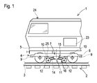
図1に略示する、レール3上を走行可能なレール走行装置4と、レール走行装置4上に支持された車両フレーム5とを備えた、軌道2の軌道形状を検出するための軌道検測車1は、慣性測定ユニット8および複数の位置測定装置9を備えている、走行装置フレーム6として形成された第1の測定基部7と、複数の第1の空圧駆動装置10を介して降下可能な第2の測定基部11とを有している。
A track inspection for detecting a track shape of a track 2 including a rail traveling device 4 that can travel on a
第2の測定基部11は、レール3に載置可能な複数の測定従輪12を有しており、かつ複数の連結棒14を介して第1の測定基部7に結合されている。連結棒14は、その上端部15において、回動可能に第1の測定基部7に支承されており、その下端部16において、それぞれ第1のテレスコープ軸17と第2のテレスコープ軸18とに結合されている。第1のテレスコープ軸17は、第2のテレスコープ軸18に対し、軌道車両長手方向軸線19を中心として回動可能に支承されている(図2)。
The
走行装置フレーム6上には複数のコンソール26が配置されていてよく、これらのコンソール26に第1の空圧駆動装置10が支持されている。つまり、既存のレール走行装置4に、コンソール26と、第1の測定基部7のフレームとを後付けすることが可能である。
A plurality of
軌道検測車1には、全球測位衛星システムの信号を受信するためのGNSSアンテナ24と、評価装置23とが配置されている。第2の測定基部11は、上昇位置では、好適には固定フックとして形成された複数の安全装置25によりロックされる。
The trajectory inspection vehicle 1 is provided with a
図2には、第1の測定基部7の一部と、降下された状態の第2の測定基部11とが示されている。レール走行装置4の端部側において、第1の測定基部7の下側に、複数の位置測定装置9が取り付けられている。これらの位置測定装置9は、好適にはレーザラインスキャナとして形成されており、この場合、各2つのレーザラインスキャナがレール3の内縁部に向けられている。
FIG. 2 shows a part of the
軌道中心における空間曲線を検出するために、第1の測定基部7には、慣性測定ユニット8が、好適には2つの位置測定装置9の間の真ん中に配置されている。つまり、第1の測定基部7は、走行装置フレーム6、位置測定装置9および慣性測定ユニット8と共に、1つの剛性の装置を形成している。第1の作動モードでは、レールに対する第1の測定基部7の位置が、位置測定装置9により連続的に検出される。
In order to detect the space curve at the center of the track, an inertial measuring unit 8 is arranged in the
第2の作動モードでは、第2の測定基部11が、第1の空圧駆動装置10により、軌道2上へ降下している。第1の空圧駆動装置10には、補償測定装置として、各1つの第1の距離測定装置20が配置されている。これにより、第1の測定基部7と第2の測定基部11との間の鉛直方向の相対移動が検出される。代わりに、相対移動を検出するためには連結棒14に角度測定装置が取り付けられていてもよい。
In the second operating mode, the
図3には、レール走行装置4を下から見た図が示されている。テレスコープ軸17,18には、測定従輪12をレール3に対して側方に圧着させるための第2の空圧駆動装置21が1つずつ配置されている。分岐器またはクロッシングを通過する際に測定従輪12がレールの隙間内へ押圧されることを防ぐために、各測定従輪12には案内支柱13が割り当てられている。案内支柱13がガードの傍らを案内されると直ちに、案内支柱13は割り当てられた測定従輪12を拘束し、このようにして圧着圧力に抗して作用する。
FIG. 3 shows a view of the rail traveling device 4 as viewed from below. On the
テレスコープ軸17,18の間の中間には、補償測定装置として第2の距離測定装置22が配置されており、第2の距離測定装置22は、第1の測定基部7に対する第2の測定基部11の横方向ずれを検出する。このようにして、第2の作動モードでは、機械的な補償測定装置20,22により、レール3に対する第1の測定基部7の位置が検出される。
In the middle between the telescope axes 17, 18 a second
1つの図示しない変化態様では、第1の測定基部7はレール走行装置4から分離され、フレームとしてレール車輪の車軸に取り付けられている。これにより、鉛直方向のレール延在部の直接的な測定作業が可能になると共に、レール3に対する第1の測定基部7の横方向の相対移動だけを検出すれば済むことになる。
In one variant, not shown, the
評価装置23には、慣性測定ユニット8、無接触式の位置測定装置9および補償測定装置20,22の測定信号が供給される。この場合、有利には連続的に、位置測定装置9の信号の妥当性点検が行われる。信号の飛躍または信号の異常が認められると直ちに第2の測定基部11が降下され、第1の作動モードから第2の作動モードに切り替えられる。
The
Claims (15)
降下可能な第2の測定基部(11)が配置されており、該第2の測定基部(11)は、前記レール(3)上に載置可能な測定従輪(12)を有しておりかつ補償測定装置(20,22)を介して前記第1の測定基部(7)に結合されていることを特徴とする、軌道検測車(1)。 A track inspection vehicle (1) for detecting a track shape of a track (2), capable of running on two rails (3) of a track (2) and having a rail running device (4). A vehicle frame (5) and a first measuring base (7) on which at least one contactless position measuring device (9) for position measurement with respect to the inertial measuring unit (8) and each rail (3) is arranged. In the track inspection car (1) equipped with
A descendable second measurement base (11) is arranged, said second measurement base (11) having a measurement follower (12) mountable on said rail (3); A track test vehicle (1), characterized in that it is coupled to said first measuring base (7) via compensation measuring devices (20, 22).
前記軌道検測車(1)の走行中に、前記慣性測定ユニット(8)によって空間曲線を検出し、第1の作動モードにおいて、前記位置測定装置(9)の測定データを用いて、前記空間曲線を、軌道延在部に対応する空間曲線に変換し、第2の作動モードにおいて、前記第2の測定基部(11)が降下した状態で、前記補償測定装置の測定データを用いて、前記空間曲線を、軌道延在部に対応する空間曲線に変換することを特徴とする、作動方法。 A method for operating a track inspection vehicle (1) according to any one of claims 1 to 13,
A space curve is detected by the inertial measurement unit (8) while the track inspection vehicle (1) is running, and in the first operation mode, the space is measured using the measurement data of the position measurement device (9). The curve is converted into a space curve corresponding to the track extension, and in the second operation mode, the second measurement base (11) is lowered and the measurement data of the compensation measurement device is used. An actuation method characterized by converting a space curve into a space curve corresponding to a track extension.
Applications Claiming Priority (3)
| Application Number | Priority Date | Filing Date | Title |
|---|---|---|---|
| ATA573/2016A AT519263B1 (en) | 2016-12-19 | 2016-12-19 | Track measuring vehicle and method for detecting a track geometry of a track |
| ATA573/2016 | 2016-12-19 | ||
| PCT/EP2017/080505 WO2018114233A1 (en) | 2016-12-19 | 2017-11-27 | Track-measuring vehicle and method for recording track geometry |
Publications (2)
| Publication Number | Publication Date |
|---|---|
| JP2020502402A true JP2020502402A (en) | 2020-01-23 |
| JP7086079B2 JP7086079B2 (en) | 2022-06-17 |
Family
ID=60515379
Family Applications (1)
| Application Number | Title | Priority Date | Filing Date |
|---|---|---|---|
| JP2019532995A Active JP7086079B2 (en) | 2016-12-19 | 2017-11-27 | Track inspection vehicle and method of detecting track shape |
Country Status (10)
| Country | Link |
|---|---|
| US (1) | US11827254B2 (en) |
| EP (1) | EP3554919B1 (en) |
| JP (1) | JP7086079B2 (en) |
| CN (1) | CN110087967B (en) |
| AT (1) | AT519263B1 (en) |
| CA (1) | CA3042136A1 (en) |
| EA (1) | EA036183B1 (en) |
| ES (1) | ES2835806T3 (en) |
| PL (1) | PL3554919T3 (en) |
| WO (1) | WO2018114233A1 (en) |
Cited By (2)
| Publication number | Priority date | Publication date | Assignee | Title |
|---|---|---|---|---|
| CN114559971A (en) * | 2022-03-03 | 2022-05-31 | 黄河水利职业技术学院 | Traffic monitoring equipment based on traffic Internet of things and monitoring method thereof |
| CN114812444A (en) * | 2022-04-27 | 2022-07-29 | 东风汽车集团股份有限公司 | Method for measuring trafficability parameter of automobile |
Families Citing this family (20)
| Publication number | Priority date | Publication date | Assignee | Title |
|---|---|---|---|---|
| AT519263B1 (en) * | 2016-12-19 | 2018-05-15 | Plasser & Theurer Export Von Bahnbaumaschinen Gmbh | Track measuring vehicle and method for detecting a track geometry of a track |
| FR3066770B1 (en) * | 2017-05-29 | 2019-07-26 | Matisa Materiel Industriel S.A. | PROCEDURE FOR ADJUSTING A GUIDE SYSTEM OF A RAIL WORKS MACHINE, METHOD AND SYSTEM FOR GUIDING THEM |
| US10807623B2 (en) | 2018-06-01 | 2020-10-20 | Tetra Tech, Inc. | Apparatus and method for gathering data from sensors oriented at an oblique angle relative to a railway track |
| CN109353370B (en) * | 2018-12-12 | 2023-11-10 | 湖南高创海捷工程技术有限公司 | Non-contact rail wave mill and contour detection device |
| AU2020273465C1 (en) | 2019-05-16 | 2026-02-05 | Tetra Tech, Inc. | System and method for generating and interpreting point clouds of a rail corridor along a survey path |
| CN110672026A (en) * | 2019-08-30 | 2020-01-10 | 泉州佰桀智能制鞋设备研究院有限公司 | Roller coaster track detection method, intelligent detection robot and detection system |
| DE102019133172B4 (en) * | 2019-12-05 | 2025-07-03 | Saf-Holland Gmbh | System and detection device for checking a condition of at least one component of a vehicle and method for checking a condition |
| CN110979399B (en) * | 2019-12-27 | 2021-09-28 | 郑州铁路职业技术学院 | Dynamic detection method for high-speed railway track condition |
| AT524207B1 (en) * | 2020-12-11 | 2022-04-15 | Siemens Mobility Austria Gmbh | Running gear for a rail vehicle |
| CN112832078B (en) * | 2021-01-25 | 2025-03-07 | 中铁十一局集团第四工程有限公司 | A railway line center inspection vehicle |
| CN113005865A (en) * | 2021-02-24 | 2021-06-22 | 江西通达检测技术开发有限公司 | Road engineering is with inside crack detection device of all-round highway |
| CN113619622A (en) * | 2021-07-30 | 2021-11-09 | 江西日月明测控科技股份有限公司 | Auxiliary guiding device and rail inspection equipment |
| JP2023142660A (en) * | 2022-03-25 | 2023-10-05 | 株式会社大林組 | Slide displacement measuring device |
| CN114991529B (en) * | 2022-05-30 | 2024-01-30 | 江苏鸿基节能新技术股份有限公司 | Integral translation device for building and construction method |
| CN115123336B (en) * | 2022-07-18 | 2023-04-25 | 郑州铁路职业技术学院 | An urban rail rail wave grinding fault detection device |
| CN115195810B (en) * | 2022-08-01 | 2024-01-30 | 北京交通大学 | Automatic lifting hook operation method and operation system in hump shunting and disassembling operation |
| CN116377777B (en) * | 2023-06-06 | 2023-08-08 | 中国科学院大学 | An acceptance device for railway tunnel construction based on BIM technology |
| CN116729900B (en) * | 2023-08-15 | 2023-10-24 | 山西精工天佑煤矿机械制造有限公司 | Scraper conveyor with tail coal cleaning structure |
| CN117802841B (en) * | 2024-02-27 | 2024-05-24 | 山东省住房和城乡建设发展研究院 | Angle measuring device for building track |
| CN117991278B (en) * | 2024-04-03 | 2024-06-18 | 任丘市东之风专用量仪有限公司 | Digital signal acquisition intelligent system and device of measuring instrument based on big data |
Citations (6)
| Publication number | Priority date | Publication date | Assignee | Title |
|---|---|---|---|---|
| JPS51101561A (en) * | 1975-03-05 | 1976-09-08 | Japan National Railway | Kogakushikikidokuruisokuteisochi |
| US5199176A (en) * | 1990-11-12 | 1993-04-06 | Franz Plasser Bahnbaumaschinen-Industriegesellschaft M.B.H. | Apparatus for the non-contact measurement of a track gage |
| JPH08122042A (en) * | 1994-10-13 | 1996-05-17 | Fiat Ferroviaria Spa | Apparatus and method for detecting relative position between vehicle tracks |
| JPH10339629A (en) * | 1997-06-10 | 1998-12-22 | Nikon Corp | Measuring device |
| JP2003237576A (en) * | 2002-02-12 | 2003-08-27 | Hitachi Electronics Eng Co Ltd | Towed track inspection vehicle |
| JP2016061630A (en) * | 2014-09-17 | 2016-04-25 | 三菱電機株式会社 | Gauge measuring device, gauge measuring method |
Family Cites Families (27)
| Publication number | Priority date | Publication date | Assignee | Title |
|---|---|---|---|---|
| US4654973A (en) * | 1985-10-21 | 1987-04-07 | Worthy James T | Railroad track gage |
| DE3914830C3 (en) * | 1989-02-06 | 1996-01-11 | Gewerk Schalker Eisenhuette | Track measuring device |
| AT402519B (en) | 1990-02-06 | 1997-06-25 | Plasser Bahnbaumasch Franz | CONTINUOUSLY RIDABLE RAILWAY MACHINE FOR COMPRESSING THE GRAVEL BED OF A TRACK |
| FR2662984B1 (en) * | 1990-06-12 | 1992-07-31 | Cegelec | VEHICLE ON TRACKS FOR MEASUREMENT OF GEOMETRIC TRACK PARAMETERS. |
| US7164975B2 (en) | 1999-06-15 | 2007-01-16 | Andian Technologies Ltd. | Geometric track and track/vehicle analyzers and methods for controlling railroad systems |
| US6725782B1 (en) * | 2003-03-24 | 2004-04-27 | Franz Plasser Bahnbaumaschinen-Industriegesellschaft M.B.H | Railroad test vehicle comprising a railroad measurement axle suspension |
| WO2008122319A1 (en) | 2007-04-05 | 2008-10-16 | Siemens Transportation Systems Gmbh & Co. Kg | Measuring arrangement for the contactless and continuous determination of routing and track layout of railroad tracks |
| AT505029B1 (en) * | 2007-07-31 | 2008-10-15 | Plasser Bahnbaumasch Franz | METHOD FOR MEASURING A TRAIL STATION |
| US9810533B2 (en) * | 2011-04-27 | 2017-11-07 | Trimble Inc. | Railway track monitoring |
| CN202298394U (en) | 2011-10-19 | 2012-07-04 | 北京鼎汉检测技术有限公司 | Detection system for dynamically detecting track gauge of railway track |
| DE102013210361A1 (en) * | 2013-06-04 | 2014-12-04 | Siemens Aktiengesellschaft | Method for determining at least one speed in a rail vehicle |
| US9459624B2 (en) * | 2013-07-08 | 2016-10-04 | Mega Trax Corporation | Semi-autonomous dolly |
| AT517345B1 (en) * | 2015-06-17 | 2017-01-15 | Plasser & Theurer Export Von Bahnbaumaschinen Gmbh | Track construction machine for the implementation of track position corrections |
| AT518579B1 (en) * | 2016-04-15 | 2019-03-15 | Plasser & Theurer Export Von Bahnbaumaschinen Gmbh | Method and measuring system for detecting a fixed point next to a track |
| CN106092056B (en) | 2016-06-28 | 2018-07-13 | 中国人民解放军国防科学技术大学 | A kind of vehicle-mounted dynamic monitoring method of high-speed railway bridge foundation settlement deformation |
| AT518839B1 (en) * | 2016-07-11 | 2018-12-15 | Plasser & Theurer Exp Von Bahnbaumaschinen G M B H | System and method for measuring a track |
| AT519316B1 (en) * | 2016-11-04 | 2019-05-15 | Plasser & Theurer Export Von Bahnbaumaschinen Gmbh | Track construction machine with track position measuring system |
| AT519003B1 (en) * | 2016-12-19 | 2018-03-15 | Plasser & Theurer Export Von Bahnbaumaschinen Gmbh | Measuring device and method for detecting a track geometry |
| AT519263B1 (en) * | 2016-12-19 | 2018-05-15 | Plasser & Theurer Export Von Bahnbaumaschinen Gmbh | Track measuring vehicle and method for detecting a track geometry of a track |
| AT519088B1 (en) * | 2017-02-07 | 2018-04-15 | Plasser & Theurer Export Von Bahnbaumaschinen Gmbh | Method for the contactless detection of a track geometry |
| AT519575B1 (en) * | 2017-02-15 | 2018-08-15 | Plasser & Theurer Export Von Bahnbaumaschinen Gmbh | Track measuring vehicle and method for detecting a vertical track position |
| EP3601006A4 (en) * | 2017-03-27 | 2021-04-28 | Harsco Technologies LLC | Track geometry measurement system with inertial measurement |
| AT520526B1 (en) * | 2018-02-02 | 2019-05-15 | Plasser & Theurer Export Von Bahnbaumaschinen Gmbh | Rail vehicle and method for measuring a track section |
| AT520291B1 (en) * | 2018-06-01 | 2019-03-15 | Plasser & Theurer Export Von Bahnbaumaschinen Gmbh | Method for determining an actual position of rails of a track |
| AT521263B1 (en) * | 2018-08-20 | 2019-12-15 | Hp3 Real Gmbh | Individual troubleshooting procedure |
| AT522764B1 (en) * | 2019-08-29 | 2021-01-15 | Plasser & Theurer Export Von Bahnbaumaschinen Gmbh | Method and measuring vehicle for determining the actual position of a track |
| AT17358U1 (en) * | 2019-12-16 | 2022-02-15 | Plasser & Theurer Export Von Bahnbaumaschinen Gmbh | Method and monitoring system for determining a position of a rail vehicle |
-
2016
- 2016-12-19 AT ATA573/2016A patent/AT519263B1/en active
-
2017
- 2017-11-27 WO PCT/EP2017/080505 patent/WO2018114233A1/en not_active Ceased
- 2017-11-27 CN CN201780078556.4A patent/CN110087967B/en active Active
- 2017-11-27 US US16/464,786 patent/US11827254B2/en active Active
- 2017-11-27 EP EP17807822.6A patent/EP3554919B1/en active Active
- 2017-11-27 EA EA201900207A patent/EA036183B1/en not_active IP Right Cessation
- 2017-11-27 JP JP2019532995A patent/JP7086079B2/en active Active
- 2017-11-27 CA CA3042136A patent/CA3042136A1/en active Pending
- 2017-11-27 PL PL17807822T patent/PL3554919T3/en unknown
- 2017-11-27 ES ES17807822T patent/ES2835806T3/en active Active
Patent Citations (6)
| Publication number | Priority date | Publication date | Assignee | Title |
|---|---|---|---|---|
| JPS51101561A (en) * | 1975-03-05 | 1976-09-08 | Japan National Railway | Kogakushikikidokuruisokuteisochi |
| US5199176A (en) * | 1990-11-12 | 1993-04-06 | Franz Plasser Bahnbaumaschinen-Industriegesellschaft M.B.H. | Apparatus for the non-contact measurement of a track gage |
| JPH08122042A (en) * | 1994-10-13 | 1996-05-17 | Fiat Ferroviaria Spa | Apparatus and method for detecting relative position between vehicle tracks |
| JPH10339629A (en) * | 1997-06-10 | 1998-12-22 | Nikon Corp | Measuring device |
| JP2003237576A (en) * | 2002-02-12 | 2003-08-27 | Hitachi Electronics Eng Co Ltd | Towed track inspection vehicle |
| JP2016061630A (en) * | 2014-09-17 | 2016-04-25 | 三菱電機株式会社 | Gauge measuring device, gauge measuring method |
Cited By (3)
| Publication number | Priority date | Publication date | Assignee | Title |
|---|---|---|---|---|
| CN114559971A (en) * | 2022-03-03 | 2022-05-31 | 黄河水利职业技术学院 | Traffic monitoring equipment based on traffic Internet of things and monitoring method thereof |
| CN114559971B (en) * | 2022-03-03 | 2023-02-24 | 黄河水利职业技术学院 | Traffic monitoring equipment based on traffic Internet of things and monitoring method thereof |
| CN114812444A (en) * | 2022-04-27 | 2022-07-29 | 东风汽车集团股份有限公司 | Method for measuring trafficability parameter of automobile |
Also Published As
| Publication number | Publication date |
|---|---|
| PL3554919T3 (en) | 2021-04-19 |
| EP3554919A1 (en) | 2019-10-23 |
| AT519263A4 (en) | 2018-05-15 |
| JP7086079B2 (en) | 2022-06-17 |
| US20190344813A1 (en) | 2019-11-14 |
| CN110087967A (en) | 2019-08-02 |
| EA201900207A1 (en) | 2019-11-29 |
| EA036183B1 (en) | 2020-10-12 |
| US11827254B2 (en) | 2023-11-28 |
| AT519263B1 (en) | 2018-05-15 |
| ES2835806T3 (en) | 2021-06-23 |
| CN110087967B (en) | 2020-10-16 |
| EP3554919B1 (en) | 2020-10-21 |
| WO2018114233A1 (en) | 2018-06-28 |
| CA3042136A1 (en) | 2018-06-28 |
Similar Documents
| Publication | Publication Date | Title |
|---|---|---|
| JP2020502402A (en) | Track inspection vehicle and method of detecting track shape | |
| CN110249095B (en) | Method for non-contact detection of track geometry | |
| KR101827485B1 (en) | Trolly apparatus for measuring track irregularity having track guidance member of hydraulic type, and method for the same | |
| JP7146814B2 (en) | Track Inspection Vehicles and Methods for Detecting Vertical Track Position | |
| KR102712220B1 (en) | How to measure railway vehicles and track sections | |
| KR101840729B1 (en) | Trolly apparatus for measuring track irregularity having clinometer and insulation device on troll plate | |
| EP1774275B1 (en) | Apparatus for detecting hunting and angle of attack of a rail vehicle wheelset | |
| KR101590712B1 (en) | Rail car and track monitoring system using running record and the method | |
| KR20170041169A (en) | Obstacle and derailment detection device for a railway vehicle | |
| JP2020502401A (en) | Inspection apparatus and method for detecting track shape | |
| CN107074255B (en) | Apparatus and method for determining at least one characteristic of a track for a rail vehicle and rail vehicle | |
| KR101619790B1 (en) | Method and system for detecting an abrasion of wheel in train | |
| CN106794852B (en) | Device and method for detecting a vehicle environment of a rail vehicle and a rail vehicle | |
| CN107921976B (en) | Detection device and method for monitoring a defined limit of a train of vehicles, in particular rail vehicles | |
| KR101648340B1 (en) | Device for detecting the position of the railway vehicle and hence the method | |
| JP3017459B2 (en) | A device for measuring the deviation of the wheels of railway vehicles | |
| JP5931535B2 (en) | Inspection vehicle shake state correction method and apparatus, and inspection method and apparatus | |
| JP6770414B2 (en) | Ride comfort measurement method and equipment | |
| JP5802560B2 (en) | Inspection vehicle shake correction method and apparatus, and inspection method and apparatus | |
| KR102900939B1 (en) | Railway Vehicle Speed and Position Measurement System Using Single Accelerometer and GPS, Method for Measuring Railway Vehicle Speed and Position Using the Same | |
| US20090094848A1 (en) | Track Twist Monitoring | |
| JP2013241113A (en) | Method and device for correcting shake of inspection vehicle, measurement method and device | |
| RU2442714C1 (en) | Control unit for gage width | |
| EA041026B1 (en) | METHOD FOR CONTINUOUS NON-CONTACT REGISTRATION OF RAIL TRACK GEOMETRY AND DEVICE FOR CONTINUOUS NON-CONTACT REGISTRATION OF RAIL TRACK GEOMETRY | |
| JP2005104449A (en) | Track measuring device |
Legal Events
| Date | Code | Title | Description |
|---|---|---|---|
| A621 | Written request for application examination |
Free format text: JAPANESE INTERMEDIATE CODE: A621 Effective date: 20201127 |
|
| A977 | Report on retrieval |
Free format text: JAPANESE INTERMEDIATE CODE: A971007 Effective date: 20211022 |
|
| A131 | Notification of reasons for refusal |
Free format text: JAPANESE INTERMEDIATE CODE: A131 Effective date: 20211108 |
|
| A521 | Request for written amendment filed |
Free format text: JAPANESE INTERMEDIATE CODE: A523 Effective date: 20220127 |
|
| TRDD | Decision of grant or rejection written | ||
| A01 | Written decision to grant a patent or to grant a registration (utility model) |
Free format text: JAPANESE INTERMEDIATE CODE: A01 Effective date: 20220530 |
|
| A61 | First payment of annual fees (during grant procedure) |
Free format text: JAPANESE INTERMEDIATE CODE: A61 Effective date: 20220607 |
|
| R150 | Certificate of patent or registration of utility model |
Ref document number: 7086079 Country of ref document: JP Free format text: JAPANESE INTERMEDIATE CODE: R150 |
|
| R250 | Receipt of annual fees |
Free format text: JAPANESE INTERMEDIATE CODE: R250 |
|
| R250 | Receipt of annual fees |
Free format text: JAPANESE INTERMEDIATE CODE: R250 |