JP2020512935A - Daigast machine with automatic air purge system - Google Patents
Daigast machine with automatic air purge system Download PDFInfo
- Publication number
- JP2020512935A JP2020512935A JP2019545321A JP2019545321A JP2020512935A JP 2020512935 A JP2020512935 A JP 2020512935A JP 2019545321 A JP2019545321 A JP 2019545321A JP 2019545321 A JP2019545321 A JP 2019545321A JP 2020512935 A JP2020512935 A JP 2020512935A
- Authority
- JP
- Japan
- Prior art keywords
- valve
- injection
- amplification
- piston
- main
- Prior art date
- Legal status (The legal status is an assumption and is not a legal conclusion. Google has not performed a legal analysis and makes no representation as to the accuracy of the status listed.)
- Granted
Links
Images
Classifications
-
- B—PERFORMING OPERATIONS; TRANSPORTING
- B22—CASTING; POWDER METALLURGY
- B22D—CASTING OF METALS; CASTING OF OTHER SUBSTANCES BY THE SAME PROCESSES OR DEVICES
- B22D17/00—Pressure die casting or injection die casting, i.e. casting in which the metal is forced into a mould under high pressure
- B22D17/20—Accessories: Details
- B22D17/2015—Means for forcing the molten metal into the die
-
- B—PERFORMING OPERATIONS; TRANSPORTING
- B22—CASTING; POWDER METALLURGY
- B22D—CASTING OF METALS; CASTING OF OTHER SUBSTANCES BY THE SAME PROCESSES OR DEVICES
- B22D17/00—Pressure die casting or injection die casting, i.e. casting in which the metal is forced into a mould under high pressure
- B22D17/20—Accessories: Details
- B22D17/32—Controlling equipment
-
- B—PERFORMING OPERATIONS; TRANSPORTING
- B22—CASTING; POWDER METALLURGY
- B22D—CASTING OF METALS; CASTING OF OTHER SUBSTANCES BY THE SAME PROCESSES OR DEVICES
- B22D17/00—Pressure die casting or injection die casting, i.e. casting in which the metal is forced into a mould under high pressure
- B22D17/08—Cold chamber machines, i.e. with unheated press chamber into which molten metal is ladled
- B22D17/10—Cold chamber machines, i.e. with unheated press chamber into which molten metal is ladled with horizontal press motion
-
- B—PERFORMING OPERATIONS; TRANSPORTING
- B22—CASTING; POWDER METALLURGY
- B22D—CASTING OF METALS; CASTING OF OTHER SUBSTANCES BY THE SAME PROCESSES OR DEVICES
- B22D17/00—Pressure die casting or injection die casting, i.e. casting in which the metal is forced into a mould under high pressure
- B22D17/20—Accessories: Details
- B22D17/2015—Means for forcing the molten metal into the die
- B22D17/203—Injection pistons
Landscapes
- Engineering & Computer Science (AREA)
- Mechanical Engineering (AREA)
- Injection Moulding Of Plastics Or The Like (AREA)
- Casting Devices For Molds (AREA)
Abstract
ダイカストマシンの噴射アセンブリ(1)は、噴射ピストン(20)と増幅ピストン(42)の前進及び戻りを制御する弁手段を備える。弁手段は、比例送達弁(104)、比例噴射排出弁(112)及び比例増幅弁(118)を含む複数の弁を備える。弁の開閉を予め決められた回数だけ交互に行うエアパージサイクルを実行するように構成及び/又はプログラムされた電子制御手段(300)を備える。【選択図】図1The injection assembly (1) of the die casting machine comprises valve means for controlling the advancement and return of the injection piston (20) and the amplification piston (42). The valve means comprises a plurality of valves including a proportional delivery valve (104), a proportional injection discharge valve (112) and a proportional amplification valve (118). Electronic control means (300) configured and / or programmed to perform an air purge cycle in which the valves are alternately opened and closed a predetermined number of times. [Selection diagram] Figure 1
Description
本発明は、特に軽合金の鋳造のための液圧制御を備えたダイカストマシンに関する。具体的には、本発明は、噴射プロセスを制御するための弁を備え、弁からの自動エアパージシステムを備えたダイカストマシンの噴射アセンブリに関する。 The present invention relates to a die casting machine with hydraulic control, especially for the casting of light alloys. Specifically, the present invention relates to a die casting machine injection assembly that includes a valve for controlling the injection process and that includes an automatic air purge system from the valve.
周知のように、これらのマシンは、製造される部品に対応するキャビティを形成するように連結可能な2つの半型を備える金型で動作し、金型用の閉塞アセンブリと、溶融金属を金型内に押し込むために噴射ピストンを備える噴射アセンブリとを備えている。 As is well known, these machines operate on a mold that includes two halves that can be joined to form a cavity that corresponds to the part being manufactured, and a closure assembly for the mold and a molten metal mold. And an injection assembly with an injection piston for pushing into the mold.
噴射ピストンの動作及び更なるプロセス制御の作動のために、複数の弁によって調整される液圧回路が設けられている。 A hydraulic circuit regulated by a plurality of valves is provided for actuation of the injection piston and actuation of further process control.
メンテナンス作業中において、幾つかの弁は、マシンから分解され、洗浄され、再び取り付けられる。しかしながら、必要に応じて、それらは新しい弁と交換される。 During maintenance operations, some valves are disassembled from the machine, cleaned and reattached. However, if necessary, they are replaced with new valves.
その結果、これらの弁内には、エアポケットが発見される。エアポケットは、弁自体の正しい動作のために排出される必要がある。 As a result, air pockets are found in these valves. The air pocket needs to be evacuated for proper operation of the valve itself.
現在、これらのポケットの排出には、手動介入が必要である。これは、弁への物理的アクセスを意味し、非常に多くの場合、容易ではなく、いくつかの動作の実行を意味する。 Evacuation of these pockets currently requires manual intervention. This means physical access to the valve, very often not easy, and means performing some actions.
本発明の目的は、弁の自動エアパージシステムを備えた液圧駆動式のダイカストマシンを提供することにある。 An object of the present invention is to provide a hydraulically driven die casting machine equipped with an automatic air purge system for valves.
前記目的は、請求項1によって実施されるダイカストマシンにより達成される。従属請求項は、本発明の更なる実施形態を説明する。
The object is achieved by a die casting machine embodied by
本発明に係るダイカストマシンの特徴及び利点は、以下の図を参照して、例示的且つ非限定的な例として行われる以下の説明からより明確に明らかになるであろう。
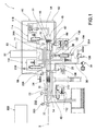
図1を参照すると、参照符号1は、全体として、液圧駆動装置を備えたダイカストマシンの噴射アセンブリを示している。
Referring to FIG. 1,
噴射アセンブリ1は、頭部22とその反対側の端部24との間の並進軸Xに沿って延在する噴射ピストン20を備えている。噴射ピストン20は、液圧駆動装置によって並進軸Xに沿って移動することができる。
The
また、噴射アセンブリ1は、噴射ピストン20の出口で並進する流体を収容及び押圧するため、噴射ピストン20の上流、すなわちその端部24の上流に、メイン圧力室26を有している。
The
噴射アセンブリ1は、更に、メイン流体入口部28と、メイン流体入口部28とメイン圧力室26との間に配置され且つメイン圧力室26からメイン流体入口部28への流体の戻りを防止するように構成された逆止弁102とを備えている。
The
例えば、逆止弁102は、出願人に代わって文献EP−A1−2942127号に含まれる教示に従って実施される。
For example, the
ダイカストマシンは、更に、噴射ピストン20の制御回路用の(例えば、圧力下の窒素を含む対応するシリンダから充填することができる)第1アキュムレータ30を備えている。第1アキュムレータ30は、メイン流体入口部28の上流に接続されている。比例送達弁104は、第1アキュムレータ30とメイン流体入口部28との間で作動する。
The die casting machine further comprises a
送達弁104は、電子的に制御され、位置検出器204を介したフィードバックを有している。位置検出器204は、弁の開度に応じて信号を検出するように構成されている。
また、メイン圧力室26は、排出部に接続された噴射排出部29に接続され、それらの間で噴射排出逆止弁105が作動する。
Further, the
噴射アセンブリ1は、更に、噴射ピストン20の端部24の下流にメイン背圧室32を備えている。メイン背圧室32は、噴射ピストン20の戻り並進のための加圧流体を供給する戻り入口部34に接続されている。
The
戻り入口部34は、ポンプ送達部36に上流で接続されている。ポンプ送達部36の上流には、典型的には電気モータによって駆動されるポンプ38が配置されている。
The
噴射逆止弁106は、ポンプ送達部36と戻り入口部34との間に配置されている。
The
更に、ポンプ38の出口における圧力を調整するために、比例ポンプ最大圧力弁108がポンプ送達部36から分岐して配置され、排出部に接続されている。
Further, a proportional pump
メイン背圧室32は、更に、排出部に接続された戻り排出部40に接続され、それらの間に比例噴射排出弁112が、配置され、電子制御され、且つ、弁の開放の機能として信号を発するように構成された位置検出器212を備えている。
The main
噴射アセンブリ1は、更に、メイン圧力室26に収容される流体の圧力を第1アキュムレータ30によって供給される圧力よりも高くするように構成された圧力増幅手段を備えている。
The
圧力増幅手段は、メイン圧力室26内にて圧縮状態で作動するように構成された頭部44とその反対側の端部46との間において、例えば噴射ピストン20の並進軸Xと一致する増幅軸Yに沿って延在する増幅ピストン42を備えている。
The pressure amplifying means is, for example, between the
増幅ピストン42は、増幅軸Yに沿ったコマンドで並進可能である。
The
圧力増幅手段は、更に、増幅ピストン42の上流の二次圧力室48と、加圧下の流体の入口のための、二次圧力室48の上流の二次流体入口部50とを備えている。
The pressure amplification means further comprises a
ダイカストマシンは、更に、二次流体入口部50に接続可能な(相対補充シリンダ付き)第2アキュムレータ52を備えている。第2アキュムレータ52と二次流体入口部50との間には、増幅開放弁114が配置されている。
The die casting machine further comprises a second accumulator 52 (with a relative refill cylinder) connectable to the
また、二次圧力室48は、排出部に接続された増幅戻り排出部54にも接続され、それらの間に増幅排出逆止弁116が配置されている。
The
更に、圧力増幅手段は、増幅ピストン42の端部46の下流に二次背圧室56を備えている。二次背圧室56は、二次背圧入口部58を介して第2アキュムレータ52に接続可能である。
Further, the pressure amplification means includes a secondary
二次背圧入口部58に沿って、第2アキュムレータ52と二次背圧室56との間で、比例メイン増幅弁118が、作動し、電子制御可能であり、且つ、弁の開放の機能として信号を発するように構成された位置検出器218を備えている。
Along the secondary
最後に、第1補助セクション60が、増幅排出逆止弁116をメイン増幅弁118に接続するとともに、排出部に配置されている。第2セクション62が、増幅排出逆止弁116を噴射排出逆止弁105に接続する。
Finally, the first
更に、噴射アセンブリ1は、
噴射ピストン20の位置を検出するためのエンコーダなど噴射ピストン位置センサ222と、
メイン背圧室32内の圧力を検出するためのメイン背圧室圧力変換器232と、
メイン圧力室26内の圧力を検出するためのメイン室圧力変換器226と、
二次背圧室56内の圧力を検出するための二次背圧室圧力変換器256と、
を備えている。
Furthermore, the
An injection
A main back pressure
A main
A secondary back pressure
Is equipped with.
ダイカストプロセスは、溶融金属が金型に設けられた付属チャネルを充填できるようにするために、噴射ピストン20が低速で前進する第1噴射ステップを提供する。
The die casting process provides a first injection step in which the
第1噴射ステップでは、送達弁104の制御された部分的開放のために、加圧流体が、例えば150バールの公称圧力でメイン流体入口部28に供給され、逆止弁102の開放の結果としてここからメイン圧力室26に送られる。
In the first injection step, pressurized fluid is supplied to the main
噴射排出弁112の制御された開放により、メイン背圧室32が排出部にセットされ、メイン圧力室26内の流体の作用とメイン背圧室32内の流体の反作用とが、所望の速度での噴射ピストン20の出力の推力を生成する。
By the controlled opening of the injection and
その後、ダイカストプロセスは、好ましくは前のステップで中断することなく、噴射ピストン20が第1噴射ステップの前進速度よりも速い速度で前進する第2噴射ステップを提供する。
The die casting process then provides a second injection step in which the
第2噴射ステップでは、送達弁104の更なる制御された開放により、例えば全体に対して、加圧流体が、より大きな流量でメイン流体入口部28に供給され、逆止弁102の開放の結果としてそこからメイン圧力室26に供給される。
In the second injection step, a further controlled opening of the
更に、好ましくは、噴射排出弁112の更なる制御された開放により、メイン背圧室32が排出部にセットされ、メイン圧力室30内の流体の作用とメイン背圧室32内の流体の反作用とが、所望の高速での噴射ピストン20の出力の推力を生成する。
Further, preferably, further controlled opening of the injection and
その後、ダイカストプロセスは、好ましくは前のステップで中断することなく、噴射ピストンの速度はほぼゼロであるが、溶融金属に高い推力を加えて、冷却による収縮を回復するように凝固中の溶融金属を強制する第3噴射ステップを提供する。 Then, the die casting process is preferably uninterrupted in the previous step, the velocity of the injection piston is almost zero, but high thrust is applied to the molten metal to restore the shrinkage due to cooling to recover the molten metal during solidification. A third injection step that forces the
第3噴射ステップでは、圧力増幅手段が作動する。 In the third injection step, the pressure amplification means operates.
具体的には、増幅開放弁114の制御された開放にしたがって、加圧流体が、二次流体入口部50に供給され、そこから二次圧力室48に供給される。二次背圧室56には、制御された態様でメイン増幅弁118を通じて加圧流体が供給され、増幅ピストン42が、メイン圧力室26内に存在する流体に推力作用を及ぼし、その圧力を例えば最大500バールまで増加させる。
Specifically, according to the controlled opening of the
この結果として、メイン流体入口部28とメイン圧力室26との間の圧力差に敏感な逆止弁102が、閉塞構造に切り替わり、メイン流体入口部28とメイン圧力室26とを流体的に分離する。
As a result, the
高圧にされたメイン圧力室26内の流体は、噴射ピストン20に作用し、噴射ピストン20が、金型内の金属に所望の収縮の回復作用を及ぼす。
The high-pressure fluid in the
第3噴射ステップが終了すると、圧力増幅手段が停止する。具体的には、増幅ピストン42が、増圧排出逆止弁116の開放により、二次背圧室56及び二次圧力室48の排出接続部に供給される加圧流体によって戻り行程を行う。
When the third injection step ends, the pressure amplification means stops. Specifically, the
更に、噴射ピストン20は、噴射逆止弁106を開放することにより、戻り入口部34及びポンプ送達部36を介してメイン背圧室32に供給されるとともに、噴射逆止弁105を開放するためにメイン圧力室26の排出部との接続部に供給される加圧流体によって、戻りストロークを実行する。
Further, the
ダイカストマシンは、例えば、電子制御ユニット又はプログラム可能なPLC又はマイクロプロセッサを有する制御手段300を更に備えている。制御手段300は、前記センサ及び/又は前記検出器によって出射される信号の機能として、及び/又は所定の制御プログラムの機能として前記弁の開閉を制御するために、前記弁及び/又は前記センサ及び/又は前記検出器と動作可能に接続されている。 The die-casting machine further comprises control means 300, which comprises, for example, an electronic control unit or a programmable PLC or microprocessor. The control means 300 controls the opening and closing of the valve as a function of the signal emitted by the sensor and / or the detector and / or as a function of a predetermined control program. And / or operably connected to the detector.
本発明によれば、ダイカストマシンは、前記制御プログラムによって動作する自動パージシステムを備え、弁の弁本体に含まれるエアポケットが排出される間にパージサイクルを実行する。 According to the present invention, the die casting machine includes an automatic purge system that operates according to the control program, and executes the purge cycle while the air pockets included in the valve body of the valve are discharged.
前記パージサイクルは、好ましくは完全な態様で、弁の開閉を交互に複数回実行することを提供する。 The purging cycle provides for alternating multiple opening and closing of valves, preferably in a complete manner.
このようにして、例えば分配引出し(distribution drawer)などのメイン弁要素の交互の反復運動により、弁本体の内部の空洞から空気を排出する効果が生じる。 In this way, alternating repetitive movements of the main valve element, such as a distribution drawer, have the effect of expelling air from the cavity inside the valve body.
好ましくは、空気は、弁本体を出てドレン又はオイルタンクに向かう流体とともに除去される。
送達弁のパージサイクル
Preferably, the air is removed with the fluid exiting the valve body towards the drain or oil tank.
Delivery valve purge cycle
本発明の一実施形態によれば、パージシステムは、送達弁104のパージサイクルの実行を提供する。
According to one embodiment of the invention, the purge system provides for performing a purge cycle of
前記送達弁のパージサイクルは、送達弁のパージの実行のための初期条件をチェックする初期ステップを提供する。 The delivery valve purge cycle provides an initial step of checking initial conditions for performing a delivery valve purge.
例えば、上記の初期条件は、以下の通りである。
1)噴射排出弁112がイネーブル=オン及び制御電圧=0ボルト
2)送達弁104がイネーブル=オン及び制御電圧=0ボルト
3)メイン増幅弁118がイネーブル=オン及び制御電圧=0ボルト
4)噴射排出弁112からのフィードバック<閾値、すなわち、前記弁が閉塞
5)送達弁104からのフィードバック<閾値、すなわち、前記弁が閉塞
6)閾値間におけるメイン増幅弁118からのフィードバック、すなわち、前記弁が閉塞
7)増幅開放弁114が無制御
8)噴射戻り送達弁105が無制御、すなわち、送達室が排出される
9)噴射戻り弁106が無制御
10)増幅戻り排出弁116がオフ、すなわち、頭部側の室が排出される
11)送達圧力(メイン室圧力変換器226により測定)<閾値、すなわち、メイン圧力室26に圧力がない
12)噴射ピストン20が後退限界位置
13)噴射エリアにアクセスするための安全ドアが閉塞
For example, the above initial conditions are as follows.
1)
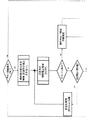
初期条件が満たされた場合、パージサイクルは、送達弁104を所定の回数、交互に、開放(好ましくは完全に)及び閉塞(好ましくは完全に)する作動パージサイクルを実行する。 If the initial conditions are met, the purge cycle performs an actuated purge cycle that alternately opens (preferably completely) and closes (preferably completely) the delivery valve 104 a predetermined number of times.
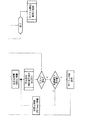
具体的には、この動作サイクルは、図2a及び図2bのフローチャートに従って動作する。
噴射排出弁のパージサイクル
Specifically, this operation cycle operates according to the flowcharts of FIGS. 2a and 2b.
Injection and discharge valve purge cycle
本発明の更なる実施形態によれば、パージシステムは、噴射排出弁112のパージサイクルの実行を提供する。
According to a further embodiment of the invention, the purge system provides for performing a purge cycle of the
前記送達弁のパージサイクルは、噴射排出弁のパージの実行のための初期条件をチェックする初期ステップを提供する。 The delivery valve purge cycle provides an initial step of checking the initial conditions for performing the injection exhaust valve purge.
例えば、上記の初期条件は、以下の通りである。
1)噴射排出弁112がイネーブル=オン及び制御電圧=0ボルト
2)送達弁104がイネーブル=オン及び制御電圧=0ボルト
3)メイン増幅弁118がイネーブル=オン及び制御電圧=0ボルト
4)噴射排出弁112からのフィードバック<閾値、すなわち、前記弁が閉塞
5)送達弁104からのフィードバック<閾値、すなわち、前記弁が閉塞
6)閾値間におけるメイン増幅弁118からのフィードバック、すなわち、前記弁が閉塞
7)増幅開放弁114が無制御
8)噴射戻り送達弁105が無制御、すなわち、送達室が排出される
9)噴射戻り弁106が無制御
10)増幅戻り排出弁116がオフ、すなわち、頭部側の室が排出される
11)送達圧力(メイン室圧力変換器226により測定)<閾値、すなわち、メイン圧力室26に圧力がない。
12)噴射ピストン20が後退限界位置
13)噴射エリアにアクセスするための安全ドアが閉塞
For example, the above initial conditions are as follows.
1)
12)
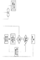
初期条件が満たされた場合、パージサイクルは、噴射排出弁112を所定の回数、交互に、開放(好ましくは完全に)及び閉塞(好ましくは完全に)する作動パージサイクルを実行する。 If the initial conditions are met, the purge cycle performs an operating purge cycle that alternately opens (preferably completely) and closes (preferably completely) the injection and exhaust valve 112 a predetermined number of times.
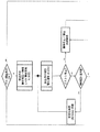
具体的には、この動作サイクルは、図3a及び図3bのフローチャートに従って動作する。
メイン増幅弁のパージサイクル
Specifically, this operation cycle operates according to the flowcharts of FIGS. 3a and 3b.
Main amplification valve purge cycle
本発明の更なる実施形態によれば、パージシステムは、噴射排出弁118のパージサイクルの実行を提供する。
According to a further embodiment of the invention, the purge system provides for performing a purge cycle of the
前記メイン増幅弁のパージサイクルは、メイン増幅弁のパージの実行のための初期条件をチェックする初期ステップを提供する。 The main amplification valve purge cycle provides an initial step of checking initial conditions for performing a main amplification valve purge.
例えば、上記の初期条件は、以下の通りである。
1)噴射排出弁112がイネーブル=オン及び制御電圧=0ボルト
2)送達弁104がイネーブル=オン及び制御電圧=0ボルト
3)メイン増幅弁118がイネーブル=オン及び制御電圧=0ボルト
4)噴射排出弁112からのフィードバック<閾値、すなわち、前記弁が閉塞
5)送達弁104からのフィードバック<閾値、すなわち、前記弁が閉塞
6)閾値間におけるメイン増幅弁118からのフィードバック、すなわち、前記弁が閉塞
7)増幅開放弁114が無制御
8)噴射戻り送達弁105が無制御、すなわち、送達室が排出される
9)噴射戻り弁106が無制御
10)増幅戻り排出弁116がオフ、すなわち、頭部側の室が排出される
11)送達圧力(メイン室圧力変換器226により測定)<閾値、すなわち、メイン圧力室26に圧力がない
12)噴射ピストン20が後退限界位置
13)噴射エリアにアクセスするための安全ドアが閉塞
For example, the above initial conditions are as follows.
1)
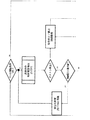
初期条件が満たされた場合、パージサイクルは、メイン増幅弁118を所定の回数、交互に、開放(好ましくは完全に)及び閉塞(好ましくは完全に)する作動パージサイクルを実行する。 If the initial conditions are met, the purge cycle performs a working purge cycle of opening (preferably completely) and closing (preferably completely) the main amplification valve 118 a predetermined number of times, alternately.
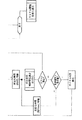
具体的には、この動作サイクルは、図4a及び図4bのフローチャートに従って動作する。
--o--
Specifically, this operation cycle operates according to the flowcharts of FIGS. 4a and 4b.
--o--
更に、制御手段300は、例えば、各サイクルの結果を表示するためのスクリーン又はディスプレイを含む表示手段を備え、サイクルの正確な実行又はサイクルの不正確な実行又は不可能を強調表示する。 Furthermore, the control means 300 comprises display means, including for example a screen or display for displaying the results of each cycle, highlighting the correct execution of the cycle or the incorrect execution or inability of the cycle.
本発明に係る噴射アセンブリは、従来技術に関して言及された欠点を克服し、弁に物理的にアクセスする必要なく、パージサイクルを自動的に実行することを可能にする。 The injection assembly according to the present invention overcomes the drawbacks mentioned with respect to the prior art and makes it possible to carry out a purge cycle automatically without the need to physically access the valve.
当業者は、付随するニーズを満たすために上記噴射アセンブリに変更を加えることができ、これらは全て添付の特許請求の範囲で定義される保護の範囲内にあることは明らかである。 It will be apparent to those skilled in the art that modifications can be made to the injection assembly to meet the attendant needs, all of which are within the scope of protection defined in the appended claims.
Claims (9)
前記ダイカストマシンの金型内の金型鋳造金属に作用する並進制御可能な噴射ピストン(20)と、
前記噴射ピストン(20)の並進のために流体を収容及び加圧するメイン圧力室(26)と、
前記メイン圧力室(26)の流体の圧力を上げるために液圧制御可能な増幅ピストン(42)と、
前記噴射ピストン(20)と前記増幅ピストン(42)の前進及び戻りを制御する弁手段であって、位置検出器(204)を介したフィードバックを有する電子制御可能な比例送達弁(104)、噴射排出逆止弁(105)、噴射逆止弁(106)、位置検出器(212)を介したフィードバックを有する電子制御可能な比例噴射排出弁(112)、増幅開放弁(114)、増幅排出逆止弁(116)、及び位置検出器(218)を介したフィードバックを有する電子制御可能な比例メイン増幅弁(118)の少なくともいずれか1つを備える弁手段と、
前記弁の少なくとも1つに動作可能に接続されるとともに、前記弁の開閉を制御する前記検出器に動作可能に接続され、前記弁を予め決められた回数だけ交互に開閉するエアパージサイクルの実行プログラムを含む予め決められた制御プログラムに従って構成及び/又はプログラムされた電子制御手段(300)と、
を備える、噴射アセンブリ。 An injection assembly (1) for a die casting machine, comprising:
A translationally controllable injection piston (20) acting on the die casting metal in the die of the die casting machine,
A main pressure chamber (26) for containing and pressurizing fluid for translation of the injection piston (20);
An amplifying piston (42) that can be hydraulically controlled to increase the pressure of the fluid in the main pressure chamber (26);
Valve means for controlling the advance and return of the injection piston (20) and the amplification piston (42), which is an electronically controllable proportional delivery valve (104) with feedback via a position detector (204), injection Discharge check valve (105), injection check valve (106), electronically controllable proportional injection discharge valve (112) with feedback via position detector (212), amplification opening valve (114), amplification discharge reverse Valve means comprising at least one of a stop valve (116) and an electronically controllable proportional main amplification valve (118) with feedback via a position detector (218);
An air purge cycle execution program that is operably connected to at least one of the valves and is operably connected to the detector that controls the opening and closing of the valves to alternately open and close the valves a predetermined number of times. An electronic control means (300) configured and / or programmed according to a predetermined control program including
An injection assembly.
前記噴射アセンブリは、噴射ピストン(20)及び増幅ピストン(42)の前進及び戻りを制御する弁手段を備え、
前記弁手段は、少なくとも1つの弁(104、105、106、112、114、116、及び118)を備え、
前記方法は、前記弁を予め決められた回数だけ交互に開閉する少なくとも1つのエアパージ工程を含む、方法。 A method of controlling an injection assembly of a die casting machine, comprising:
The injection assembly comprises valve means for controlling the advancement and return of the injection piston (20) and the amplification piston (42).
Said valve means comprises at least one valve (104, 105, 106, 112, 114, 116 and 118),
The method comprises at least one air purging step of alternately opening and closing the valve a predetermined number of times.
Applications Claiming Priority (3)
| Application Number | Priority Date | Filing Date | Title |
|---|---|---|---|
| IT102017000042094A IT201700042094A1 (en) | 2017-04-14 | 2017-04-14 | PRESSOCOLATA MACHINE WITH AUTOMATIC AIR BLEEDING SYSTEM |
| IT102017000042094 | 2017-04-14 | ||
| PCT/IB2018/052548 WO2018189702A1 (en) | 2017-04-14 | 2018-04-11 | Die-casting machine with automatic air purge system |
Publications (2)
| Publication Number | Publication Date |
|---|---|
| JP2020512935A true JP2020512935A (en) | 2020-04-30 |
| JP6966563B2 JP6966563B2 (en) | 2021-11-17 |
Family
ID=59811770
Family Applications (1)
| Application Number | Title | Priority Date | Filing Date |
|---|---|---|---|
| JP2019545321A Expired - Fee Related JP6966563B2 (en) | 2017-04-14 | 2018-04-11 | Digast machine with automatic air purge system |
Country Status (13)
| Country | Link |
|---|---|
| US (1) | US10668527B2 (en) |
| EP (1) | EP3609637B1 (en) |
| JP (1) | JP6966563B2 (en) |
| CN (1) | CN110505930B (en) |
| ES (1) | ES2926311T3 (en) |
| HR (1) | HRP20221058T1 (en) |
| HU (1) | HUE059488T2 (en) |
| IT (1) | IT201700042094A1 (en) |
| PL (1) | PL3609637T3 (en) |
| PT (1) | PT3609637T (en) |
| RS (1) | RS63542B1 (en) |
| SI (1) | SI3609637T1 (en) |
| WO (1) | WO2018189702A1 (en) |
Citations (13)
| Publication number | Priority date | Publication date | Assignee | Title |
|---|---|---|---|---|
| JPH11156524A (en) * | 1997-11-27 | 1999-06-15 | Toshiba Mach Co Ltd | Injection control method and apparatus for die casting machine |
| JP2000141017A (en) * | 1998-11-02 | 2000-05-23 | Toshiba Mach Co Ltd | Injection control method and apparatus for die casting machine |
| JP2001355605A (en) * | 2000-06-12 | 2001-12-26 | Meiki Co Ltd | Hydraulic oil filling method and air bleeding method in hydraulic closed circuit device, and hydraulic closed circuit device capable of bleeding air |
| JP2003145258A (en) * | 2001-08-30 | 2003-05-20 | Denso Corp | Metal forming method and apparatus |
| JP2004195880A (en) * | 2002-12-20 | 2004-07-15 | Meiki Co Ltd | Air evacuation mechanism for mold clamping cylinder and air evacuating method |
| US20050172797A1 (en) * | 2004-02-09 | 2005-08-11 | Bair Eugene C. | Hydraulic system for synchronized extension of multiple cylinders |
| JP4119892B2 (en) * | 2002-07-23 | 2008-07-16 | 株式会社ソディックプラステック | Injection device for light metal injection molding machine |
| CN101787993A (en) * | 2010-01-26 | 2010-07-28 | 云南省机械研究设计院 | Method for improving hydraulic transmission rigidity of hydraulic system |
| JP2013007407A (en) * | 2011-06-23 | 2013-01-10 | Nanbu:Kk | Hydraulic cylinder device |
| CN102927153A (en) * | 2012-10-23 | 2013-02-13 | 上汽通用五菱汽车股份有限公司 | Travel compensation valve |
| CN103133462A (en) * | 2011-11-22 | 2013-06-05 | 江西福事特液压有限公司 | Automatic venting and pressure-measuring joint |
| JP2013189781A (en) * | 2012-03-13 | 2013-09-26 | Hitachi Constr Mach Co Ltd | Air bubble removal system of construction machine |
| JP2015182136A (en) * | 2014-03-21 | 2015-10-22 | イタルプレッセ・インダストリー・エス.ピー.エー. | Die-casting machine with injection assembly with shut-off valve |
Family Cites Families (4)
| Publication number | Priority date | Publication date | Assignee | Title |
|---|---|---|---|---|
| CA2304407A1 (en) * | 2000-04-03 | 2001-10-03 | Gordon Enderle | Multi-piston intensifier |
| US6938669B2 (en) * | 2001-08-30 | 2005-09-06 | Denso Corporation | Metal molding method and apparatus |
| DE10153159B4 (en) * | 2001-10-27 | 2014-12-04 | Werner Drobek | Valve |
| TWI274611B (en) * | 2002-08-01 | 2007-03-01 | Toshiba Machine Co Ltd | Injection device for die-cast machine |
-
2017
- 2017-04-14 IT IT102017000042094A patent/IT201700042094A1/en unknown
-
2018
- 2018-04-11 JP JP2019545321A patent/JP6966563B2/en not_active Expired - Fee Related
- 2018-04-11 SI SI201830745T patent/SI3609637T1/en unknown
- 2018-04-11 US US16/485,779 patent/US10668527B2/en active Active
- 2018-04-11 WO PCT/IB2018/052548 patent/WO2018189702A1/en not_active Ceased
- 2018-04-11 CN CN201880024786.7A patent/CN110505930B/en not_active Expired - Fee Related
- 2018-04-11 HR HRP20221058TT patent/HRP20221058T1/en unknown
- 2018-04-11 RS RS20220780A patent/RS63542B1/en unknown
- 2018-04-11 HU HUE18722727A patent/HUE059488T2/en unknown
- 2018-04-11 ES ES18722727T patent/ES2926311T3/en active Active
- 2018-04-11 PT PT187227277T patent/PT3609637T/en unknown
- 2018-04-11 PL PL18722727.7T patent/PL3609637T3/en unknown
- 2018-04-11 EP EP18722727.7A patent/EP3609637B1/en active Active
Patent Citations (13)
| Publication number | Priority date | Publication date | Assignee | Title |
|---|---|---|---|---|
| JPH11156524A (en) * | 1997-11-27 | 1999-06-15 | Toshiba Mach Co Ltd | Injection control method and apparatus for die casting machine |
| JP2000141017A (en) * | 1998-11-02 | 2000-05-23 | Toshiba Mach Co Ltd | Injection control method and apparatus for die casting machine |
| JP2001355605A (en) * | 2000-06-12 | 2001-12-26 | Meiki Co Ltd | Hydraulic oil filling method and air bleeding method in hydraulic closed circuit device, and hydraulic closed circuit device capable of bleeding air |
| JP2003145258A (en) * | 2001-08-30 | 2003-05-20 | Denso Corp | Metal forming method and apparatus |
| JP4119892B2 (en) * | 2002-07-23 | 2008-07-16 | 株式会社ソディックプラステック | Injection device for light metal injection molding machine |
| JP2004195880A (en) * | 2002-12-20 | 2004-07-15 | Meiki Co Ltd | Air evacuation mechanism for mold clamping cylinder and air evacuating method |
| US20050172797A1 (en) * | 2004-02-09 | 2005-08-11 | Bair Eugene C. | Hydraulic system for synchronized extension of multiple cylinders |
| CN101787993A (en) * | 2010-01-26 | 2010-07-28 | 云南省机械研究设计院 | Method for improving hydraulic transmission rigidity of hydraulic system |
| JP2013007407A (en) * | 2011-06-23 | 2013-01-10 | Nanbu:Kk | Hydraulic cylinder device |
| CN103133462A (en) * | 2011-11-22 | 2013-06-05 | 江西福事特液压有限公司 | Automatic venting and pressure-measuring joint |
| JP2013189781A (en) * | 2012-03-13 | 2013-09-26 | Hitachi Constr Mach Co Ltd | Air bubble removal system of construction machine |
| CN102927153A (en) * | 2012-10-23 | 2013-02-13 | 上汽通用五菱汽车股份有限公司 | Travel compensation valve |
| JP2015182136A (en) * | 2014-03-21 | 2015-10-22 | イタルプレッセ・インダストリー・エス.ピー.エー. | Die-casting machine with injection assembly with shut-off valve |
Also Published As
| Publication number | Publication date |
|---|---|
| WO2018189702A1 (en) | 2018-10-18 |
| EP3609637B1 (en) | 2022-06-08 |
| PT3609637T (en) | 2022-08-31 |
| CN110505930A (en) | 2019-11-26 |
| ES2926311T3 (en) | 2022-10-25 |
| RS63542B1 (en) | 2022-09-30 |
| PL3609637T3 (en) | 2022-11-14 |
| SI3609637T1 (en) | 2022-11-30 |
| EP3609637A1 (en) | 2020-02-19 |
| HUE059488T2 (en) | 2022-11-28 |
| CN110505930B (en) | 2022-06-03 |
| US10668527B2 (en) | 2020-06-02 |
| HRP20221058T1 (en) | 2022-11-11 |
| JP6966563B2 (en) | 2021-11-17 |
| IT201700042094A1 (en) | 2018-10-14 |
| US20200047244A1 (en) | 2020-02-13 |
Similar Documents
| Publication | Publication Date | Title |
|---|---|---|
| CN107427909B (en) | Supercharger arrangement, die casting machine casting unit and operating method | |
| CN102639881B (en) | Kinematic control in a hydraulic system | |
| EP3501691B1 (en) | Injection assembly provided with a shut-off valve for a die-casting machine | |
| KR100281433B1 (en) | Method and apparatus for controlling mold clamping force based on detected hydraulic pressures | |
| CN108620552A (en) | Valving for making die casting divulge information | |
| JP6966563B2 (en) | Digast machine with automatic air purge system | |
| CN110167692A (en) | Injection Components for Die Casting Systems | |
| JP2003010956A (en) | Control device for pressure pin | |
| CN110290887B (en) | Die casting machine with valve diagnostic system | |
| JP4477549B2 (en) | Hydraulic press | |
| US9707606B2 (en) | Extrusion press machine | |
| US5979210A (en) | Drawing device for a press with control device for maintaining pressure during press stoppage | |
| CN111655401B (en) | Mould casting machine with system for automatic adjustment of injection valves | |
| EP3037251A1 (en) | Press for compacting materials | |
| JP2001079655A (en) | Hydraulic controller for injection control of die casting machine | |
| JPH06339764A (en) | Injection circuit and pilot check valve | |
| CN110612172B (en) | Die casting machine with energy-saving evaluation system | |
| JP2007290306A (en) | Gas injection molding method and apparatus | |
| CN114857134A (en) | Hydraulic control mechanism for casting unit of prototype | |
| JP2022163889A (en) | Die clamping apparatus | |
| JP2014188555A (en) | Depressurization method in extrusion press | |
| JP2001315178A (en) | Mold opening control method for injection molding machine | |
| IT201900008346A1 (en) | Hydraulic drive system for sheet metal molds | |
| IT201800006688A1 (en) | SYSTEM AND PROCEDURE FOR CHECKING A PLASTIC INJECTION MOLDING EQUIPMENT | |
| JPS63255582A (en) | Closed circuit pressure controller for reciprocation type cylinder |
Legal Events
| Date | Code | Title | Description |
|---|---|---|---|
| A621 | Written request for application examination |
Free format text: JAPANESE INTERMEDIATE CODE: A621 Effective date: 20210112 |
|
| A977 | Report on retrieval |
Free format text: JAPANESE INTERMEDIATE CODE: A971007 Effective date: 20210909 |
|
| TRDD | Decision of grant or rejection written | ||
| A01 | Written decision to grant a patent or to grant a registration (utility model) |
Free format text: JAPANESE INTERMEDIATE CODE: A01 Effective date: 20210928 |
|
| A61 | First payment of annual fees (during grant procedure) |
Free format text: JAPANESE INTERMEDIATE CODE: A61 Effective date: 20211021 |
|
| R150 | Certificate of patent or registration of utility model |
Ref document number: 6966563 Country of ref document: JP Free format text: JAPANESE INTERMEDIATE CODE: R150 |
|
| S533 | Written request for registration of change of name |
Free format text: JAPANESE INTERMEDIATE CODE: R313533 |
|
| R350 | Written notification of registration of transfer |
Free format text: JAPANESE INTERMEDIATE CODE: R350 |
|
| R250 | Receipt of annual fees |
Free format text: JAPANESE INTERMEDIATE CODE: R250 |
|
| LAPS | Cancellation because of no payment of annual fees |