JP2020512965A - Product multi-line transfer - Google Patents
Product multi-line transfer Download PDFInfo
- Publication number
- JP2020512965A JP2020512965A JP2020505538A JP2020505538A JP2020512965A JP 2020512965 A JP2020512965 A JP 2020512965A JP 2020505538 A JP2020505538 A JP 2020505538A JP 2020505538 A JP2020505538 A JP 2020505538A JP 2020512965 A JP2020512965 A JP 2020512965A
- Authority
- JP
- Japan
- Prior art keywords
- section
- product
- receiving surface
- downstream
- unit
- Prior art date
- Legal status (The legal status is an assumption and is not a legal conclusion. Google has not performed a legal analysis and makes no representation as to the accuracy of the status listed.)
- Pending
Links
Images

Classifications
-
- B—PERFORMING OPERATIONS; TRANSPORTING
- B65—CONVEYING; PACKING; STORING; HANDLING THIN OR FILAMENTARY MATERIAL
- B65G—TRANSPORT OR STORAGE DEVICES, e.g. CONVEYORS FOR LOADING OR TIPPING, SHOP CONVEYOR SYSTEMS OR PNEUMATIC TUBE CONVEYORS
- B65G47/00—Article or material-handling devices associated with conveyors; Methods employing such devices
- B65G47/02—Devices for feeding articles or materials to conveyors
- B65G47/04—Devices for feeding articles or materials to conveyors for feeding articles
- B65G47/06—Devices for feeding articles or materials to conveyors for feeding articles from a single group of articles arranged in orderly pattern, e.g. workpieces in magazines
- B65G47/08—Devices for feeding articles or materials to conveyors for feeding articles from a single group of articles arranged in orderly pattern, e.g. workpieces in magazines spacing or grouping the articles during feeding
- B65G47/084—Devices for feeding articles or materials to conveyors for feeding articles from a single group of articles arranged in orderly pattern, e.g. workpieces in magazines spacing or grouping the articles during feeding grouping articles in a predetermined 2-dimensional pattern
- B65G47/088—Devices for feeding articles or materials to conveyors for feeding articles from a single group of articles arranged in orderly pattern, e.g. workpieces in magazines spacing or grouping the articles during feeding grouping articles in a predetermined 2-dimensional pattern cylindrical articles
-
- B—PERFORMING OPERATIONS; TRANSPORTING
- B65—CONVEYING; PACKING; STORING; HANDLING THIN OR FILAMENTARY MATERIAL
- B65G—TRANSPORT OR STORAGE DEVICES, e.g. CONVEYORS FOR LOADING OR TIPPING, SHOP CONVEYOR SYSTEMS OR PNEUMATIC TUBE CONVEYORS
- B65G47/00—Article or material-handling devices associated with conveyors; Methods employing such devices
- B65G47/02—Devices for feeding articles or materials to conveyors
- B65G47/04—Devices for feeding articles or materials to conveyors for feeding articles
- B65G47/06—Devices for feeding articles or materials to conveyors for feeding articles from a single group of articles arranged in orderly pattern, e.g. workpieces in magazines
- B65G47/08—Devices for feeding articles or materials to conveyors for feeding articles from a single group of articles arranged in orderly pattern, e.g. workpieces in magazines spacing or grouping the articles during feeding
- B65G47/082—Devices for feeding articles or materials to conveyors for feeding articles from a single group of articles arranged in orderly pattern, e.g. workpieces in magazines spacing or grouping the articles during feeding grouping articles in rows
-
- B—PERFORMING OPERATIONS; TRANSPORTING
- B65—CONVEYING; PACKING; STORING; HANDLING THIN OR FILAMENTARY MATERIAL
- B65G—TRANSPORT OR STORAGE DEVICES, e.g. CONVEYORS FOR LOADING OR TIPPING, SHOP CONVEYOR SYSTEMS OR PNEUMATIC TUBE CONVEYORS
- B65G47/00—Article or material-handling devices associated with conveyors; Methods employing such devices
- B65G47/22—Devices influencing the relative position or the attitude of articles during transit by conveyors
- B65G47/26—Devices influencing the relative position or the attitude of articles during transit by conveyors arranging the articles, e.g. varying spacing between individual articles
- B65G47/261—Accumulating articles
- B65G47/265—Accumulating articles with one or more load advancing units travelling along the entire length of the accumulation line
-
- B—PERFORMING OPERATIONS; TRANSPORTING
- B65—CONVEYING; PACKING; STORING; HANDLING THIN OR FILAMENTARY MATERIAL
- B65B—MACHINES, APPARATUS OR DEVICES FOR, OR METHODS OF, PACKAGING ARTICLES OR MATERIALS; UNPACKING
- B65B21/00—Packaging or unpacking of bottles
- B65B21/02—Packaging or unpacking of bottles in or from preformed containers, e.g. crates
- B65B21/04—Arranging, assembling, feeding, or orientating the bottles prior to introduction into, or after removal from, containers
- B65B21/06—Forming groups of bottles
-
- B—PERFORMING OPERATIONS; TRANSPORTING
- B65—CONVEYING; PACKING; STORING; HANDLING THIN OR FILAMENTARY MATERIAL
- B65B—MACHINES, APPARATUS OR DEVICES FOR, OR METHODS OF, PACKAGING ARTICLES OR MATERIALS; UNPACKING
- B65B35/00—Supplying, feeding, arranging or orientating articles to be packaged
- B65B35/30—Arranging and feeding articles in groups
- B65B35/44—Arranging and feeding articles in groups by endless belts or chains
-
- B—PERFORMING OPERATIONS; TRANSPORTING
- B65—CONVEYING; PACKING; STORING; HANDLING THIN OR FILAMENTARY MATERIAL
- B65G—TRANSPORT OR STORAGE DEVICES, e.g. CONVEYORS FOR LOADING OR TIPPING, SHOP CONVEYOR SYSTEMS OR PNEUMATIC TUBE CONVEYORS
- B65G2201/00—Indexing codes relating to handling devices, e.g. conveyors, characterised by the type of product or load being conveyed or handled
- B65G2201/02—Articles
- B65G2201/0235—Containers
- B65G2201/0244—Bottles
-
- B—PERFORMING OPERATIONS; TRANSPORTING
- B65—CONVEYING; PACKING; STORING; HANDLING THIN OR FILAMENTARY MATERIAL
- B65G—TRANSPORT OR STORAGE DEVICES, e.g. CONVEYORS FOR LOADING OR TIPPING, SHOP CONVEYOR SYSTEMS OR PNEUMATIC TUBE CONVEYORS
- B65G2207/00—Indexing codes relating to constructional details, configuration and additional features of a handling device, e.g. Conveyors
- B65G2207/14—Combination of conveyors
-
- B—PERFORMING OPERATIONS; TRANSPORTING
- B65—CONVEYING; PACKING; STORING; HANDLING THIN OR FILAMENTARY MATERIAL
- B65G—TRANSPORT OR STORAGE DEVICES, e.g. CONVEYORS FOR LOADING OR TIPPING, SHOP CONVEYOR SYSTEMS OR PNEUMATIC TUBE CONVEYORS
- B65G47/00—Article or material-handling devices associated with conveyors; Methods employing such devices
- B65G47/22—Devices influencing the relative position or the attitude of articles during transit by conveyors
- B65G47/26—Devices influencing the relative position or the attitude of articles during transit by conveyors arranging the articles, e.g. varying spacing between individual articles
- B65G47/261—Accumulating articles
- B65G47/266—Accumulating articles by means of a series of pivotable stop elements
-
- B—PERFORMING OPERATIONS; TRANSPORTING
- B65—CONVEYING; PACKING; STORING; HANDLING THIN OR FILAMENTARY MATERIAL
- B65G—TRANSPORT OR STORAGE DEVICES, e.g. CONVEYORS FOR LOADING OR TIPPING, SHOP CONVEYOR SYSTEMS OR PNEUMATIC TUBE CONVEYORS
- B65G47/00—Article or material-handling devices associated with conveyors; Methods employing such devices
- B65G47/22—Devices influencing the relative position or the attitude of articles during transit by conveyors
- B65G47/26—Devices influencing the relative position or the attitude of articles during transit by conveyors arranging the articles, e.g. varying spacing between individual articles
- B65G47/261—Accumulating articles
- B65G47/268—Accumulating articles by means of belt or chain conveyor
Landscapes
- Engineering & Computer Science (AREA)
- Mechanical Engineering (AREA)
- Attitude Control For Articles On Conveyors (AREA)
- Chain Conveyers (AREA)
Abstract
本発明は、コンベヤ装置(1)に関し、この装置は、少なくとも1つの第1の駆動ローラ(7)の形態を呈する駆動手段の周囲および少なくとも1つのリターンローラ(8)の周囲に長手方向に巻き付けられながら製品(2)を受け取る面(6)を含み、前記受け取り面(6)が、独立した第1の区間(9)および第2の区間(10)を含み、前記第1の区間(9)が、前記第1の駆動ローラ(7)の周囲および前記リターンローラ(8)の周囲に巻き付けられながら、前記受け取り面(6)の長さの第1の部分に沿って延在し、前記第2の区間(10)が、第2の駆動ローラ(11)の周囲に巻き付けられながら、前記第1の部分とは異なる前記受け取り面(6)の長さの第2の部分に沿って延在することを特徴とする。本発明は、また、区間(9、10)の進行速度が互いに独立して制御される製品(2)の搬送専用の方法に関する。The present invention relates to a conveyor device (1), which device is longitudinally wrapped around a drive means in the form of at least one first drive roller (7) and around at least one return roller (8). A receiving surface (6) for receiving the product (2) while said receiving surface (6) comprises independent first section (9) and second section (10), said first section (9) ) Extends along a first portion of the length of the receiving surface (6) while being wrapped around the first drive roller (7) and the return roller (8), A second section (10) is wrapped around the second drive roller (11) and extends along a second portion of a different length of the receiving surface (6) than the first portion. It is characterized by being present. The invention also relates to a method dedicated to the transport of the products (2) in which the speed of travel of the sections (9, 10) is controlled independently of each other.
Description
本発明は、製品の取り扱いおよび搬送の分野に関する。 The present invention relates to the field of product handling and transportation.
このような製品は、ボトル、小瓶、または缶タイプの容器とすることができる。 Such products can be bottles, vials, or can type containers.
本発明は、特に、製品の搬送装置および製品の搬送方法に関する。 The present invention particularly relates to a product transport device and a product transport method.
公知のように、製品は、生産および/または梱包のラインに沿って、一般にはベルトコンベヤ装置を用いて1つの地点から他の地点に運ばれ、この装置は、単独、単品、バラ積みで、ロットごとに、あるいはその他によって、1つの領域から別の領域へと、前記製品が取り扱われる各ユニットを介して前記製品の輸送を保証する。 As is known, products are transported from one point to another along a production and / or packaging line, typically using belt conveyor equipment, which can be used individually, individually, in bulk. Guarantee the transport of the product from one area to another, by lot or otherwise, via each unit in which the product is handled.
このため、このようなコンベヤ装置は、前記製品の受け取り面を含み、この受け取り面は、前記装置の長手方向の一端で駆動用モーターローラの周囲に、また、反対端ではリターンローラの周囲に巻き付けられるエンドレスベルトの形状を呈する。したがって、ベルトの移動速度は、前記駆動ローラの回転速度により制御される。 Thus, such a conveyor device comprises a receiving surface for the product, which is wrapped around the drive motor roller at one longitudinal end of the device and around the return roller at the opposite end. It has the shape of an endless belt. Therefore, the moving speed of the belt is controlled by the rotating speed of the drive roller.
現在、搬送における1つの問題は、積載領域または上流に配置される別のユニットから前記製品を移動しながら、前記コンベヤの下流に配置されるユニットに製品を連続補給することにある。積載領域または上流に配置される別のユニットでは、製品が蓄積され、製品は、前記領域または前記上流ユニットから前記コンベヤの受け取り面まで周期的に製品群ごとにライン乗り換えされる。本発明は、前記コンベヤの進行方向に対して主として常に横方向に、すなわち、前記積載領域または前記上流ユニットから受け取り面に向けて直交またはほぼ直交する方向に操作されるこのような製品のライン乗り換えに関する。換言すれば、乗り換えられる製品群の製品は、前記コンベヤの少なくとも1つのサイドエッジを横断することによってコンベヤのベルト上に導かれる。 Currently, one problem in transport is the continuous replenishment of product to a unit located downstream of the conveyor while moving the product from another unit located in the loading area or upstream. In the loading area or in another unit arranged upstream, the product is accumulated and the product is line-transferred line by product group periodically from the area or the upstream unit to the receiving surface of the conveyor. The present invention provides a line transfer of such products which is operated primarily transversely to the direction of travel of the conveyor, i.e. in a direction that is orthogonal or nearly orthogonal to the receiving area from the loading area or the upstream unit. Regarding In other words, the products of the product group to be transferred are guided onto the conveyor belt by traversing at least one side edge of the conveyor.
特に、こうした製品群の乗り換えは、好ましくは秩序立てを変えずに行わなければならず、この秩序立ては、好ましくは非5点形の行列のそれである。換言すれば、製品の配置は、製品の乗り換え時に保管領域または上流のユニットから前記コンベヤまで1つの製品群の形態で保持される必要があり、この製品群は、コンベヤの進行方向にある長手方向の1つのセグメント、さらには、コンベヤの進行に対して横方向に互いに隣接するこのような複数のセグメントの形態で延在する。 In particular, the transfer of such product groups should preferably be carried out without changing the ordering, which is preferably that of a non-pentagonal matrix. In other words, the product arrangement has to be held in the form of a product group from the storage area or the upstream unit to the conveyor during product transfer, which product is in the longitudinal direction in the direction of travel of the conveyor. In the form of a plurality of such segments that are adjacent to each other laterally with respect to the progress of the conveyor.
したがって、下流のユニットの連続補給には、公称速度に応じて、したがって当該ユニットに依存する流量に応じて1つの制約がある一方で、コンベヤの積載は、互いに平行でコンベヤの前進速度に対して横方向に配分された複数の長手方向セグメントの形態で、積載領域の全長にわたって長手方向に延在する製品群により、特に各サイクルで不連続に実施される。 Thus, the continuous replenishment of downstream units has one constraint, depending on the nominal speed and thus the flow rate depending on the unit, while the loading of the conveyors is parallel to each other and to the forward speed of the conveyor. It is carried out discontinuously, especially in each cycle, by a group of products extending longitudinally over the entire length of the loading area in the form of laterally distributed longitudinal segments.
例として、同時に乗り換えられる製品群は、しばしば立方体または直方体の形状の行列に応じて再編成することから構成可能である。レイアウトを保持しながらこれらの製品を落下させるリスクなしにこの製品群の乗り換えを行うには、乗り換えられる製品群内での製品のあらゆるレイアウト変更を回避するために、前記コンベヤを減速させ、さらには停止させる時間が必要である。レイアウト変更は、積載領域または前記上流ユニットの表面からコンベヤのベルトの受け取り面への通過時における製品の摩擦、特に製品の座部が下方に接触することで生じると思われる。コンベヤが低速で駆動され、さらには停止される時間は下流ユニットの補給に影響し、該補給は、生産を中断したくなければ必ず連続したままでなければならない。 By way of example, a group of products that can be crossed simultaneously can often consist of reorganizing according to a matrix of cubic or rectangular shape. To perform this product line transfer without risking dropping these products while preserving the layout, slow down the conveyor to avoid any layout changes of the product within the product line being transferred, and even Need time to stop. Layout changes are believed to occur due to product friction, especially product seat contact, as it passes from the load area or surface of the upstream unit to the conveyor belt receiving surface. The time at which the conveyor is driven at low speed and even stopped affects the replenishment of downstream units, which must remain continuous unless you want to interrupt production.
広く用いられている解決方法は、異なる速度で駆動される少なくとも2個の連続コンベヤに装置を分けることからなる。上流の第1のコンベヤは、積載領域または上流ユニットの出口に位置し、より低速で駆動される。瞬間的にごく低速になるこの速度によって、位置変更リスク、さらには落下リスクを最小限にしながら製品の乗り換えを行うことができる。第2のコンベヤは、下流で前記第1のコンベヤの出口に位置し、連続した速度で下流ユニットを補給する。さらに、連続補給を保証するために、前記第1のコンベヤは、複数の製品群の同時移動を可能にする長さにわたって延在する。このようにして、より低速で駆動されるにもかかわらず前記補給連続性を維持しながら、必要な量の製品を第2のコンベヤに向けて進ませることができる。 A widely used solution consists in dividing the device into at least two continuous conveyors driven at different speeds. The upstream first conveyor is located at the loading area or outlet of the upstream unit and is driven at a lower speed. This instantaneously very low speed allows the transfer of products with minimal risk of position changes and even risk of falling. A second conveyor is located downstream at the outlet of the first conveyor and replenishes the downstream units at a continuous rate. Furthermore, in order to ensure continuous replenishment, the first conveyor extends over a length that allows simultaneous movement of multiple product groups. In this way, the required amount of product can be advanced towards the second conveyor while maintaining the replenishment continuity despite being driven at a lower speed.
しかしながら、前記第1および第2のコンベヤの間の継目位置では、コンベヤの個々のローラの周囲への巻き付けのために丸みを帯びた凸状の縁に、下端位置に間隔があいた、ほぼ三角形の窪みが形成されるという欠点がある。この窪みは、1つの製品の下部をブロックしてその位置を変える可能性があり、遵守すべき行列の秩序立てを乱す可能性がある。ローラの直径を小さくして曲率と間隔を低減しようとしても、この窪みを完全に埋めることは不可能であり、時には製品を不安定化させて落下させるまでに至る。 However, at the seam position between the first and second conveyors, a rounded convex edge for wrapping around the individual rollers of the conveyor has a generally triangular shape with the lower end spaced. It has the drawback that depressions are formed. This dimple can block the bottom of one product and change its position, disturbing the ordering of the matrix to be adhered to. Even if the diameter of the roller is reduced to reduce the curvature and the gap, it is impossible to completely fill the recess, and sometimes the product is destabilized and dropped.
1つの解決方法は、デッドプレートを用いて窪みを被覆することからなり、前記製品は第1のコンベヤから第2のコンベヤへの通過時にデッドプレート上でこのプレートに沿ってスライドする。しかし、デッドプレート上の製品移動はもっぱら第1のコンベヤにより搬送される他の製品のスラストにより実施される。その結果、再び製品ロットのレイアウトが修正される可能性があり、さらには前記製品が落下する可能性がある。加えて、たとえば可撓性のプラスチック材料からなるほぼ円筒形のボトル等でしばしば見られるように、特に、製品を構成する材料の形状と弾性を理由として、互いに接触する製品のスラストによってそれらの圧縮変形が起きる場合がある。また、デッドプレートを通過することは、依然として不安定性の原因であり続け、高速には適さない。 One solution consists in coating the depressions with a dead plate, the product sliding along this plate on the dead plate as it passes from the first conveyor to the second conveyor. However, the product movement on the dead plate is carried out exclusively by the thrust of other products carried by the first conveyor. As a result, the layout of the product lot may be modified again, and the product may drop. In addition, their compression is often caused by the thrust of the products in contact with each other, especially because of the shape and elasticity of the materials of which the products are made, as is often found in, for example, substantially cylindrical bottles of flexible plastics material. Deformation may occur. Also, passing through the dead plate remains a source of instability and is not suitable for high speeds.
したがって、一方では、下流に位置するユニットの必要不可欠な連続補給を保証可能であり、他方では、積載領域または上流に位置するユニットから前記下流に位置するユニットまでの乗り換え時に製品群を形成する製品の秩序立てた行列の位置決めを保持可能な、既存の機構への1つの解決方法を提供する必要性がまさに存在する。 Therefore, on the one hand, the indispensable continuous replenishment of the units located downstream can be guaranteed, and on the other hand, the products forming the product group at the time of transfer from the unit located in the loading area or upstream to the unit located downstream. There is a real need to provide one solution to the existing mechanism that can maintain the ordered matrix positioning of the.
本発明の目的は、製品の受け取り面が少なくとも2個の独立した区間から形成され、すなわち、それらの個々の駆動速度を互いに別々に制御可能であり、2個の区間が互いの延長線上にあって相対的に移動するコンベヤ装置を提案することによって、従来技術の不都合を解消することにある。さらに、速度を様々に設定することによって、少なくとも、一方では、積載領域または上流ユニットからの製品の充填時間は第1の区間を停止しながら他方の区間は下流ユニットの公称補給速度で前記コンベヤ装置に沿って前進し続け、他方では、あらかじめ停止していた前記第1の区間の段階的な加速によって、下流ユニットの公称補給速度と同等の速度を経て、前記他方の区間を上回る速度に到達するまで速度を上げ、製品補給の連続性を保証することを可能にする。 The object of the invention is that the receiving surface of the product is formed from at least two independent sections, that is to say their respective drive speeds can be controlled separately from each other, the two sections being on an extension of each other. The purpose of the present invention is to eliminate the inconveniences of the prior art by proposing a conveyor device that relatively moves. Furthermore, by varying the speed, at least on the one hand, the loading area or the filling time of the product from the upstream unit stops the first section while the other section at the nominal replenishment rate of the downstream unit. Continue to move forward along the other side, and on the other hand, due to the stepwise acceleration of the previously stopped first section, a speed equivalent to the nominal replenishment speed of the downstream unit is reached and a speed exceeding the other section is reached. It is possible to increase the speed up to and guarantee the continuity of product replenishment.
同様に、いったん他方の区間により運ばれた製品は全て下流ユニットに引き渡され、前記他方の区間の速度は、前記積載領域または上流ユニット位置にある積載位置に戻るために加速される一方で、第1の区間は下流ユニット位置でこれらの製品補給速度を保持する。
Similarly, all product once carried by the other leg is delivered to the downstream unit and the speed of the other leg is accelerated while returning to the load position in the load zone or upstream unit position, while
このため、このようなコンベヤ装置は、下流ユニットの供給部の正面に、互いの延長線上で独立した少なくとも2個の区間に分かれた1つのベルトを有し、各区間が、自律式のモーター手段に結合され取り付けられている。2個の区間は同じ閉鎖行程で循環し、同一区画で製品を搬送し、製品を戻す場合も同一区画を循環する。2個の区間は交替で介在し、特に製品の受け取りと製品の排出とに関連する個々の異なる速度を設けるために、それらの間隔を変えることができる。 For this reason, such a conveyor device has, in front of the supply unit of the downstream unit, one belt divided into at least two sections that are independent from each other on the extension lines thereof, and each section has an autonomous motor means. Is attached and attached to. The two sections circulate in the same closing stroke, the product is conveyed in the same section, and the same section is circulated when the product is returned. The two sections are interleaved and their spacing can be varied in order to provide individual different speeds, especially related to product reception and product discharge.
各区間の行程のエンドレスの特徴は、たとえば、前記モーター手段を構成する駆動ローラとリターンローラとの間で内側に延在する巻き付け手段を介して保証され、巻き付け手段は、各区間で、この各区間が、前記コンベヤから構成する循環路に沿って閉ループで進むことができるようにしている。閉ループでの他の移動技術を検討してもよい。 The endless characteristic of the stroke of each section is ensured, for example, by a winding means extending inwardly between the drive roller and the return roller forming said motor means, the winding means being able to A section is allowed to travel in a closed loop along the circuit made up of the conveyor. Other moving techniques in closed loop may be considered.
本発明は、閉ループ行程に沿って少なくとも部分的に長手方向に延在する製品の受け取り面を含み、
−前記受け取り面が、独立した少なくとも1つの第1の区間および第2の区間を含み、
−前記第1の区間が、第1のモーター手段を介して駆動される前記受け取り面の長さの第1の部分に沿って延在し、
−前記第2の区間が、第2のモーター手段を介して駆動される、前記第1の部分とは異なる前記受け取り面の長さの第2の部分に沿って延在する、
ことを特徴とするコンベヤ装置からなる。
The present invention includes a product receiving surface that extends longitudinally at least partially along a closed loop stroke,
-The receiving surface comprises at least one independent first section and second section;
-The first section extends along a first portion of the length of the receiving surface driven via first motor means,
The second section extends along a second part of the length of the receiving surface which is different from the first part and which is driven via second motor means,
It is composed of a conveyor device.
限定的ではないが、考えられる別の付加的な特徴によれば、
−前記第1のモーター手段が、少なくとも1つの第1の駆動ローラと少なくとも1つのリターンローラの形態を呈することができ、前記第1の区間が、第1の端部の位置で少なくとも前記第1の駆動ローラの周囲に、また、第2の端部の位置で少なくとも前記リターンローラの周囲に巻き付けられる第1の巻き付け手段を含むことができる。
According to another possible additional feature, which is not limiting:
-The first motor means may take the form of at least one first drive roller and at least one return roller, the first section being at least the first at the position of the first end. First wrapping means may be wrapped around the drive roller and at least around the return roller at the second end.
−前記第2のモーター手段が、少なくとも1つの第2の駆動ローラを含み、前記第2の区間が、その一端の位置で、少なくとも前記第2の駆動ローラの周囲に巻き付けられる第2の巻き付け手段を含むことができる。 -Second winding means, wherein said second motor means comprises at least one second drive roller, said second section being wound at least at one end thereof around at least said second drive roller. Can be included.
−前記第2の区間の前記第2の巻き付け手段が、第1のモーター手段の前記リターンローラの周囲に巻き付けにより取り付け可能である。−前記第1および第2の巻き付け手段が、前記第1の駆動ローラおよび前記第2の駆動ローラと相互にかみ合う少なくとも1つのベルトの形態を呈することが可能であり、各ベルトが、一方の区間とそれぞれ内部で結合される。 The second winding means of the second section can be mounted by winding around the return roller of the first motor means. -The first and second winding means may take the form of at least one belt intermeshing with the first drive roller and the second drive roller, each belt being in one section And are each internally combined with.
本発明は、また、製品の搬送方法に関する。このような方法は、特に、本発明によるコンベヤ装置の第1の区間を停止させ、または瞬間的にほぼ停止させる一方で、他方の区間を移動させ、その後、この第1の区間を、前記他方の区間に追いつくことができる速度まで加速し、すなわち、第1の区間の下流端が前記他方の区間の上流端と突き合わされ、この他方の区間が下流ユニットに製品を供給するように構成される。 The invention also relates to a method of transporting a product. Such a method is in particular such that the first section of the conveyor device according to the invention is stopped, or substantially stopped momentarily, while the other section is moved, after which this first section is separated from the other section. Of the first section is abutted with the upstream end of the other section, the other section being configured to supply the downstream unit with product. .
より詳しくは、前記方法は、前記製品が秩序立てた位置に配置されており、積載領域または上流に位置するユニットから下流に位置するユニットに、受け取り面を介して前記製品を搬送することからなる。 More particularly, the method comprises transporting the product via a receiving surface from a unit located upstream in a loading area or downstream to a unit located downstream in an ordered position. .
したがって、本発明は、また、前記製品が秩序立てた位置に従って配置される製品の搬送方法からなり、この方法は、
−積載領域または上流に位置するユニットから下流に位置するユニットに向かって受け取り面を介して前記製品を搬送することからなる方法であって、
−受け取り面が、独立して駆動される第1の区間および第2の区間を含み、
−前記積載領域または上流ユニットの位置で前記第1の区間を停止し、前記積載領域または前記上流ユニットから前記製品を乗り換える一方で、前記第2の区間が所定の速度で駆動されて前記下流ユニットの位置で製品を排出し、
−前記第2の区間の前記所定の速度を上回る速度まで、前記第1の区間を加速し、前記第1の区間の下流端が前記第2の区間の上流端に到達するまで加速する
ことを特徴とする。
Therefore, the invention also comprises a method of transporting a product, wherein said product is arranged according to an ordered position, which method comprises:
-A method comprising transporting said product via a receiving surface from a unit located in the loading area or upstream towards a unit located downstream;
The receiving surface comprises independently driven first and second sections,
-The first section is stopped at the position of the loading area or the upstream unit, and the product is transferred from the loading area or the upstream unit, while the second section is driven at a predetermined speed and the downstream unit. Eject the product at the position
-Accelerating the first section to a speed above the predetermined speed of the second section and accelerating until the downstream end of the first section reaches the upstream end of the second section. Characterize.
換言すれば、
−前記受け取り面は、独立して駆動される第1および第2の区間を含むことができ、これらの区間が長手方向の進行方向に続いており、
−前記積載領域または上流ユニットの位置で前記第1の区間を停止可能であり、これらの区間の前進に対して横方向に前記積載領域または上流ユニットから前記製品を乗り換える一方で、前記第2の区間は下流ユニットに製品を供給し、このために、好ましくは下流ユニットに依存する別の速度で移動し、
−いったん積載されると、前記第1の区間の下流端が前記第2の区間の上流端に追いつくまで前記第1の区間を加速可能であり、
−第2の区間の製品が全て供給されると、この第2の区間に続く第1の区間の製品を下流ユニットに供給し、以下同様に実施可能である。
In other words,
The receiving surface may include independently driven first and second sections, which sections are continuous in the longitudinal direction of travel,
-It is possible to stop said first section at the position of said load area or upstream unit and transfer said product from said load area or upstream unit laterally with respect to the advance of these sections while said second section The section supplies the downstream unit with product, for which it preferably moves at a different speed depending on the downstream unit,
-Once loaded, the first section can be accelerated until the downstream end of the first section catches up with the upstream end of the second section;
-When all the products of the second section have been supplied, the products of the first section following this second section are supplied to the downstream unit, and so on.
限定的ではないが、考えられる付加的な他の特徴によれば、
−第2の区間が第1の区間に到達すると、前記第1の区間を前記第2の区間の速度まで減速可能である。
According to other possible additional features, including but not limited to:
-When the second section reaches the first section, the first section can be decelerated to the speed of the second section.
−前記区間の相次ぐ連続到着によって下流ユニットに供給する工程を含むことができる。 -The step of feeding downstream units by successive successive arrivals of said sections may be included.
−前記第2の区間による前記下流ユニット位置での製品排出後、前記積載領域または上流ユニットまで少なくとも復路に沿って第2の区間を高速駆動し、前記第2の区間を停止させることができる。 -After discharging the product at the position of the downstream unit by the second section, it is possible to drive the second section at high speed at least along the return path to the loading area or the upstream unit and stop the second section.
−前記積載領域から前記区間の一方に向かって、製品群を横方向に乗り換えることができ、前記製品群は、各々が複数の製品を含む少なくとも1つさらには2つの長手方向のセグメントを有しており、必要があれば、その後、壁により画定されて分離された長手方向のベルトで製品を送ることができる。 From the loading area towards one of the sections, the groups of products can be transferred laterally, the groups of products having at least one or even two longitudinal segments each containing a plurality of products. If desired, the product can then be delivered in longitudinal belts separated and separated by walls.
したがって、専用の搬送方法による単一装置によって、複数の連続コンベヤに代替し、生産および/または梱包ラインのコスト、ホイールスペースおよびインフラを抑えることができる。 Thus, a single device with a dedicated transport method can replace multiple continuous conveyors, reducing production and / or packaging line costs, wheel space and infrastructure.
この方法によれば、各区間が、非常に低速さらには停止時における製品受け取りと、排出と、製品供給ユニットからの固定速度での製品供給と、戻りとの連続を保証する。区間は、それらのサイクルを同時に実行し、各区間は絶えず異なる工程にある。 According to this method, each section guarantees continuity of product reception and discharge at a very low speed and at a stop, product supply at a fixed speed from the product supply unit, and return. The intervals execute their cycles simultaneously, and each interval is in a different step constantly.
本発明は、少しも限定的ではないが好ましくは、非5点形の立方体または直方体の行列に従って秩序立てられた製品の搬送に用いられる。 The invention is preferably, but not in any way limiting, used for the delivery of products ordered according to a matrix of non-pentagonal cubes or cuboids.
乗り換えられる製品群は、並んだ複数の長手方向セグメントの形態を呈し、前記乗り換えは、好ましくは各セグメントに対して1枚のスラストプレートで、さらにはセグメントが間に延在する一組のプレートで実施され、これは、5点形がないことによって可能になる。そのため、プレートは全て、対応するセグメントが蓄積されて5点形の出現の回避に寄与する方向に順に、同一工具に取り付け可能である。 The products to be transferred take the form of a plurality of longitudinal segments arranged side by side, said transferring preferably with one thrust plate for each segment and also with a set of plates between which the segment extends. Implemented and this is possible due to the lack of the pentagon. Therefore, all the plates can be attached to the same tool in sequence in the direction in which the corresponding segments are accumulated and contribute to avoiding the appearance of the pentagon.
さらに、本発明は、既に秩序立てられている前記製品の特に蓄積専用の製品積載領域、すなわち前記製品が内部で秩序立てられている領域から下流ユニットに向けて、製品ラインの内部に組み込み可能であり、下流ユニットの入口では、前記下流ユニットの内部の少なくとも1つ、好ましくは複数の導入ベルトで前記製品が受け入れられる。加えて、この下流ユニットは、有利には、製品ロットを荷物としてまとめて梱包する工程を操作可能なバンドリングタイプのユニットとすることができる。これは、包装機、パレタイザー等に関与しうる。 Furthermore, the present invention can be integrated inside a product line from a product loading area dedicated to the accumulation of already ordered products, i.e. the area where the products are ordered internally, towards the downstream unit. Yes, at the inlet of the downstream unit, the product is received by at least one, and preferably a plurality of inlet belts inside the downstream unit. In addition, this downstream unit can advantageously be a bundling type unit, which is operable in packaging the product lots as a package. This may involve packaging machines, palletizers, etc.
本発明の他の特徴および長所は、下記の添付図面を参照しながら、本発明の限定的ではない実施形態の以下の詳細な説明から明らかになるであろう。 Other features and advantages of the present invention will be apparent from the following detailed description of non-limiting embodiments of the present invention, with reference to the accompanying drawings.
本発明は、まず、製品2のコンベヤ装置1に関する。
The invention firstly relates to a
このような装置1は、前記製品2の生産および/または梱包のラインの内部に組み込まれる。特に、装置は、前記ラインの2か所の間で、積載領域3または上流に位置するユニットから下流ユニット4への製品移動による輸送を保証する。図示されている好ましい実施形態によれば、コンベヤ1は、前記積載領域3のそばから、下流ユニット4の入口の複数の個々のレーンに通じるまで長手方向に延在する。下流ユニットは、特にバンドリング機械タイプとすることができる。
Such a
本発明によるコンベヤ装置1は、前記積載領域3または上流ユニットに対して位置決めされ、製品2が一方から他方へ相互に横方向に乗り換えられるようにされていることに留意されたい。
It should be noted that the
したがって、コンベヤ1は長手方向に前進する。製品2は、特に、コンベヤ1のできるだけ近くに常に新しい製品2を導くために横方向に移動可能な積載領域3から、水平したがって横方向の垂直運動により前記コンベヤ1の表面に向かって1つの製品群5の形態で導かれる。
Therefore, the
前述のように、前記製品2は製品群5を形成し、その後、たとえば、それらをまとめて梱包するためにロットごとに再編成可能である。 As mentioned above, the products 2 form a product group 5 which can then be reorganized lot by lot, for example to package them together.
このような製品群5は、コンベヤ1に向けてたった1回で、1つまたは複数の製品ラインを乗り換えるように延在する。さらに、バンドリング機械の下流ユニット4は、製品2を受け取ることにより、1回の梱包操作を介してこれをロットごとに包んで保持し、この操作時にロットを荷物に変えることができる。こうした補給は、前記コンベヤ1により送られる製品どうしが破損したり間隔があいたりすることなく、下流ユニットすなわちバンドリング機械の速度に依存する公称速度で実施する必要がある。このため、コンベヤ1は、非5点形の行列として組織された製品2を前記下流ユニット4の入口40まで搬送する。この位置で、下流ユニットは、その後の生産および/または梱包ラインに向けて製品を処理して進ませるために製品の移動を保証する搬送装置41を含む。好ましくは、製品2の製品群5は、積載領域の縁の間で長手方向に、また、横方向にも1列もしくは2列、さらにはそれ以上の列の製品2にわたって延在する。
Such a product group 5 extends toward the
積載領域3からコンベヤ1に向けて乗り換えを保証するためにサイクラー・プッシャーを使用してもよい。
A cycler pusher may be used to ensure a transfer from the
さらに、図1に示した実施例によれば、下流ユニット4は、製品を受け取って、ガイドレール43により分けられた2つのレーン42に製品をガイドする。レーン42の数は、製品2のロットの行列の大きさに依存し、各レーン42は、レール43または壁を介して、隣接する別のレーンから分離される。
Furthermore, according to the embodiment shown in FIG. 1, the downstream unit 4 receives the product and guides it in two
製品2の移動を保証するために、コンベヤ装置1は、前記製品2の受け取り面6を含む。受け取り面6は、一般に、製品2をそれらの下面、すなわち底部位置で支えて受けとる。ガイド手段(図示せず)を縁に配置して、前記コンベヤ1の移動時に前記製品を一定方向に向かわせることができる。
In order to ensure the movement of the product 2, the
受け取り面6の幅は、受け取るべき製品2の大きさと数とに応じて寸法決定可能であることに留意されたい。特に、いったん受け取り面6に配置されると、製品2の製品群5は、前記受け取り面6の幅全体を占有可能である。 It should be noted that the width of the receiving surface 6 can be dimensioned depending on the size and number of products 2 to be received. In particular, once placed on the receiving surface 6, the product group 5 of products 2 can occupy the entire width of said receiving surface 6.
一般に、積載領域3から受け取り面6までの製品2の乗り換えは、積載領域3の少なくとも1つ、好ましくは複数の長手方向セグメント全体を形成する複数の製品2に対して、横方向の水平スイープにより同時に行われる。こうした少なくとも1つのセグメントは、コンベヤ装置1が前進する長手方向に、積載領域3上で最も上流の製品2から最も下流の製品2まで延在する。
In general, the transfer of the product 2 from the
前述のように、製品は、横方向のスラストによって、好ましくは長手方向に延在する面によって、乗り換えられる。そのため、コンベヤの移動方向におけるその長さは、長手方向に積載領域3に存在する製品の数により決定される。積載領域3から受け取り面6までの製品の乗り換え時に、少なくとも1つの長手方向の区画全体を同時に移動させる。製品を受け取る区間9、10の長手方向の寸法は、好ましくは、この区間が受け取る少なくとも1つの区画に非常に近い。換言すれば、各区画9、10の長手方向の寸法は、製品をそこに導く工具の長手方向の寸法に本質的に対応し、この寸法は、場合によっては、積載領域3の長手方向寸法、さらには、横方向スラストにより積載領域3に製品を最初に供給するさらに上流の工具の長手方向寸法にも、本質的に対応する。
As previously mentioned, the product is transferred by lateral thrust, preferably by longitudinally extending surfaces. Therefore, the length of the conveyor in the moving direction is determined by the number of products existing in the
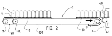
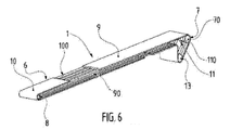
前記受け取り面6は、少なくとも部分的に長手方向に延在し、循環し、戻りの場合は、第1の端部の位置で、たとえば、少なくとも1つの第1の駆動ローラ7の形態を呈する駆動手段の周囲に、また、第2の端部の位置で少なくとも1つのリターンローラ8の周囲に巻き付けられる。したがって、前記第1のローラ7の回転作動によって、受け取り面6が連動され、製品2が移動する。この受け取り面6の移動方向を図1の矢印でモデル化した。この矢印の大きさと速度にはいかなる関係もない。 The receiving surface 6 extends at least partially longitudinally, circulates, and in the case of return, at the position of the first end, a drive, for example in the form of at least one first drive roller 7. It is wrapped around the means and around the at least one return roller 8 at the position of the second end. Therefore, by the rotation operation of the first roller 7, the receiving surface 6 is interlocked and the product 2 moves. The moving direction of the receiving surface 6 is modeled by the arrow in FIG. There is no relationship between the size and speed of this arrow.
有利には、コンベヤ装置1は、前記受け取り面が、独立した少なくとも1つの第1の区間9および第2の区間10を含み、それらの前進方向に互いに延長線上にあることを特徴とする。したがって、受け取り面6は、長手方向すなわちコンベヤ1が搬送する製品の駆動循環方向に、少なくとも2つの部分に分割される。換言すれば、区間9と10は、特にそれらの個々の駆動、したがって、それらの前進速度に関して別々に制御可能である。好ましくは、第1の区間9および第2の区間10の長手方向の寸法は、乗り換えられる製品群5の長手方向の寸法に本質的に対応し、乗り換えられる製品群の寸法は、一般に積載領域3の長手方向の寸法に対応する。
Advantageously, the
装置1は、受け取り面6を再分割する複数の付加的な区間を含むことができ、前記付加的な区間は、独立して設けられるか、あるいは、第1の区間9および第2の区間10のいずれか一方に合わせて制御される。
The
各区間9、10は、プラスチック化合物等の特に適切な材料からなる完成した長さのベルトまたはマットから構成可能である。区間は、特にその圧縮を局部的に可能にする弾性特性を有することができよう。そのため、区間9、10が突き合わされるとき、ベルトまたはマット間の接合は、窪みもなく間隔もあかない結合を保証する圧縮によって実施される。
Each
各区間9、10の長さは、好ましくは同じである。さらに、この長さは、積載領域3または上流ユニット4の製品2の乗り換え部分の寸法に対応し、すなわち、好ましくは乗り換え部分の寸法に等しい。これによって、下流区間9、10の最も上流の製品と、上流区間10、9の最も下流の製品の間に著しいスペースを設けることなく、前記領域3の位置に存在する製品2の1つのセグメント全体を、向かい合って位置する区間9、10に向かって確実に乗り換え可能であることを保証する。
The length of each
他方で、前記第2の区間10は、前記受け取り面6の長さの第2の部分に沿って延在する。この第2の部分は、前記第1の部分9とは異なるものであり、少なくとも第2の駆動ローラ11の周囲に巻き付けられる第2の巻き付け手段100を介して支持される。そのため、前記区間9、10は互いに前後に延在し、双方の間で可変の間隔を伴ってつながれ、この間隔は、前記区間の個々の位置に応じて制御される。
On the other hand, the
図2から図5に示した実施形態から分かるように、各区間9、10の駆動ローラ7、11は、好ましくは互いに間隔をあけた同一水平面に配置可能である。そのため、一方の区間9は、他方の区間10を上回る長さのループにわたって循環する。これは、その駆動ローラ7が他方の駆動ローラ11に対して偏心するように配置されるためである。したがって、より遠くにある駆動ローラ7によって、この区間9の移動速度が適合される。区間9、10は、相対的に特別な加速および減速等の速度において様々な駆動構成を有する。
As can be seen from the embodiment shown in FIGS. 2 to 5, the
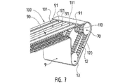
図6と図7に示した別の1つの実施形態によれば、区間9、10の駆動ローラ7、11を同軸に配置可能であり、その場合、それぞれが少なくとも1つの駆動ローラ70、110から構成される。各駆動ローラ7、11は、互いに同軸に取り付けられた複数の駆動ローラ70、110から構成可能である。
According to another embodiment shown in FIGS. 6 and 7, the
さらに、限定的ではないが、この特別な実施形態によれば、駆動ローラ7、11は、多数にすることが可能である。図6と図7から分かるように、第1の駆動ローラが下流端に配置される一方で、相補的な駆動ローラ13が下方に偏心される。この構成は、特に、コンベヤ装置1のベルト全体の張りをよりよくし、特に前記ベルトの全部または一部の加速または減速時の駆動を向上させる。
Furthermore, but not by way of limitation, according to this particular embodiment, the
さらに、この構成では、図6から分かるように、駆動手段が、1つまたは複数の駆動ローラ7、11の反対端に位置する単一のリターンローラ8を含むことができる。区間9、10は、その場合、この同じリターンローラ8の周囲に巻き付けられる。
Furthermore, in this configuration, as can be seen in FIG. 6, the drive means may comprise a single return roller 8 located at the opposite end of the one or
そのため、各区間9、10は、その固有の手段に応じて、互いに同じ速度または異なる速度とすることができる速度で駆動され、ローラ7、11の駆動速度を変える可能性を提供し、生産の特別なニーズと、本発明によるコンベヤ装置1が製品2を間で搬送する下流および上流のユニットのニーズとに各区間9、10の速度を適合させる。
Therefore, each
特に、コンベヤ装置1の長さは、一方では、積載領域3または上流ユニットと、下流ユニット4との間で可能な用地に応じて、他方では、前記下流ユニット4の公称補給速度と、積載領域3の位置での製品2の数に対して可能な積載速度とに応じて、さらには、向かい合った区間の一方および他方により覆われる距離に応じて、特に前記公称補給速度に応じて、適合される。より詳しくは、コンベヤ装置1の長さは、補給連続性を維持しながら、到達可能な速度と走行すべき距離に応じて、一方の区間(すなわち、積載された製品2の配置を保持してスイープを回避する区間)が、他方の区間に追いつくまで十分かつ安全な加速を得るように決定可能である。
In particular, the length of the
好ましくは、前記第2の区間10の前記第2の巻き付け手段100は、図2〜図5から分かるように前記リターンローラ7の周囲に、あるいは、それらの固有のリターンローラ(図示せず)の周囲に、さらには、前記リターンローラ7と異なるがアラインメントされている(換言すれば、前記コンベヤ装置1の幅に応じて同軸に設けられている)リターンローラの周囲に、巻き付けにより取り付け可能である。さらに、各リターンローラ7は、回転自在に設けることができ、個々の区間9、10の周囲への巻き付け手段90、100の張りと、個々の区間の自由な移動とを保証する。図示されている実施形態によれば、リターンローラ7は、下流ユニット4の反対側のコンベヤ1の端部に位置する。
Preferably, the second wrapping means 100 of the
区間9、10は、駆動ローラ7、11とリターンローラ8との間に位置する固有の中間ローラ(図示せず)を共有し、あるいは備えることができることに留意されたい。これらの中間ローラは、区間9、10の通過時にそれらを支持可能であり、個々の巻き付け手段90、100は、それらの張りを維持する。
It should be noted that the
より詳しくは、好ましい1つの実施形態によれば、前記第1の巻き付け手段90および第2の巻き付け手段100は、前記第1の駆動ローラ7および前記第2の駆動ローラ11と相互に係合する少なくとも1つのベルトの形態を呈することができる。その場合、駆動は、駆動ローラ7、11を中心とする摩擦によって、あるいは、対応する歯列がベルトに設けられている場合は、かみ合わせによって行われる。
More specifically, according to a preferred embodiment, the first winding
図7に示した特定の実施形態によれば、駆動ローラ7、11の周囲でのかみ合わせにより駆動を操作可能である。そのため、各ベルト91、101には、対応する歯列12が設けられている。さらに好ましくは、先に述べたように、前記第1の駆動ローラ7および第2の駆動ローラ11は、互いに少なくとも1つの第1の駆動ホイール70と少なくとも1つの第2の駆動ホイール110とを有することができ、その場合、これらのホイールは、ベルト91、101の歯列12に対応する係合歯列120を有してかみ合わせを保証する。
According to the particular embodiment shown in FIG. 7, the drive can be operated by meshing around the
好ましくは、各区間9、10に接続されたベルト91、101は、全部で少なくとも2個、特に3個さらには4個であって、平行に間隔をあけられており、コンベヤ装置1の長さに沿って延びるほぼ垂直な面に沿って延在し、そこに連結される各区間9、10の側面安定性を保証する。そのため、第1の区間9のベルトを装置1に沿って両側に配置可能である一方で、第2の区間10のベルトを内側に配置するか、あるいはその逆に実施し、さらには、区間9、10の個々のベルトを互いの間に、または1対2もしくは1対3等に配置可能である(すなわち、1つの区間9または10の各ベルト91または101は、他の区間10または9の少なくとも1つの別のベルト101または91を互いに横に含む)。
Preferably, the total number of
さらに、各ベルト91、101は、その区間9、10の内部に結合するように構成される。換言すれば、各区間9、10は、製品2の受け取り面と反対面の位置でその1つまたは複数のベルト91、101で固定される。すなわち、各マットは、その1つまたは複数のベルト91、101に下部で固定される。
Further, each
別の実施形態によれば、第1の巻き付け手段90および第2の巻き付け手段100は、少なくとも1つ、好ましくは複数のチェーンまたはラックの形状を呈することができる。そのため、個々の駆動ローラ7、11は、それらの係合駆動を保証するように相補的に設けられる。
According to another embodiment, the first wrapping means 90 and the second wrapping means 100 can take the form of at least one, preferably a plurality of chains or racks. Therefore, the
したがって、個々の独立した複数の区間9、10によるコンベヤ装置1の構成によって、積載領域3または上流ユニットから下流ユニット4へと、その長さにわたって異なる様々な速度で製品を搬送することができる。
Therefore, the configuration of the
さらに、2つの速度を有する二重区間を備えた、こうした単一コンベヤ1によって、異なる複数のコンベヤを突き合わせたものに対してフロア用地を最適化することができ、積載領域3または上流ユニットと下流に配置されるユニットとの間で生産ラインが短縮される。特に、明確な1例では、本発明は、梱包する準備のできた製品を上流で供給するユニットと、複数のベルトで直接供給される下流のバンドリング機械との間で、このようなコンベヤ装置1の設置をよりコンパクトにすることができる。
Furthermore, such a
好ましくは、区間9、10に乗り換えられる製品群5の長手方向の寸法は、前記区間の長手方向の寸法に非常に近い。特に、乗り換えられる製品群5と、乗り換え時の区間の位置とは、乗り換えられる製品群5の最も下流の淵と、これを受け取る区間の最も下流の縁とを隔てる距離が短くなるように、好ましくは1つのボトルのサイズ未満になるようにされる。乗り換えられる製品群の最も上流の縁と、これを受け取る区間の最も上流の縁とを隔てる距離についても同様である。
Preferably, the longitudinal dimension of the product group 5 that is transferred to the
区間は、所定の位置に戻るように、下流端で湾曲する行程に沿って循環する。この曲率は、その後で製品が循環するコンベヤの上流端と共に凹部を形成し、上流端もまた湾曲している。このように形成された凹部を埋めるようにデッドプレートを設け、上流の製品を移動させる区間の作用下での上流の製品のスラストを計算に入れ、次のコンベヤに到達するまでデッドプレート上で上流の製品を押すようにする。 The section circulates along a path that curves at the downstream end so as to return to a predetermined position. This curvature forms a recess with the upstream end of the conveyor through which the product then circulates, and the upstream end is also curved. A dead plate is provided to fill the recess formed in this way, and the thrust of the upstream product under the action of the section that moves the upstream product is taken into account, and the upstream of the dead plate on the dead plate until reaching the next conveyor. To press the product of.
好ましくは、レーンを画定する壁がデッドプレート上に延在する。レーンを画定する壁に関しては、区間の行程の一部に面して延在させることができる。特に、多数の壁を有するトランスファー工具は、この工具が区間上に製品を配置するとき、工具の壁が、下流で機械のレーンを画定する壁に向かい合う位置で、その動きを終了すると考えることができる。その場合、製品は、連続する壁により画定されるレーン内に絶えず送られ、これによって5点形が形成されるあらゆるリスクが回避される。 Preferably, the walls defining the lanes extend over the dead plate. With respect to the wall defining the lane, it may extend over part of the travel of the section. In particular, a transfer tool with multiple walls may be considered to end its movement when the tool places a product on a section, with the wall of the tool facing the wall defining the lane of the machine downstream. it can. In that case, the product is constantly fed into the lane defined by the continuous walls, which avoids any risk of forming a pentagon.
本発明はまた、前記製品2が秩序立てた構成で送られる製品2の搬送方法に関する。 The invention also relates to a method of transporting a product 2 in which the product 2 is delivered in an ordered configuration.
このような方法は、積載領域3または上流ユニットから受け取り面6を介して下流に配置されたユニット4へと前記製品2を搬送することからなる。
Such a method consists of transporting the product 2 from the
特に、積載領域3を有する実施形態では、適切な乗り換え手段を介して、特に、1つの面から他の面への横方向水平面のスライドによって、積載領域3からコンベヤ1の受け取り面6に製品群ごとに製品2が乗り換えられる。
In particular, in embodiments having a
有利には、上記の方法は、独立して駆動されて互いに移動する第1の区間9および第2の区間10からなる受け取り面6を使用することを特徴とする。
Advantageously, the method described above is characterized by the use of a receiving surface 6 consisting of a
そのため、前記積載領域3または上流ユニットの位置で前記第1の区間9を停止し、製品群ごとに前記積載領域3または上流ユニットから前記製品2の乗り換えを行う一方で、前記第2の区間10は所定の速度で駆動されて、前記下流ユニット4の位置で製品を排出することを保証する。このような工程の1例を図2に示した。
Therefore, the
したがって、区間9、10が積載領域3に向かい合って停止あるいはほぼ停止すると、この区間9、10から構成される受け取り面6へ製品を乗り換えるときに製品位置が変更されるリスクが最小化される。
Therefore, if the
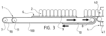
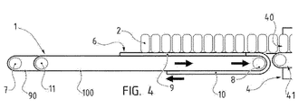
その後、前記第2の区間10の前記所定の速度を上回る速度まで前記第1の区間9を加速し、この加速は、できるだけ連続した搬送面を形成するように、前記第1の区間9の下流端が前記第2の区間10の上流端に当接するかまたは最も近くなるまで行われる。この2つの工程の1例を図3と図4に示した。
Then, the
加速は、区間9、10の停止位置から中間位置を経て第2の区間の直後で所望の駆動速度に到達するまで、通過中の位置変更リスクを制限するために、コンベヤ1の長さ、特に、第2の区間に追いつくために第1の区間が走行すべき距離に応じて、また一方では、運ばれる製品2のタイプに対して計算されることに留意されたい。
Acceleration is carried out in order to limit the risk of repositioning during passage, in particular the length of the
そのため、前記区間10の速度あるいはそれよりもやや速い速度に到達するまで第1の区間9の速度を減速し、それによって、前記区間9、10の各々を構成するベルトまたはマット間の接合を完全に保証する。特に、減速は、区間9、10のマットの対応する端部の接触が、場合によっては、前記製品2の配置の保持に有害であり、衝突なしに実施されることを保証する。この減速は、区間9、10の個々の端部が接触する前後の突合せの瞬間に実施可能である。
Therefore, the speed of the
したがって、下流ユニットは、好ましくは互いに並んだ複数の縦列により、長手方向に続く製品を供給される。この連続供給は、2つの区間が相互の間にスペースなしに、前後にあることにより得られる。そのため、下流ユニットは、交互に第1の区間の製品、次いで第2の区間の製品を供給され、以下同様に行われる。一方の区間が下流の機械を供給すると、他方の区間は製品を受け取り、次いで、一方の区間に追いつくために加速されて、下流の機械に製品を連続供給するようにする。このようにして、下流の設置場所における多数のレーンへの低速供給を利用し、こうした低速で下流ユニットに供給する1つの区間と、上流ユニットから製品群として乗り換えられる製品を受け取るために停止している別の区間との間に形成される隙間を、一段と速い速度によって解消するまで、追いつくようにされる。 Therefore, the downstream unit is supplied with the products that run longitudinally, preferably by a plurality of columns that are aligned with one another. This continuous feed is obtained by the two sections being one behind the other, with no space between each other. Therefore, the downstream unit is alternately supplied with the product of the first section, then the product of the second section, and so on. As one leg feeds the downstream machine, the other leg receives the product and is then accelerated to catch up with the one leg, continuously feeding the downstream machine. In this way, the low speed supply to a large number of lanes in the downstream installation is used, and one section is supplied to the downstream unit at such a low speed and stopped to receive the products to be transferred as a product group from the upstream unit. The gap formed between the other section and the other section is caught up until it is eliminated by the higher speed.
先に述べたように加速および減速は、対応する区間9、10により運ばれる製品2の位置変更または落下リスクを最大限制限するために計算される。
As mentioned above, accelerations and decelerations are calculated in order to maximally limit the risk of repositioning or falling of the product 2 carried by the
換言すれば、図4から分かるように、2個の区間9、10は、後の区間が前の区間に追いつくと、ほぼ同じ前進速度を有する。
In other words, as can be seen in FIG. 4, the two
このようにして、製品2の排出中である第2の区間に追いつき、このように運ばれる前記製品2の補給フローを連続させることを保証する。 In this way, it is ensured that the product 2 is catching up in the second interval during discharge and that the supply flow of the product 2 carried in this way is continuous.
特に、接合後は製品2をやや詰めることができ、第1の区間9により導かれる先頭の製品2と、下流で第2の区間10により支持される最後尾の製品2との間のずれを最小化する。こうした詰め込みは、下流ユニット位置での下流の搬送よりも受け取り面6の位置での上流の搬送を多少速くすることを保証することによって得られる。
In particular, after joining, the product 2 can be slightly packed, and there is a gap between the leading product 2 guided by the
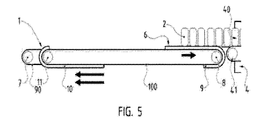
付加的に、前記第2の区間10により前記下流ユニット4の位置で製品2を排出した後、少なくとも前記積載領域3または上流ユニットまでの復路に沿って第2の区間10を駆動する。この時、第2の区間10は製品2がなく空であり、下方に位置するので、したがって、積載領域3または上流ユニットに向かい合った場所にできるだけ早く合流するために高速駆動することができる。このような工程の1例を図5に示した。
Additionally, after the product 2 is discharged at the position of the downstream unit 4 by the
次いで、前記第2の区間10を停止する。この工程は、再び図2の様相を呈する。
Then, the
要約すると、区間9、10は可変の間隔を伴って連続しており、この間隔は、一方では、他の区間が積載領域3または上流ユニットの位置での積載を停止した状態にあるとき、製品2を積載された下流の区間が下流ユニット4に供給するために移動すると増加または開き、他方では、上流の区間がより速い速度で移動して、公称速度に減速された他方の区間に合流する一方で下流の区間が前記下流ユニット4を補給すると減少する。さらには、他方の区間が前記下流ユニット4を補給しながら製品2を排出するとき、積載領域3までの空の区間の下方の復路では間隔が開く。
In summary, the
図2から図5では、正確な値または比率なしにもっぱら参考として、各区間9の他方の区間10に対する移動速度を概略的に矢印で示した。
In FIGS. 2 to 5, the moving speed of each
さらに、上記の速度は可変であり、ラインの生産および/または梱包に固有のデータに応じて、たとえば網羅的ではないが、運ばれる製品2に応じて、また装置1や積載領域3の長さ、あるいは下流ユニット4で必要な補給速度に応じて正確に決定される。
Furthermore, the speeds mentioned above are variable, depending on the data specific to the production and / or packaging of the line, for example, but not exhaustively, depending on the product 2 to be carried and the length of the
以下同様であり、上記の工程が繰り返されて下流ユニット4の連続補給を保証し、その一方で積載面3は、不連続に製品群を供給する。
The same applies hereafter, and the above steps are repeated to ensure continuous replenishment of the downstream unit 4, while the
さらに、各区間9、10の速度は、下流ユニットの公称補給速度に依存するが、また、この下流ユニットと積載領域3または上流ユニットとの間の長さにも依存する。これらの区間9、10の進行速度はまた、特に、バンドリング機械タイプの下流ユニットに装備されるコンベヤに対して、生産サイクルに応じた製品補給を調整するために修正可能である。
Furthermore, the speed of each
本発明は、コンベヤ装置1とその搬送方法とを介して、生産および/または梱包のラインの2か所の間で製品2を進ませながら非5点形の当初の構成を維持し、位置変更のリスクを抑えることができる。さらに、製品がまだない場合は、製品を秩序立てるためにより長い期間を付与し、積載領域3の位置で製品を蓄積することを操作可能である。いずれにしても、この積載領域3は、公知の別の蓄積領域よりも用地が狭くて済む。付帯的に、製品2を導いてこれを秩序立てるために、この積載領域3のあらゆるタイプの補給を検討可能である。
The present invention maintains a non-five-point initial configuration while advancing a product 2 between two points of a production and / or packing line through a
本発明は、単一または複数のレーン42を有する下流ユニット4に製品補給するための、あらゆるタイプの製品2の搬送に適用される。
The invention applies to the transport of any type of product 2 for replenishing a downstream unit 4 having single or
したがって、
−必要に応じて横軸に沿って連続移動可能な、矩形面タイプの積載領域、
−長手方向すなわち、横軸に対して垂直かつ水平な第1の縁で、上記の矩形面に沿って進む受け取り面、
−反対側の長手方向の縁に沿って循環する、搬送による供給手段、
−受け取り面により供給され、したがってその延長線上にあるバンドリング機械タイプの下流ユニット、
を含む完全な装備を必要に応じて得る。
Therefore,
-A rectangular surface type loading area, which can be moved continuously along the horizontal axis if necessary,
A receiving surface which runs along said rectangular surface at a first edge which is longitudinal, ie perpendicular and horizontal to the transverse axis,
Feeding means by transport, circulating along the opposite longitudinal edge,
A downstream unit of the bundling machine type supplied by the receiving surface and thus on its extension
Get full equipment including as needed.
製品は、この装備全体において非5点形で循環し、その個別のレーンで直接バンドリング機械に運ばれる。 The product circulates in a non-five-point fashion throughout this equipment and is carried directly to the bundling machine in its separate lane.
以上から分かるように、コンベヤ装置1は、製品2を支持するための受け取り面6を含む。受け取り面6は、好ましくは準平面であり、さらには平面であって、添付図に示すように、好ましくは、準水平面、さらには水平面に延在する。換言すれば、製品2は、コンベヤ装置1でのそれらの搬送中、準平面でほぼ水平な面6により支持される。そのため、受け取り面6は、処理すべき製品2の体裁およびこの受け取り面6におけるそれらの配置がどのようなものであろうと、複数の製品2を収容可能である。実際、受け取り面6は、垂直壁または、バケットとも呼ばれるタンクのような保持要素の存在を必要としない。
As can be seen, the
このタイプの要素は、装置1への特に製品2の配置を課すことに加えて、少なくとも製品2の寸法、さらにはバケットの場合は製品の形状に特有の不都合を有する。
In addition to imposing, in particular, the placement of the product 2 on the
これらの保持要素の別の不都合は、保持要素がそれらのレイアウトによって、ライン内部の製品の進路を続行するために、特に下流ユニットに向けて進むために、製品がその支持面を離れる仕方にある。実際、例として、横方向の垂直壁の存在は、製品2が正面から出ることを一切阻止し、その一方で、長手方向のバケットの存在は、製品がこのように出ることを可能にするが、しかし、製品2が縦列の場合に限られる。このような要素はまた、装置の内部で著しく場所をとる。 Another disadvantage of these holding elements is how, due to their layout, the holding elements leave their support surface in order to continue the course of the product inside the line, in particular towards the downstream unit. . In fact, by way of example, the presence of a lateral vertical wall prevents the product 2 from leaving the front at all, while the presence of a longitudinal bucket allows the product to leave in this way. However, this is limited to the case where the product 2 is a column. Such elements also take up significant space inside the device.
そのため、受け取り面6は、好ましくは、搬送中に製品2を保持するためのバケットまたは垂直壁タイプの要素がない。したがって、受け取り面は、有利には、形や寸法とは無関係に製品2を受け取ることが可能であり、これらの製品2は秩序立てられており、あるいはそうでない。例として、受け取り面は、高さが垂直または非垂直で底辺が正方形または三角形の製品2を支持可能であり、これらの製品2は、受け取り面6で秩序立てられずに任意に配置可することができる。 As such, the receiving surface 6 is preferably free of bucket or vertical wall type elements for holding the product 2 during transport. Thus, the receiving surface is advantageously capable of receiving products 2 regardless of shape or size, these products 2 being ordered or not. By way of example, the receiving surface can support products 2 with a vertical or non-vertical height and a square or triangular base, which products 2 can be arranged arbitrarily without being ordered on the receiving surface 6. You can
したがって、このような実施形態では、受け取り面6は単独で、もっぱら粘着により製品2の位置決めと前進を保証する。 Thus, in such an embodiment, the receiving surface 6 alone ensures the positioning and advancement of the product 2 solely by adhesion.
さらに、このような実施形態では、コンベヤ1は、受け取り面6における製品2の配置がどのようなものであろうと、基本的に同じくコンベヤの形態を呈する搬送装置41で、受け取り面が支持する製品2を正面から送ることができる。このため、その後の生産および/または梱包ラインに向かって製品2の移動を保証する搬送装置41で製品2の乗り換えを実施するためのアクチュエータは一切不要である。製品2は、単に、コンベヤ1の動作によって搬送装置41に向けて導かれる。その場合、搬送装置41は、コンベヤ1の延長線上にあり、その受け取り面は、受け取り面6と同高である。図2から図5に示したように、コンベヤ1と搬送装置41との間にデッドプレートを設けてもよい。換言すれば、製品2は、長手方向の搬送によりコンベヤ1から搬送装置41に移行する。
Furthermore, in such an embodiment, the
搬送装置41は、製品2のフローをややコンパクトにするように、製品2の排出時に区間9、10よりもやや低速で循環可能であることに留意されたい。実際、特に安全上の理由から、区間9、10の下流および/または上流端は製品2を支持しない。なぜなら、一般には、たとえば前記受け取り面6で全体が保持されないことによってこの製品2の落下を発生するリスクよりもむしろ、受け取り面6に製品2を少なく配置することが好ましいからである。
It should be noted that the carrier device 41 can circulate at a slightly slower speed than the
したがって、コンベヤ装置1は、それらの体裁および受け取り面6における配置とは無関係に製品2を連続搬送するだけではなく、これらの製品2を単純に後続ラインに導くことができる。
Therefore, the
より詳しくは、受け取り面6の独立した各区間9、10は、好ましくは準水平さらには水平面に延在する準平面さらには平面の連続面により図示されている。
More specifically, each
この連続面は、その面積全体で製品2を支持可能な面である。そのため、プレートは連続する上面を含むが、しかし、製品2の支持を損なわないために穴が十分に小さい場合は穿孔プレートもまた、このような面を含むことができる。 This continuous surface is a surface capable of supporting the product 2 over its entire area. As such, the plate includes a continuous top surface, but the perforated plate can also include such a surface if the holes are small enough so as not to impair the support of the product 2.
受け取り面6に関しては、搬送方法中の工程に応じて交互に連続および不連続とすることができる。そのため、第1の区間9の積載時に区間10は排出中であり、したがって、2つの区間は互いに間隔をあけられている。第2の区間10の積載時も同様である。それに対して、第1の区間9が積載されると、この区間は第2の区間10に合流するために加速され、その場合には一緒に連続受け取り面6を形成し、すなわち、第1の区間9および第2の区間10は同高になり、これらの2つの区間の間に隙間がない。第2の区間10が積載されてその下流縁により第1の区間9の上流縁に合流した場合も同様である。
The receiving surface 6 can be alternately continuous and discontinuous, depending on the steps in the transport method. Therefore, the
好ましくは、特に積載領域3から区間9、10の一方に製品2を乗り換える場合、区間9、10のいずれか一方に配置すべき製品2の全体が、この区間9、10の停止時に乗り換えられる。そのため、積載される区間9、10が停止され、上に配置される製品2の全体が特に横方向のスラストにより乗り換えられ、その後、積載された区間9、10は再び循環される。その場合、積載工程は、区間9、10の各停止期間の際に製品2の段階的な乗り換えを伴う一連の複数の進行−停止段階を一切必要としない。その結果、速度が改善される。
Preferably, particularly when transferring the product 2 from the
本発明の好ましい実施形態によれば、その場合、受け取り面6は準平面であり、準水平面に延在し、少なくとも1つの第1の連続区間9および第2の連続区間10を含み、これらの製品2の配置に関係なく各区間が複数の製品2を支持することができる。
According to a preferred embodiment of the invention, the receiving surface 6 is then quasi-planar, extends in the quasi-horizontal plane and comprises at least one first
したがって、コンベヤ装置1は、準平面で準水平なその受け取り面6によって、自由に配置可能な、すなわち、バラ積みであっても、たとえば縦列、すなわちコンベヤ装置1の搬送方向に沿って延在する1つまたは複数の列であっても、製品2の集合を移動可能である。好ましくは、製品2は、互いに平行な、すなわち非5点形の行列の複数の縦列で配置される。
Thus, the
さらに、コンベヤ装置1は、準平面で準水平なその受け取り面6によって、特に積載領域3を起点としてスラスト運動により製品2を受け取ることができる。
Furthermore, the
以上から分かるように、また図1および図8から図10に示したように、本発明は、その別の側面によれば、少なくとも以下を含む設備、すなわち、
−上記のような積載領域3、および
−上記のようなコンベヤ装置1
に関する。
As can be seen from the above, and as shown in FIGS. 1 and 8 to 10, the invention provides, according to another of its aspects, an installation comprising at least the following:
-The
Regarding
有利には、積載領域3は、蓄積面、すなわち、前記製品2の生産および/または梱包のラインの2つの連続する機械の間を通過する製品2を受け取る緩衝面の役割を果たす。このような蓄積面は、特に2個の機械の間を循環する製品2のフローを管理すると共に、ラインの速度を最適化するように、これらの機械の個々の速度と一時的な停止とに応じて当該フローを適合させることが可能である。
Advantageously, the
積載領域3は、コンベヤ装置1の長手方向の縁の一方に基本的に隣接し、受け取り面6と同高にあるので、製品2は、積載領域3から受け取り面6まで、単に横方向の準水平な側面スラストによって乗り換え可能である。このような乗り換えにより、有利には、製品2の長手方向の整列を保持できる。
The
好ましくは、積載領域3は準平面、さらには平面であり、好ましくは、準水平さらには水平面に延在する。積載領域は、基本的に、上流縁から下流縁に向かって延在し、下流縁は、受け取り面6と突き合わせられる。この積載面3により支持される製品2は、下流縁に向かって移動し、すなわち特に横方向、さらには、コンベヤ装置1が延在する方向に対してほぼ垂直に移動する。
Preferably, the
考えられる付加的な1つの特徴によれば、設備はさらに、積載領域3から受け取り面6まで製品2を乗り換えるための乗り換え手段を含む。
According to one possible additional characteristic, the installation further comprises transfer means for transferring the product 2 from the
このような乗り換え手段は、特に、横方向の準水平なスイープによって製品2の1つまたは複数の長手方向セグメントを押すためのスラスト手段の形態を呈することができる。特に、製品2の複数の長手方向セグメントを同時に乗り換えるためのスラスト手段は、スイープ中にこれらのセグメントを分離して保持し、複数のセグメントとしての、すなわち非5点形のそれらの配置を保持することができる。そのため、前述のように、また図8から図10に示したように、1つまたは複数のスラストプレート14を含むことができ、スラストプレート14の数は、乗り換えるべき製品群5を含む長手方向セグメントの数と相関関係にある。例として、スラスト手段は、乗り換えるべき製品群5を構成する長手方向ラインと同数のプレート14を含むことができる。あるいは好ましくは、スラスト手段は、n個の長手方向セグメントからなる製品群5を乗り換える場合、乗り換え時に各セグメントが2個のプレート14の間にくるように少なくともn+1個のプレート14を含む。プレート14の間の間隔は、追加工具を発生せずに各種の体裁の製品を容易に取り扱えるように調整可能である。乗り換え時には必ずしも全てのプレート14が使用されるわけではないことに留意されたい。そのため、例として、コンベヤ1の位置では3つの縦列でも5つの縦列でも製品2を送るのに同一の乗り換え手段を使用可能であり、コンベヤ1の位置での様々な構成に対して調整せずに同じ乗り換え手段を使用できる。簡単に言えば、この場合には3つの縦列の同時乗り換え時に2個のスラストプレート14が使用されることはない。
Such transfer means may in particular take the form of thrust means for pushing one or more longitudinal segments of the product 2 by means of a lateral quasi-horizontal sweep. In particular, the thrust means for simultaneously changing over a plurality of longitudinal segments of the product 2 keep these segments separate during the sweep and keep their arrangement as a plurality of segments, i.e. non pentagonal. be able to. As such, it may include one or
考えられる付加的な1つの特徴によれば、設備はさらに、積載領域を供給するためのコンベヤ供給手段を含む。このような供給手段は、特に、たとえばラベラーまたはコルク打栓機タイプの上流ユニットの出口から積載領域3の上流位置の上流縁まで延在する。この供給手段では、製品2は、基本的に1つまたは複数の列、好ましくは単一列に沿って送られる。
According to one additional possible feature, the installation further comprises conveyor feeding means for feeding the loading area. Such a supply means extends in particular from the outlet of an upstream unit, for example of the labeler or cork stopper type, to the upstream edge of the upstream position of the
好ましくは、少なくとも1つの部分、特に、このような供給手段の下流部分は長手方向に延在し、積載面3の上流縁に沿っている。製品2を支持する供給手段の上面は基本的に準平面、さらには平面であり、好ましくは準水平さらには水平面に延在する。供給面に沿った供給手段の部分の上面は、好ましくは供給面と同高で供給面に突き合わされ、すなわち2つの面の間に隙間はない。
Preferably, at least one part, in particular the downstream part of such a supply means, extends longitudinally and along the upstream edge of the
したがって、積載領域3から受け取り面6上まで製品2を乗り換えるための前述と同じタイプの乗り換え手段を用いて、供給コンベヤから積載領域3に向かって製品2を乗り換えることができる。積載領域3から受け取り面6上まで製品2を乗り換えるために使用される乗り換え手段は、たとえば、積載領域3への製品の乗り換えにも同様に使用可能である。
Therefore, the product 2 can be transferred from the supply conveyor to the
有利には、積載領域3から受け取り面6上まで製品2を乗り換えるための乗り換え手段は、同様に上記のスラスト手段であり、製品2の長手方向の整列を保持するようにされる。
Advantageously, the transfer means for transferring the products 2 from the
考えられる付加的な1つの特徴によれば、設備はさらに下流ユニット4を含む。 According to one possible additional characteristic, the installation further comprises a downstream unit 4.
有利には、設備は、たとえばコルク打栓機またはラベラータイプの上流ユニットから、たとえばバンドリング機械または包装機タイプの下流ユニット4に向かって製品2を搬送可能であり、1つまたは複数の平行線に沿って製品2を配置するために積載領域3または蓄積面をうまく利用すると共に、複数の連続レーンに沿った供給、すなわち下流ユニット4の連続製品間の追加スペースを生じることのない供給を可能にするためにコンベヤ装置1をうまく利用する。
Advantageously, the installation is capable of transporting the product 2 from an upstream unit, for example of a cork stopper or labeler type, towards a downstream unit 4, for example of a bundling machine or packaging machine, one or more parallel lines. Makes good use of the
したがって、幾つかの実施形態では、設備は、単線フローの製品2を、複数の平行な列に配置された多線フローに変換することができ、列の数は、下流ユニット4での形成を望むロットの構成と、乗り換え手段のキャパシティとに応じて決定される。 Thus, in some embodiments, the facility can convert a single wire flow product 2 into a multi-wire flow arranged in a plurality of parallel rows, the number of rows forming the downstream unit 4. It is determined according to the desired lot structure and the capacity of the transfer means.
このような設備の入口および出口の製品2のフローは、積載領域3に出入りするための製品2の乗り換えが逐次的に実施されるにもかかわらず連続していることに留意されたい。これらの乗り換えによって、単線フローを多線フローに同時に変換できるばかりでなくまた製品2を蓄積することができる。
It should be noted that the flow of product 2 at the entrance and exit of such a facility is continuous despite successive transfers of product 2 to and from
そのため、このような設備は、特に、積載領域3およびコンベヤ1が、上流ユニット3と下流ユニット4との間で、分別装置(単線フローから、より広幅のバラ積みフローに移行可能にする)、製品のバラ積みの蓄積面、次いで、製品をレーンに分ける装置の連続に有利には代わることにおいて、従来の設備から区別される。
Therefore, such a facility is particularly suitable for the
実際、分別装置−バラ積み蓄積−レーン分けという公知の連続が占有するフロア面積は大きく(全てが一連の連続コンベヤを必要とするため)、レーン分け位置で製品のブロックを発生し、幅広い範囲の寸法の製品と相容れない。 In fact, the floor space occupied by the known segregator-bulk storage-lane segregation occupies a large floor area (since they all require a series of continuous conveyors), generating product blocks at the lane segregation location, which results in a wide range of coverage. Incompatible with dimensional products.
それに対して、提案されている設備は小型、経済的、多様な体裁用であり、製品2の流動的な通行を可能にする。 On the other hand, the proposed equipment is compact, economical, and versatile in appearance, allowing the product 2 to flow in a fluid manner.
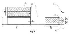
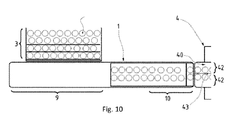
図8から図10に示したように、製品2は、横方向に並んだ長手方向セグメントの形態で配置可能であり、受け取り面6上にそのまま乗り換えることができる。 As shown in FIGS. 8 to 10, the products 2 can be arranged in the form of laterally aligned longitudinal segments, which can be transferred directly onto the receiving surface 6.
このため、使用される乗り換え手段は、準水平な横方向スイープ運動に従って、その場合に停止している受け取り面6の第1の区間9に所望の数の製品2の列を乗り換えるために1つまたは複数のスラストプレート14を含む。例として、図8から図10に示された乗り換え手段は、3個の長手方向プレート14を含んで、製品2の2個のセグメントを同時に乗り換える。一般に、乗り換えられる製品群5は、下流ユニット4に形成されるロットと同数の列を含む。
For this reason, the transfer means used are one in order to transfer the desired number of rows of products 2 to the
そのため、図8に示した設備では、乗り換え手段が受け取り面6の第1の区間9に製品2の製品群5を乗り換えるために配置されるのに対し、第2の区間10は、コンベヤ装置1の下流の延長線上に配置される下流ユニット4の位置で製品2の製品群5を排出中である。
Therefore, in the equipment shown in FIG. 8, the transfer means is arranged to transfer the product group 5 of the product 2 to the
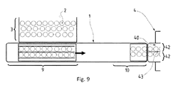
図9は、いったん第1の区間9に乗り換えられた製品群5の状況を概略的に示している。乗り換え手段は、まだ製品群5の位置にあり、格納される準備ができている。第1の区間9は、依然として停止しており、第2の区間10は、下流ユニット4の位置で製品2の排出を続けている。積載領域3に残っている製品2が積載領域の下流縁に向かって横方向に進んでいることが同様に確認される。この前進は、特に、横方向に循環する搬送手段の上面を積載領域が構成することによって操作可能にされている。
FIG. 9 schematically shows the situation of the product group 5 which has been changed to the
その場合、乗り換え手段が格納され、受け取り面6、より詳しくは受け取り面6の第2の区間10に製品2の新しい製品群5を乗り換えるように配置される。
In that case, the transfer means are stored and arranged to transfer a new product group 5 of products 2 to the receiving surface 6, more specifically to the
したがって、図10は、乗り換え手段が、第2の区間10に向けて製品群5を乗り換えるために位置決めされている最中の状況を示している。
Therefore, FIG. 10 shows a situation where the transfer means is being positioned for transferring the product group 5 towards the
この図では、第2の区間10がまだ積載面3の位置になく、したがって、まだ乗り換えを行うことはできない。第2の区間10は、下流ユニット4の位置で製品2の排出を終了する。いったん排出が終了すると、第2の区間を加速し、乗り換えのために積載領域3の位置に配置することができる。第1の区間9は、第2の区間10に合流し、その場合、受け取り面6が連続面を形成する。もちろん、方法のこの段階で区間9と10が突き合わされずに僅かな間隔をあけられる設備も同様に適しており、たとえばパレタイザーのように、下流ユニットが連続ではなく逐次的に動作する場合はなおさらである。
In this figure, the
当然のことながら、本発明は、上記の実施形態に制限されず、上記の特徴またはその幾つかの部分を結合することが可能であることが分かる。 Of course, it will be appreciated that the invention is not limited to the embodiments described above, but that it is possible to combine the features mentioned above or some parts thereof.
Claims (10)
−前記受け取り面(6)が、独立した少なくとも1つの第1の区間(9)および第2の区間(10)を含み、
−前記第1の区間(9)が、第1のモーター手段を介して駆動される、前記受け取り面(6)の長さの第1の部分に沿って延在し、
−前記第2の区間(10)が、第2のモーター手段を介して駆動される、前記第1の部分とは異なる前記受け取り面(6)の長さの第2の部分に沿って延在する、
ことを特徴とする、コンベヤ装置(1)。 A receiving surface (6) for the product (2) extending at least partially longitudinally along the closed loop stroke,
-The receiving surface (6) comprises at least one independent first section (9) and second section (10),
Said first section (9) extends along a first portion of the length of said receiving surface (6) driven via a first motor means,
The second section (10) extends along a second part of the length of the receiving surface (6) different from the first part, which is driven via a second motor means. To do
A conveyor device (1), characterized in that
−積載領域(3)または上流に位置するユニットから下流に位置するユニット(4)に向かって受け取り面(6)を介して前記製品(2)を搬送することからなり、
−受け取り面(6)が、独立して駆動される第1の区間(9)および第2の区間(10)を含み、
−前記積載領域(3)または上流ユニットの位置で前記第1の区間(9)を停止して前記積載領域(3)または前記上流ユニットから前記製品(2)を乗り換える一方で、前記第2の区間(10)が所定の速度で駆動されて前記下流ユニット(4)の位置で製品(2)を排出することを保証し、
−前記第2の区間(10)の前記所定の速度を上回る速度まで前記第1の区間(9)を加速し、この加速を、前記第1の区間(9)の下流端が前記第2の区間(10)の上流端に到達するまで実施する
ことを特徴とする、搬送方法。 A method of transporting a product (2), wherein the product (2) is arranged according to an ordered position,
-Conveying said product (2) via a receiving surface (6) from a loading area (3) or a unit located upstream to a unit (4) located downstream,
The receiving surface (6) comprises a first section (9) and a second section (10) which are independently driven,
-While stopping the first section (9) at the position of the loading area (3) or the upstream unit and transferring the product (2) from the loading area (3) or the upstream unit, while moving the second Ensuring that the section (10) is driven at a predetermined speed to discharge the product (2) at the position of the downstream unit (4),
-Accelerating the first section (9) to a speed above the predetermined speed of the second section (10), this acceleration being performed by the downstream end of the first section (9) A carrying method, characterized by carrying out until the upstream end of the section (10) is reached.
Applications Claiming Priority (5)
| Application Number | Priority Date | Filing Date | Title |
|---|---|---|---|
| FR1753137 | 2017-04-11 | ||
| FR1753137A FR3064989A1 (en) | 2017-04-11 | 2017-04-11 | CONVEYOR DEVICE AND METHOD FOR CONVEYING PRODUCTS |
| FR1755064A FR3064990B1 (en) | 2017-04-11 | 2017-06-07 | MULTI-LINE TRANSFER OF PRODUCTS |
| FR1755064 | 2017-06-07 | ||
| PCT/FR2018/050912 WO2018189485A1 (en) | 2017-04-11 | 2018-04-11 | Multiline transfer of products |
Publications (2)
| Publication Number | Publication Date |
|---|---|
| JP2020512965A true JP2020512965A (en) | 2020-04-30 |
| JP2020512965A5 JP2020512965A5 (en) | 2021-05-20 |
Family
ID=60202083
Family Applications (1)
| Application Number | Title | Priority Date | Filing Date |
|---|---|---|---|
| JP2020505538A Pending JP2020512965A (en) | 2017-04-11 | 2018-04-11 | Product multi-line transfer |
Country Status (7)
| Country | Link |
|---|---|
| US (1) | US10926961B2 (en) |
| EP (1) | EP3609821A1 (en) |
| JP (1) | JP2020512965A (en) |
| CN (1) | CN110621597A (en) |
| CA (1) | CA3058100A1 (en) |
| FR (2) | FR3064989A1 (en) |
| WO (1) | WO2018189485A1 (en) |
Families Citing this family (7)
| Publication number | Priority date | Publication date | Assignee | Title |
|---|---|---|---|---|
| FR3075769B1 (en) * | 2017-12-27 | 2021-12-17 | Gebo Packaging Solutions France | TRANSFER OF PRODUCTS BETWEEN A TRANSIT ZONE AND AN ACCUMULATION SURFACE |
| CN111936403A (en) * | 2018-04-13 | 2020-11-13 | 阿自倍尔株式会社 | Conveying device |
| DE102018219087A1 (en) * | 2018-11-08 | 2020-05-14 | Krones Ag | Buffer device for the temporary storage of containers |
| CN111409892B (en) * | 2020-05-08 | 2024-05-03 | 安阳工学院 | Full-automatic railway bullet strip bundling equipment |
| DE102022106818B3 (en) * | 2022-03-23 | 2023-03-30 | Syntegon Technology Gmbh | Transport system and method for transporting a plurality of containers |
| CN115106237A (en) * | 2022-08-10 | 2022-09-27 | 山东唐口煤业有限公司 | Full-automatic rust cleaning of seamless steel pipe in pit integrative equipment that sprays paint |
| CN120986900B (en) * | 2025-10-22 | 2025-12-23 | 连云港市食品药品检验检测中心 | Conveying device for detecting declared anti-aging components in cosmetics |
Citations (5)
| Publication number | Priority date | Publication date | Assignee | Title |
|---|---|---|---|---|
| JPH09100021A (en) * | 1995-06-19 | 1997-04-15 | Gerhard Schubert Gmbh | Grouping and shock absorber |
| JP2009532284A (en) * | 2006-03-31 | 2009-09-10 | ミードウエストヴェイコ・パッケージング・システムズ・エルエルシー | Article weighing system |
| WO2012117008A1 (en) * | 2011-03-02 | 2012-09-07 | Techmek S.R.L. | Apparatus for transferring plants from a loading structure to a receiving structure |
| US20140352261A1 (en) * | 2013-06-04 | 2014-12-04 | Cama1 S.P.A. | Machine and method for secondary packaging of articles |
| JP2016033068A (en) * | 2014-07-31 | 2016-03-10 | 大森機械工業株式会社 | Article transfer apparatus and article transfer method |
Family Cites Families (11)
| Publication number | Priority date | Publication date | Assignee | Title |
|---|---|---|---|---|
| US2731130A (en) * | 1950-06-13 | 1956-01-17 | Weyerhaeuser Timber Co | Feed mechanism for lumber conveyor |
| DE3612021A1 (en) * | 1986-04-10 | 1987-10-15 | Will E C H Gmbh & Co | DEVICE FOR WORKING CYCLE TRANSPORTATION OF SHEET PAGES TO A FOLLOW-UP PROCESSING MACHINE, FOR EXAMPLE TO A PACKING MACHINE |
| US4730718A (en) * | 1986-10-23 | 1988-03-15 | Ermanco Incorporated | Bi-directional transfer mechanism |
| US4768642A (en) * | 1987-06-16 | 1988-09-06 | Kimberly-Clark Corporation | Multiple conveyors with overlapping material handling device paths |
| IT1271967B (en) * | 1993-03-04 | 1997-06-10 | Geca Srl | IMPROVED EQUIPMENT FOR THE TRANSPORT AND GROUPING OF PRODUCTS. |
| US7588239B2 (en) * | 2005-12-14 | 2009-09-15 | Pitney Bowes Inc. | Transport and alignment system |
| KR200448239Y1 (en) * | 2007-12-10 | 2010-03-25 | 승창산업주식회사 | Conveyer |
| US7588139B1 (en) * | 2008-08-12 | 2009-09-15 | Campbell Iii William Arthur | Conveyor assembly |
| US7942398B1 (en) * | 2009-12-07 | 2011-05-17 | Pitney Bowes Inc. | Buffering apparatus for collations |
| DE102013204956A1 (en) * | 2013-03-20 | 2014-09-25 | Gea Food Solutions Germany Gmbh | Roll-off device for an interleaver roll and system consist of a cutting device and the unwinding device |
| DE102015005617A1 (en) * | 2015-04-30 | 2016-11-03 | Heuft Systemtechnik Gmbh | Transporter with parallel and height-adjustable transport devices |
-
2017
- 2017-04-11 FR FR1753137A patent/FR3064989A1/en active Pending
- 2017-06-07 FR FR1755064A patent/FR3064990B1/en active Active
-
2018
- 2018-04-11 CN CN201880032008.2A patent/CN110621597A/en active Pending
- 2018-04-11 US US16/604,989 patent/US10926961B2/en active Active
- 2018-04-11 EP EP18720322.9A patent/EP3609821A1/en active Pending
- 2018-04-11 WO PCT/FR2018/050912 patent/WO2018189485A1/en not_active Ceased
- 2018-04-11 CA CA3058100A patent/CA3058100A1/en active Pending
- 2018-04-11 JP JP2020505538A patent/JP2020512965A/en active Pending
Patent Citations (5)
| Publication number | Priority date | Publication date | Assignee | Title |
|---|---|---|---|---|
| JPH09100021A (en) * | 1995-06-19 | 1997-04-15 | Gerhard Schubert Gmbh | Grouping and shock absorber |
| JP2009532284A (en) * | 2006-03-31 | 2009-09-10 | ミードウエストヴェイコ・パッケージング・システムズ・エルエルシー | Article weighing system |
| WO2012117008A1 (en) * | 2011-03-02 | 2012-09-07 | Techmek S.R.L. | Apparatus for transferring plants from a loading structure to a receiving structure |
| US20140352261A1 (en) * | 2013-06-04 | 2014-12-04 | Cama1 S.P.A. | Machine and method for secondary packaging of articles |
| JP2016033068A (en) * | 2014-07-31 | 2016-03-10 | 大森機械工業株式会社 | Article transfer apparatus and article transfer method |
Also Published As
| Publication number | Publication date |
|---|---|
| EP3609821A1 (en) | 2020-02-19 |
| WO2018189485A1 (en) | 2018-10-18 |
| FR3064990B1 (en) | 2022-06-17 |
| CN110621597A (en) | 2019-12-27 |
| FR3064989A1 (en) | 2018-10-12 |
| FR3064990A1 (en) | 2018-10-12 |
| US10926961B2 (en) | 2021-02-23 |
| US20200156882A1 (en) | 2020-05-21 |
| CA3058100A1 (en) | 2018-10-18 |
Similar Documents
| Publication | Publication Date | Title |
|---|---|---|
| JP2020512965A (en) | Product multi-line transfer | |
| US6993889B2 (en) | Product packaging system | |
| US7533768B2 (en) | Retractable transfer device metering apparatus and methods | |
| US10040639B2 (en) | Apparatus for buffering the flow of articles | |
| GB2561826B (en) | Packing machine with individually controllable pockets | |
| US7565781B2 (en) | Conveyor for feeding small objects to a blister-film loader | |
| US20090312865A1 (en) | Article metering system | |
| JPH03115005A (en) | Rearranging method and its device for different types of articles | |
| JP2010189061A (en) | Method and installation for grouping stackable products such as cases and others | |
| CN104703881B (en) | Distributor unit for tablets or capsules | |
| JPH0741176A (en) | Goods unloading equipment | |
| CN1207019A (en) | Stick Conveyor System | |
| RU2491222C1 (en) | Feeder of separate articles and system for sealing containers by said feeder | |
| US20070271882A1 (en) | System for ordering, conveying, and depositing small objects | |
| JP2004196389A (en) | Method and apparatus for conveying flat article | |
| BG98648A (en) | Method and device for shifting of articles, in particular for automatic packing machines | |
| US10011426B1 (en) | Conveyor systems with alignment of conveyed products | |
| US6928789B2 (en) | Assembly for collecting together different goods | |
| JP6308887B2 (en) | Accumulator | |
| EP0431084B1 (en) | Method and apparatus for compiling deformable, substantially cylindrical bodies, particularly tampons and for packing them | |
| CN113692386A (en) | Conveyor device for a device for continuously conveying articles and method for continuously conveying articles | |
| JP2684335B2 (en) | Horizontal bag-making filling and packaging machine | |
| US20120067694A1 (en) | Product redistribution apparatus | |
| JP4182411B2 (en) | Article conveying device | |
| US4304325A (en) | Conveyor system and conveyor apparatus therefor |
Legal Events
| Date | Code | Title | Description |
|---|---|---|---|
| A521 | Request for written amendment filed |
Free format text: JAPANESE INTERMEDIATE CODE: A523 Effective date: 20210408 |
|
| A621 | Written request for application examination |
Free format text: JAPANESE INTERMEDIATE CODE: A621 Effective date: 20210408 |
|
| A977 | Report on retrieval |
Free format text: JAPANESE INTERMEDIATE CODE: A971007 Effective date: 20210831 |
|
| A131 | Notification of reasons for refusal |
Free format text: JAPANESE INTERMEDIATE CODE: A131 Effective date: 20210921 |
|
| A521 | Request for written amendment filed |
Free format text: JAPANESE INTERMEDIATE CODE: A523 Effective date: 20211216 |
|
| A131 | Notification of reasons for refusal |
Free format text: JAPANESE INTERMEDIATE CODE: A131 Effective date: 20220510 |
|
| A521 | Request for written amendment filed |
Free format text: JAPANESE INTERMEDIATE CODE: A523 Effective date: 20220809 |
|
| A131 | Notification of reasons for refusal |
Free format text: JAPANESE INTERMEDIATE CODE: A131 Effective date: 20221101 |
|
| A601 | Written request for extension of time |
Free format text: JAPANESE INTERMEDIATE CODE: A601 Effective date: 20230124 |
|
| A02 | Decision of refusal |
Free format text: JAPANESE INTERMEDIATE CODE: A02 Effective date: 20230627 |