JP2020515744A - Anchor placement structure and anchoring system in anchor hole - Google Patents
Anchor placement structure and anchoring system in anchor hole Download PDFInfo
- Publication number
- JP2020515744A JP2020515744A JP2019552989A JP2019552989A JP2020515744A JP 2020515744 A JP2020515744 A JP 2020515744A JP 2019552989 A JP2019552989 A JP 2019552989A JP 2019552989 A JP2019552989 A JP 2019552989A JP 2020515744 A JP2020515744 A JP 2020515744A
- Authority
- JP
- Japan
- Prior art keywords
- anchor
- position transmitter
- hole
- holder
- anchor hole
- Prior art date
- Legal status (The legal status is an assumption and is not a legal conclusion. Google has not performed a legal analysis and makes no representation as to the accuracy of the status listed.)
- Granted
Links
Images

Classifications
-
- F—MECHANICAL ENGINEERING; LIGHTING; HEATING; WEAPONS; BLASTING
- F16—ENGINEERING ELEMENTS AND UNITS; GENERAL MEASURES FOR PRODUCING AND MAINTAINING EFFECTIVE FUNCTIONING OF MACHINES OR INSTALLATIONS; THERMAL INSULATION IN GENERAL
- F16B—DEVICES FOR FASTENING OR SECURING CONSTRUCTIONAL ELEMENTS OR MACHINE PARTS TOGETHER, e.g. NAILS, BOLTS, CIRCLIPS, CLAMPS, CLIPS OR WEDGES; JOINTS OR JOINTING
- F16B13/00—Dowels or other devices fastened in walls or the like by inserting them in holes made therein for that purpose
- F16B13/12—Separate metal or non-separate or non-metal dowel sleeves fastened by inserting the screw, nail or the like
- F16B13/124—Separate metal or non-separate or non-metal dowel sleeves fastened by inserting the screw, nail or the like fastened by inserting a threaded element, e.g. screw or bolt
-
- F—MECHANICAL ENGINEERING; LIGHTING; HEATING; WEAPONS; BLASTING
- F16—ENGINEERING ELEMENTS AND UNITS; GENERAL MEASURES FOR PRODUCING AND MAINTAINING EFFECTIVE FUNCTIONING OF MACHINES OR INSTALLATIONS; THERMAL INSULATION IN GENERAL
- F16B—DEVICES FOR FASTENING OR SECURING CONSTRUCTIONAL ELEMENTS OR MACHINE PARTS TOGETHER, e.g. NAILS, BOLTS, CIRCLIPS, CLAMPS, CLIPS OR WEDGES; JOINTS OR JOINTING
- F16B13/00—Dowels or other devices fastened in walls or the like by inserting them in holes made therein for that purpose
- F16B13/04—Dowels or other devices fastened in walls or the like by inserting them in holes made therein for that purpose with parts gripping in the hole or behind the reverse side of the wall after inserting from the front
-
- F—MECHANICAL ENGINEERING; LIGHTING; HEATING; WEAPONS; BLASTING
- F16—ENGINEERING ELEMENTS AND UNITS; GENERAL MEASURES FOR PRODUCING AND MAINTAINING EFFECTIVE FUNCTIONING OF MACHINES OR INSTALLATIONS; THERMAL INSULATION IN GENERAL
- F16B—DEVICES FOR FASTENING OR SECURING CONSTRUCTIONAL ELEMENTS OR MACHINE PARTS TOGETHER, e.g. NAILS, BOLTS, CIRCLIPS, CLAMPS, CLIPS OR WEDGES; JOINTS OR JOINTING
- F16B13/00—Dowels or other devices fastened in walls or the like by inserting them in holes made therein for that purpose
- F16B13/04—Dowels or other devices fastened in walls or the like by inserting them in holes made therein for that purpose with parts gripping in the hole or behind the reverse side of the wall after inserting from the front
- F16B13/08—Dowels or other devices fastened in walls or the like by inserting them in holes made therein for that purpose with parts gripping in the hole or behind the reverse side of the wall after inserting from the front with separate or non-separate gripping parts moved into their final position in relation to the body of the device without further manual operation
-
- F—MECHANICAL ENGINEERING; LIGHTING; HEATING; WEAPONS; BLASTING
- F16—ENGINEERING ELEMENTS AND UNITS; GENERAL MEASURES FOR PRODUCING AND MAINTAINING EFFECTIVE FUNCTIONING OF MACHINES OR INSTALLATIONS; THERMAL INSULATION IN GENERAL
- F16B—DEVICES FOR FASTENING OR SECURING CONSTRUCTIONAL ELEMENTS OR MACHINE PARTS TOGETHER, e.g. NAILS, BOLTS, CIRCLIPS, CLAMPS, CLIPS OR WEDGES; JOINTS OR JOINTING
- F16B13/00—Dowels or other devices fastened in walls or the like by inserting them in holes made therein for that purpose
- F16B13/14—Non-metallic plugs or sleeves; Use of liquid, loose solid or kneadable material therefor
- F16B13/141—Fixing plugs in holes by the use of settable material
-
- H—ELECTRICITY
- H02—GENERATION; CONVERSION OR DISTRIBUTION OF ELECTRIC POWER
- H02G—INSTALLATION OF ELECTRIC CABLES OR LINES, OR OF COMBINED OPTICAL AND ELECTRIC CABLES OR LINES
- H02G3/00—Installations of electric cables or lines or protective tubing therefor in or on buildings, equivalent structures or vehicles
- H02G3/30—Installations of cables or lines on walls, floors or ceilings
Landscapes
- Engineering & Computer Science (AREA)
- General Engineering & Computer Science (AREA)
- Mechanical Engineering (AREA)
- Joining Of Building Structures In Genera (AREA)
- Piles And Underground Anchors (AREA)
- Transmission And Conversion Of Sensor Element Output (AREA)
- Measurement Of Length, Angles, Or The Like Using Electric Or Magnetic Means (AREA)
Abstract
本発明は、例えば岩石、コンクリートまたは組積造から成るアンカ用基礎(3)に設けられたアンカ用孔(2)内に、例えば合成樹脂モルタルによってアンカ固定するためのアンカ(1)としてのねじ山付きロッドに関する。孔開口の方向へのアンカ(1)の変位ひいてはアンカ固定の起こり得る故障を早期に確認することができるようにするために、本発明は、電気的な対応コンタクト(8)を備えた位置発信器ホルダ(4)としての、アンカ(1)に被嵌されたキャップを提案している。アンカ(1)が変位させられると、対応コンタクト(8)がアンカ(1)と接触しなくなる。これによって、変位を確認することができる。The present invention relates to a screw as an anchor (1) for anchoring an anchor with, for example, a synthetic resin mortar in an anchor hole (2) provided in an anchor base (3) made of rock, concrete or masonry. Regarding mountain rod. In order to enable early identification of possible displacements of the anchor (1) in the direction of the hole opening and thus anchor anchorage, the present invention provides a position transmission with electrically corresponding contacts (8). A cap fitted on the anchor (1) is proposed as a vessel holder (4). When the anchor (1) is displaced, the corresponding contact (8) no longer contacts the anchor (1). This makes it possible to confirm the displacement.
Description
本発明は、請求項1の前提部の特徴を有する、アンカ用孔内へのアンカの配置構造および請求項8に記載の、アンカを備えた固定システムに関する。
The invention relates to an arrangement of anchors in an anchor hole, having the features of the preamble of claim 1 and a fixing system with anchors according to
本発明の範囲内でのアンカは、例えば岩石、コンクリートまたは組積造から成るアンカ用基礎に設けられたアンカ用孔内に固定するための建築要素である。固定はアンカ固定とも呼ばれる。アンカ用孔は、穿孔されていてもよいし、別の形式で製作されていてもよいし、初めから存在していてもよい。アンカ用孔は、例えば円筒形であってよく、例えば円錐形または段状のアンダカットを有していてもよい。また、アンカ用孔は不規則な形状を有していてもよい。アンカは、例えば、拡開によって機械的にまたは硬化性のもしくは硬化させられた材料、例えば合成樹脂モルタルも含めたモルタルによって化学的にアンカ用孔内にアンカ固定することができる。機械的なアンカ固定は、アンカ用孔内での力接続および/または形状接続を意味している。この場合、形状接続は、典型的には、アンカ用孔のアンダカットにおいて行われる。化学的なアンカ固定は、材料接続と、たびたび付加的に形状接続とを意味している。この場合、力接続は排除されている。この段落における説明は一例であって、複数の可能性を示すために役立つものであり、最終的なものではない。 Anchors within the scope of the invention are building elements for fixing in anchoring holes provided in anchoring foundations, for example made of rock, concrete or masonry. Fixed is also called anchored. The anchor holes may be perforated, may be made in another form, or may be pre-existing. The anchor holes may be, for example, cylindrical, and may have, for example, a conical or stepped undercut. Also, the anchor holes may have an irregular shape. The anchors can be anchored mechanically in the anchor holes, eg mechanically by spreading or chemically by a curable or hardened material, for example mortar, including synthetic resin mortar. Mechanical anchoring means a force connection and/or a form connection in the anchor hole. In this case, the form connection is typically made at the undercut of the anchor hole. Chemical anchoring means a material connection and often additionally a shape connection. In this case, the force connection is eliminated. The explanations in this paragraph are examples only, serve to illustrate the possibilities and are not final.
欧州特許第2809956号明細書(EP 2809956 B1)には、拡開ヘッドを有するアンカシャンクに対して摺動可能である拡開スリーブを備えたアンダカットアンカが開示されている。アンカスリーブ内への拡開ヘッドの引込みもしくは拡開ヘッドへのアンカスリーブの被嵌めによって、拡開スリーブが拡開され、アンダカットアンカがアンカ用孔内に機械的にアンカ固定される。適正な拡開を認識するために、アンカシャンクは、拡開後に拡開スリーブの一方の端部に位置していなければならないマーキングを有している。認識のために、光学式のセンサ機器が設けられている。 EP 2809956 (EP 2809956 B1) discloses an undercut anchor with a spreading sleeve slidable on an anchor shank having a spreading head. The expansion sleeve is expanded by retracting the expansion head into the anchor sleeve or fitting the anchor sleeve in the expansion head, and the undercut anchor is mechanically anchored in the anchor hole. In order to recognize the proper expansion, the anchor shank has markings which must be located at one end of the expansion sleeve after the expansion. An optical sensor device is provided for recognition.
国際公開第2015/110201号(WO 2015/110201 A1)には、拡開ねじのねじり込みによって拡開可能である拡開プラグが開示されている。この拡開プラグ内には、アンカ用孔の孔壁に対する拡開プラグの変形要素の押付け力を誘導式に検出する測定量検出器が配置されている。 International Publication No. 2015/110201 (WO 2015/110201 A1) discloses an expansion plug that can be expanded by twisting a expansion screw. Inside this expansion plug, there is arranged a measurement amount detector for inductively detecting the pressing force of the deformation element of the expansion plug against the hole wall of the anchor hole.
本発明の課題は、アンカ用孔内にアンカ固定されたアンカの変位を検出することができる可能性を提案することである。特にアンカ用孔から外方へのアンカの移動が検出されなければならない。この移動は、実際、アンカ固定の故障のはるか以前に故障を示唆することができるミリメートル以下の範囲内の移動である。 An object of the present invention is to propose the possibility of being able to detect the displacement of the anchor fixed in the anchor hole. In particular, the movement of the anchor outward from the anchor hole must be detected. This movement is, in fact, a movement in the sub-millimeter range that can indicate a failure long before the anchor anchor failure.
この課題は、本発明によれば、請求項1の特徴を有する配置構造および請求項8に記載の固定システムによって解決される。請求項1の特徴を有する本発明に係る配置構造は、アンカ用基礎に設けられたアンカ用孔と、このアンカ用孔内に配置された、特にアンカ固定されたアンカとを有している。さらに、アンカ用孔内には、電気的な、例えば抵抗式、誘導式または容量式の位置発信器が配置されている。この位置発信器は、アンカがアンカ用孔から外方に移動させられる場合に、アンカが位置発信器に対して移動させられるように、アンカ用孔内に配置されている。これによって、アンカ用孔内にアンカ固定されたアンカの変位を検出することができ、アンカ固定の起こり得る故障を早期に認識することができる。特にアンカはアンカ用孔内に不動に配置されており、これによって、専らアンカがアンカ用孔に対して相対的に移動させられる。
This problem is solved according to the invention by an arrangement having the features of claim 1 and a fastening system according to
好ましくは、位置発信器が、アンカの、アンカ用孔内に位置する端部においてアンカ用孔内に配置されている。「(端部)において」とは、アンカの端部の近くへのまたはアンカの端部の前方への位置発信器の配置も含んでいる。なお、「(端部の)近くへの」とは、例えば1ミリメートル以下または1mm未満の範囲内を意味している。1つには、位置発信器を、アンカの、アンカ用孔内に位置する端部においてまたは端部の前方でアンカ用孔内に良好に収納することができ、アンカ用孔内の予め設定された箇所にアンカと共に挿入することができ、もう1つには、アンカ用孔内でのアンカの変位が、孔開口からの、好ましくは複数のアンカ直径の間隔を置いて、つまり、例えばアンカの、アンカ用孔内に位置する端部において検出される場合に、アンカ固定の起こり得る故障を良好に認識することができる。 Preferably, a position transmitter is arranged in the anchor hole at the end of the anchor located in the anchor hole. "At (end)" also includes placement of the position transmitter near the end of the anchor or in front of the end of the anchor. In addition, "to (close to the edge)" means, for example, within 1 mm or less or less than 1 mm. For one, the position transmitter can be well housed in the anchor hole at the end of the anchor located in the anchor hole or in front of the end, the preset position being set in the anchor hole. The anchor in the hole for anchoring, and secondly, the displacement of the anchor in the hole for the anchor is spaced from the hole opening, preferably by a number of anchor diameters, that is to say for example of the anchor. A possible failure of anchor fixation can be well recognized when detected at the end located in the anchor hole.
本発明の構成は、アンカ用孔内へのアンカの化学的なアンカ固定および位置発信器の化学的な固定を提案している。「化学的なアンカ固定」および「固定」とは、硬化させられた材料、例えば合成樹脂モルタルを含めたモルタル、接着剤または合成樹脂による固定を意味している。この構成によって、本発明の簡単な構成および取扱いが可能となる。硬化性の材料と位置発信器とがアンカと共にアンカ用孔内に挿入されさえすればよい。 The arrangement of the present invention proposes chemical anchoring of anchors and chemical anchoring of position transmitters within the anchor holes. “Chemical anchor fixing” and “fixing” means fixing with a hardened material, for example mortar, including synthetic resin mortar, adhesive or synthetic resin. This construction allows for a simple construction and handling of the invention. The curable material and the position transmitter need only be inserted with the anchor into the anchor hole.
本発明の好適な構成は、位置発信器を可動にまたは解離可能にアンカに保持しかつ/または位置発信器をアンカ用孔内での、このアンカ用孔から外方へのアンカとの同時移動に抗して保持する位置発信器ホルダを提案している。化学的なアンカ固定時には、アンカをアンカ用孔内にアンカ固定する硬化させられた材料によって、位置発信器ホルダをアンカ用孔内に固定することができる。位置発信器ホルダによって、位置発信器をアンカと共にアンカ用孔内に挿入することが可能となる。アンカ用孔内には、アンカがアンカ用孔から外方に移動させられる場合に、位置発信器ホルダがアンカと一緒に移動させられないように、位置発信器ホルダが位置発信器を保持している。本発明のこの構成によって、位置発信器をアンカと共に簡単に取り扱うことが可能となる。 A preferred configuration of the invention holds the position transmitter movably or detachably on the anchor and/or simultaneously moves the position transmitter within the anchor hole and outwardly from the anchor hole. It proposes a position transmitter holder that holds against the above. During chemical anchoring, the position transmitter holder can be secured in the anchor hole by a hardened material that anchors the anchor in the anchor hole. The position transmitter holder makes it possible to insert the position transmitter together with the anchor into the anchor hole. In the anchor hole, the position transmitter holder holds the position transmitter so that the position transmitter holder cannot be moved together with the anchor when the anchor is moved outward from the anchor hole. There is. This configuration of the invention allows the position transmitter to be easily handled with the anchor.
本発明の構成は、アンカが電気的なコンタクトを有しており、位置発信器が電気的な対応コンタクトを有していることを提案している。この場合、アンカが導電性である、例えば金属ロッドであると、アンカ自体が電気的なコンタクトを形成することができる。アンカ用孔から外方へのアンカの移動時には、コンタクトが対応コンタクトと導電接触しているかまたは導電接触していない。これによって、電流回路が閉じられるかまたは遮断される。これによって、アンカ用孔内でのアンカの移動を確認することができる。 The arrangement of the invention proposes that the anchor has electrical contacts and the position transmitter has electrical corresponding contacts. In this case, if the anchor is electrically conductive, for example a metal rod, the anchor itself can form an electrical contact. When the anchor moves outward from the anchor hole, the contact is in conductive contact or not in conductive contact with the corresponding contact. This closes or interrupts the current circuit. This makes it possible to confirm the movement of the anchor in the anchor hole.
本発明の改良形態は、位置発信器の、アンカ用孔の長手方向に連続して配置された複数の電気的な対応コンタクトを提案している。これによって、アンカ用孔内でのアンカの移動の事実だけでなく、アンカ用孔から外方へのアンカの移動距離もしくは後退させられた区間も確認することができる。これによって、アンカが許容可能な誤差の範囲内においてアンカ用孔内で変位させられたのか、またはアンカ固定の故障が見込まれるほど変位が大きいのかを認識することができる。 An improvement of the invention proposes a plurality of electrically corresponding contacts of the position transmitter which are arranged consecutively in the longitudinal direction of the anchor hole. This makes it possible to confirm not only the fact that the anchor has moved in the anchor hole, but also the distance that the anchor has moved outward from the anchor hole or the retracted section. This makes it possible to recognize whether the anchor has been displaced within the hole for the anchor within an allowable error range, or the displacement is so large that an anchor fixing failure is expected.
本発明の別の構成は、アンカが、コンデンサの一方の部材を有しており、位置発信器が、コンデンサの他方の部材を有していることを提案している。アンカ自体はコンデンサの一方の部材を形成することができるか、またはアンカは、例えば、導電性である場合にアンカから電気的に絶縁されたコンデンサプレートまたはこれに類するものを有している。アンカ用孔内でのアンカの移動時には、アンカに設けられたコンデンサの部材と、位置発信器に設けられたコンデンサの他方の部材との間の間隔が変化する。これによって、コンデンサの容量が変化する。これによって、アンカ用孔内でのアンカの移動量を測定することができる。 Another configuration of the invention proposes that the anchor comprises one part of the capacitor and the position transmitter comprises the other part of the capacitor. The anchor itself may form one member of the capacitor, or the anchor may have, for example, a capacitor plate or the like that is electrically insulated from the anchor if it is electrically conductive. When the anchor moves in the anchor hole, the distance between the capacitor member provided in the anchor and the other member of the capacitor provided in the position transmitter changes. This changes the capacitance of the capacitor. Thereby, the amount of movement of the anchor in the anchor hole can be measured.
位置発信器ホルダは、例えば、アンカの一方の端部に被嵌可能であるキャップを有することができる。特にこのキャップは、1つまたはそれ以上の対応コンタクトまたはコンデンサの一方の部材が配置されたアンカの部分および/または位置発信器を、アンカ用孔内へのアンカの導入時に、硬化可能な材料の侵入に対して密封している。 The position transmitter holder can have, for example, a cap that can be fitted onto one end of the anchor. In particular, the cap is made of a material which is hardenable upon introduction of the anchor part and/or the position transmitter, on which one or more corresponding contacts or one member of the capacitor is arranged, into the anchor hole. Sealed against intrusion.
好ましくは、位置発信器ホルダが、アンカを半径方向に越えて張り出しているか、もしくは位置発信器ホルダをアンカ用孔内に保持するための、アンカを半径方向に越えて張り出した保持要素、逆鈎またはこれに類するものを有しており、これによって、位置発信器ホルダがアンカ用孔内に保持されており、その後、硬化性の材料が硬化させられて、アンカと位置発信器ホルダとをアンカ用孔内に保持している。機械的なアンカ固定時には、位置発信器ホルダが、アンカと、好ましくはアンカ用孔とに対する位置発信器ホルダの過大寸法または位置発信器ホルダの保持要素の過大寸法によって材料接続なしでアンカ用孔内に機械的にとどまっている。 Preferably, the position transmitter holder overhangs radially beyond the anchor, or a retaining element, radially overhanging the anchor, for holding the position transmitter holder in the anchor hole, an inverted hook. Or the like, whereby the position transmitter holder is held in the anchor hole, and then the curable material is cured to separate the anchor and the position transmitter holder. It is held in the hole. During mechanical anchoring, the position transmitter holder can be inserted into the anchor hole without material connection due to an overdimension of the position transmitter holder with respect to the anchor and preferably the anchor hole or of the holding element of the position transmitter holder. Stays mechanically.
以下に、図面に示した実施例に基づき本発明を詳しく説明する。 The present invention will be described in detail below based on the embodiments shown in the drawings.
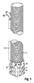
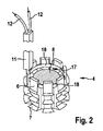
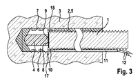
図1には、本発明に係る固定システムが示してある。この固定システムは、図3に示したようなアンカ用基礎3に設けられたアンカ用孔2内にアンカ固定するために設けられたアンカ1と、位置発信器ホルダ4と、位置発信器17とを備えている。アンカ1はねじ山付きロッドである。このねじ山付きロッドは、化学的にアンカ固定するために、つまり、硬化性のもしくは硬化させられた材料5によって固定するために設けられている。この硬化性のもしくは硬化させられた材料5は、例えばセメントモルタルまたは合成樹脂モルタルである。位置発信器ホルダ4は、アンカ1の一方の端部に被嵌されたキャップ18を有している。本実施例では、位置発信器ホルダ4がプラスチックから成っていて、その周面に長手方向スリットを有している。この長手方向スリットによって、位置発信器ホルダ4をアンカ1の端部に保持する半径方向にばね弾性的な複数の保持要素6が形成されている。これらの保持要素6は、アンカ1を半径方向に越えて張り出した鋸歯状の逆鈎7を有している。変形させられていない状態では、保持要素6の逆鈎7が、アンカ用孔2の孔壁をも半径方向に越えて張り出しており、これによって、逆鈎7が位置発信器ホルダ4をアンカ用孔2内に保持している。
FIG. 1 shows a fixing system according to the present invention. This fixing system includes an anchor 1 provided for anchoring in an anchor hole 2 provided in an
位置発信器ホルダ4は、位置発信器17としての金属ディスク、メタライジングされた表面またはその他の導電性の要素を有している。この要素は、アンカ1に対する導電性の対応コンタクト8を形成していて、図2および図3に認めることができる。本実施例では、アンカ1が金属から成っていて、その端面がコンタクト9を形成している。このコンタクト9は、位置発信器ホルダ4が前述のようにアンカ1の端部に支持されていて、これによって、アンカ1の端面が、位置発信器ホルダ4に設けられた対応コンタクト8に接触している場合に、この位置発信器ホルダ4の対応コンタクト8に導電接触している。アンカ1が導電性の材料から成っていない場合には、アンカ1が、コンタクト9を形成するディスクを有していてもよいし、コンタクト9を形成する、アンカ1の端面に設けられたその他の導電性の要素を有していてもよいし、コンタクト9を形成するメタライジングされた端面を有していてもよい。
The
位置発信器17は、金属ディスクとして形成された対応コンタクト8のほかに、別の対応コンタクト10としての金属リングを有している。この金属リングは、位置発信器ホルダ4が前述のようにアンカ1の一方の端部に支持されている場合に、アンカ1を取り囲んでいて、このアンカ1に導電接触している。アンカ1は、別の対応コンタクト10に対しても導電性のコンタクト9を形成している。
The
位置発信器ホルダ4の複数の保持要素6のうちの1つの保持要素6は、位置発信器ホルダ4が前述のようにアンカ1の一方の端部の先端に支持されている場合に、アンカ1の周面に沿って軸線平行に延びる延長部を有している。この延長部はケーブル通路11を形成している。このケーブル通路11内には、アンカ1に沿ってケーブル12が案内されている。このケーブル12は、位置発信器ホルダ4の対応コンタクト8,10に導電的に接続されていて、アンカ1から絶縁されている。
One
アンカ固定するためには、つまり、アンカ用基礎3に設けられたアンカ用孔2内にアンカ1を固定するためには、まず硬化性の材料5がアンカ用孔2内に供給され、次いで、位置発信器ホルダ4を備えたアンカ1が、アンカ用孔2内に挿入される。この位置発信器ホルダ4は、アンカ1の挿入方向で見て前方の端部に位置するようにアンカ1自体の端部に装着されている。このアンカ用孔2は、例えば穿孔されているか、別の形式で作製されているか、すでに存在している。アンカ用基礎3は、例えば岩石、コンクリートまたは組積造から成っている。アンカ1の挿入時には、硬化性の材料5が孔底から孔開口に向かって、一方では位置発信器ホルダ4及びアンカ1と、他方ではアンカ用孔2の孔壁との間の環状ギャップ内に押し退けられ、これによって、硬化性の材料5が、アンカ用孔2内で位置発信器ホルダ4とアンカ1とを取り囲む環状ギャップを埋め尽くす。このとき、材料5が位置発信器17に達してしまうことをキャップ18が阻止している。硬化性の材料5の硬化後(それ以降、この硬化性の材料5は、硬化させられた材料5と呼ばれることになる)、位置発信器ホルダ4とアンカ1とは、アンカ用基礎3に設けられたアンカ用孔2内に材料接続および形状接続によって固定、つまり、アンカ固定されている。ケーブル通路11は、アンカ1とアンカ用孔2との間の環状ギャップ内で孔開口を越えて外向きに延びており、そこで、ケーブル12を接触接続することができる。
For anchoring, i.e. for anchoring the anchor 1 in the anchor hole 2 provided in the
アンカ用孔2内にアンカ固定されたアンカ1が、軸線方向の引張り力の作用に際して、挿入方向と逆方向で引抜き方向もしくはアンカ用孔2から外方へと、孔底から離れる方向で孔開口の方向に変位させられると、まず、アンカ1のコンタクト9が位置発信器17の対応コンタクト8と接触しなくなる。これによって、アンカ1の変位を確認することができる。アンカ1が引き続き孔開口の方向に変位させられると、アンカ1のコンタクト9が位置発信器17の別の対応コンタクト10とも接触しなくなる。本実施例では、アンカ1が0.8mm以上変位させられると、アンカ1のコンタクト9が別の対応コンタクト10と接触しなくなる。本実施例では、アンカ1を形成するねじ山付きロッドが、M12サイズのねじ山を有している。本実施例では、アンカ用孔2の孔開口の方向へのアンカ1の最大0.8mmの変位が、許容可能な誤差の範囲内と見なされ、より大きな変位は許容不可であり、安全対策、例えば1つまたはそれ以上の代替アンカの設置を必要とする。アンカ用孔2の孔開口の方向へのアンカ1の変位の許容可能な誤差が維持されているかまたは上回っているかは、アンカ1のコンタクト9と位置発信器ホルダ4の別の対応コンタクト10との導電接触の有無に基づき、アンカ用基礎3の外側のケーブル12にて確認することができる。
When the anchor 1 fixed in the anchor hole 2 is acted on by the pulling force in the axial direction, the anchor 1 is pulled out in the direction opposite to the insertion direction or is opened from the anchor hole 2 in the direction away from the hole bottom. When it is displaced in the direction of, the contact 9 of the anchor 1 does not come into contact with the
電気的なコンタクト9としてのアンカ1と、両対応コンタクト8,10とは、アンカ用孔2の長手方向に連続して配置された2つの電気的な位置発信器を形成している。位置発信器ホルダ4と、この位置発信器ホルダ4に配置された対応コンタクト8,10とは、硬化させられた材料5によってアンカ用孔2内に不動にアンカ固定されていて、アンカ1が孔開口の方向に変位させられる場合に一緒に移動することはない。これによって、アンカ用基礎3に対するアンカ1の変位を確認することができる。
The anchor 1 as the electrical contact 9 and the
アンカ用孔1の外側にあって、位置発信器ホルダ4の変形させられていない状態では、保持要素6の逆鈎7が、アンカ用孔2の直径よりも大きな直径もしくはこのようなアンカ用孔2の、アンカ1に対応する公称直径よりも大きな直径に設定されており、これによって、位置発信器ホルダ4がアンカ用孔2内に位置している場合には、保持要素6の逆鈎7が予荷重を伴ってアンカ用孔2の孔壁を押圧している。したがって、位置発信器ホルダ4は、孔直径が位置発信器ホルダ4の保持要素6の逆鈎7の直径よりも大きくない場合に、硬化性の材料5なしでもアンカ用孔2内にとどまっている。よって、位置発信器ホルダ4は、アンカ、例えば拡開アンカとも使用することができる。この拡開アンカは、硬化性の材料なしで、例えば拡開により機械的にアンカ用孔内にアンカ固定される(図示せず)。好ましくは、このようなアンカと、位置発信器ホルダ4とは、この位置発信器ホルダ4が、先だってアンカ用孔内に挿入される方のアンカの端部に支持可能であるかまたは別の形式で解離可能に取付け可能であるように構成されている。位置発信器ホルダ4とアンカとの解離可能な結合は、アンカ用孔2内での、孔壁を押圧する逆鈎7による位置発信器ホルダ4の保持力よりも弱く、これによって、位置発信器ホルダ4は、アンカが孔開口の方向に変位させられる場合に、アンカと一緒に移動することはない。
When the
図4では、アンカ1が同じくねじ山付きロッドであり、位置発信器ホルダ4が、別の対応コンタクト10としての金属リングを有していないことを除いて、図1〜図3に関して説明したものと同様に形成されている。図4に示したアンカ1はその端面に、コンデンサ14の一方の部材13としての金属ディスクを有している。位置発信器ホルダ4は、本発明のこの構成においてコンデンサ14の他方の部材15を成す、半径方向平面に配置された金属ディスクを有している。コンデンサ14の第1の部材13を成す一方の金属ディスクは、アンカ1が金属またはその他の導電性の材料から成っている場合には、アンカ1から電気的に絶縁されている。コンデンサ14の、位置発信器ホルダ4に配置された第2の他方の部材15は、位置基準として役立つ位置発信器17を形成している。位置発信器ホルダ4は、アンカ1に対するストッパ16としての、内向きに設けられた全周にわたって延びるつばを有している。このつばは、コンデンサ14の両部材13,15の間に所定の間隔を確保している。アンカ1がアンカ用孔2内で孔開口の方向に変位させられると、コンデンサ14の両部材13,15の間の間隔が増加させられ、コンデンサ14の容量が減少させられるかまたはいずれにせよ変化させられる。コンデンサ14の他方の部材15を備えた位置発信器ホルダ4は、アンカ用孔内で不動であり、孔開口の方向へのアンカ1の変位時に一緒に移動することはない。コンデンサ14の容量の測定によって、アンカ1の変位量が測定可能となる。例えば、コンデンサ14の充電時間または放電時間が測定される。
In FIG. 4, what has been described with reference to FIGS. 1 to 3, except that the anchor 1 is also a threaded rod and the
繰返しを避けるために、図4の説明に補足して、図1〜図3の説明が参照される。図4では、同一の要素に図1〜図3と同じ符号が付してある。コンデンサ14の両部材13,15は、一方の端部に位置発信器ホルダ4が支持されたアンカ1の電気的な位置発信器を構成している。
To avoid repetition, reference is made to the description of FIGS. 1-3, supplementing the description of FIG. In FIG. 4, the same elements are designated by the same reference numerals as those in FIGS. 1 to 3. Both members 13 and 15 of the condenser 14 constitute an electric position transmitter of the anchor 1 in which the
1 アンカ
2 アンカ用孔
3 アンカ用基礎
4 位置発信器ホルダ
5 硬化性のもしくは硬化させられた材料
6 保持要素
7 逆鈎
8 対応コンタクト
9 コンタクト
10 別の対応コンタクト
11 ケーブル通路
12 ケーブル
13 コンデンサ14の部分
14 コンデンサ
15 コンデンサ14の他方の部分
16 ストッパ
17 位置発信器
18 キャップ
1 Anchor 2 Hole for
Claims (12)
前記アンカ用孔(2)内に電気的な位置発信器(17)が配置されており、前記アンカ(1)が前記アンカ用孔(2)から外方に移動させられる場合に、前記アンカ(1)が前記位置発信器(17)に対して移動させられることを特徴とする、配置構造。 In the arrangement structure of the anchor (1) in the anchor hole (2) provided in the anchor base (3),
An electric position transmitter (17) is arranged in the anchor hole (2), and when the anchor (1) is moved outward from the anchor hole (2), the anchor ( Arrangement, characterized in that 1) is moved relative to the position transmitter (17).
Applications Claiming Priority (3)
| Application Number | Priority Date | Filing Date | Title |
|---|---|---|---|
| DE102017106485.0 | 2017-03-27 | ||
| DE102017106485.0A DE102017106485A1 (en) | 2017-03-27 | 2017-03-27 | Arrangement of an anchor in an anchor hole and fastening system |
| PCT/EP2018/055002 WO2018177675A1 (en) | 2017-03-27 | 2018-03-01 | Arrangement of an anchor in an anchoring hole, and fastening system |
Publications (2)
| Publication Number | Publication Date |
|---|---|
| JP2020515744A true JP2020515744A (en) | 2020-05-28 |
| JP7038731B2 JP7038731B2 (en) | 2022-03-18 |
Family
ID=61557275
Family Applications (1)
| Application Number | Title | Priority Date | Filing Date |
|---|---|---|---|
| JP2019552989A Expired - Fee Related JP7038731B2 (en) | 2017-03-27 | 2018-03-01 | Anchor placement structure and fixing system in the anchor hole |
Country Status (6)
| Country | Link |
|---|---|
| US (1) | US11293470B2 (en) |
| EP (1) | EP3601815B1 (en) |
| JP (1) | JP7038731B2 (en) |
| CN (1) | CN110462228B (en) |
| DE (1) | DE102017106485A1 (en) |
| WO (1) | WO2018177675A1 (en) |
Cited By (1)
| Publication number | Priority date | Publication date | Assignee | Title |
|---|---|---|---|---|
| KR102414976B1 (en) * | 2021-06-24 | 2022-07-04 | 주식회사 라온건설기술 | Acupressure type permanent anchor with built-in anchor force measuring sensor and its construction method |
Families Citing this family (5)
| Publication number | Priority date | Publication date | Assignee | Title |
|---|---|---|---|---|
| DE102017106485A1 (en) * | 2017-03-27 | 2018-09-27 | Fischerwerke Gmbh & Co. Kg | Arrangement of an anchor in an anchor hole and fastening system |
| JP7339789B2 (en) * | 2019-07-02 | 2023-09-06 | 東日本旅客鉄道株式会社 | Anchor and anchor construction method |
| CN110984396A (en) * | 2019-12-24 | 2020-04-10 | 福州鼓楼纹英建筑工程有限责任公司 | Rear-mounted anchor net and operation method thereof |
| CN111287023B (en) * | 2020-02-19 | 2021-09-10 | 中铁第四勘察设计院集团有限公司 | Anchor bolt and ballastless track |
| EP4295015B1 (en) | 2021-02-19 | 2024-10-23 | Rocbolt Technolgies (Pty) Ltd. | A rock bolt assembly having an indicator |
Citations (9)
| Publication number | Priority date | Publication date | Assignee | Title |
|---|---|---|---|---|
| JPH07197457A (en) * | 1992-12-23 | 1995-08-01 | Suspa Spannbeton Gmbh | Monitoring device for structural elements, especially tensile units for soil or rock anchors, pressure units for piles, prestressed concrete structures and tightening units for cable-stayed bridge ropes |
| US6185886B1 (en) * | 1998-04-27 | 2001-02-13 | Fischerwerke Artur Fischer Gmbh & Co. Kg | Fixing element for reinforcement connection with a secondary action, especially for earthquake-resistant securement |
| JP2002070005A (en) * | 2000-08-28 | 2002-03-08 | Toa Grout Kogyo Co Ltd | anchor |
| JP2007155475A (en) * | 2005-12-05 | 2007-06-21 | Shikoku Electric Power Co Inc | Tension detecting method for tendon |
| JP2009293325A (en) * | 2008-06-06 | 2009-12-17 | Japan Conservation Engineers Co Ltd | Apparatus for confirming condition of anchoring function |
| JP2014500477A (en) * | 2010-10-11 | 2014-01-09 | ヒルティ アクチエンゲゼルシャフト | Sensor devices such as anchor bolts |
| JP2014141779A (en) * | 2013-01-22 | 2014-08-07 | Nippon Steel & Sumikin Metal Products Co Ltd | Slope variation detection structure in method for stabilizing slope |
| JP2017155479A (en) * | 2016-03-01 | 2017-09-07 | 株式会社アミック | Anchor and diagnosis method |
| JP2019500522A (en) * | 2015-12-24 | 2019-01-10 | ソイルテック コリア カンパニー リミテッドSoiltech.Korea Co.,Ltd | Ground anchor capable of self-diagnosis of stress and its construction method |
Family Cites Families (34)
| Publication number | Priority date | Publication date | Assignee | Title |
|---|---|---|---|---|
| US3885423A (en) * | 1971-12-07 | 1975-05-27 | Bergwerksverband Gmbh | Method of measuring changes in the area surrounding a mining cavity |
| DE2659138A1 (en) * | 1976-12-28 | 1978-06-29 | Fischer Artur Dr H C | DOWEL TO CONCRETE IN A DRILL HOLE |
| DE3344010C1 (en) * | 1983-12-06 | 1985-06-20 | Festo KG, 7300 Esslingen | Bracket for proximity sensors |
| US4642964A (en) * | 1984-09-27 | 1987-02-17 | Kellison Roger C | Grout in place fastener system |
| DE3716703A1 (en) * | 1987-05-19 | 1988-12-01 | Hilti Ag | CONNECTING ANCHOR WITH ELECTRICAL INSULATION |
| US5490365A (en) * | 1994-05-11 | 1996-02-13 | Roth; Steven A. | Anchor bolt assembly |
| DE4427244A1 (en) * | 1994-08-03 | 1996-02-08 | Prozesautomation Kohler Gmbh | Measuring physical and chemical parameters e.g. temp., resistance-conductivity or humidity, in building materials |
| DE4439861A1 (en) * | 1994-11-08 | 1996-05-09 | Fischer Artur Werke Gmbh | Anchor bolt for anchoring using a compound |
| US5806275A (en) * | 1996-10-07 | 1998-09-15 | Giannuzzi; Anthony C. | Chemical anchor bolt and cap assembly |
| JPH09126481A (en) * | 1995-10-31 | 1997-05-16 | Mitsubishi Cable Ind Ltd | Thermal storage floor heating system |
| DE10030099C2 (en) | 2000-06-19 | 2002-06-20 | Bundesrep Deutschland | Strain and tension sensor in solid materials |
| US6393795B1 (en) * | 2000-08-16 | 2002-05-28 | Illinois Tool Works Inc. | Adhesive anchor and system |
| DE102004052570A1 (en) * | 2004-10-29 | 2006-05-04 | Fischerwerke Artur Fischer Gmbh & Co. Kg | The anchor assembly |
| KR100858116B1 (en) * | 2008-03-24 | 2008-09-10 | (주)성문엔지니어링 | Underground switchboard box |
| DE102008031590A1 (en) * | 2008-07-03 | 2010-01-07 | Fischerwerke Gmbh & Co. Kg | Test method and test system for expansion anchors |
| DE102008040687A1 (en) * | 2008-07-24 | 2010-01-28 | Hilti Aktiengesellschaft | anchoring element |
| CA2686447C (en) * | 2008-11-20 | 2018-06-12 | Matthews Resources, Inc. | Method and system of affixing a plaque to a solid surface |
| KR101173768B1 (en) * | 2010-08-26 | 2012-08-13 | 한전케이피에스 주식회사 | A bolt structure for temperature sensor fixing |
| DE102012201293A1 (en) * | 2012-01-31 | 2013-08-01 | Hilti Aktiengesellschaft | Anchor system, in particular undercut anchor system |
| CN203310698U (en) * | 2013-05-10 | 2013-11-27 | 天地科技股份有限公司 | Coal mine tunnel coal-rock mass anchoring performance testing device |
| US9188520B1 (en) * | 2013-11-21 | 2015-11-17 | Engineered Mine Solutions, Llc | Tensile testing apparatus |
| DE102014100921A1 (en) | 2014-01-27 | 2015-07-30 | Ingenieurbüro Tim Wissner und Kai Wissner GbR (vertretungsberechtigter Gesellschafter Kai Wissner, 69493 Hirschberg) | Screw dowel and method for producing a screw plug |
| CN103850254B (en) * | 2014-04-01 | 2015-07-08 | 兰州理工大学 | Slope anchoring structure and construction method with early warning energy consumption shock absorption control system |
| JP6308902B2 (en) * | 2014-07-22 | 2018-04-11 | 原子燃料工業株式会社 | Non-destructive inspection method and non-destructive inspection device for anchor bolt |
| CN204064227U (en) * | 2014-08-12 | 2014-12-31 | 大连海事大学 | A rock mass displacement monitoring device |
| CN204755515U (en) * | 2015-05-13 | 2015-11-11 | 刘平原 | Intelligence crab -bolt |
| CN204807075U (en) * | 2015-07-17 | 2015-11-25 | 北京矿冶研究总院 | Rock mass internal catastrophe process continuous monitoring equipment |
| DE202015104390U1 (en) * | 2015-08-19 | 2016-11-22 | Sick Ag | sensor |
| CN205578437U (en) * | 2016-04-27 | 2016-09-14 | 中国兵器装备集团摩托车检测技术研究所 | A inflation formula crossover sub for inciting somebody to action rod sensor installs on pressure vessel |
| CN105865397B (en) * | 2016-05-10 | 2019-01-01 | 中国电建集团华东勘测设计研究院有限公司 | The effective anchorage depth lossless detection method of overall length binding type anchor pole and device |
| KR101655424B1 (en) * | 2016-05-17 | 2016-09-08 | 주식회사 한국건설방재연구원 | Measure apparatus for vibration displacement of bridge uper structure |
| CN105863701B (en) * | 2016-05-30 | 2018-01-30 | 辽宁工程技术大学 | A kind of anchor sensor |
| DE102017106485A1 (en) * | 2017-03-27 | 2018-09-27 | Fischerwerke Gmbh & Co. Kg | Arrangement of an anchor in an anchor hole and fastening system |
| US11268247B2 (en) * | 2017-12-26 | 2022-03-08 | MOW Equipment Solutions, Inc. | Adaptive railway fastener and anchor installation system |
-
2017
- 2017-03-27 DE DE102017106485.0A patent/DE102017106485A1/en not_active Withdrawn
-
2018
- 2018-03-01 US US16/494,365 patent/US11293470B2/en not_active Expired - Fee Related
- 2018-03-01 JP JP2019552989A patent/JP7038731B2/en not_active Expired - Fee Related
- 2018-03-01 WO PCT/EP2018/055002 patent/WO2018177675A1/en not_active Ceased
- 2018-03-01 CN CN201880022304.4A patent/CN110462228B/en active Active
- 2018-03-01 EP EP18708399.3A patent/EP3601815B1/en active Active
Patent Citations (9)
| Publication number | Priority date | Publication date | Assignee | Title |
|---|---|---|---|---|
| JPH07197457A (en) * | 1992-12-23 | 1995-08-01 | Suspa Spannbeton Gmbh | Monitoring device for structural elements, especially tensile units for soil or rock anchors, pressure units for piles, prestressed concrete structures and tightening units for cable-stayed bridge ropes |
| US6185886B1 (en) * | 1998-04-27 | 2001-02-13 | Fischerwerke Artur Fischer Gmbh & Co. Kg | Fixing element for reinforcement connection with a secondary action, especially for earthquake-resistant securement |
| JP2002070005A (en) * | 2000-08-28 | 2002-03-08 | Toa Grout Kogyo Co Ltd | anchor |
| JP2007155475A (en) * | 2005-12-05 | 2007-06-21 | Shikoku Electric Power Co Inc | Tension detecting method for tendon |
| JP2009293325A (en) * | 2008-06-06 | 2009-12-17 | Japan Conservation Engineers Co Ltd | Apparatus for confirming condition of anchoring function |
| JP2014500477A (en) * | 2010-10-11 | 2014-01-09 | ヒルティ アクチエンゲゼルシャフト | Sensor devices such as anchor bolts |
| JP2014141779A (en) * | 2013-01-22 | 2014-08-07 | Nippon Steel & Sumikin Metal Products Co Ltd | Slope variation detection structure in method for stabilizing slope |
| JP2019500522A (en) * | 2015-12-24 | 2019-01-10 | ソイルテック コリア カンパニー リミテッドSoiltech.Korea Co.,Ltd | Ground anchor capable of self-diagnosis of stress and its construction method |
| JP2017155479A (en) * | 2016-03-01 | 2017-09-07 | 株式会社アミック | Anchor and diagnosis method |
Cited By (1)
| Publication number | Priority date | Publication date | Assignee | Title |
|---|---|---|---|---|
| KR102414976B1 (en) * | 2021-06-24 | 2022-07-04 | 주식회사 라온건설기술 | Acupressure type permanent anchor with built-in anchor force measuring sensor and its construction method |
Also Published As
| Publication number | Publication date |
|---|---|
| EP3601815B1 (en) | 2022-08-31 |
| US11293470B2 (en) | 2022-04-05 |
| JP7038731B2 (en) | 2022-03-18 |
| WO2018177675A1 (en) | 2018-10-04 |
| US20200049184A1 (en) | 2020-02-13 |
| CN110462228A (en) | 2019-11-15 |
| CN110462228B (en) | 2021-08-31 |
| EP3601815A1 (en) | 2020-02-05 |
| DE102017106485A1 (en) | 2018-09-27 |
Similar Documents
| Publication | Publication Date | Title |
|---|---|---|
| JP7038731B2 (en) | Anchor placement structure and fixing system in the anchor hole | |
| CN105992878B (en) | Intumescent anchor with anisotropic coefficient of friction | |
| CN105705804B (en) | Expansion anchor with groove in expansion cone | |
| TWI551782B (en) | Expanding anchor | |
| CN104081067B (en) | Anchor system | |
| DK3060816T3 (en) | Expansion anchor with expansion sleeve with high strength sections | |
| US6634147B2 (en) | Process for the installation and tensioning of a brace having a false bearing, in particular a stay cable for a cable-stayed bridge and anchoring device with which to carry out the process | |
| US20170136551A1 (en) | Clamping bushing and clamping device | |
| CN105765240B (en) | Expansion anchor with expansion element for fixing the sleeve | |
| TWI693375B (en) | Fixed structure and its measuring method | |
| US20180094926A1 (en) | Penetrometer | |
| AU2008351618B2 (en) | Improved sliding anchor | |
| CN105066926A (en) | Anchoring device of drill hole multi-point displacement meter | |
| AU2023220733B2 (en) | Fastening element comprising sensor arranged in a tapering section and protected by means of a protective device | |
| WO2017087995A2 (en) | Loss of load indicator device | |
| HUP0400755A2 (en) | Anchor sleeve for injection fixing | |
| CN108331818B (en) | Expansion anchor for thin plates | |
| US20120282058A1 (en) | Anchor Rod | |
| CN104061220B (en) | A kind of setscrew utilizing hammering mode to install | |
| CN110914583A (en) | Securing ring and assembly of hose and securing ring | |
| KR200344958Y1 (en) | Tension member removable anchoring apparatus with wedge spring and wedge-cone spring | |
| KR101852142B1 (en) | Construction method for pile using load cell | |
| CN110242349A (en) | Pressure sensing embedded chute | |
| EP4590935A1 (en) | A displacement measuring device for installation in a rock hole | |
| JP2016138422A (en) | Post-installed anchor and construction method thereof |
Legal Events
| Date | Code | Title | Description |
|---|---|---|---|
| A621 | Written request for application examination |
Free format text: JAPANESE INTERMEDIATE CODE: A621 Effective date: 20201204 |
|
| A977 | Report on retrieval |
Free format text: JAPANESE INTERMEDIATE CODE: A971007 Effective date: 20211008 |
|
| A131 | Notification of reasons for refusal |
Free format text: JAPANESE INTERMEDIATE CODE: A131 Effective date: 20211108 |
|
| A521 | Request for written amendment filed |
Free format text: JAPANESE INTERMEDIATE CODE: A523 Effective date: 20220114 |
|
| TRDD | Decision of grant or rejection written | ||
| A01 | Written decision to grant a patent or to grant a registration (utility model) |
Free format text: JAPANESE INTERMEDIATE CODE: A01 Effective date: 20220207 |
|
| A61 | First payment of annual fees (during grant procedure) |
Free format text: JAPANESE INTERMEDIATE CODE: A61 Effective date: 20220308 |
|
| R150 | Certificate of patent or registration of utility model |
Ref document number: 7038731 Country of ref document: JP Free format text: JAPANESE INTERMEDIATE CODE: R150 |
|
| LAPS | Cancellation because of no payment of annual fees |